EP3992141A1 - Device for lifting vehicles - Google Patents
Device for lifting vehicles Download PDFInfo
- Publication number
- EP3992141A1 EP3992141A1 EP21202520.9A EP21202520A EP3992141A1 EP 3992141 A1 EP3992141 A1 EP 3992141A1 EP 21202520 A EP21202520 A EP 21202520A EP 3992141 A1 EP3992141 A1 EP 3992141A1
- Authority
- EP
- European Patent Office
- Prior art keywords
- locking
- designed
- locking element
- arms
- locking elements
- Prior art date
- Legal status (The legal status is an assumption and is not a legal conclusion. Google has not performed a legal analysis and makes no representation as to the accuracy of the status listed.)
- Granted
Links
- 230000000295 complement effect Effects 0.000 claims description 3
- 230000033001 locomotion Effects 0.000 description 19
- 230000003993 interaction Effects 0.000 description 5
- 238000009434 installation Methods 0.000 description 4
- 238000013519 translation Methods 0.000 description 4
- 238000013459 approach Methods 0.000 description 3
- 239000000463 material Substances 0.000 description 3
- 238000000034 method Methods 0.000 description 3
- 230000004913 activation Effects 0.000 description 2
- 230000000694 effects Effects 0.000 description 2
- 238000012423 maintenance Methods 0.000 description 2
- 230000009471 action Effects 0.000 description 1
- 230000003213 activating effect Effects 0.000 description 1
- 230000006978 adaptation Effects 0.000 description 1
- 230000002457 bidirectional effect Effects 0.000 description 1
- 230000008859 change Effects 0.000 description 1
- 230000008878 coupling Effects 0.000 description 1
- 238000010168 coupling process Methods 0.000 description 1
- 238000005859 coupling reaction Methods 0.000 description 1
- 230000001419 dependent effect Effects 0.000 description 1
- 238000003780 insertion Methods 0.000 description 1
- 230000037431 insertion Effects 0.000 description 1
- 230000001788 irregular Effects 0.000 description 1
- 238000004519 manufacturing process Methods 0.000 description 1
- 239000002184 metal Substances 0.000 description 1
- 239000007769 metal material Substances 0.000 description 1
- 238000012986 modification Methods 0.000 description 1
- 230000004048 modification Effects 0.000 description 1
- 230000000750 progressive effect Effects 0.000 description 1
- 230000001737 promoting effect Effects 0.000 description 1
- 230000008439 repair process Effects 0.000 description 1
- 230000002441 reversible effect Effects 0.000 description 1
- 230000001360 synchronised effect Effects 0.000 description 1
Images


Classifications
-
- B—PERFORMING OPERATIONS; TRANSPORTING
- B66—HOISTING; LIFTING; HAULING
- B66F—HOISTING, LIFTING, HAULING OR PUSHING, NOT OTHERWISE PROVIDED FOR, e.g. DEVICES WHICH APPLY A LIFTING OR PUSHING FORCE DIRECTLY TO THE SURFACE OF A LOAD
- B66F7/00—Lifting frames, e.g. for lifting vehicles; Platform lifts
- B66F7/28—Constructional details, e.g. end stops, pivoting supporting members, sliding runners adjustable to load dimensions
-
- B—PERFORMING OPERATIONS; TRANSPORTING
- B66—HOISTING; LIFTING; HAULING
- B66F—HOISTING, LIFTING, HAULING OR PUSHING, NOT OTHERWISE PROVIDED FOR, e.g. DEVICES WHICH APPLY A LIFTING OR PUSHING FORCE DIRECTLY TO THE SURFACE OF A LOAD
- B66F7/00—Lifting frames, e.g. for lifting vehicles; Platform lifts
- B66F7/06—Lifting frames, e.g. for lifting vehicles; Platform lifts with platforms supported by levers for vertical movement
- B66F7/065—Scissor linkages, i.e. X-configuration
Definitions
- the present invention can be situated in the technical sector of bodywork and mechanical workshop equipment and relates to a lifting device for vehicles.
- the lifting device according to the present invention can be of the scissor type, and/or with two columns and/or or a type with an air spring.
- These devices commonly called lifting bridges or simply car lifts, consist of a load-bearing structure that can be anchored to the ground (or over a pit for total or partial embedding of said lift in the floor) and a movable structure, which is fixed to the load-bearing structure, and designed to undergo a translational movement in a vertical direction between two end positions.
- the movable structure is designed to be raised/lowered between a lower position, in which it is substantially close to the ground (or flush with the floor in the embedded versions), and an upper position in which it reaches a pre-determined height from the ground (generally less than 2.5 meters).
- a plurality of arms is also provided which are anchored to the movable structure and provided with respective terminal elements, commonly called pads, whose upper surface is intended to come into contact with the bottom of the vehicle to be lifted.
- the pads constitute the only part of the movable structure that interacts with the vehicle when it is lifted upwards or during its downward descent.
- the weight of the vehicle therefore, is borne entirely by the movable structure and the load-bearing structure of the device through the pads and the arms.
- the pads (and thus the corresponding arms supporting that support the pads) are equal in number and equally distributed between the right side and the left side of the vehicle to promote a uniform weight distribution of the vehicle over the structure.
- the arms that support the pads are hinged to the movable structure to allow their selective rotation by an operator who is preparing to lift the vehicle.
- the arms When the lifting device is not in operation, the arms can be placed in a rest position in which they are in contact with (or in proximity to) the movable structure to reduce the overall dimensions of the device.
- the operator Before lifting the vehicle, the operator, manually or through an automatic actuation system, will rotate the individual arms up to a final position in which the pad comes into contact with the bottom of the vehicle (usually at the points predefined by the vehicle manufacturer).
- This rotation can be caused by a chance interaction of the arms with people and/or with moving objects present in the installation environment of the lifting device.
- a chance movement of the arms can be the result of contact between the same and the body of one or more operators who are preparing to work on the bottom of the vehicle, or be caused by an interaction with moving elements such as trolleys, cables, compressed air conducts, etc.
- a movement of the arms occurring just prior to the interaction between the pad and the vehicle can be dangerous for the latter and for the operators located in the vicinity of the device.
- the pad could come into contact with fragile parts of the bottom or with components of the vehicle not suitable for supporting its weight (portions of the body, components of various types, tube, etc.). Furthermore, the degree of freedom that the arms have during lifting could give rise to an unstable contact between the bottom of the vehicle and the pad.
- the present invention intends to overcome the aforementioned technical drawbacks by providing a lifting device for vehicles which is particularly safe and reliable.
- the main object of the present invention is to provide a lifting device for vehicles capable of keeping the position of the vehicle stable during its raising and lowering.
- a further object of the present invention is to provide a lifting device for vehicles that is simple to manufacture and particularly flexible in terms of its use.
- Another object of the present invention is to provide a lifting device for vehicles which exhibits high durability over time and requires reduced maintenance.
- the object of the present invention is to provide lifting device for vehicles the configuration of which satisfies all the safety regulations stipulated in various countries with reference to the sector of bodywork or vehicle assistance.
- the present invention relates to a lifting device for vehicles which will be indicated in the following description by the reference number 1 .
- the device 1 can be used to lift road vehicles with different sizes and functions such as, for example, cars, vans, trucks, buses etc.
- Figures 1 to 10 show a preferred embodiment of the lifting device 1 according to the present invention which comprises suitable adaptations and dimensional modifications depending on the size of the vehicle to be raised/lowered (car, truck, bus, caravan, etc.).
- the lifting device 1 comprises a stationary structure 2 intended to be placed on the ground S .
- the stationary structure 2 can consist of a support base 3 which has a substantially rectangular shape and is designed to be stably anchored to the ground S by means of a plurality of locking screws (not shown in the figures).
- the support base 3 can be embedded inside a special recess made in the floor of the installation environment.
- a movable structure 4 operatively connected to the stationary structure 2 and operation means 5 designed to promote the selective and controlled lifting or lowering of the movable structure 4 with respect to the stationary structure 2 between two predetermined limit positions.
- the movable structure 4 can comprise a platform 6 made of a metallic material and having an upper surface 7 which is substantially flat and horizontal.
- the platform 6 is connected to the support base 3 by means of two pairs of parallel side members 8 , 9 having a lower end 10, 10 ' fixed or hinged to the base 3 and an upper end 11 hinged to the platform 6 .
- the lower end of a pair of side members 8 will be hinged to the base 3 in a fixed position while the lower end 10 of the other pair of side members 9 is anchored to the base 3 to be able to translate along a substantially horizontal direction X .
- each side member is arranged on opposite sides with respect to a vertical centerline plane passing through the platform 6 and indicated in the figures by the symbol ⁇ .
- the pairs of side members 8 , 9 are joined together via a horizontal crosspiece 12 arranged in a position substantially equidistant from the ends 10, 10' and in correspondence with the centerline plane ⁇ , as is better visible in Figures 2 and 3 .
- the operation means 5 comprises a piston 13 provided with a movable rod 14 whose head 15 is hinged to a bracket 16 which is in turn connected to the crosspiece 12 in a rotatable manner.
- the progressive extension (or return) of the rod 14 of the piston 13 allows the counterclockwise (or clockwise) semi-rotation of the bracket 16 by promoting the translational movement of the crosspiece 12 upwards (or downwards) along the centerline plane ⁇ .
- the cylinder 17 of the piston 13 is constrained to the base 3 and during its operation the lower end 10 ' of the side members 9 can translate towards the inside of the base 3 (in the case of a forward movement of the rod 14 ) or towards the outside of the base 3 (in the case of a return movement of the rod 14 ).
- pairs of side members 8, 9 are free to move between a position in which they are substantially horizontal and parallel to each other (complete lowering of the movable structure, maximum retraction of the rod 14 ) to a position in which they are arranged according to a symmetrical "X" shape with respect to the centerline plane (complete raising of the movable structure, maximum extension of the rod 14 ).
- the piston 13 can be of the oleodynamic or pneumatic type and can be replaced by any linear actuator of a different nature (i.e., electrical) adapted to promote the translational and bidirectional movement of a thrust element which can be anchored to the crosspiece 12 .
- the platform 6 translates vertically between a lower limit position, in which it is substantially placed in proximity to the support base 3 , and an upper limit position in which it is placed at a predetermined height from the ground S .
- the platform in the upper limit position can reach a height h that does not exceed two meters.
- the lifting device 1 further comprises a plurality of arms 18 provided with one end 19 hinged to the movable structure 4 and a free opposite end 20 to which is associated a pad 21 designed to come into contact with the bottom of the vehicle to be lifted.
- the device 1 typically comprises an even number of arms 18 uniformly arranged along the side edges 22 , 23 of the platform 6 .
- the use four arms 18 distributed in pairs along the respective edges 22, 23 of the platform 6 is envisaged.
- Each arm 18 is consequently free to selectively rotate around a respective substantially vertical hinge axis Y between an inactive position and an active position.
- the arms 18 can be substantially straight and, in the inactive position (not visible in the figures), they can be collected in proximity of the side edges 22 , 23 of the platform 6 to reduce the overall dimensions of the device 1 .
- the angle ⁇ can be the same for all arms 18 or can be different for one or more of them.
- the active position can be the same for all the arms 18 or can vary for one or more arms, according to the requirements.
- the rotation of the arms 18 between the two inactive/active positions can be performed manually by an operator or can be carried out in an automatic or semiautomatic manner through the use of suitable actuators.
- the configuration of the invention illustrated in the figures refers to this second case, in which four small pistons 24 having the bottom of the cylinder hinged to the platform and the head 25 of the rod hinged to the respective arm 18 are provided.
- the pads 21 can be fixed to the arms 18 in a removable manner and their vertical position with respect to the latter can be manually adjusted by the operator.
- the upper surface 26 of the pads 21 is intended to come into contact with the bottom of the vehicle and for this reason is located at a height from the ground h' slightly higher than the height h of the platform 6 , generally higher by a few centimetres.
- the vehicle interacts exclusively with the pads 21 while the platform 6 is designed to never come into contact with the bottom or with other parts of the means of transport, which is raised with respect to the ground S .
- the pads 21 are generally made of a semi-rigid material suitable for supporting the weight of the vehicle, generally rubber or other similar polymeric materials.
- the pad 21 can be anchored directly to the arm 18 or can be associated with the latter in a removable manner, as better illustrated in Figures 2 , 4 , 5 and 8 .
- the pad 21 is integral with a section of profiled tube 27 (generally having a rectangular cross-section) having an internal cavity 28 inside which the end portion of the arm 18 can be inserted in a sliding manner.
- the section of tube 27 can be fixed to the arm 18 by means of rapid connection means (for example the insertion of a pin into suitable holes formed on the arm and on the tube) or with other fastening elements known per se and not described in the following description.
- locking means 29 designed to selectively and automatically lock the plurality of arms 18 when the latter are in the active position are provided.
- the presence of the locking means 29 prevents the arms from rotating inadvertently and/or suddenly from their active position during their interaction with the vehicle floor, or during the raising/lowering of the vehicle itself.
- locking means used in the present description is intended to refer to means of reversible type, which can be selectively operated to effect both the rotational locking of one or more arms in an active position, as well as the unlocking of the same in order to allow them to rotate from the active position to the inactive position.
- the locking means 29 can be configured to selectively lock one or more arms 18 in the active position, for example two out of four arms.
- the locking means 29 can be configured to selectively lock all arms 18 in the active position.
- the locking means 29 can promote the locking of all arms 18 in the active position substantially in simultaneous, i.e., at the same moment in time.
- the locking means 29 can be configured to promote the locking of the arms 18 at different moments in time, for example one after the other or in accordance with a precise locking sequence.
- the locking means 29 can comprise a plurality of first locking elements 30 rigidly connected to the hinged end 19 of a respective arm 18 .
- the first locking elements 30 can thus be designed to rotate around the hinge axis Y of the corresponding arm 18 when a movement between the active position and the inactive position (or vice versa) is conveyed to the arm 18 .
- the first locking elements 30 are positioned on the outer surface 31 of the platform, above the respective arm 18 .
- first locking elements 30 can be manufactured with a plate of reduced thickness and are integral with the hinge pin 32 passing through the end 19 of the respective arm 18 .
- the locking means 30 comprise a plurality of second locking elements 33 placed in proximity to the first locking elements 30 .
- Said second locking means 33 are better visible in particular in Figures 4 - 6 .
- Each first locking element 30 can be associated with a corresponding second locking element 33 and the latter can be integral with the movable structure 4 .
- the second locking elements are anchored to the upper surface 31 of the platform 6.
- the second locking element 33 can be obtained from a section of metal profile with a reduced thickness (flat profile).
- each second locking element 33 can have an elongated shape that extends along a respective direction of extension W substantially horizontal and orthogonal to the hinge axis Y of the respective arm 18 .
- the second locking element 33 can be located in proximity of the side edges 22, 23 of the platform 6 and its extension direction W can be substantially parallel to said edge.
- each pair of second locking elements 33 is arranged to define a single direction W along which both elements 33 extend.
- first locking elements 30 and the second locking elements 33 have respective end edges 34 , 35 arranged in a mutually facing position.
- Said edges 34 , 35 are provided with respective shaped portions 36 , 37 having at least one section with a complementary shape to each other.
- the complementary shape of the shaped portions 36, 37 therefore allows the edges 34, 35 to mutually commit to each other when they come into contact.
- the first locking element 30 has a substantially semicircular edge facing the second locking element 33 .
- a toothing 38 (clearly visible in Figure 6 ), the extension of which is chosen so that the teeth are always facing the second locking element 33 , is formed at a portion 36 of said edge.
- the toothing 38 performed on the edge portion 36 of the first locking element 30 always faces the second locking element 33 , regardless of the rotation angle ⁇ chosen to determine the active position of the corresponding arm 18 .
- the second locking element 33 has an edge portion 37 which is also semicircular and faces the toothed edge portion 36 of the first locking element 30 .
- the semicircular edge portion 37 of the second locking element 33 has a radius substantially equal to that of the toothed semicircular edge portion 36 of the first locking element 30 .
- the edge portion 37 of the second locking element 33 likewise includes a toothing 33 the pitch and the shape of the teeth of which is substantially the same as that chosen for the toothing 38 formed on the edge portion 36 of the first connecting element 30 .
- first locking element 30 and/or the second locking element 33 are movable with respect to each other between a first position and a second position.
- edge portions 36 , 37 associated with the first locking element 30 and the second locking element 33 are spaced apart and disengaged from each other.
- the first locking element 30 can freely rotate around its own hinge axis Y when a rotation is convey to the respective arm 18 .
- the edge portions 36, 37 are mutually in contact so as to be mutually engaged and promote the locking of the first locking element 30 (and thus of the respective arm) with respect to the second locking element 33 .
- the locking means 29 illustrated in Figures 1 to 9 exhibits locking elements 30, 33 with the corresponding edge portions 36, 37 in the second position.
- the first locking element 30 although free to rotate with respect to its own hinge axis Y , is constrained with respect to any other movement, including a translation towards the second locking element 33.
- the first locking element 30 is fixed with respect to the second locking element 33 inasmuch as it cannot approach or move away from the latter.
- the second locking element 33 is mounted on the platform 6 in to be free to perform a selective and controlled translation along its extension direction W .
- the range of this translation will be such to allow the edge portion 37 to approach/move away from the edge portion 36 of the first locking element 30 so as to move between the first position of disengagement (in which the toothing 38, 39 formed on both elements 30, 33 are distal to each other) and the second position of engagement (in which the meshing of the toothing 38, 39 formed on both elements 30, 33 occurs).
- the second locking element 33 includes an elongated seat 40 inside which a fixed pin 41 integral with the platform 6 is inserted.
- the pin 41 slides inside the seat 40 to guide the translational movement of the element between the first and second position.
- the locking means 29 further comprise at least one actuator 42 suited to selectively move the edge portion 37 of the second locking element 33 between the first position and the second position (and vice versa).
- two piston type actuators 42 are provided, each of which has a cylinder 43 connected to the platform 6 and ends (respectively constituted by the head of the rod 44 and the bottom 45) connected to the pair of second locking elements 33 arranged along the same side of the platform 6 .
- the head of the rod 44 and the bottom 45 of the actuators are free to translate along a direction substantially parallel to the direction of extension W of the second locking element 33 .
- the head of the rod 44 and the bottom 45 are arranged on opposite sides with respect to the centerline plane ⁇ .
- ends 44, 45 of the piston 42 are connected to the end portions of the second locking elements 33 by means of a screw 46 passing through an elongated seat 47 suitably obtained in the platform 6 (clearly visible in Figure 9 ).
- the shaped edge 37 of the second locking elements 33 will move away from the shaped edge 36 of the first locking elements 30 , to the position of disengagement.
- a single actuator 42 can promote the movement of a pair of second locking elements 33 arranged on the same side of the platform 6 .
- the device 1 it is possible to provide for the installation of a single actuator 42 designed to control the movement of all the second locking elements 33 or for the use of a plurality of actuators 42 that can be operated independently, each being associable with a single connecting element 33.
- the actuators 42 can be operated simultaneously so as to promote the simultaneous movement of the edge portion 37 of the second locking elements 33 into the second position (corresponding to the mutual engagement of the toothing 38, 39 ).
- the actuators 42 can be operated at different times to promote the selective engagement 36, 37 of the edges of the locking elements 30, 33 at staggered or different times.
- Figure 10 shows a different configuration of the elements 30, 33 which constitute the locking means 29 .
- edge portions 36, 37 of the respective locking elements 30, 33 do not have a toothing, but a particular "coupling" shape substantially designed to replicate that of a "male-female” type.
- the first locking element 30 is in fact provided with a plurality of recesses 48 arranged along radial directrices R which extend starting from the centre of the element (which is placed in correspondence with the hinge axis Y of the respective arm 18) .
- Each radial directrix R is designed to define a certain active position of the arm 18, i.e., the angular position of the directrix R defines a corresponding angle of rotation ⁇ .
- the active positions of the arm 18 are discrete inasmuch as they refer to a predetermined angle of rotation ⁇ at which a corresponding recess 48 has been formed on the first locking element 30.
- the second locking elements 33 have an elongated edge portion 37 with a shape substantially counter-shaped the recesses 48 formed on the first locking element 30.
- the recesses 48 and the elongated edge portion 37 are spaced apart to allow the rotation of the arm 18 around the hinge axis Y; however in the second position the elongated edge portion 37 of the second connecting element 33 is inserted inside a corresponding recess 48 formed on the edge 37 of the first connecting element 30.
- the method for operating the lifting device 1 is as follows:
- the method for operating the lifting device 1 is as follows:
- the lifting piston 13 , the small pistons 24 associated with the arms 18 and the actuators 42 of the locking means 29 can be selected from the various types of components currently available on the market such as, for example, pneumatic, oleodynamic, electrical devices, etc.
- actuator devices cited above are of a oleodynamic /pneumatic type, it is possible to provide a control unit, indicated in the figures by the reference number 49 , provided with a pump, not illustrated, connected to a circuit directly associated with the lifting piston 13 , to the small pistons 24 and the actuators 42 .
- the lifting device 1 can also comprise an electrical or electronic control unit (not shown) designed to selectively operate the pump and any possible solenoid valves to control the movement of the movable structure 4 (lifting/lowering) and/or the rotation of the arms 18 between the inactive position and the active position.
- an electrical or electronic control unit not shown
- the lifting device 1 object of the invention can include shapes and configurations different those shown in the figures, but which are still designed to replicate the inventive concept characterizing the invention.
- the stationary structure 2 can comprise a pair of columns and the movable structure can comprise two distinct parts, each of which is mounted on a respective column to move vertically with respect to the same (in a synchronous manner to the movement of the other moving part).
Landscapes
- Life Sciences & Earth Sciences (AREA)
- Engineering & Computer Science (AREA)
- Geology (AREA)
- Mechanical Engineering (AREA)
- Structural Engineering (AREA)
- Vehicle Cleaning, Maintenance, Repair, Refitting, And Outriggers (AREA)
- Vehicle Body Suspensions (AREA)
- Seats For Vehicles (AREA)
Abstract
Description
- The present invention can be situated in the technical sector of bodywork and mechanical workshop equipment and relates to a lifting device for vehicles. In particular, the lifting device according to the present invention can be of the scissor type, and/or with two columns and/or or a type with an air spring.
- As is known, it is envisaged in the field of vehicle repairs and maintenance to use devices to promote the controlled lifting of the means of transport between a lowered position (in which the wheels are in contact with the ground) and a raised position suitable for allowing the intervention of an operator in the lower parts of the vehicle, which are usually hidden and difficult to access from the outside.
- These devices, commonly called lifting bridges or simply car lifts, consist of a load-bearing structure that can be anchored to the ground (or over a pit for total or partial embedding of said lift in the floor) and a movable structure, which is fixed to the load-bearing structure, and designed to undergo a translational movement in a vertical direction between two end positions.
- In general, the movable structure is designed to be raised/lowered between a lower position, in which it is substantially close to the ground (or flush with the floor in the embedded versions), and an upper position in which it reaches a pre-determined height from the ground (generally less than 2.5 meters).
- A plurality of arms is also provided which are anchored to the movable structure and provided with respective terminal elements, commonly called pads, whose upper surface is intended to come into contact with the bottom of the vehicle to be lifted.
- In most lifting devices, the pads constitute the only part of the movable structure that interacts with the vehicle when it is lifted upwards or during its downward descent.
- The weight of the vehicle, therefore, is borne entirely by the movable structure and the load-bearing structure of the device through the pads and the arms.
- Typically, the pads (and thus the corresponding arms supporting that support the pads) are equal in number and equally distributed between the right side and the left side of the vehicle to promote a uniform weight distribution of the vehicle over the structure.
- In some types of lifting devices, the arms that support the pads are hinged to the movable structure to allow their selective rotation by an operator who is preparing to lift the vehicle.
- When the lifting device is not in operation, the arms can be placed in a rest position in which they are in contact with (or in proximity to) the movable structure to reduce the overall dimensions of the device.
- Before lifting the vehicle, the operator, manually or through an automatic actuation system, will rotate the individual arms up to a final position in which the pad comes into contact with the bottom of the vehicle (usually at the points predefined by the vehicle manufacturer).
- This way the operator can adjust the final position of the individual arm by choosing the position so that the contact between the pad and the bottom of the vehicle occurs in an area of the latter designed to support its weight.
- As is known, in fact, the shape of the bottom of vehicles varies significantly due to the characteristics of the vehicle (vehicle size, make, etc.) and the operator must take care to position the pads correctly by giving each arm a precise rotation around the hinge axis.
- The installation of the movable arms undoubtedly allows the flexibility of the lifting device to be enhanced but is not exempt from certain drawbacks, the greatest of which is in the possibility that these components are subjected to an unexpected rotation capable of displacing them from their final position (for example due to the action of external forces) before they come into contact with bottom of the vehicle (or even after contact).
- This rotation can be caused by a chance interaction of the arms with people and/or with moving objects present in the installation environment of the lifting device. Typically, a chance movement of the arms can be the result of contact between the same and the body of one or more operators who are preparing to work on the bottom of the vehicle, or be caused by an interaction with moving elements such as trolleys, cables, compressed air conducts, etc.
- A movement of the arms occurring just prior to the interaction between the pad and the vehicle can be dangerous for the latter and for the operators located in the vicinity of the device.
- First of all, the pad could come into contact with fragile parts of the bottom or with components of the vehicle not suitable for supporting its weight (portions of the body, components of various types, tube, etc.). Furthermore, the degree of freedom that the arms have during lifting could give rise to an unstable contact between the bottom of the vehicle and the pad.
- The instability of this contact is due to the interaction between irregular or uneven areas of the bottom of the vehicle and the outer surface of the pad; the latter could thus be subjected to a sudden "sliding" relative to the vehicle and cause the latter to move abruptly.
- The consequences of a sudden and unpredictable downward movement of the vehicle could be potentially dangerous and potentially cause the impact of some parts of the operator's body with sharp or rigid portions of the vehicle.
- The parts of the body most exposed in this kind of events are the head and the hands, although it should be emphasized that the sudden and limited sliding of the vehicle could indirectly cause harm even to people who are located in the vicinity of the lifting device. Documents
WO2018/189137 andEP1468755 describe lifting devices for vehicles of the type similar to those introduced in the preamble ofclaim 1. However, none of these is designed and manufactured in such a way as to overcome the drawbacks described above. - The present invention intends to overcome the aforementioned technical drawbacks by providing a lifting device for vehicles which is particularly safe and reliable.
- In particular, the main object of the present invention is to provide a lifting device for vehicles capable of keeping the position of the vehicle stable during its raising and lowering.
- A further object of the present invention is to provide a lifting device for vehicles that is simple to manufacture and particularly flexible in terms of its use.
- Another object of the present invention is to provide a lifting device for vehicles which exhibits high durability over time and requires reduced maintenance.
- Last but not least, it is the object of the present invention is to provide lifting device for vehicles the configuration of which satisfies all the safety regulations stipulated in various countries with reference to the sector of bodywork or vehicle assistance.
- These objects, together with others which will be explained in more detail in the following, are achieved by a lifting device lift of the type according to
claim 1. - Other objects which will be described hereinafter in more detail in the following are achieved by a vehicle lift according to the dependent claims.
- The advantages and features of the present invention will clearly emerge from the following detailed description of a preferred, but non-limiting, configuration of a lifting device for vehicles illustrated in the following drawings:
-
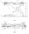
Figure 1 is a perspective view of a lifting device for vehicles realized according to a first preferred configuration. -
Figures 2 and3 represent, respectively, a perspective view and a frontal view of the lifting device ofFigure 1 ; -
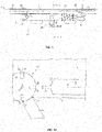
Figure 4 is a top view of the lifting device ofFigure 1 ; -
Figures 5 and 6 represent respective enlargements of details visible in the top view ofFigure 4 . -
Figure 7 represents a further side view of the lifting device ofFigure 1 ; -
Figure 8 is a partial perspective side view of the lifting device ofFigure 7 ; -
Figure 9 is a perspective view of a detail ofFigures 7 and 8 ; -
Figure 10 is a top view of a possible alternative embodiment of the locking means intended to be used in the lifting device ofFigure 1 . - The present invention relates to a lifting device for vehicles which will be indicated in the following description by the
reference number 1. - In particular, the
device 1 can be used to lift road vehicles with different sizes and functions such as, for example, cars, vans, trucks, buses etc. -
Figures 1 to 10 show a preferred embodiment of thelifting device 1 according to the present invention which comprises suitable adaptations and dimensional modifications depending on the size of the vehicle to be raised/lowered (car, truck, bus, caravan, etc.). - The
lifting device 1 comprises astationary structure 2 intended to be placed on the ground S. - As is better visible in
Figures 1 - 3 and inFigure 7 , thestationary structure 2 can consist of asupport base 3 which has a substantially rectangular shape and is designed to be stably anchored to the ground S by means of a plurality of locking screws (not shown in the figures). - Alternatively, the
support base 3 can be embedded inside a special recess made in the floor of the installation environment. - Also provided are a
movable structure 4 operatively connected to thestationary structure 2 and operation means 5 designed to promote the selective and controlled lifting or lowering of themovable structure 4 with respect to thestationary structure 2 between two predetermined limit positions. - As is better visible in
Figures 1 - 4 , themovable structure 4 can comprise aplatform 6 made of a metallic material and having anupper surface 7 which is substantially flat and horizontal. - The
platform 6 is connected to thesupport base 3 by means of two pairs ofparallel side members lower end 10, 10' fixed or hinged to thebase 3 and anupper end 11 hinged to theplatform 6. - In particular, the lower end of a pair of
side members 8 will be hinged to thebase 3 in a fixed position while thelower end 10 of the other pair ofside members 9 is anchored to thebase 3 to be able to translate along a substantially horizontal direction X. - In
Figure 1 andFigure 7 the fixed lower ends of theside members 8 are indicated with thereference number 10 while the lower ends of theside members 9 which can translate along the direction X are indicated with the reference number 10'. - Conveniently, the
lower ends 10, 10' and theupper ends 11 of each side member are arranged on opposite sides with respect to a vertical centerline plane passing through theplatform 6 and indicated in the figures by the symbol π. - The pairs of
side members horizontal crosspiece 12 arranged in a position substantially equidistant from theends 10, 10' and in correspondence with the centerline plane π, as is better visible inFigures 2 and3 . - The operation means 5 comprises a
piston 13 provided with amovable rod 14 whosehead 15 is hinged to abracket 16 which is in turn connected to thecrosspiece 12 in a rotatable manner. - In this way the progressive extension (or return) of the
rod 14 of thepiston 13 allows the counterclockwise (or clockwise) semi-rotation of thebracket 16 by promoting the translational movement of thecrosspiece 12 upwards (or downwards) along the centerline plane π. - The
cylinder 17 of thepiston 13 is constrained to thebase 3 and during its operation the lower end 10' of theside members 9 can translate towards the inside of the base 3 (in the case of a forward movement of the rod 14) or towards the outside of the base 3 (in the case of a return movement of the rod 14). - This way the pairs of
side members - This "X" positioning of the
side members Figures 1 - 7 and in the technical field of lifts and lifting platforms is called a "pantograph" or "scissor" configuration. - Conveniently, the
piston 13 can be of the oleodynamic or pneumatic type and can be replaced by any linear actuator of a different nature (i.e., electrical) adapted to promote the translational and bidirectional movement of a thrust element which can be anchored to thecrosspiece 12. - As described above, during the actuation of the
piston 13, theplatform 6 translates vertically between a lower limit position, in which it is substantially placed in proximity to thesupport base 3, and an upper limit position in which it is placed at a predetermined height from the ground S. - By way of example, in the upper limit position the platform can reach a height h that does not exceed two meters.
- The
lifting device 1 further comprises a plurality ofarms 18 provided with oneend 19 hinged to themovable structure 4 and a freeopposite end 20 to which is associated apad 21 designed to come into contact with the bottom of the vehicle to be lifted. - These
arms 18 are clearly visible inFigures 1 - 5 and inFigure 8 and in this particular configuration of thedevice 1 they are hinged in proximity to the straight side edges 22, 23 of theplatform 6. - The
device 1 typically comprises an even number ofarms 18 uniformly arranged along the side edges 22, 23 of theplatform 6. In the configuration of the device illustrated in the figures the use fourarms 18 distributed in pairs along therespective edges platform 6 is envisaged. - Each
arm 18 is consequently free to selectively rotate around a respective substantially vertical hinge axis Y between an inactive position and an active position. - The
arms 18 can be substantially straight and, in the inactive position (not visible in the figures), they can be collected in proximity of the side edges 22, 23 of theplatform 6 to reduce the overall dimensions of thedevice 1. - When the arms are in the active position, their axis of extension Z can be rotated around the hinge axis Y to perform a predetermined angular movement α with respect to the respective side edges 22, 23 of the
platform 6, as better visible inFigure 4 . - The angle α can be the same for all
arms 18 or can be different for one or more of them. - In other words, the active position can be the same for all the
arms 18 or can vary for one or more arms, according to the requirements. - The rotation of the
arms 18 between the two inactive/active positions can be performed manually by an operator or can be carried out in an automatic or semiautomatic manner through the use of suitable actuators. - The configuration of the invention illustrated in the figures refers to this second case, in which four
small pistons 24 having the bottom of the cylinder hinged to the platform and thehead 25 of the rod hinged to therespective arm 18 are provided. - These pistons are clearly visible in
Figure 7 and Figure 8 . - Conveniently, the
pads 21 can be fixed to thearms 18 in a removable manner and their vertical position with respect to the latter can be manually adjusted by the operator. - In particular, the
upper surface 26 of thepads 21 is intended to come into contact with the bottom of the vehicle and for this reason is located at a height from the ground h' slightly higher than the height h of theplatform 6, generally higher by a few centimetres. - In this way, during the ascent and descent of the vehicle, the vehicle interacts exclusively with the
pads 21 while theplatform 6 is designed to never come into contact with the bottom or with other parts of the means of transport, which is raised with respect to the ground S. - The
pads 21 are generally made of a semi-rigid material suitable for supporting the weight of the vehicle, generally rubber or other similar polymeric materials. - Furthermore, the
pad 21 can be anchored directly to thearm 18 or can be associated with the latter in a removable manner, as better illustrated inFigures 2 ,4 ,5 and8 . - In this case, the
pad 21 is integral with a section of profiled tube 27 (generally having a rectangular cross-section) having aninternal cavity 28 inside which the end portion of thearm 18 can be inserted in a sliding manner. - This condition is clearly visible in
Figures 1 ,8 and5 . - In this way the operator can change the type of
pad 21 to be used for lifting a specific vehicle by simply removing the section oftube 27 in use from thearm 18 and inserting therein the most suitable pad for the specific case. - The section of
tube 27 can be fixed to thearm 18 by means of rapid connection means (for example the insertion of a pin into suitable holes formed on the arm and on the tube) or with other fastening elements known per se and not described in the following description. - According to a particular aspect of the invention, locking means 29 designed to selectively and automatically lock the plurality of
arms 18 when the latter are in the active position are provided. - The presence of the locking means 29 prevents the arms from rotating inadvertently and/or suddenly from their active position during their interaction with the vehicle floor, or during the raising/lowering of the vehicle itself.
- Conveniently, as will be better clarified below, the expression "locking means" used in the present description is intended to refer to means of reversible type, which can be selectively operated to effect both the rotational locking of one or more arms in an active position, as well as the unlocking of the same in order to allow them to rotate from the active position to the inactive position.
- The locking means 29 can be configured to selectively lock one or
more arms 18 in the active position, for example two out of four arms. - Alternatively, the locking means 29 can be configured to selectively lock all
arms 18 in the active position. - Furthermore, in the configuration of the
lifting device 1 illustrated in the figures, the locking means 29 can promote the locking of allarms 18 in the active position substantially in simultaneous, i.e., at the same moment in time. - In the event that a lifting device alternative to the configuration illustrated herein is desired, the locking means 29 can be configured to promote the locking of the
arms 18 at different moments in time, for example one after the other or in accordance with a precise locking sequence. - As better visible in
Figures 4 - 6 , the locking means 29 can comprise a plurality offirst locking elements 30 rigidly connected to the hingedend 19 of arespective arm 18. - The
first locking elements 30 can thus be designed to rotate around the hinge axis Y of thecorresponding arm 18 when a movement between the active position and the inactive position (or vice versa) is conveyed to thearm 18. - In the configuration of the invention illustrated in the figures, the
first locking elements 30 are positioned on the outer surface 31 of the platform, above therespective arm 18. - In particular, the
first locking elements 30 can be manufactured with a plate of reduced thickness and are integral with thehinge pin 32 passing through theend 19 of therespective arm 18. - Conveniently, the locking means 30 comprise a plurality of
second locking elements 33 placed in proximity to thefirst locking elements 30. - Said second locking means 33 are better visible in particular in
Figures 4 - 6 . - Each
first locking element 30 can be associated with a correspondingsecond locking element 33 and the latter can be integral with themovable structure 4. - In the case of the
lifting device 1 illustrated in the figures, the second locking elements are anchored to the upper surface 31 of theplatform 6. - As better shown in
Figures 4 - 6 , thesecond locking element 33 can be obtained from a section of metal profile with a reduced thickness (flat profile). - In particular, each
second locking element 33 can have an elongated shape that extends along a respective direction of extension W substantially horizontal and orthogonal to the hinge axis Y of therespective arm 18. - The
second locking element 33 can be located in proximity of the side edges 22, 23 of theplatform 6 and its extension direction W can be substantially parallel to said edge. - In particular, in the configuration of the
lifting device 1 illustrated in the figures, provision is made for the arrangement of a pair ofsecond locking elements 33 for each side of theplatform 6. - In addition to being positioned in proximity to the
first locking elements 30 which are integral with the respective arm, each pair ofsecond locking elements 33 is arranged to define a single direction W along which bothelements 33 extend. - This configuration is clearly visible in
Figure 4 . - Conveniently, the
first locking elements 30 and thesecond locking elements 33 have respective end edges 34, 35 arranged in a mutually facing position. - Said edges 34, 35 are provided with respective shaped
portions portions edges - As better visible in
Figure 5 and Figure 6 , thefirst locking element 30 has a substantially semicircular edge facing thesecond locking element 33. - Regardless of the active position selected for the
respective arm 18, a toothing 38 (clearly visible inFigure 6 ), the extension of which is chosen so that the teeth are always facing thesecond locking element 33, is formed at aportion 36 of said edge. - In other words, the
toothing 38 performed on theedge portion 36 of thefirst locking element 30 always faces thesecond locking element 33, regardless of the rotation angle α chosen to determine the active position of thecorresponding arm 18. - The
second locking element 33 has anedge portion 37 which is also semicircular and faces thetoothed edge portion 36 of thefirst locking element 30. - Furthermore, the
semicircular edge portion 37 of thesecond locking element 33 has a radius substantially equal to that of the toothedsemicircular edge portion 36 of thefirst locking element 30. - The
edge portion 37 of thesecond locking element 33 likewise includes atoothing 33 the pitch and the shape of the teeth of which is substantially the same as that chosen for thetoothing 38 formed on theedge portion 36 of the first connectingelement 30. - Advantageously, the
first locking element 30 and/or thesecond locking element 33 are movable with respect to each other between a first position and a second position. - In particular, in the first position the
edge portions first locking element 30 and thesecond locking element 33 are spaced apart and disengaged from each other. - In this position the
first locking element 30 can freely rotate around its own hinge axis Y when a rotation is convey to therespective arm 18. - In the second position, the
edge portions second locking element 33. The locking means 29 illustrated inFigures 1 to 9 exhibits locking elements corresponding edge portions - As better visible in
Figure 6 , in the second position thetoothing edge portion second locking element 33 undergo reciprocal meshing thus effecting the rotational locking of therespective arm 18. - In the configuration of the
lifting device 1 indicated in the figures, thefirst locking element 30, although free to rotate with respect to its own hinge axis Y, is constrained with respect to any other movement, including a translation towards thesecond locking element 33. - In other words, the
first locking element 30 is fixed with respect to thesecond locking element 33 inasmuch as it cannot approach or move away from the latter. - The
second locking element 33 is mounted on theplatform 6 in to be free to perform a selective and controlled translation along its extension direction W. - The range of this translation will be such to allow the
edge portion 37 to approach/move away from theedge portion 36 of thefirst locking element 30 so as to move between the first position of disengagement (in which thetoothing elements toothing elements - As better shown
Figure 6 , thesecond locking element 33 includes anelongated seat 40 inside which a fixedpin 41 integral with theplatform 6 is inserted. - During the movement of the
second locking element 33, thepin 41 slides inside theseat 40 to guide the translational movement of the element between the first and second position. - The locking means 29 further comprise at least one
actuator 42 suited to selectively move theedge portion 37 of thesecond locking element 33 between the first position and the second position (and vice versa). - As shown in particular in
Figures 7 - 9 , twopiston type actuators 42 are provided, each of which has a cylinder 43 connected to theplatform 6 and ends (respectively constituted by the head of therod 44 and the bottom 45) connected to the pair ofsecond locking elements 33 arranged along the same side of theplatform 6. - Conveniently, the head of the
rod 44 and the bottom 45 of the actuators are free to translate along a direction substantially parallel to the direction of extension W of thesecond locking element 33. - Furthermore, the head of the
rod 44 and the bottom 45 are arranged on opposite sides with respect to the centerline plane π. - In particular, the ends 44, 45 of the
piston 42 are connected to the end portions of thesecond locking elements 33 by means of ascrew 46 passing through anelongated seat 47 suitably obtained in the platform 6 (clearly visible inFigure 9 ). - The activation of the
actuator 42 will move eachend second locking elements 33 will describe an outward motion to promote the positioning of theiredge portion 37 in the second position (in which the engagement of theteeth - The return of the
ends second locking elements 33 in the opposite direction (i.e. inwards in order to effect their mutual approach). - In this case, therefore, the shaped
edge 37 of thesecond locking elements 33 will move away from the shapededge 36 of thefirst locking elements 30, to the position of disengagement. - In the configuration of the
lifting device 1 illustrated in the figures, asingle actuator 42 can promote the movement of a pair ofsecond locking elements 33 arranged on the same side of theplatform 6. - However, in a different configuration of the
device 1 it is possible to provide for the installation of asingle actuator 42 designed to control the movement of all thesecond locking elements 33 or for the use of a plurality ofactuators 42 that can be operated independently, each being associable with a single connectingelement 33. - Furthermore, the
actuators 42 can be operated simultaneously so as to promote the simultaneous movement of theedge portion 37 of thesecond locking elements 33 into the second position (corresponding to the mutual engagement of thetoothing 38, 39). - Alternatively, the
actuators 42 can be operated at different times to promote theselective engagement elements -
Figure 10 shows a different configuration of theelements - In this case the
edge portions respective locking elements - The
first locking element 30 is in fact provided with a plurality of recesses 48 arranged along radial directrices R which extend starting from the centre of the element (which is placed in correspondence with the hinge axis Y of the respective arm 18). - Each radial directrix R is designed to define a certain active position of the
arm 18, i.e., the angular position of the directrix R defines a corresponding angle of rotation α. - In this case, therefore, the active positions of the
arm 18 are discrete inasmuch as they refer to a predetermined angle of rotation α at which a corresponding recess 48 has been formed on thefirst locking element 30. - The
second locking elements 33 have anelongated edge portion 37 with a shape substantially counter-shaped the recesses 48 formed on thefirst locking element 30. - In the first position the recesses 48 and the
elongated edge portion 37 are spaced apart to allow the rotation of thearm 18 around the hinge axis Y; however in the second position theelongated edge portion 37 of the second connectingelement 33 is inserted inside a corresponding recess 48 formed on theedge 37 of the first connectingelement 30. - This way, the engagement of the locking
elements elongated edge portion 36 inside the recess 48 to lock therespective arm 18 rotationally. - Operationally, when it is necessary to lift the vehicle to a predetermined height, the method for operating the
lifting device 1 is as follows: - a) positioning the
movable structure 4 in the lower limit position (completely lowered); - b) positioning the vehicle above the
movable structure 4; - c) rotation of the
arms 18 from their inactive position to their active position; - d) activating the locking means 29 to promote the locking of one or
more arms 18 in the active position; - e) lifting the
movable structure 4 to bring thepads 21 associated with therespective arms 18 into contact with the bottom of the vehicle to be lifted; - f) further lifting the
movable structure 4 until it reaches the predetermined height above the ground. - In order to promote the lowering of the vehicle, the method for operating the
lifting device 1 is as follows: - g) lowering of the
movable structure 4 down to a height from the ground so as to allow the vehicle wheels to come into contact with the ground; - h) further lowering of the
movable structure 4 to disengage thepads 21 associated with therespective arms 18 from the bottom of the vehicle; - i) activation of the locking means 29 to release the
arms 18 from the active position; - j) rotation of the
arms 18 from the active position to the inactive position. - As described above, the
lifting piston 13, thesmall pistons 24 associated with thearms 18 and theactuators 42 of the locking means 29 can be selected from the various types of components currently available on the market such as, for example, pneumatic, oleodynamic, electrical devices, etc. - If the actuator devices cited above are of a oleodynamic /pneumatic type, it is possible to provide a control unit, indicated in the figures by the
reference number 49, provided with a pump, not illustrated, connected to a circuit directly associated with thelifting piston 13, to thesmall pistons 24 and theactuators 42. - The
lifting device 1 can also comprise an electrical or electronic control unit (not shown) designed to selectively operate the pump and any possible solenoid valves to control the movement of the movable structure 4 (lifting/lowering) and/or the rotation of thearms 18 between the inactive position and the active position. - Conveniently, the
lifting device 1 object of the invention can include shapes and configurations different those shown in the figures, but which are still designed to replicate the inventive concept characterizing the invention. - For example, the
stationary structure 2 can comprise a pair of columns and the movable structure can comprise two distinct parts, each of which is mounted on a respective column to move vertically with respect to the same (in a synchronous manner to the movement of the other moving part). - The present invention can be carried out in other variants, all falling within the scope of the inventive characteristics claimed and described herein; these technical features can be replaced by different technically equivalent elements and materials; the shape and size of the invention can be any, provided that they are compatible with its intended use
- The numbers and reference signs inserted in the claims and in the description have the sole purpose of increasing the clarity of the text, and should not be considered as elements limiting the technical interpretation of the objects or methods identified by the same.
Claims (14)
- A device for lifting vehicles, comprising:- a stationary structure (2) designed to be supported or anchored on the ground (S), or embedded in a recess formed in the floor;- a movable structure (4) operatively connected to said stationary structure (2);- a plurality of arms (18) with one end (19) hinged to said movable structure (2) and a free end (20) with which a pad element (21) designed to come into contact with the vehicle to be lifted is associated;- operation means (5) designed to selectively lift and lower the movable structure (4) with respect to the stationary structure (2) between two predetermined limit positions;- locking means (29) designed to selectively and automatically lock one or more arms (18) of said plurality of arms (18) in the active position;wherein each arm is designed to selectively rotate about a respective substantially vertical hinge axis (Y) between an inactive position and an active position wherein said pad element (21) comes into contact with the vehicle;and wherein said locking means (29) comprise a plurality of first locking elements (30) operatively connected to the hinged end of a respective arm (18),characterized in that said locking means (29) comprise a plurality of second locking elements (33) placed in proximity to said first locking means (30).
- The device according to claim 1, characterized in that said locking means (29) are designed to lock all the arms (18) of said plurality of arms (18) in said active position substantially simultaneously.
- The device according to claim 1 or 2, characterized in that said first locking elements (30) are designed to rotate about the hinge axis (Y) of the corresponding arm (18) when the latter rotates between said active position and said inactive position.
- The device according to one or more of the preceding claims, characterized in that said second locking elements (33) are associated with said movable structure (4).
- The device according to one or more of the preceding claims, characterized in that said first locking elements (30) and said second locking elements (33) have respective end edges (34, 35) facing each other.
- The device according to claim 5, characterized in that said end edges (34, 35) facing each other comprise respective shaped portions (36, 37) having a substantially mutually complementary shape and selected to allow their mutual engagement.
- The device according to one or more of the preceding claims, characterized in that said first locking element (30) and/or said second locking element (33) are reciprocally movable between a first and a second position.
- The device according to claim 7, characterized in that, in said first position, the shaped portions (36, 37) of the end edges (34, 35) of said first (30) and said second locking element (33) are spaced apart and disengaged from each other, and in that, in said second position, the shaped portions (36, 37) of the end edges (34, 35) are substantially in contact and mutually engaged in order to lock said first locking element (30) with respect to said second locking element (33).
- The device according to claim 7 or 8, characterized in that said locking means (29) comprise at list one actuator (42) designed to selectively move the portion (36) of the edge (34) of said first locking element (30) and/or the portion (37) of the edge (35) of said second locking element (33) between said first position and said second position.
- The device according to claim 9, characterized in that said one or more actuators (42) are designed to position the edge portions (36, 37) of the end edges (34, 35) of all the first locking elements (30) and/or all the second locking elements (33) in the second position substantially simultaneously.
- The device according to claim 9, characterized in that said shaped portion (36) of the end edge (34) of said first locking element (30) and said shaped portion (37) of the end edge (35) of said second locking element (33) have a toothing (38, 39) designed to allow mutual engagement of the teeth when the respective arm (18) is in said active position.
- The device according to claim 11, characterized in that each of said second locking elements (33) has an elongated shape extending along a longitudinal extension direction (W) substantially orthogonal to the hinge axis (Y) of the respective arm (18).
- The device according to claim 12, characterized in that the position of the first locking element (30) with respect to the second locking element (33) is substantially fixed, said one or more actuators (42) being designed to move said second locking element (33) along said extension direction (W) to bring its edge portion (37) into said first and into said second position.
- The device according to claim 9, characterized in that said at least one actuator (42) is designed to position all second locking elements (33) in said second position substantially simultaneously.
Applications Claiming Priority (1)
| Application Number | Priority Date | Filing Date | Title |
|---|---|---|---|
| IT102020000024214A IT202000024214A1 (en) | 2020-10-14 | 2020-10-14 | VEHICLE LIFTER DEVICE |
Publications (2)
| Publication Number | Publication Date |
|---|---|
| EP3992141A1 true EP3992141A1 (en) | 2022-05-04 |
| EP3992141B1 EP3992141B1 (en) | 2024-03-06 |
Family
ID=74068474
Family Applications (1)
| Application Number | Title | Priority Date | Filing Date |
|---|---|---|---|
| EP21202520.9A Active EP3992141B1 (en) | 2020-10-14 | 2021-10-13 | Device for lifting vehicles |
Country Status (2)
| Country | Link |
|---|---|
| EP (1) | EP3992141B1 (en) |
| IT (1) | IT202000024214A1 (en) |
Cited By (1)
| Publication number | Priority date | Publication date | Assignee | Title |
|---|---|---|---|---|
| EP4361084A1 (en) * | 2022-10-24 | 2024-05-01 | Herkules Hebetechnik GmbH | A vehicle lifting frame for lifting vehicles |
Citations (3)
| Publication number | Priority date | Publication date | Assignee | Title |
|---|---|---|---|---|
| DE202004008491U1 (en) * | 2004-05-25 | 2004-09-09 | Ochs, Eckhard | Lifting device for motor vehicles has on both sides of elevating platform an overrun plate with a detachable insert within length of approximately one wheel diameter and connected to overrun plate by threaded connection |
| EP1468755A1 (en) | 2003-04-16 | 2004-10-20 | Celette S.A. | Lifting table for vehicles |
| WO2018189137A1 (en) | 2017-04-13 | 2018-10-18 | Finkbeiner, Gerhard | Pivot locking device and lifting device having a pivot locking device |
-
2020
- 2020-10-14 IT IT102020000024214A patent/IT202000024214A1/en unknown
-
2021
- 2021-10-13 EP EP21202520.9A patent/EP3992141B1/en active Active
Patent Citations (3)
| Publication number | Priority date | Publication date | Assignee | Title |
|---|---|---|---|---|
| EP1468755A1 (en) | 2003-04-16 | 2004-10-20 | Celette S.A. | Lifting table for vehicles |
| DE202004008491U1 (en) * | 2004-05-25 | 2004-09-09 | Ochs, Eckhard | Lifting device for motor vehicles has on both sides of elevating platform an overrun plate with a detachable insert within length of approximately one wheel diameter and connected to overrun plate by threaded connection |
| WO2018189137A1 (en) | 2017-04-13 | 2018-10-18 | Finkbeiner, Gerhard | Pivot locking device and lifting device having a pivot locking device |
Cited By (1)
| Publication number | Priority date | Publication date | Assignee | Title |
|---|---|---|---|---|
| EP4361084A1 (en) * | 2022-10-24 | 2024-05-01 | Herkules Hebetechnik GmbH | A vehicle lifting frame for lifting vehicles |
Also Published As
| Publication number | Publication date |
|---|---|
| IT202000024214A1 (en) | 2022-04-14 |
| EP3992141B1 (en) | 2024-03-06 |
Similar Documents
| Publication | Publication Date | Title |
|---|---|---|
| EP3992141A1 (en) | Device for lifting vehicles | |
| US8469152B2 (en) | Methods and systems for multi-capacity vehicle lift system | |
| US20100243973A1 (en) | Scissor-type lifting platform | |
| US20040069979A1 (en) | Anti fall device | |
| CN109382805B (en) | Work support device capable of freely lifting | |
| US20070235266A1 (en) | Low profile lift | |
| US20120145480A1 (en) | Ladder Deployment System | |
| US7143869B1 (en) | Hydraulic vehicle lift | |
| US5388947A (en) | Manually controlled vehicle restraint apparatus with a counterbalance | |
| US5025892A (en) | Portable lift for lifting motor vehicles | |
| EP3227225B1 (en) | Stabilizer arrangement | |
| EP2974995B1 (en) | Apparatus for supporting a wheel of a vehicle | |
| EP2706035B1 (en) | Hydraulic jack with mechanical locking system | |
| WO2000043302A1 (en) | Container restraint for a parked swap body | |
| US7207419B2 (en) | Safety lock system for a lift | |
| US5613575A (en) | Flat-structure lifting platform | |
| JPH04502745A (en) | car lifting equipment | |
| US4548387A (en) | Mobile hoist | |
| EP3031757A1 (en) | Dock leveler safety supports | |
| KR920001419Y1 (en) | Mechanism for automatically preventing a motor vehicle from dropping from a wheels support plate of a system for lifting the vehicle for repair thereof | |
| JP2009511396A (en) | Lift-type mounting table with torsion bar | |
| CN109591708B (en) | Electric pedal device and off-road vehicle | |
| EP3345861B1 (en) | Lifting device for lifting a vehicle with a locking system and lifting system and method therefor | |
| EP3620421A1 (en) | Lifting equipment for the reparation of post-collision, damaged or under maintenance vehicles | |
| KR20020043102A (en) | Lift-apparatus for automobile |
Legal Events
| Date | Code | Title | Description |
|---|---|---|---|
| PUAI | Public reference made under article 153(3) epc to a published international application that has entered the european phase |
Free format text: ORIGINAL CODE: 0009012 |
|
| STAA | Information on the status of an ep patent application or granted ep patent |
Free format text: STATUS: THE APPLICATION HAS BEEN PUBLISHED |
|
| AK | Designated contracting states |
Kind code of ref document: A1 Designated state(s): AL AT BE BG CH CY CZ DE DK EE ES FI FR GB GR HR HU IE IS IT LI LT LU LV MC MK MT NL NO PL PT RO RS SE SI SK SM TR |
|
| STAA | Information on the status of an ep patent application or granted ep patent |
Free format text: STATUS: REQUEST FOR EXAMINATION WAS MADE |
|
| 17P | Request for examination filed |
Effective date: 20221103 |
|
| RBV | Designated contracting states (corrected) |
Designated state(s): AL AT BE BG CH CY CZ DE DK EE ES FI FR GB GR HR HU IE IS IT LI LT LU LV MC MK MT NL NO PL PT RO RS SE SI SK SM TR |
|
| P01 | Opt-out of the competence of the unified patent court (upc) registered |
Effective date: 20230531 |
|
| GRAP | Despatch of communication of intention to grant a patent |
Free format text: ORIGINAL CODE: EPIDOSNIGR1 |
|
| STAA | Information on the status of an ep patent application or granted ep patent |
Free format text: STATUS: GRANT OF PATENT IS INTENDED |
|
| INTG | Intention to grant announced |
Effective date: 20231218 |
|
| GRAS | Grant fee paid |
Free format text: ORIGINAL CODE: EPIDOSNIGR3 |
|
| GRAA | (expected) grant |
Free format text: ORIGINAL CODE: 0009210 |
|
| STAA | Information on the status of an ep patent application or granted ep patent |
Free format text: STATUS: THE PATENT HAS BEEN GRANTED |
|
| AK | Designated contracting states |
Kind code of ref document: B1 Designated state(s): AL AT BE BG CH CY CZ DE DK EE ES FI FR GB GR HR HU IE IS IT LI LT LU LV MC MK MT NL NO PL PT RO RS SE SI SK SM TR |
|
| REG | Reference to a national code |
Ref country code: CH Ref legal event code: EP |
|
| REG | Reference to a national code |
Ref country code: DE Ref legal event code: R096 Ref document number: 602021010060 Country of ref document: DE |
|
| REG | Reference to a national code |
Ref country code: IE Ref legal event code: FG4D |