EP3992032A1 - Work vehicle - Google Patents
Work vehicle Download PDFInfo
- Publication number
- EP3992032A1 EP3992032A1 EP20830590.4A EP20830590A EP3992032A1 EP 3992032 A1 EP3992032 A1 EP 3992032A1 EP 20830590 A EP20830590 A EP 20830590A EP 3992032 A1 EP3992032 A1 EP 3992032A1
- Authority
- EP
- European Patent Office
- Prior art keywords
- indicator light
- speed
- driving
- control unit
- indicator
- Prior art date
- Legal status (The legal status is an assumption and is not a legal conclusion. Google has not performed a legal analysis and makes no representation as to the accuracy of the status listed.)
- Pending
Links
- 238000003860 storage Methods 0.000 claims description 21
- 230000007246 mechanism Effects 0.000 description 11
- 230000005540 biological transmission Effects 0.000 description 7
- 239000012530 fluid Substances 0.000 description 7
- 230000007935 neutral effect Effects 0.000 description 7
- 230000007480 spreading Effects 0.000 description 6
- 238000003892 spreading Methods 0.000 description 6
- 230000008859 change Effects 0.000 description 5
- 244000025254 Cannabis sativa Species 0.000 description 4
- 238000004590 computer program Methods 0.000 description 3
- 230000009471 action Effects 0.000 description 2
- 239000003337 fertilizer Substances 0.000 description 2
- 238000012423 maintenance Methods 0.000 description 2
- 238000004519 manufacturing process Methods 0.000 description 2
- 238000000034 method Methods 0.000 description 2
- 238000012986 modification Methods 0.000 description 2
- 230000004048 modification Effects 0.000 description 2
- 239000000575 pesticide Substances 0.000 description 2
- 238000002485 combustion reaction Methods 0.000 description 1
- 238000004891 communication Methods 0.000 description 1
- 238000010586 diagram Methods 0.000 description 1
- 238000006073 displacement reaction Methods 0.000 description 1
- 230000000694 effects Effects 0.000 description 1
- 238000003306 harvesting Methods 0.000 description 1
Images




Classifications
-
- B—PERFORMING OPERATIONS; TRANSPORTING
- B62—LAND VEHICLES FOR TRAVELLING OTHERWISE THAN ON RAILS
- B62D—MOTOR VEHICLES; TRAILERS
- B62D49/00—Tractors
-
- B—PERFORMING OPERATIONS; TRANSPORTING
- B60—VEHICLES IN GENERAL
- B60Q—ARRANGEMENT OF SIGNALLING OR LIGHTING DEVICES, THE MOUNTING OR SUPPORTING THEREOF OR CIRCUITS THEREFOR, FOR VEHICLES IN GENERAL
- B60Q1/00—Arrangement of optical signalling or lighting devices, the mounting or supporting thereof or circuits therefor
- B60Q1/26—Arrangement of optical signalling or lighting devices, the mounting or supporting thereof or circuits therefor the devices being primarily intended to indicate the vehicle, or parts thereof, or to give signals, to other traffic
- B60Q1/30—Arrangement of optical signalling or lighting devices, the mounting or supporting thereof or circuits therefor the devices being primarily intended to indicate the vehicle, or parts thereof, or to give signals, to other traffic for indicating rear of vehicle, e.g. by means of reflecting surfaces
- B60Q1/305—Indicating devices for towed vehicles
-
- B—PERFORMING OPERATIONS; TRANSPORTING
- B60—VEHICLES IN GENERAL
- B60Q—ARRANGEMENT OF SIGNALLING OR LIGHTING DEVICES, THE MOUNTING OR SUPPORTING THEREOF OR CIRCUITS THEREFOR, FOR VEHICLES IN GENERAL
- B60Q1/00—Arrangement of optical signalling or lighting devices, the mounting or supporting thereof or circuits therefor
- B60Q1/26—Arrangement of optical signalling or lighting devices, the mounting or supporting thereof or circuits therefor the devices being primarily intended to indicate the vehicle, or parts thereof, or to give signals, to other traffic
- B60Q1/34—Arrangement of optical signalling or lighting devices, the mounting or supporting thereof or circuits therefor the devices being primarily intended to indicate the vehicle, or parts thereof, or to give signals, to other traffic for indicating change of drive direction
- B60Q1/346—Arrangement of optical signalling or lighting devices, the mounting or supporting thereof or circuits therefor the devices being primarily intended to indicate the vehicle, or parts thereof, or to give signals, to other traffic for indicating change of drive direction with automatic actuation
-
- B—PERFORMING OPERATIONS; TRANSPORTING
- B60—VEHICLES IN GENERAL
- B60Q—ARRANGEMENT OF SIGNALLING OR LIGHTING DEVICES, THE MOUNTING OR SUPPORTING THEREOF OR CIRCUITS THEREFOR, FOR VEHICLES IN GENERAL
- B60Q1/00—Arrangement of optical signalling or lighting devices, the mounting or supporting thereof or circuits therefor
- B60Q1/26—Arrangement of optical signalling or lighting devices, the mounting or supporting thereof or circuits therefor the devices being primarily intended to indicate the vehicle, or parts thereof, or to give signals, to other traffic
- B60Q1/34—Arrangement of optical signalling or lighting devices, the mounting or supporting thereof or circuits therefor the devices being primarily intended to indicate the vehicle, or parts thereof, or to give signals, to other traffic for indicating change of drive direction
- B60Q1/38—Arrangement of optical signalling or lighting devices, the mounting or supporting thereof or circuits therefor the devices being primarily intended to indicate the vehicle, or parts thereof, or to give signals, to other traffic for indicating change of drive direction using immovably-mounted light sources, e.g. fixed flashing lamps
-
- B—PERFORMING OPERATIONS; TRANSPORTING
- B60—VEHICLES IN GENERAL
- B60Q—ARRANGEMENT OF SIGNALLING OR LIGHTING DEVICES, THE MOUNTING OR SUPPORTING THEREOF OR CIRCUITS THEREFOR, FOR VEHICLES IN GENERAL
- B60Q1/00—Arrangement of optical signalling or lighting devices, the mounting or supporting thereof or circuits therefor
- B60Q1/26—Arrangement of optical signalling or lighting devices, the mounting or supporting thereof or circuits therefor the devices being primarily intended to indicate the vehicle, or parts thereof, or to give signals, to other traffic
- B60Q1/46—Arrangement of optical signalling or lighting devices, the mounting or supporting thereof or circuits therefor the devices being primarily intended to indicate the vehicle, or parts thereof, or to give signals, to other traffic for giving flashing caution signals during drive, other than signalling change of direction, e.g. flashing the headlights or hazard lights
-
- B—PERFORMING OPERATIONS; TRANSPORTING
- B60—VEHICLES IN GENERAL
- B60Q—ARRANGEMENT OF SIGNALLING OR LIGHTING DEVICES, THE MOUNTING OR SUPPORTING THEREOF OR CIRCUITS THEREFOR, FOR VEHICLES IN GENERAL
- B60Q11/00—Arrangement of monitoring devices for devices provided for in groups B60Q1/00 - B60Q9/00
- B60Q11/005—Arrangement of monitoring devices for devices provided for in groups B60Q1/00 - B60Q9/00 for lighting devices, e.g. indicating if lamps are burning or not
- B60Q11/007—Arrangement of monitoring devices for devices provided for in groups B60Q1/00 - B60Q9/00 for lighting devices, e.g. indicating if lamps are burning or not the lighting devices indicating change of drive direction
-
- B—PERFORMING OPERATIONS; TRANSPORTING
- B60—VEHICLES IN GENERAL
- B60Q—ARRANGEMENT OF SIGNALLING OR LIGHTING DEVICES, THE MOUNTING OR SUPPORTING THEREOF OR CIRCUITS THEREFOR, FOR VEHICLES IN GENERAL
- B60Q9/00—Arrangement or adaptation of signal devices not provided for in one of main groups B60Q1/00 - B60Q7/00, e.g. haptic signalling
-
- B—PERFORMING OPERATIONS; TRANSPORTING
- B60—VEHICLES IN GENERAL
- B60W—CONJOINT CONTROL OF VEHICLE SUB-UNITS OF DIFFERENT TYPE OR DIFFERENT FUNCTION; CONTROL SYSTEMS SPECIALLY ADAPTED FOR HYBRID VEHICLES; ROAD VEHICLE DRIVE CONTROL SYSTEMS FOR PURPOSES NOT RELATED TO THE CONTROL OF A PARTICULAR SUB-UNIT
- B60W10/00—Conjoint control of vehicle sub-units of different type or different function
- B60W10/04—Conjoint control of vehicle sub-units of different type or different function including control of propulsion units
- B60W10/06—Conjoint control of vehicle sub-units of different type or different function including control of propulsion units including control of combustion engines
-
- B—PERFORMING OPERATIONS; TRANSPORTING
- B60—VEHICLES IN GENERAL
- B60W—CONJOINT CONTROL OF VEHICLE SUB-UNITS OF DIFFERENT TYPE OR DIFFERENT FUNCTION; CONTROL SYSTEMS SPECIALLY ADAPTED FOR HYBRID VEHICLES; ROAD VEHICLE DRIVE CONTROL SYSTEMS FOR PURPOSES NOT RELATED TO THE CONTROL OF A PARTICULAR SUB-UNIT
- B60W10/00—Conjoint control of vehicle sub-units of different type or different function
- B60W10/30—Conjoint control of vehicle sub-units of different type or different function including control of auxiliary equipment, e.g. air-conditioning compressors or oil pumps
-
- B—PERFORMING OPERATIONS; TRANSPORTING
- B60—VEHICLES IN GENERAL
- B60W—CONJOINT CONTROL OF VEHICLE SUB-UNITS OF DIFFERENT TYPE OR DIFFERENT FUNCTION; CONTROL SYSTEMS SPECIALLY ADAPTED FOR HYBRID VEHICLES; ROAD VEHICLE DRIVE CONTROL SYSTEMS FOR PURPOSES NOT RELATED TO THE CONTROL OF A PARTICULAR SUB-UNIT
- B60W30/00—Purposes of road vehicle drive control systems not related to the control of a particular sub-unit, e.g. of systems using conjoint control of vehicle sub-units
- B60W30/18—Propelling the vehicle
- B60W30/18009—Propelling the vehicle related to particular drive situations
-
- B—PERFORMING OPERATIONS; TRANSPORTING
- B60—VEHICLES IN GENERAL
- B60Q—ARRANGEMENT OF SIGNALLING OR LIGHTING DEVICES, THE MOUNTING OR SUPPORTING THEREOF OR CIRCUITS THEREFOR, FOR VEHICLES IN GENERAL
- B60Q2800/00—Features related to particular types of vehicles not otherwise provided for
- B60Q2800/20—Utility vehicles, e.g. for agriculture, construction work
-
- B—PERFORMING OPERATIONS; TRANSPORTING
- B60—VEHICLES IN GENERAL
- B60W—CONJOINT CONTROL OF VEHICLE SUB-UNITS OF DIFFERENT TYPE OR DIFFERENT FUNCTION; CONTROL SYSTEMS SPECIALLY ADAPTED FOR HYBRID VEHICLES; ROAD VEHICLE DRIVE CONTROL SYSTEMS FOR PURPOSES NOT RELATED TO THE CONTROL OF A PARTICULAR SUB-UNIT
- B60W2300/00—Indexing codes relating to the type of vehicle
- B60W2300/15—Agricultural vehicles
- B60W2300/152—Tractors
-
- B—PERFORMING OPERATIONS; TRANSPORTING
- B60—VEHICLES IN GENERAL
- B60W—CONJOINT CONTROL OF VEHICLE SUB-UNITS OF DIFFERENT TYPE OR DIFFERENT FUNCTION; CONTROL SYSTEMS SPECIALLY ADAPTED FOR HYBRID VEHICLES; ROAD VEHICLE DRIVE CONTROL SYSTEMS FOR PURPOSES NOT RELATED TO THE CONTROL OF A PARTICULAR SUB-UNIT
- B60W2510/00—Input parameters relating to a particular sub-units
- B60W2510/10—Change speed gearings
-
- B—PERFORMING OPERATIONS; TRANSPORTING
- B60—VEHICLES IN GENERAL
- B60W—CONJOINT CONTROL OF VEHICLE SUB-UNITS OF DIFFERENT TYPE OR DIFFERENT FUNCTION; CONTROL SYSTEMS SPECIALLY ADAPTED FOR HYBRID VEHICLES; ROAD VEHICLE DRIVE CONTROL SYSTEMS FOR PURPOSES NOT RELATED TO THE CONTROL OF A PARTICULAR SUB-UNIT
- B60W2510/00—Input parameters relating to a particular sub-units
- B60W2510/30—Auxiliary equipments
-
- B—PERFORMING OPERATIONS; TRANSPORTING
- B60—VEHICLES IN GENERAL
- B60W—CONJOINT CONTROL OF VEHICLE SUB-UNITS OF DIFFERENT TYPE OR DIFFERENT FUNCTION; CONTROL SYSTEMS SPECIALLY ADAPTED FOR HYBRID VEHICLES; ROAD VEHICLE DRIVE CONTROL SYSTEMS FOR PURPOSES NOT RELATED TO THE CONTROL OF A PARTICULAR SUB-UNIT
- B60W2530/00—Input parameters relating to vehicle conditions or values, not covered by groups B60W2510/00 or B60W2520/00
- B60W2530/203—Presence of trailer
-
- B—PERFORMING OPERATIONS; TRANSPORTING
- B60—VEHICLES IN GENERAL
- B60W—CONJOINT CONTROL OF VEHICLE SUB-UNITS OF DIFFERENT TYPE OR DIFFERENT FUNCTION; CONTROL SYSTEMS SPECIALLY ADAPTED FOR HYBRID VEHICLES; ROAD VEHICLE DRIVE CONTROL SYSTEMS FOR PURPOSES NOT RELATED TO THE CONTROL OF A PARTICULAR SUB-UNIT
- B60W2540/00—Input parameters relating to occupants
- B60W2540/06—Ignition switch
-
- B—PERFORMING OPERATIONS; TRANSPORTING
- B60—VEHICLES IN GENERAL
- B60W—CONJOINT CONTROL OF VEHICLE SUB-UNITS OF DIFFERENT TYPE OR DIFFERENT FUNCTION; CONTROL SYSTEMS SPECIALLY ADAPTED FOR HYBRID VEHICLES; ROAD VEHICLE DRIVE CONTROL SYSTEMS FOR PURPOSES NOT RELATED TO THE CONTROL OF A PARTICULAR SUB-UNIT
- B60W2710/00—Output or target parameters relating to a particular sub-units
- B60W2710/06—Combustion engines, Gas turbines
-
- B—PERFORMING OPERATIONS; TRANSPORTING
- B60—VEHICLES IN GENERAL
- B60W—CONJOINT CONTROL OF VEHICLE SUB-UNITS OF DIFFERENT TYPE OR DIFFERENT FUNCTION; CONTROL SYSTEMS SPECIALLY ADAPTED FOR HYBRID VEHICLES; ROAD VEHICLE DRIVE CONTROL SYSTEMS FOR PURPOSES NOT RELATED TO THE CONTROL OF A PARTICULAR SUB-UNIT
- B60W2710/00—Output or target parameters relating to a particular sub-units
- B60W2710/30—Auxiliary equipments
-
- B—PERFORMING OPERATIONS; TRANSPORTING
- B60—VEHICLES IN GENERAL
- B60W—CONJOINT CONTROL OF VEHICLE SUB-UNITS OF DIFFERENT TYPE OR DIFFERENT FUNCTION; CONTROL SYSTEMS SPECIALLY ADAPTED FOR HYBRID VEHICLES; ROAD VEHICLE DRIVE CONTROL SYSTEMS FOR PURPOSES NOT RELATED TO THE CONTROL OF A PARTICULAR SUB-UNIT
- B60W2756/00—Output or target parameters relating to data
- B60W2756/10—Involving external transmission of data to or from the vehicle
-
- B—PERFORMING OPERATIONS; TRANSPORTING
- B62—LAND VEHICLES FOR TRAVELLING OTHERWISE THAN ON RAILS
- B62D—MOTOR VEHICLES; TRAILERS
- B62D49/00—Tractors
- B62D49/06—Tractors adapted for multi-purpose use
Definitions
- the present invention relates to a working vehicle.
- Patent Document 1 is a technique for displaying an indicator light in a working machine such as a tractor.
- the working machine of Patent Document 1 includes a signal generating unit configured to generate a flash signal for at least flashing a pair of indicator lights, and a priority setting unit configured to prioritize either a flashing action of the indicator lights based on an operation of a directional instruction tool or another flashing action of the indicator lights based on an operation of a hazard instruction tool. And, a switching unit configured to turns on or off the pair of indicator lights based on a control signal from the priority setting unit is connected to the signal generating unit and the pair of indicator lights therebetween.
- Patent document 1 Japanese Unexamined Patent Publication No. 2015-189358
- Patent Document 1 either a setting for hazard priority or another setting for directional indicator priority can be adopted according to a destination for export.
- the setting for hazard priority or the other setting for directional indicator priority can be adopted according to a destination for export in Patent Document 1; however, if specifications for the destination are changed or if specifications other than that of the indicator lights are differed according to destinations for export, it causes a problem that various modifications have to be made, such as changing of connections between harnesses or setting of conditions.
- the present invention intends to provide a working vehicle capable of being easily adapted to a destination for export.
- a working vehicle includes a prime mover provided on a vehicle body, a first indicator light provided on the vehicle body, a second indicator light provided on a working device connected to the vehicle body, and an integrated controller including a first control unit to control the prime mover, and a second control unit to control the first indicator light and the second indicator light.
- the integrated controller includes a storage unit to store a driving condition required for the first control unit to drive the prime mover, and a lighting condition required for the second control unit to either light or extinguish each of the first indicator light and the second indicator light.
- the working vehicle further includes a connection section configured so that an external terminal for storing setting data including the driving condition and the lighting condition can be connected to the connection section.
- the integrated controller is configured or programmed to make the storage unit store the setting data when the setting data is transmitted from the external terminal to the integrated controller via the connection section and when combination of the driving condition and the lighting condition in the transmitted setting data coincides to a predetermined combination of the driving condition and the lighting condition.
- the working vehicle further includes an ignition switch configured to perform starting of the prime mover, a speed-changing device configured to perform speed-changing of the vehicle body in traveling, and a PTO driving device configured to be driven by power from the prime mover and transmit a driving force thereof to the working device.
- the first control unit is configured or programmed to drive the prime mover when a switching state of the ignition switch, a speed-changing state of the speed-changing device and a driving state of the PTO driving device coincide to those defined as the driving condition.
- the working vehicle further includes a directional indicator switch operable to flash the first and second indicator lights for direction indication, and a hazard switch operable to flash the first and second indicator lights for hazard indication.
- the second control unit is configured or programmed to flash each of the first and second indicator lights when an operation state of the directional indicator switch and an operation state of the hazard switch coincide to those defined as the driving condition.
- the storage unit previously stores a first disconnection judgment condition required to determine the first indicator light as being disconnected and a second disconnection judgment condition required to determine the second indicator light as being disconnected.
- the second control unit is configured or programmed to determine the first indicator light as being disconnected when the first indicator light is found as being in the first disconnection judgment condition, and to determine the second indicator light as being disconnected when the second indicator light is found as being in the second disconnection judgment condition.
- the integrated controller includes a single casing.
- Fig. 7 shows a side view of a working vehicle 1 according to an embodiment
- Fig. 7 shows a plan view of the working vehicle 1 according to the embodiment
- the working vehicle 1 is a tractor.
- the working vehicle 1 is not limited to the tractor, and may be an agricultural machine (agricultural vehicle) such as a combine harvester or a transplanter.
- a forward direction from a driver sitting on a driver's seat 10 of the tractor (working vehicle) 1 is described as the front
- a backward direction from the driver is described as the rear
- a leftward direction from the driver is described as the left
- a rightward direction from the driver is described as the right.
- a horizontal direction which is a direction orthogonal to a fore-and-aft direction of the working vehicle 1, is described as a width direction in a vehicle body.
- the tractor 1 includes a vehicle body 3 having a traveling device 7, a prime mover 4, and a speed-changing device 5.
- the traveling device 7 is a device having front wheels 7F and rear wheels 7R.
- the front wheels 7F may be tire types or crawler types.
- the rear wheels R7 may be tire types or crawler types.
- the prime mover 4 is an internal combustion engine such as a gasoline engine or diesel engine, an electric motor, or the like. In this embodiment, the prime mover 4 is a diesel engine.
- the speed-changing device 5 is capable of changing a speed of rotary force for propelling the traveling device 7, and is capable of switching the traveling direction of the traveling device 7 to forward or backward.
- a cabin 9 is provided on the vehicle body 3, and a driver's seat 10 is provided in the cabin 9.
- a lifting device 8 is disposed at a rear portion of the vehicle body 3.
- the working device 2 can be attached to and detached from the lifting device 8.
- the lifting device 8 can raise and lower the working device 2 attached thereto.
- the working device 2 is a cultivating device for cultivation, a fertilizer spreading device for spreading fertilizer, a pesticide spreading device for spreading pesticide, a harvester for harvesting, a mowing device for mowing grass or the like, a spreading device for spreading the grass or the like, a raking device for raking the grass or the like, a baling device for baling the grass or the like, a trailer for transporting, or the like.
- the vehicle body 3 of the tractor 1 has a first indicator light 31.
- the first indicator light 31 is a lamp configured to light, be extinguished, and flash.
- the first indicator light 31 includes a first left indicator light 31L disposed on a left portion of the vehicle body 3 and a first right indicator light 31R disposed on a right portion of the vehicle body 3.
- a second indicator light 32 is provided on the working device 2.
- the second indicator light 32 is a lamp configured to light, be extinguished, and flash.
- the second indicator light 32 includes a second left indicator light 32L disposed on a left portion of the working device 2 and a second right indicator light 32R disposed on a right portion of the working device 2.
- the speed-changing device 5 includes a main shaft (propulsion shaft) 5a, a shuttle unit 5b, a main speed-changing unit 5c, a sub speed-changing unit 5d, a PTO power transmission unit 5e, and a front speed-changing unit 5f.
- the propulsion shaft 5a is rotatably supported by a housing case of the speed-changing device 5, and a power from the crankshaft of the prime mover 4 is transmitted to the propulsion shaft 5a.
- the shuttle unit 5b includes a shuttle shaft 5b1 and a forward /backward-traveling switching unit 5b2.
- a power from the propulsion shaft 5a is transmitted to the shuttle shaft 5b1.
- the forward/backward-traveling switching unit 5b2 is constituted of, for example, a hydraulic clutch or the like, and is configured to switch, through engagement and disengagement of the hydraulic clutch, a rotational direction of the shuttle shaft 5b1, i.e., a traveling direction of the tractor 1 between the forward traveling and the backward traveling.
- the main speed-changing unit 5c is a continuously variable speed-changing mechanism that changes the input power in a stepless manner.
- the continuously variable speed-changing mechanism includes a hydraulic pump 5c1, a hydraulic motor 5c2, and a planetary gear mechanism 5c3.
- the hydraulic pump 5c1 is rotated by a power from an output shaft 5b3 of the shuttle unit 5b.
- the hydraulic pump 5c1 is, for example, a variable displacement pump including a swash plate 12, and is configured to change an angle of the swash plate 12 (swash plate angle) to change a flow rate of hydraulic fluid delivered from the hydraulic pump 5c1.
- the hydraulic motor 5c2 is a motor configured to be rotated by the hydraulic fluid delivered from the hydraulic pump 5c1 through a hydraulic circuit such as piping. A rotation speed of the hydraulic motor 5c2 can be changed by changing the swash plate angle of the hydraulic pump 5c1 or by changing a power to be input to the hydraulic pump 5c1.
- the planetary gear mechanism 5c3 is a mechanism that includes a plurality of gears (toothed wheels) and power transmission shafts including an input shaft and an output shaft, and includes an input shaft 13 to which a power of the hydraulic pump 5c1 is input, an input shaft 14 to which a power of the hydraulic motor 5c2 is input, and an output shaft 15 from which the power is output.
- the planetary gear mechanism 5c3 combines the powers of the hydraulic pump 5c1 and the hydraulic motor 5c2 and then transmits the combined power to the output shaft 15.
- the power to be output to the sub speed-changing unit 5d can be changed by changing the swash plate angle of the swash plate 12 of the hydraulic pump 5c1, a rotation speed of the prime mover 4, and the like.
- the main speed-changing unit 5c is a continuously variable speed-changing mechanism.
- the main speed-changing unit 5c may be a stepped speed-changing mechanism including gears to change the speed.
- the sub speed-changing unit 5d is a speed-changing mechanism including a plurality of stepped-speed gears (toothed wheels) for speed-shifting the transmitted power, and selects appropriate gears to be drivingly connected (engaged) among the plurality of gears to change (that is, speed-change) the power input from the output shaft 15 of the planetary gear mechanism 5c3 and output the speed-changed power to the sub speed-changing unit 5d.
- the sub speed-changing unit 5d includes an input shaft 5d1, a first speed-changing clutch 5d2, a second speed-changing clutch 5d3, and an output shaft 5d4.
- the input shaft 5d1 is a shaft to which the power of the output shaft 15 of the planetary gear mechanism 5c3 is input, and inputs the input power to the first speed-changing clutch 5d2 and the second speed-changing clutch 5d3 through the gears or the like.
- the power output to the output shaft 5d4 is transmitted to a rear-wheel differential device 20R.
- the rear-wheel differential device 20R rotatably supports rear axles 21R to which the rear wheels 7R are attached.
- the PTO power transmission unit (PTO driving unit) 5e includes a PTO clutch 5e1, a PTO propulsion shaft 5e2, and a PTO speed-changing unit 5e3.
- the PTO clutch 5e1 is, for example, constituted of a hydraulic clutch or the like, and is shifted, through engagement and disengagement of the hydraulic clutch, between a state (engaged state) in which the power of the propulsion shaft 5a is transmitted to the PTO propulsion shaft 5e2 and a state (disengaged state) in which the power of the propulsion shaft 5a is not transmitted to the PTO propulsion shaft 5e2.
- the PTO speed-changing unit 5e3 includes a speed-changing clutch, a plurality of gears, and the like, and speed-changes the power (rotation speed) input from the PTO propulsion shaft 5e2 outputs the speed-changed power to the PTO speed-changing unit 5e3.
- the power of the PTO transmission 5e3 is transmitted to the PTO shaft 16 through gears and the like.
- the front speed-changing unit 5f includes a first front speed-changing clutch 5f1 and a second front speed-changing clutch 5f2.
- the first front speed-changing clutch 5f1 and the second front speed-changing clutch 5f2 are capable of transmitting the power from the sub speed-changing unit 5d, and the power of the output shaft 5d4 is transmitted through gears and a transmission shaft, for example.
- the powers from the first front speed-changing clutch 5f1 and the second front speed-changing clutch 5f2 can be transmitted to front axles 21F via a front transmission shaft 22.
- the front transmission shaft 22 is connected to the front wheel differential device 20F, and the front wheel differential device 20F rotatably supports the front axles 21F to which the front wheels 7F are attached.
- Each of the first front speed-changing clutch 5f1 and the second front speed-changing clutch 5f2 is constituted of a hydraulic clutch or the like.
- a fluid passage is connected to the first front speed-changing clutch 5f1, and the fluid passage is connected to a control valve to which hydraulic fluid delivered from the hydraulic pump is supplied.
- the first front speed-changing clutch 5f1 is shifted between the engaged state and the disengaged state according to an opening degree of the control valve.
- a fluid passage is connected to the second front speed-changing clutch 5f2, and the fluid passage is connected to a control valve.
- the second front speed-changing clutch 5f2 is shifted between the engaged state and the disengaged state according to an opening degree of the control valve.
- Each of the control valves is, for example, a two-position switching valve with a solenoid valve, which is shifted to the engaged state or disengaged state when magnetizing or demagnetizing each of solenoids of the solenoid valves.
- the tractor 1 includes an integrated controller 40.
- the integrated controller 40 is a unit integrating a control unit that controls the prime mover 4 and a control unit that controls the first indicator light 31 and the second indicator light 32, and includes a single casing incorporating these components.
- the integrated controller 40 is constituted of a CPU, an electric/electronic circuit, and the like, and stores predetermined computer programs.
- An ignition switch 41, a parking switch 42, a speed-changing switch 43, a PTO switch 44, a seat switch 45, and a notification device 46 are connected to the integrated controller 40.
- the ignition switch 41, the parking switch 42, the speed-changing switch 43, and the PTO switch 44 are switches that can be operated by a driver.
- the ignition switch 41 is operable at least to be turned on or off, The ignition switch 41 is turned on when the prime mover 4 is to be driven, and is turned off when the driving of the prime mover 4 is to be stopped.
- the parking switch 42 is a switch configured to detect parking of the traveling vehicle body (vehicle body) 3. Specifically, the parking switch 42 is operable to be turned on or off. When a parking lever (parking brake), which is swingably supported by the vehicle body 3, is shifted to a position (braking position) for braking the vehicle body 3, the parking switch 42 is turned on according to swinging of the parking lever to detect the parking. When the parking lever is shifted to a position (releasing position) for releasing the braking of the vehicle body 3, the parking switch 42 is turned off according to swinging of the parking lever and does not detect the parking.
- the speed-changing switch 43 is a switch capable of detecting at least a neutral state (neutral position). In this regard, the speed-changing switch 43 is turned on when the speed-changing lever is in the neutral position, and is turned off when the speed-changing lever is in a position other than the neutral position.
- the PTO switch 44 is operable to be turned on or off to selectively allow or disable the driving of the PTO shaft 16. For example, when the PTO switch 44 is turned on, the driving of the PTO shaft 16 is in an "allowed state", and when the PTO switch 44 is turned off, the driving of the PTO shaft 16 is in a "disabled state”. When the PTO switch 44 is turned on, the PTO clutch 5e1 enters the engaged state, and the PTO shaft 16 is driven (rotated). On the other hand, when the PTO switch 44 is turned off, the PTO clutch 5e1 enters the disengaged state, and the driving (rotation) of the PTO shaft 16 stops.
- the seat switch 45 is a switch configured to detect that a driver is sitting on the driver's seat 10.
- the seat switch 45 is operable to be turned on or off.
- the seat switch 45 is disposed in a portion (seating portion, backrest) of the driver's seat 6, or below the seat or the like. When the driver sits on the seat to contact the portion, the seat switch 45 is turned on to detect the seating. In addition, when the driver leaves the seat to be separated from the portion, the seat switch 45 is turned off to detect that the driver is not sitting on the seat.
- the notification device 46 is a monitor on which various information can be displayed, a light source lamp such as an LED, a speaker that generates a warning sound, or the like. Only when a predetermined condition is satisfied, the notification device 46 issues a warning to be displayed on the monitor, a warning as lighting and flashing the light source lamp, or a warning as generating a warning sound.
- a directional indicator switch 50 and the hazard switch 51 are connected to the integrated controller 40.
- the directional indicator switch 50 and the hazard switch 51 are switches that can be operated by the driver.
- the directional indicator switch 50 is a switch configured to be shifted in accordance with the indicator lever that is operated to indicate a traveling direction of the vehicle body 3. In a case where the indicator lever is in the neutral state (a case of not indicating the traveling direction), the directional indicator switch 50 is in the neutral position 50a.
- the directional indicator switch 50 is shifted to a left instructing position 50b when the indicator lever is on one directional side for leftward direction indication, and is shifted to a right instructing position 50c when the indicator lever is on the other directional side for rightward direction indication.
- the state where the directional indicator switch 50 is in the neutral position 50a may be referred to as an "off-state”
- the state where the directional indicator switch 50 is in the left instructing position 50b may be referred to as a "left-on and right-off state”
- the state where the directional indicator switch 50 is in the right instructing position 50c may be referred to as a "left-off and right-on state”.
- the hazard switch 51 is a switch configured to be shifted in accordance with a hazard operating tool that instructs to notify the hazard.
- the hazard switch 51 is turned on when the hazard operating tool is shifted to one directional side for notifying of the hazard, and is turned off when the hazard operating tool is shifted to the other directional side for not notifying of the hazard.
- connection section 48 is provided in the integrated controller 40.
- the connection section 48 is a connector or the like to which a cable for transmitting data and the like is connected.
- An external terminal 49 can be connected to the connection section 48.
- the external terminal 49 may be a terminal device certified by a manufacturer of the tractor 1, a sales dealer who sells the tractor 1 or a maintenance store who maintains the tractor 1, or a control unit of the tractor, or the like.
- the connection section 48 can be configured to allow the CAN communication.
- the external terminal 49 is a terminal capable of transmitting data such as computer programs, parameters and the like to the integrated controller 40.
- the data output from the external terminal 49 is written to the integrated controller 40 when the certification is performed between the integrated controller 40 and the external terminal 49 and the certification is established. Note that it is possible to omit the certification with the external terminal 49 at a stage of manufacturing the integrated controller 40.
- the integrated controller 40 includes a first control unit 40A, a second control unit 40B, and a storage unit 47.
- Each of the first control unit 40A and the second control unit 40B is constituted of an electric/electronic circuit provided in the integrated controller 40, a computer program stored in the integrated controller 40, or the like.
- the storage unit 47 is constituted of a nonvolatile memory or the like.
- the first control unit 40A controls the prime mover 4 based on a driving condition.
- the driving condition is a condition for determining whether or not to drive the prime mover 4.
- Driving condition data indicating the driving condition is stored in the storage unit 47.
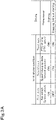
- Fig. 3A and Fig. 3B show examples of the driving conditions.
- Fig. 3A shows the driving conditions (first driving conditions) for starting the prime mover 4.
- Parameters of the first driving conditions include a first state indicating a switching state of the ignition switch 41, a second state indicating a speed-changing state of the speed-changing device 5, and a third state indicating a driving state of the PTO driving unit 5e.
- the first control unit 40A when the first, second and third states are all in on-states, the first control unit 40A outputs a driving start signal to the prime mover 4 to start the prime mover 4. In addition, when the first state is in an off-state, the second and third states are in the on-states, the first control unit 40A does not output the driving start signal to the prime mover 4 and does not start the prime mover 4. Or, when the first state is in the on-state and the second and third states are in the off-states, the first control unit 40A does not output the driving start signal to the prime mover 4 and does not start the prime mover 4.
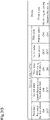
- Fig. 3B shows driving conditions (second driving conditions) for determining, after starting the prime mover 4, whether or not to maintain the driving of the prime mover 4.
- parameters of the second driving condition include a switching state of the seat switch 45 (fourth state) and a switching state of the parking switch 42 (fifth state).
- the first control unit 40A when the first, second, third and fifth states are in the on-states and the fourth state is in the off-state, the first control unit 40A outputs a driving maintaining signal to the prime mover 4 to maintain the driving of the prime mover 4.
- the first control unit 40A When the first, third and fifth states are in the on-states and the second and fourth states are in the off-states, the first control unit 40A outputs a driving stopping signal to the prime mover 4 to stop the driving of the prime mover 4.
- the first control unit 40A In a case where the first and fourth states are in the on-state, the first control unit 40A outputs the driving maintaining signal to the prime mover 4 to maintain the driving of the prime mover 4, regardless of whether the second, third and fifth states are in the on-state or in the off-state.
- the notification device 46 generates the warning when at least the first state is in the on-state and the third and fourth states are in the off-states. That is, the warning is generated in a case where the PTO switch 44 is turned off and the seat switch 45 is turned off even when the ignition switch 41 is turned on.
- the driving conditions are examples and are not limited to those described above.
- the second control unit 40B controls the first indicator light 31 and the second indicator light 32 based on lighting conditions.
- the lighting conditions are conditions for lighting, flashing, and extinguishing the first and second indicator lights 31 and 32.
- the lighting condition data indicating the lighting conditions is stored in the storage unit 47.
- the parameters of the lighting conditions include a switching state of the directional indicator switch 50 (sixth state) and a switching state of the hazard switch 51 (seventh state).
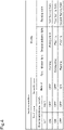
- Fig. 4 shows examples of the lighting conditions. As shown in Fig. 4 , when the sixth state is in a left-on and right-off state and the seventh state is in the off-state, the second control unit 40B flashes the first left indicator 31L and the second left indicator 32L in the first flashing pattern. When the sixth state is in the left-off and right-on state and the seventh state is in the off-state, the second control unit 40B flashes the first right indicator 31R and the second right indicator 32R in the first flashing form.
- the second control unit 40B flashes the first left indicator 31L, the first right indicator 31R, the second left indicator 32L, and the second right indicator 32R in a second flashing pattern.
- the flashing form indicates intervals of the flashing, and the like, and the first flashing pattern, for example, is different from the second flashing pattern in the flashing intervals (time from the lighting to the extinguishing).
- the lighting conditions are examples and are not limited to those described above.
- Fig. 5A there are, in the first driving condition, many combinations of the on-states and the off-states in the first, second and third states (first pattern, second pattern, and so on) when the prime mover 4 is driven, and there are, in the second driving condition, many combinations of the on-states and the off-states in the first, second, third, fourth, and fifth states (eleventh pattern, twelfth pattern, and so on) when the prime mover 4 is driven.
- the first driving condition there are, in the first driving condition, many combinations of the on-states and the off-states in the first, second and third states (twenty-first pattern, twenty-second pattern, and so on) when the prime mover 4 is stopped, and there are, in the second driving condition, many combinations of the on-states and the off-states in the first, second, third, fourth, and fifth states (thirty-first pattern, thirty-second pattern, and so on) when the prime mover 4 is stopped.
- the on-state and off-state in the sixth state there are many combinations of the on-state and off-state in the seventh state, and lighting patterns (fifty-first pattern, fifty-second pattern, and so on) when lighting, flashing, and extinguishing the first indicator light 31 and the second indicator light 32.
- the patterns of driving conditions (first driving condition, second driving condition) and the patterns of the lighting conditions are determined specifically for destinations of the integrated controller 40, that is, regions (first region, second region, third region, fourth region, and so on), and there is the setting data including the combination of driving conditions and lighting conditions which are determined specifically for the region (driving condition data, lighting condition data).
- the setting data for each region is stored in the external terminal 49.
- Destination information indicating the destination (region) is stored in the integrated controller 40.
- the external terminal 49 is connected to the connection section 48.
- the integrated controller 40 writes the setting data to the storage unit 47.
- the setting data B is transferred and written to the storage unit 47 when the integrated controller 40 obtains the setting data B
- the setting data C is not written to the storage unit 47 when the integrated controller 40 obtains the setting data C.
- the integrated controller 40 stores, in the storage unit 47, only the destination information, i.e., the setting data adapted to the destination (region); however, the integrated controller 40 may store, in the storage unit 47, a plural pieces of setting data adapted to a plurality of regions including its own destination. In this case, the integrated controller 40 may change the setting data to another setting data to be used for control by the integrated controller 40 when the region is determined by a switch (region changeover switch) 55 disposed around the driver's seat 10 or the like.
- the region changeover switch 55 is, for example, a rotary switch, and the region can be selected by turning a pick portion thereof.
- the first control unit 40A and the second control unit 40B of the integrated controller 40 usually perform the control using the default setting data B.
- the first control unit 40A and the second control unit 40B of the integrated controller 40 perform the control using the setting data A.
- a display device 57 disposed around the driver's seat 10 displays a plurality of destinations (regions) and a list of driving and lighting conditions adapted to the regions.
- the region changeover switch 55 By operating the region changeover switch 55, the region is changed from the currently-selected region, and the setting data can be switched by operating the display device 57 or the region changeover switch 55 to determine the region.
- the storage unit 47 stores a first disconnection judgment condition for judging disconnection of the first indicator light 31 and a second disconnection judgment condition for judging disconnection of the second indicator light 32.
- the first disconnection judgment condition and the second disconnection judgment condition are different conditions from each other, and there is a difference between the conditions in voltage (current) at which the integrated controller 40 determines the disconnection.
- a voltage (current) V1 for detecting the first disconnection judgment condition is set to be lower than a voltage (current) V2 for detecting the second disconnection judgment condition.
- the second control unit 40B determines the disconnection when a voltage of a line connecting the first indicator light 31 and the integrated controller 40 falls to be equal to or less than the voltage V1, that is, when the first disconnection judgment condition is satisfied. And, the second control unit 40B determines the disconnection when a voltage of a line connecting the second indicator light 32 and the integrated controller 40 falls to be equal to or less than the voltage V2, that is, when the second disconnection judgment condition is satisfied.
- the second control unit 40B detects the disconnection of the first indicator light 31, the second control unit 40B displays a warning indicating that the first indicator light 31 is disconnected (disconnection in lamp, or the like) on the display unit 57 disposed around the driver's seat 10.
- the second control unit 40B When the second control unit 40B detects the disconnection of the second indicator light 32, the second control unit 40B displays a warning indicating that the second indicator light 32 is disconnected (disconnection in lamp, or the like) on the display unit 57. That is, the second control unit 40B is capable of independently notifying of the disconnection of the first indicator light 31 on the tractor 1 side and the disconnection of the second indicator light 32 on the working device 2 side.
- the working vehicle 1 includes the prime mover 4 provided on the vehicle body 3, the first indicator light 31 provided on the vehicle body 3, the second indicator light provided on the working device connected to the vehicle body 3, and the integrated controller 40 including the first control unit 40A to control the prime mover 4, and the second control unit 40B to control the first indicator light 31 and the second indicator light 32.
- the integrated controller 40 since the integrated controller 40 is capable of controlling the prime mover 4 and the indicator lights (first indicator light 31 and second indicator light 32), the settings (conditions) for the prime mover 4 and the indicator lights (first indicator light 31 and second indicator light 32) can be changed at the same time to be easily adapted to the destination.
- the integrated controller 40 includes the storage unit 47 to store the driving condition required for the first control unit 40A to drive the prime mover 4, and the lighting condition required for the second control unit 40B to either light or extinguish each of the first indicator light 31 and the second indicator light 32. According to this configuration, the driving condition for the prime mover 4 and the conditions for the indicator lights (first indicator light 31 and second indicator light 32) can be changed at the same time.
- the working vehicle 1 further includes the connection section 48 configured so that the external terminal 49 for storing setting data including the driving condition and the lighting condition can be connected to the connection section 48.
- the integrated controller 40 is configured or programmed to make the storage unit 47 store the setting data when the setting data is transmitted from the external terminal 49 to the integrated controller 40 via the connection section 48 and when combination of the driving condition and the lighting condition in the transmitted setting data coincides to a predetermined combination of the driving condition and the lighting condition.
- the setting data can be stored (memorized) in the storage unit 47 when the combination of the driving condition and the lighting condition is adapted to the destination.
- the working vehicle 1 further includes the ignition switch 41 configured to perform starting of the prime mover 4, the speed-changing device 5 configured to perform speed-changing of the vehicle body 3 in traveling, and the PTO driving device 5e configured to be driven by power from the prime mover 4 and transmit a driving force thereof to the working device 2.
- the first control unit 40A is configured or programmed to drive the prime mover 4 when a switching state of the ignition switch 41, a speed-changing state of the speed-changing device 5 and a driving state of the PTO driving device 5e coincide to those defined as the driving condition. According to this configuration, the working device 2 is capable of performing work under various conditions.
- the working vehicle 1 further includes the directional indicator switch 50 operable to flash the first and second indicator lights 31 and 32 for direction indication, and the hazard switch 51 operable to flash the first and second indicator lights 31 and 32 for hazard indication.
- the second control unit 40B is configured or programmed to flash each of the first and second indicator lights 31 and 32 when an operation state of the directional indicator switch 50 and an operation state of the hazard switch 51 coincide to those defined as the driving condition. According to this configuration, when the driving conditions for direction indication and hazard indication are the driving conditions adapted to the destination, the direction indication and the hazard indication can be flashed according to specifications for the destination.
- the storage unit 47 previously stores the first disconnection judgment condition required to determine the first indicator light 31 as being disconnected and a second disconnection judgment condition required to determine the second indicator light 32 as being disconnected.
- the second control unit 40B is configured or programmed to determine the first indicator light 31 as being disconnected when the first indicator light 31 is found as being in the first disconnection judgment condition, and to determine the second indicator light 32 as being disconnected when the second indicator light 32 is found as being in the second disconnection judgment condition. According to this configuration, disconnection of the first indicator light 31 on the working vehicle 1 side and disconnection of the second indicator light 32 on the working device 2 side can be judged separately.
- the integrated controller 40 includes a single casing. According to this configuration, compared with a case where a unit for controlling the prime mover 4 and a unit for controlling the first and second indicator lights 31 and 32 are separately configured, the integrated controller 40 can not only be made compact but can also be easily adapted to the destination.
Landscapes
- Engineering & Computer Science (AREA)
- Mechanical Engineering (AREA)
- Chemical & Material Sciences (AREA)
- Combustion & Propulsion (AREA)
- Transportation (AREA)
- Automation & Control Theory (AREA)
- Human Computer Interaction (AREA)
- Lighting Device Outwards From Vehicle And Optical Signal (AREA)
Abstract
Description
- The present invention relates to a working vehicle.
- A technique disclosed in
Patent Document 1 is known, which is a technique for displaying an indicator light in a working machine such as a tractor. The working machine ofPatent Document 1 includes a signal generating unit configured to generate a flash signal for at least flashing a pair of indicator lights, and a priority setting unit configured to prioritize either a flashing action of the indicator lights based on an operation of a directional instruction tool or another flashing action of the indicator lights based on an operation of a hazard instruction tool. And, a switching unit configured to turns on or off the pair of indicator lights based on a control signal from the priority setting unit is connected to the signal generating unit and the pair of indicator lights therebetween. - [Patent document 1]
Japanese Unexamined Patent Publication No. 2015-189358 - In
Patent Document 1, either a setting for hazard priority or another setting for directional indicator priority can be adopted according to a destination for export. Either the setting for hazard priority or the other setting for directional indicator priority can be adopted according to a destination for export inPatent Document 1; however, if specifications for the destination are changed or if specifications other than that of the indicator lights are differed according to destinations for export, it causes a problem that various modifications have to be made, such as changing of connections between harnesses or setting of conditions. - In view of the above-described problems, the present invention intends to provide a working vehicle capable of being easily adapted to a destination for export.
- Technical means of the invention to solve this technical problems are characterized by the following points.
- A working vehicle, includes a prime mover provided on a vehicle body, a first indicator light provided on the vehicle body, a second indicator light provided on a working device connected to the vehicle body, and an integrated controller including a first control unit to control the prime mover, and a second control unit to control the first indicator light and the second indicator light.
- The integrated controller includes a storage unit to store a driving condition required for the first control unit to drive the prime mover, and a lighting condition required for the second control unit to either light or extinguish each of the first indicator light and the second indicator light.
- The working vehicle, further includes a connection section configured so that an external terminal for storing setting data including the driving condition and the lighting condition can be connected to the connection section. The integrated controller is configured or programmed to make the storage unit store the setting data when the setting data is transmitted from the external terminal to the integrated controller via the connection section and when combination of the driving condition and the lighting condition in the transmitted setting data coincides to a predetermined combination of the driving condition and the lighting condition.
- The working vehicle, further includes an ignition switch configured to perform starting of the prime mover, a speed-changing device configured to perform speed-changing of the vehicle body in traveling, and a PTO driving device configured to be driven by power from the prime mover and transmit a driving force thereof to the working device. The first control unit is configured or programmed to drive the prime mover when a switching state of the ignition switch, a speed-changing state of the speed-changing device and a driving state of the PTO driving device coincide to those defined as the driving condition.
- The working vehicle, further includes a directional indicator switch operable to flash the first and second indicator lights for direction indication, and a hazard switch operable to flash the first and second indicator lights for hazard indication. The second control unit is configured or programmed to flash each of the first and second indicator lights when an operation state of the directional indicator switch and an operation state of the hazard switch coincide to those defined as the driving condition.
- The storage unit previously stores a first disconnection judgment condition required to determine the first indicator light as being disconnected and a second disconnection judgment condition required to determine the second indicator light as being disconnected. The second control unit is configured or programmed to determine the first indicator light as being disconnected when the first indicator light is found as being in the first disconnection judgment condition, and to determine the second indicator light as being disconnected when the second indicator light is found as being in the second disconnection judgment condition.
- The integrated controller includes a single casing.
- According to the present invention, it is possible to be easily modified according to a destination for export.
-
- Fig. 1
- is a schematic view of a whole of a speed-changing device.
- Fig. 2
- is a control block diagram of a tractor.
- Fig. 3A
- is a view showing an example of a first driving condition.
- Fig. 3B
- is a view showing an example of a second driving condition.
- Fig. 4
- is a view showing an example of a lighting condition.
- Fig. 5A
- is a view showing an example of a combination of the first driving condition and the lighting condition.
- Fig. 5B
- is a view showing a relationship between setting data and a combination of the driving condition and the lighting condition.
- Fig. 6
- is a plan view of a tractor.
- Fig. 7
- is a side view of the tractor.
- Referring to drawings, an embodiment of the present invention will be described below.
-
Fig. 7 shows a side view of a workingvehicle 1 according to an embodiment, andFig. 7 shows a plan view of the workingvehicle 1 according to the embodiment. In the embodiment, theworking vehicle 1 is a tractor. However, the workingvehicle 1 is not limited to the tractor, and may be an agricultural machine (agricultural vehicle) such as a combine harvester or a transplanter. - Hereinafter, a forward direction from a driver sitting on a driver's
seat 10 of the tractor (working vehicle) 1 is described as the front, a backward direction from the driver is described as the rear, a leftward direction from the driver is described as the left, and a rightward direction from the driver is described as the right. In addition, a horizontal direction, which is a direction orthogonal to a fore-and-aft direction of theworking vehicle 1, is described as a width direction in a vehicle body. - As shown in
Fig. 7 , thetractor 1 includes avehicle body 3 having atraveling device 7, aprime mover 4, and a speed-changingdevice 5. Thetraveling device 7 is a device havingfront wheels 7F andrear wheels 7R. Thefront wheels 7F may be tire types or crawler types. In addition, the rear wheels R7 may be tire types or crawler types. Theprime mover 4 is an internal combustion engine such as a gasoline engine or diesel engine, an electric motor, or the like. In this embodiment, theprime mover 4 is a diesel engine. - The speed-changing
device 5 is capable of changing a speed of rotary force for propelling thetraveling device 7, and is capable of switching the traveling direction of thetraveling device 7 to forward or backward. Acabin 9 is provided on thevehicle body 3, and a driver'sseat 10 is provided in thecabin 9. - In addition, a
lifting device 8 is disposed at a rear portion of thevehicle body 3. The workingdevice 2 can be attached to and detached from thelifting device 8. In addition, thelifting device 8 can raise and lower the workingdevice 2 attached thereto. The workingdevice 2 is a cultivating device for cultivation, a fertilizer spreading device for spreading fertilizer, a pesticide spreading device for spreading pesticide, a harvester for harvesting, a mowing device for mowing grass or the like, a spreading device for spreading the grass or the like, a raking device for raking the grass or the like, a baling device for baling the grass or the like, a trailer for transporting, or the like. - As shown in
Fig. 6 , thevehicle body 3 of thetractor 1 has afirst indicator light 31. Thefirst indicator light 31 is a lamp configured to light, be extinguished, and flash. Thefirst indicator light 31 includes a first left indicator light 31L disposed on a left portion of thevehicle body 3 and a firstright indicator light 31R disposed on a right portion of thevehicle body 3. In addition, asecond indicator light 32 is provided on the workingdevice 2. Thesecond indicator light 32 is a lamp configured to light, be extinguished, and flash. Thesecond indicator light 32 includes a second left indicator light 32L disposed on a left portion of the workingdevice 2 and a secondright indicator light 32R disposed on a right portion of the workingdevice 2. - As shown in
Fig. 1 , the speed-changingdevice 5 includes a main shaft (propulsion shaft) 5a, ashuttle unit 5b, a main speed-changingunit 5c, a sub speed-changingunit 5d, a PTOpower transmission unit 5e, and a front speed-changingunit 5f. Thepropulsion shaft 5a is rotatably supported by a housing case of the speed-changingdevice 5, and a power from the crankshaft of theprime mover 4 is transmitted to thepropulsion shaft 5a. - The
shuttle unit 5b includes a shuttle shaft 5b1 and a forward /backward-traveling switching unit 5b2. A power from thepropulsion shaft 5a is transmitted to the shuttle shaft 5b1. The forward/backward-traveling switching unit 5b2 is constituted of, for example, a hydraulic clutch or the like, and is configured to switch, through engagement and disengagement of the hydraulic clutch, a rotational direction of the shuttle shaft 5b1, i.e., a traveling direction of thetractor 1 between the forward traveling and the backward traveling. - The main speed-changing
unit 5c is a continuously variable speed-changing mechanism that changes the input power in a stepless manner. The continuously variable speed-changing mechanism includes a hydraulic pump 5c1, a hydraulic motor 5c2, and a planetary gear mechanism 5c3. The hydraulic pump 5c1 is rotated by a power from an output shaft 5b3 of theshuttle unit 5b. The hydraulic pump 5c1 is, for example, a variable displacement pump including aswash plate 12, and is configured to change an angle of the swash plate 12 (swash plate angle) to change a flow rate of hydraulic fluid delivered from the hydraulic pump 5c1. The hydraulic motor 5c2 is a motor configured to be rotated by the hydraulic fluid delivered from the hydraulic pump 5c1 through a hydraulic circuit such as piping. A rotation speed of the hydraulic motor 5c2 can be changed by changing the swash plate angle of the hydraulic pump 5c1 or by changing a power to be input to the hydraulic pump 5c1. - The planetary gear mechanism 5c3 is a mechanism that includes a plurality of gears (toothed wheels) and power transmission shafts including an input shaft and an output shaft, and includes an
input shaft 13 to which a power of the hydraulic pump 5c1 is input, aninput shaft 14 to which a power of the hydraulic motor 5c2 is input, and anoutput shaft 15 from which the power is output. The planetary gear mechanism 5c3 combines the powers of the hydraulic pump 5c1 and the hydraulic motor 5c2 and then transmits the combined power to theoutput shaft 15. - In this manner, according to the main speed-changing
unit 5c, the power to be output to the sub speed-changingunit 5d can be changed by changing the swash plate angle of theswash plate 12 of the hydraulic pump 5c1, a rotation speed of theprime mover 4, and the like. The main speed-changingunit 5c is a continuously variable speed-changing mechanism. Alternatively, the main speed-changingunit 5c may be a stepped speed-changing mechanism including gears to change the speed. - The sub speed-changing
unit 5d is a speed-changing mechanism including a plurality of stepped-speed gears (toothed wheels) for speed-shifting the transmitted power, and selects appropriate gears to be drivingly connected (engaged) among the plurality of gears to change (that is, speed-change) the power input from theoutput shaft 15 of the planetary gear mechanism 5c3 and output the speed-changed power to the sub speed-changingunit 5d. The sub speed-changingunit 5d includes an input shaft 5d1, a first speed-changing clutch 5d2, a second speed-changing clutch 5d3, and an output shaft 5d4. The input shaft 5d1 is a shaft to which the power of theoutput shaft 15 of the planetary gear mechanism 5c3 is input, and inputs the input power to the first speed-changing clutch 5d2 and the second speed-changing clutch 5d3 through the gears or the like. By selectively engaging or disengaging each of the first speed-changing clutch 5d2 and the second speed-changing clutch 5d3, the input power is speed-changed and output to the output shaft 5d4. The power output to the output shaft 5d4 is transmitted to a rear-wheel differential device 20R. The rear-wheel differential device 20R rotatably supportsrear axles 21R to which therear wheels 7R are attached. - The PTO power transmission unit (PTO driving unit) 5e includes a PTO clutch 5e1, a PTO propulsion shaft 5e2, and a PTO speed-changing unit 5e3. The PTO clutch 5e1 is, for example, constituted of a hydraulic clutch or the like, and is shifted, through engagement and disengagement of the hydraulic clutch, between a state (engaged state) in which the power of the
propulsion shaft 5a is transmitted to the PTO propulsion shaft 5e2 and a state (disengaged state) in which the power of thepropulsion shaft 5a is not transmitted to the PTO propulsion shaft 5e2. The PTO speed-changing unit 5e3 includes a speed-changing clutch, a plurality of gears, and the like, and speed-changes the power (rotation speed) input from the PTO propulsion shaft 5e2 outputs the speed-changed power to the PTO speed-changing unit 5e3. The power of the PTO transmission 5e3 is transmitted to thePTO shaft 16 through gears and the like. - The front speed-changing
unit 5f includes a first front speed-changing clutch 5f1 and a second front speed-changing clutch 5f2. The first front speed-changing clutch 5f1 and the second front speed-changing clutch 5f2 are capable of transmitting the power from the sub speed-changingunit 5d, and the power of the output shaft 5d4 is transmitted through gears and a transmission shaft, for example. The powers from the first front speed-changing clutch 5f1 and the second front speed-changing clutch 5f2 can be transmitted tofront axles 21F via a front transmission shaft 22. Specifically, the front transmission shaft 22 is connected to the front wheeldifferential device 20F, and the front wheeldifferential device 20F rotatably supports thefront axles 21F to which thefront wheels 7F are attached. - Each of the first front speed-changing clutch 5f1 and the second front speed-changing clutch 5f2 is constituted of a hydraulic clutch or the like. A fluid passage is connected to the first front speed-changing clutch 5f1, and the fluid passage is connected to a control valve to which hydraulic fluid delivered from the hydraulic pump is supplied. The first front speed-changing clutch 5f1 is shifted between the engaged state and the disengaged state according to an opening degree of the control valve. A fluid passage is connected to the second front speed-changing clutch 5f2, and the fluid passage is connected to a control valve. The second front speed-changing clutch 5f2 is shifted between the engaged state and the disengaged state according to an opening degree of the control valve. Each of the control valves is, for example, a two-position switching valve with a solenoid valve, which is shifted to the engaged state or disengaged state when magnetizing or demagnetizing each of solenoids of the solenoid valves.
- When the first front speed-changing clutch 5f1 is in the disengaged state and the second front speed-changing clutch 5f2 is in the engaged state, the power of the sub speed-changing
unit 5d is transmitted to thefront wheels 7F through the second front speed-changing clutch 5f2. This results in four-wheel driving (4WD) in which the front and rear wheels are driven by the power and the rotational speeds of the front and rear wheels are approximately the same (constant speed 4WD state). On the other hand, when the first front speed-changing clutch 5f1 is in the engaged state and the second front speed-changing clutch 5f2 is in the disengaged state, the four-wheel driving is performed and the rotation speeds of the front wheels becomes faster than the rotation speeds of the rear wheels (accelerated 4WD state). In addition, when the first front speed-changing clutch 5f1 and the second front speed-changing clutch 5f2 are in the engaged state, two-wheel driving (2WD) in which the rear wheels are driven by power is performed because the power of the sub speed-changingunit 5d is not transmitted to thefront wheels 7F. - As shown in
Fig. 2 , thetractor 1 includes anintegrated controller 40. Theintegrated controller 40 is a unit integrating a control unit that controls theprime mover 4 and a control unit that controls thefirst indicator light 31 and thesecond indicator light 32, and includes a single casing incorporating these components. Theintegrated controller 40 is constituted of a CPU, an electric/electronic circuit, and the like, and stores predetermined computer programs. - An
ignition switch 41, aparking switch 42, a speed-changingswitch 43, aPTO switch 44, aseat switch 45, and anotification device 46 are connected to theintegrated controller 40. Theignition switch 41, theparking switch 42, the speed-changingswitch 43, and thePTO switch 44 are switches that can be operated by a driver. - The
ignition switch 41 is operable at least to be turned on or off, Theignition switch 41 is turned on when theprime mover 4 is to be driven, and is turned off when the driving of theprime mover 4 is to be stopped. Theparking switch 42 is a switch configured to detect parking of the traveling vehicle body (vehicle body) 3. Specifically, theparking switch 42 is operable to be turned on or off. When a parking lever (parking brake), which is swingably supported by thevehicle body 3, is shifted to a position (braking position) for braking thevehicle body 3, theparking switch 42 is turned on according to swinging of the parking lever to detect the parking. When the parking lever is shifted to a position (releasing position) for releasing the braking of thevehicle body 3, theparking switch 42 is turned off according to swinging of the parking lever and does not detect the parking. - The speed-changing
switch 43 is a switch capable of detecting at least a neutral state (neutral position). In this regard, the speed-changingswitch 43 is turned on when the speed-changing lever is in the neutral position, and is turned off when the speed-changing lever is in a position other than the neutral position. - The PTO switch 44 is operable to be turned on or off to selectively allow or disable the driving of the
PTO shaft 16. For example, when thePTO switch 44 is turned on, the driving of thePTO shaft 16 is in an "allowed state", and when thePTO switch 44 is turned off, the driving of thePTO shaft 16 is in a "disabled state". When thePTO switch 44 is turned on, the PTO clutch 5e1 enters the engaged state, and thePTO shaft 16 is driven (rotated). On the other hand, when thePTO switch 44 is turned off, the PTO clutch 5e1 enters the disengaged state, and the driving (rotation) of thePTO shaft 16 stops. - The
seat switch 45 is a switch configured to detect that a driver is sitting on the driver'sseat 10. For example, theseat switch 45 is operable to be turned on or off. Theseat switch 45 is disposed in a portion (seating portion, backrest) of the driver's seat 6, or below the seat or the like. When the driver sits on the seat to contact the portion, theseat switch 45 is turned on to detect the seating. In addition, when the driver leaves the seat to be separated from the portion, theseat switch 45 is turned off to detect that the driver is not sitting on the seat. - The
notification device 46 is a monitor on which various information can be displayed, a light source lamp such as an LED, a speaker that generates a warning sound, or the like. Only when a predetermined condition is satisfied, thenotification device 46 issues a warning to be displayed on the monitor, a warning as lighting and flashing the light source lamp, or a warning as generating a warning sound. - In addition, a
directional indicator switch 50 and thehazard switch 51 are connected to theintegrated controller 40. Thedirectional indicator switch 50 and thehazard switch 51 are switches that can be operated by the driver. Thedirectional indicator switch 50 is a switch configured to be shifted in accordance with the indicator lever that is operated to indicate a traveling direction of thevehicle body 3. In a case where the indicator lever is in the neutral state (a case of not indicating the traveling direction), thedirectional indicator switch 50 is in theneutral position 50a. Thedirectional indicator switch 50 is shifted to aleft instructing position 50b when the indicator lever is on one directional side for leftward direction indication, and is shifted to aright instructing position 50c when the indicator lever is on the other directional side for rightward direction indication. Hereafter, for convenience of explanation, the state where thedirectional indicator switch 50 is in theneutral position 50a may be referred to as an "off-state", the state where thedirectional indicator switch 50 is in theleft instructing position 50b may be referred to as a "left-on and right-off state", and the state where thedirectional indicator switch 50 is in theright instructing position 50c may be referred to as a "left-off and right-on state". - The
hazard switch 51 is a switch configured to be shifted in accordance with a hazard operating tool that instructs to notify the hazard. Thehazard switch 51 is turned on when the hazard operating tool is shifted to one directional side for notifying of the hazard, and is turned off when the hazard operating tool is shifted to the other directional side for not notifying of the hazard. - In addition, a
connection section 48 is provided in theintegrated controller 40. Theconnection section 48 is a connector or the like to which a cable for transmitting data and the like is connected. Anexternal terminal 49 can be connected to theconnection section 48. Theexternal terminal 49 may be a terminal device certified by a manufacturer of thetractor 1, a sales dealer who sells thetractor 1 or a maintenance store who maintains thetractor 1, or a control unit of the tractor, or the like. In a case where the control unit of the tractor is connected as theexternal terminal 49, theconnection section 48 can be configured to allow the CAN communication. Theexternal terminal 49 is a terminal capable of transmitting data such as computer programs, parameters and the like to theintegrated controller 40. In a case where theexternal terminal 49 is connected to theconnection section 48 of theintegrated controller 40, the data output from theexternal terminal 49 is written to theintegrated controller 40 when the certification is performed between theintegrated controller 40 and theexternal terminal 49 and the certification is established. Note that it is possible to omit the certification with theexternal terminal 49 at a stage of manufacturing the integratedcontroller 40. - The
integrated controller 40 includes afirst control unit 40A, asecond control unit 40B, and astorage unit 47. Each of thefirst control unit 40A and thesecond control unit 40B is constituted of an electric/electronic circuit provided in theintegrated controller 40, a computer program stored in theintegrated controller 40, or the like. Thestorage unit 47 is constituted of a nonvolatile memory or the like. - The
first control unit 40A controls theprime mover 4 based on a driving condition. The driving condition is a condition for determining whether or not to drive theprime mover 4. Driving condition data indicating the driving condition is stored in thestorage unit 47. -
Fig. 3A andFig. 3B show examples of the driving conditions.Fig. 3A shows the driving conditions (first driving conditions) for starting theprime mover 4. Parameters of the first driving conditions include a first state indicating a switching state of theignition switch 41, a second state indicating a speed-changing state of the speed-changingdevice 5, and a third state indicating a driving state of thePTO driving unit 5e. - As shown in
Fig. 3A , for example, when the first, second and third states are all in on-states, thefirst control unit 40A outputs a driving start signal to theprime mover 4 to start theprime mover 4. In addition, when the first state is in an off-state, the second and third states are in the on-states, thefirst control unit 40A does not output the driving start signal to theprime mover 4 and does not start theprime mover 4. Or, when the first state is in the on-state and the second and third states are in the off-states, thefirst control unit 40A does not output the driving start signal to theprime mover 4 and does not start theprime mover 4. -
Fig. 3B shows driving conditions (second driving conditions) for determining, after starting theprime mover 4, whether or not to maintain the driving of theprime mover 4. In addition to the first, second and third states, parameters of the second driving condition include a switching state of the seat switch 45 (fourth state) and a switching state of the parking switch 42 (fifth state). - As shown in
Fig. 3B , when the first, second, third and fifth states are in the on-states and the fourth state is in the off-state, thefirst control unit 40A outputs a driving maintaining signal to theprime mover 4 to maintain the driving of theprime mover 4. When the first, third and fifth states are in the on-states and the second and fourth states are in the off-states, thefirst control unit 40A outputs a driving stopping signal to theprime mover 4 to stop the driving of theprime mover 4. In a case where the first and fourth states are in the on-state, thefirst control unit 40A outputs the driving maintaining signal to theprime mover 4 to maintain the driving of theprime mover 4, regardless of whether the second, third and fifth states are in the on-state or in the off-state. - The
notification device 46 generates the warning when at least the first state is in the on-state and the third and fourth states are in the off-states. That is, the warning is generated in a case where thePTO switch 44 is turned off and theseat switch 45 is turned off even when theignition switch 41 is turned on. The driving conditions (first driving condition and second driving condition) are examples and are not limited to those described above. - The
second control unit 40B controls thefirst indicator light 31 and thesecond indicator light 32 based on lighting conditions. The lighting conditions are conditions for lighting, flashing, and extinguishing the first and second indicator lights 31 and 32. The lighting condition data indicating the lighting conditions is stored in thestorage unit 47. - The parameters of the lighting conditions include a switching state of the directional indicator switch 50 (sixth state) and a switching state of the hazard switch 51 (seventh state).
Fig. 4 shows examples of the lighting conditions. As shown inFig. 4 , when the sixth state is in a left-on and right-off state and the seventh state is in the off-state, thesecond control unit 40B flashes the firstleft indicator 31L and the secondleft indicator 32L in the first flashing pattern. When the sixth state is in the left-off and right-on state and the seventh state is in the off-state, thesecond control unit 40B flashes the firstright indicator 31R and the secondright indicator 32R in the first flashing form. When the sixth state is in the off-state and the seventh state is in the on-state, thesecond control unit 40B flashes the firstleft indicator 31L, the firstright indicator 31R, the secondleft indicator 32L, and the secondright indicator 32R in a second flashing pattern. The flashing form indicates intervals of the flashing, and the like, and the first flashing pattern, for example, is different from the second flashing pattern in the flashing intervals (time from the lighting to the extinguishing). The lighting conditions are examples and are not limited to those described above. - As shown in
Fig. 5A , there are, in the first driving condition, many combinations of the on-states and the off-states in the first, second and third states (first pattern, second pattern, and so on) when theprime mover 4 is driven, and there are, in the second driving condition, many combinations of the on-states and the off-states in the first, second, third, fourth, and fifth states (eleventh pattern, twelfth pattern, and so on) when theprime mover 4 is driven. - There are, in the first driving condition, many combinations of the on-states and the off-states in the first, second and third states (twenty-first pattern, twenty-second pattern, and so on) when the
prime mover 4 is stopped, and there are, in the second driving condition, many combinations of the on-states and the off-states in the first, second, third, fourth, and fifth states (thirty-first pattern, thirty-second pattern, and so on) when theprime mover 4 is stopped. - In the lighting conditions, there are many combinations of the on-state and off-state in the sixth state, the on-state and off-state in the seventh state, and lighting patterns (fifty-first pattern, fifty-second pattern, and so on) when lighting, flashing, and extinguishing the
first indicator light 31 and thesecond indicator light 32. - As shown in
Fig. 5B , the patterns of driving conditions (first driving condition, second driving condition) and the patterns of the lighting conditions are determined specifically for destinations of theintegrated controller 40, that is, regions (first region, second region, third region, fourth region, and so on), and there is the setting data including the combination of driving conditions and lighting conditions which are determined specifically for the region (driving condition data, lighting condition data). The setting data for each region is stored in theexternal terminal 49. - Destination information indicating the destination (region) is stored in the
integrated controller 40. During manufacturing or maintenance of theintegrated controller 40, theexternal terminal 49 is connected to theconnection section 48. In a case where the combination of the driving conditions and the lighting conditions coincides to a predetermined combination when the setting data is sent from theexternal terminal 49, theintegrated controller 40 writes the setting data to thestorage unit 47. For example, in a case where the destination of theintegrated controller 40 is the second region, the setting data B is transferred and written to thestorage unit 47 when theintegrated controller 40 obtains the setting data B, and the setting data C is not written to thestorage unit 47 when theintegrated controller 40 obtains the setting data C. - In the above-described embodiment, the
integrated controller 40 stores, in thestorage unit 47, only the destination information, i.e., the setting data adapted to the destination (region); however, theintegrated controller 40 may store, in thestorage unit 47, a plural pieces of setting data adapted to a plurality of regions including its own destination. In this case, theintegrated controller 40 may change the setting data to another setting data to be used for control by theintegrated controller 40 when the region is determined by a switch (region changeover switch) 55 disposed around the driver'sseat 10 or the like. Theregion changeover switch 55 is, for example, a rotary switch, and the region can be selected by turning a pick portion thereof. - In the
integrated controller 40, for example, in a case where the second region is the destination thereof, thefirst control unit 40A and thesecond control unit 40B of theintegrated controller 40 usually perform the control using the default setting data B. When the first region is determined as the region by theregion changeover switch 55, thefirst control unit 40A and thesecond control unit 40B of theintegrated controller 40 perform the control using the setting data A. For example, adisplay device 57 disposed around the driver'sseat 10 displays a plurality of destinations (regions) and a list of driving and lighting conditions adapted to the regions. By operating theregion changeover switch 55, the region is changed from the currently-selected region, and the setting data can be switched by operating thedisplay device 57 or theregion changeover switch 55 to determine the region. - The
storage unit 47 stores a first disconnection judgment condition for judging disconnection of thefirst indicator light 31 and a second disconnection judgment condition for judging disconnection of thesecond indicator light 32. The first disconnection judgment condition and the second disconnection judgment condition are different conditions from each other, and there is a difference between the conditions in voltage (current) at which the integratedcontroller 40 determines the disconnection. For example, in a case where a wattage required to light or flash thefirst indicator light 31 is represented by "W1" and a wattage required to light or flash thesecond indicator light 32 is represented by "W2", W2 is higher than W1, a voltage (current) V1 for detecting the first disconnection judgment condition is set to be lower than a voltage (current) V2 for detecting the second disconnection judgment condition. Thesecond control unit 40B determines the disconnection when a voltage of a line connecting thefirst indicator light 31 and theintegrated controller 40 falls to be equal to or less than the voltage V1, that is, when the first disconnection judgment condition is satisfied. And, thesecond control unit 40B determines the disconnection when a voltage of a line connecting thesecond indicator light 32 and theintegrated controller 40 falls to be equal to or less than the voltage V2, that is, when the second disconnection judgment condition is satisfied. When thesecond control unit 40B detects the disconnection of thefirst indicator light 31, thesecond control unit 40B displays a warning indicating that thefirst indicator light 31 is disconnected (disconnection in lamp, or the like) on thedisplay unit 57 disposed around the driver'sseat 10. When thesecond control unit 40B detects the disconnection of thesecond indicator light 32, thesecond control unit 40B displays a warning indicating that thesecond indicator light 32 is disconnected (disconnection in lamp, or the like) on thedisplay unit 57. That is, thesecond control unit 40B is capable of independently notifying of the disconnection of thefirst indicator light 31 on thetractor 1 side and the disconnection of thesecond indicator light 32 on the workingdevice 2 side. - The working
vehicle 1 includes theprime mover 4 provided on thevehicle body 3, thefirst indicator light 31 provided on thevehicle body 3, the second indicator light provided on the working device connected to thevehicle body 3, and theintegrated controller 40 including thefirst control unit 40A to control theprime mover 4, and thesecond control unit 40B to control thefirst indicator light 31 and thesecond indicator light 32. According to this configuration, since theintegrated controller 40 is capable of controlling theprime mover 4 and the indicator lights (first indicator light 31 and second indicator light 32), the settings (conditions) for theprime mover 4 and the indicator lights (first indicator light 31 and second indicator light 32) can be changed at the same time to be easily adapted to the destination. - The
integrated controller 40 includes thestorage unit 47 to store the driving condition required for thefirst control unit 40A to drive theprime mover 4, and the lighting condition required for thesecond control unit 40B to either light or extinguish each of thefirst indicator light 31 and thesecond indicator light 32. According to this configuration, the driving condition for theprime mover 4 and the conditions for the indicator lights (first indicator light 31 and second indicator light 32) can be changed at the same time. - The working
vehicle 1 further includes theconnection section 48 configured so that theexternal terminal 49 for storing setting data including the driving condition and the lighting condition can be connected to theconnection section 48. Theintegrated controller 40 is configured or programmed to make thestorage unit 47 store the setting data when the setting data is transmitted from theexternal terminal 49 to theintegrated controller 40 via theconnection section 48 and when combination of the driving condition and the lighting condition in the transmitted setting data coincides to a predetermined combination of the driving condition and the lighting condition. According to this configuration, the setting data can be stored (memorized) in thestorage unit 47 when the combination of the driving condition and the lighting condition is adapted to the destination. - The working
vehicle 1 further includes theignition switch 41 configured to perform starting of theprime mover 4, the speed-changingdevice 5 configured to perform speed-changing of thevehicle body 3 in traveling, and thePTO driving device 5e configured to be driven by power from theprime mover 4 and transmit a driving force thereof to the workingdevice 2. Thefirst control unit 40A is configured or programmed to drive theprime mover 4 when a switching state of theignition switch 41, a speed-changing state of the speed-changingdevice 5 and a driving state of thePTO driving device 5e coincide to those defined as the driving condition. According to this configuration, the workingdevice 2 is capable of performing work under various conditions. - The working
vehicle 1 further includes thedirectional indicator switch 50 operable to flash the first and second indicator lights 31 and 32 for direction indication, and thehazard switch 51 operable to flash the first and second indicator lights 31 and 32 for hazard indication. Thesecond control unit 40B is configured or programmed to flash each of the first and second indicator lights 31 and 32 when an operation state of thedirectional indicator switch 50 and an operation state of thehazard switch 51 coincide to those defined as the driving condition. According to this configuration, when the driving conditions for direction indication and hazard indication are the driving conditions adapted to the destination, the direction indication and the hazard indication can be flashed according to specifications for the destination. - The
storage unit 47 previously stores the first disconnection judgment condition required to determine thefirst indicator light 31 as being disconnected and a second disconnection judgment condition required to determine thesecond indicator light 32 as being disconnected. Thesecond control unit 40B is configured or programmed to determine thefirst indicator light 31 as being disconnected when thefirst indicator light 31 is found as being in the first disconnection judgment condition, and to determine thesecond indicator light 32 as being disconnected when thesecond indicator light 32 is found as being in the second disconnection judgment condition. According to this configuration, disconnection of thefirst indicator light 31 on the workingvehicle 1 side and disconnection of thesecond indicator light 32 on the workingdevice 2 side can be judged separately. - The
integrated controller 40 includes a single casing. According to this configuration, compared with a case where a unit for controlling theprime mover 4 and a unit for controlling the first and second indicator lights 31 and 32 are separately configured, theintegrated controller 40 can not only be made compact but can also be easily adapted to the destination. - In the above description, the embodiment of the present invention has been explained. However, all the features of the embodiment disclosed in this application should be considered just as examples, and the embodiment does not restrict the present invention accordingly. A scope of the present invention is shown not in the above-described embodiment but in claims, and is intended to include all modifications within and equivalent to a scope of the claims.
- All combinations of the configurations described in the first to fourth embodiments can be adopted to the invention.
-
- 1
- Working vehicle
- 2
- Working device
- 3
- Vehicle body
- 4
- Prime mover
- 5
- Speed-changing device
- 5e
- PTO driving device
- 31
- First indicator light
- 32
- Second indicator light
- 40
- Integrated controller
- 40A
- First control unit
- 40B
- Second control unit
- 41
- Ignition switch
- 47
- Storage unit
- 48
- Connection section
- 49
- External terminal
- 50
- Directional indicator switch
- 51
- Hazard switch
Claims (7)
- A working vehicle, comprising:- a vehicle body;- a prime mover provided on the vehicle body;- a first indicator light provided on the vehicle body;- a second indicator light provided on a working device connected to the vehicle body; and- an integrated controller including- a first control unit to control the prime mover, and- a second control unit to control the first indicator light and the second indicator light.
- The working vehicle according to claim 1, wherein the integrated controller includes:- a storage unit to store a driving condition required for the first control unit to drive the prime mover, and a lighting condition required for the second control unit to either light or extinguish each of the first indicator light and the second indicator light.
- The working vehicle according to claim 2, further comprising:- a connection section configured so that an external terminal for storing setting data including the driving condition and the lighting condition can be connected to the connection section,wherein the integrated controller is configured or programmed to make the storage unit store the setting data when the setting data is transmitted from the external terminal to the integrated controller via the connection section and when combination of the driving condition and the lighting condition in the transmitted setting data coincides to a predetermined combination of the driving condition and the lighting condition.
- The working vehicle according to claim 2 or 3, further comprising:- an ignition switch configured to perform starting of the prime mover;- a speed-changing device configured to perform speed-changing of the vehicle body in traveling; and- a PTO driving device configured to be driven by power from the prime mover and transmit a driving force thereof to the working device,wherein the first control unit is configured or programmed to drive the prime mover when a switching state of the ignition switch, a speed-changing state of the speed-changing device and a driving state of the PTO driving device coincide to those defined as the driving condition.
- The working vehicle according to any one of claims 2 to 4, further comprising:- a directional indicator switch operable to flash the first and second indicator lights for direction indication; and- a hazard switch operable to flash the first and second indicator lights for hazard indication,wherein the second control unit is configured or programmed to flash each of the first and second indicator lights when an operation state of the directional indicator switch and an operation state of the hazard switch coincide to those defined as the driving condition.
- The working vehicle according to any one of claims 1 to 4, wherein- the storage unit previously stores a first disconnection judgment condition required to determine the first indicator light as being disconnected and a second disconnection judgment condition required to determine the second indicator light as being disconnected, and- the second control unit is configured or programmed- to determine the first indicator light as being disconnected when the first indicator light is found as being in the first disconnection judgment condition, and- to determine the second indicator light as being disconnected when the second indicator light is found as being in the second disconnection judgment condition.
- The working vehicle according to any one of claims 1 to 6, wherein the integrated controller includes a single casing.
Applications Claiming Priority (2)
| Application Number | Priority Date | Filing Date | Title |
|---|---|---|---|
| JP2019122518A JP7159122B2 (en) | 2019-06-28 | 2019-06-28 | work vehicle |
| PCT/JP2020/024418 WO2020262304A1 (en) | 2019-06-28 | 2020-06-22 | Work vehicle |
Publications (2)
| Publication Number | Publication Date |
|---|---|
| EP3992032A1 true EP3992032A1 (en) | 2022-05-04 |
| EP3992032A4 EP3992032A4 (en) | 2023-07-26 |
Family
ID=74061705
Family Applications (1)
| Application Number | Title | Priority Date | Filing Date |
|---|---|---|---|
| EP20830590.4A Pending EP3992032A4 (en) | 2019-06-28 | 2020-06-22 | COMMERCIAL VEHICLE |
Country Status (5)
| Country | Link |
|---|---|
| US (1) | US12054200B2 (en) |
| EP (1) | EP3992032A4 (en) |
| JP (1) | JP7159122B2 (en) |
| CN (1) | CN113993743B (en) |
| WO (1) | WO2020262304A1 (en) |
Family Cites Families (29)
| Publication number | Priority date | Publication date | Assignee | Title |
|---|---|---|---|---|
| JPH0341070Y2 (en) * | 1985-10-04 | 1991-08-29 | ||
| EP0586203B1 (en) * | 1992-09-03 | 1997-01-02 | Grau Limited | Braking systems |
| JPH07223485A (en) * | 1994-02-15 | 1995-08-22 | Kubota Corp | Winker circuit structure of work vehicle |
| JPH10208194A (en) * | 1997-01-21 | 1998-08-07 | Toyota Motor Corp | Vehicle specification change device |
| US6239696B1 (en) * | 1999-03-30 | 2001-05-29 | New Holland North America, Inc. | Signal light system for agricultural equipment |
| JP4142407B2 (en) * | 2002-11-12 | 2008-09-03 | 矢崎総業株式会社 | Waterproof cover structure of electrical junction box |
| DE202005017151U1 (en) * | 2005-03-15 | 2005-12-29 | Conwys Ag | Control device for trailers and bicycle carriers, has serial data bus for receiving and sending data, status and error messages about safety-relevant electrical or electronic parts of trailer, and display or indicator for showing messages |
| US7777495B2 (en) * | 2005-09-16 | 2010-08-17 | Volvo Lastvagnar Ab | Method and a device for detecting signal lamps in a vehicle |
| US8146052B2 (en) * | 2006-08-22 | 2012-03-27 | Caterpillar Inc. | Method and system for hierarchical hardware mapping for software design |
| JP4915793B2 (en) * | 2006-12-26 | 2012-04-11 | 本田技研工業株式会社 | Motorcycle lighting device |
| DE102007010013A1 (en) * | 2007-03-01 | 2008-09-04 | Siemens Ag | Control device for driver assistance system for vehicle, has input for receiving identification information of country, component for assigning country-specific regulations related to road traffic of respective country |
| DE102008000086B4 (en) * | 2008-01-18 | 2009-10-29 | Aspöck Systems GmbH | Method for failure control of light functions in a motor vehicle electrical system |
| US8106760B2 (en) * | 2008-07-29 | 2012-01-31 | Trixcel, Llp | Turn signals generated during operation of vehicle hazard warning lights |
| JP5522011B2 (en) * | 2010-12-08 | 2014-06-18 | 株式会社デンソー | Vehicle direction indication device |
| DE102012003148A1 (en) * | 2012-02-16 | 2013-08-22 | Alois Pöttinger Maschinenfabrik Gmbh | Agricultural attachment for coupling with a work vehicle |
| US20140083392A1 (en) * | 2012-09-27 | 2014-03-27 | International Engine Intellectual Property Company, Llc | Methods for controlling engine idle speed |
| JP2014133438A (en) * | 2013-01-08 | 2014-07-24 | Yanmar Co Ltd | Work machine |
| US20150203026A1 (en) * | 2014-01-22 | 2015-07-23 | Todd A Schotanus | Position and pathway lighting system for a vehicle or combination of vehicles sides undersides rear or trailing wheels and rear or trailing body portion |
| WO2015025537A1 (en) * | 2014-02-18 | 2015-02-26 | 株式会社小松製作所 | Utility vehicle and display device for utility vehicle |
| JP6344946B2 (en) * | 2014-03-28 | 2018-06-20 | 株式会社クボタ | Work implement indicating device and work implement provided with work implement indicating device |
| JP2016084095A (en) * | 2014-10-28 | 2016-05-19 | ヤンマー株式会社 | Work vehicle |
| JP5968488B1 (en) * | 2015-04-08 | 2016-08-10 | 三菱電機株式会社 | Vehicle control device |
| US20170100975A1 (en) * | 2015-10-13 | 2017-04-13 | Ford Global Technologies, Llc | Automatic Trailer Lighting Control |
| US9995780B2 (en) * | 2015-10-14 | 2018-06-12 | Grote Industries, Inc. | Trailer lighting outage detection circuit |
| JP2017109705A (en) * | 2015-12-18 | 2017-06-22 | 株式会社小松製作所 | Work machine management system, work machine control system, and work machine |
| JP6712906B2 (en) * | 2016-05-31 | 2020-06-24 | 株式会社小松製作所 | Work machine management device, work machine, and work machine management system |
| KR102472090B1 (en) * | 2017-01-20 | 2022-12-01 | 가부시끼 가이샤 구보다 | work car |
| JP7060497B2 (en) * | 2018-12-11 | 2022-04-26 | ヤンマーパワーテクノロジー株式会社 | Agricultural autonomous driving work vehicle |
| US20200298757A1 (en) * | 2019-03-22 | 2020-09-24 | Toyota Motor Engineering & Manufacturing North America, Inc. | Staged troubleshooting and repair of vehicle trailer lighting malfunctions |
-
2019
- 2019-06-28 JP JP2019122518A patent/JP7159122B2/en active Active
-
2020
- 2020-06-22 WO PCT/JP2020/024418 patent/WO2020262304A1/en not_active Ceased
- 2020-06-22 CN CN202080040900.2A patent/CN113993743B/en active Active
- 2020-06-22 EP EP20830590.4A patent/EP3992032A4/en active Pending
-
2021
- 2021-12-09 US US17/546,147 patent/US12054200B2/en active Active
Also Published As
| Publication number | Publication date |
|---|---|
| US12054200B2 (en) | 2024-08-06 |
| WO2020262304A1 (en) | 2020-12-30 |
| US20220097702A1 (en) | 2022-03-31 |
| CN113993743A (en) | 2022-01-28 |
| CN113993743B (en) | 2024-09-24 |
| JP7159122B2 (en) | 2022-10-24 |
| JP2021008192A (en) | 2021-01-28 |
| EP3992032A4 (en) | 2023-07-26 |
Similar Documents
| Publication | Publication Date | Title |
|---|---|---|
| US20220290748A1 (en) | Work vehicle | |
| US11951827B2 (en) | Work vehicle | |
| EP3750739B1 (en) | Working vehicle | |
| EP1595734A1 (en) | Vehicle control system, in particular agricultural vehicle | |
| JP6612187B2 (en) | Drive device for PTO shaft in work machine | |
| EP1380488A2 (en) | Vacuum actuated direction and speed control mechanism | |
| US20220340136A1 (en) | Travel mode switching device for vehicle and display unit of the same | |
| US12054200B2 (en) | Working vehicle | |
| JP2003235330A (en) | Work equipment traveling equipment | |
| JP7547307B2 (en) | Work vehicles | |
| US11268614B2 (en) | Working vehicle | |
| JP7001499B2 (en) | Work vehicle | |
| JP5400347B2 (en) | Combine | |
| JP7225037B2 (en) | work vehicle | |
| JP2002193136A (en) | Traveling device | |
| JP7527861B2 (en) | Work vehicles | |
| JP2021008825A (en) | Work vehicle | |
| JP6184359B2 (en) | Tractor | |
| JP2021024330A (en) | Work vehicle | |
| JP2012130304A (en) | Combine harvester | |
| JP2010081821A (en) | Working vehicle | |
| JP6985959B2 (en) | Work vehicle | |
| JP2002193141A (en) | Traveling device | |
| JP2023101048A (en) | work vehicle | |
| JP2009085308A (en) | Travel transmission for work vehicle |
Legal Events
| Date | Code | Title | Description |
|---|---|---|---|
| STAA | Information on the status of an ep patent application or granted ep patent |
Free format text: STATUS: THE INTERNATIONAL PUBLICATION HAS BEEN MADE |
|
| PUAI | Public reference made under article 153(3) epc to a published international application that has entered the european phase |
Free format text: ORIGINAL CODE: 0009012 |
|
| STAA | Information on the status of an ep patent application or granted ep patent |
Free format text: STATUS: REQUEST FOR EXAMINATION WAS MADE |
|
| 17P | Request for examination filed |
Effective date: 20211208 |
|
| AK | Designated contracting states |
Kind code of ref document: A1 Designated state(s): AL AT BE BG CH CY CZ DE DK EE ES FI FR GB GR HR HU IE IS IT LI LT LU LV MC MK MT NL NO PL PT RO RS SE SI SK SM TR |
|
| DAV | Request for validation of the european patent (deleted) | ||
| DAX | Request for extension of the european patent (deleted) | ||
| REG | Reference to a national code |
Ref country code: DE Ref legal event code: R079 Free format text: PREVIOUS MAIN CLASS: B60Q0001380000 Ipc: B60Q0001300000 |
|
| A4 | Supplementary search report drawn up and despatched |
Effective date: 20230627 |
|
| RIC1 | Information provided on ipc code assigned before grant |
Ipc: B60Q 11/00 20060101ALI20230621BHEP Ipc: B62D 49/00 20060101ALI20230621BHEP Ipc: B60Q 1/46 20060101ALI20230621BHEP Ipc: B60Q 1/38 20060101ALI20230621BHEP Ipc: B60Q 1/30 20060101AFI20230621BHEP |
|
| STAA | Information on the status of an ep patent application or granted ep patent |
Free format text: STATUS: EXAMINATION IS IN PROGRESS |
|
| 17Q | First examination report despatched |
Effective date: 20250411 |