EP3992000A1 - Aufhängung für landwirtschaftliches fahrzeug - Google Patents
Aufhängung für landwirtschaftliches fahrzeug Download PDFInfo
- Publication number
- EP3992000A1 EP3992000A1 EP21201284.3A EP21201284A EP3992000A1 EP 3992000 A1 EP3992000 A1 EP 3992000A1 EP 21201284 A EP21201284 A EP 21201284A EP 3992000 A1 EP3992000 A1 EP 3992000A1
- Authority
- EP
- European Patent Office
- Prior art keywords
- spindle
- suspension
- agricultural vehicle
- travel
- stop body
- Prior art date
- Legal status (The legal status is an assumption and is not a legal conclusion. Google has not performed a legal analysis and makes no representation as to the accuracy of the status listed.)
- Granted
Links
Images


Classifications
-
- B—PERFORMING OPERATIONS; TRANSPORTING
- B60—VEHICLES IN GENERAL
- B60G—VEHICLE SUSPENSION ARRANGEMENTS
- B60G3/00—Resilient suspensions for a single wheel
- B60G3/01—Resilient suspensions for a single wheel the wheel being mounted for sliding movement, e.g. in or on a vertical guide
-
- B—PERFORMING OPERATIONS; TRANSPORTING
- B60—VEHICLES IN GENERAL
- B60G—VEHICLE SUSPENSION ARRANGEMENTS
- B60G11/00—Resilient suspensions characterised by arrangement, location or kind of springs
- B60G11/32—Resilient suspensions characterised by arrangement, location or kind of springs having springs of different kinds
- B60G11/34—Resilient suspensions characterised by arrangement, location or kind of springs having springs of different kinds including leaf springs
- B60G11/46—Resilient suspensions characterised by arrangement, location or kind of springs having springs of different kinds including leaf springs and also fluid springs
- B60G11/465—Resilient suspensions characterised by arrangement, location or kind of springs having springs of different kinds including leaf springs and also fluid springs with a flexible wall
-
- B—PERFORMING OPERATIONS; TRANSPORTING
- B60—VEHICLES IN GENERAL
- B60G—VEHICLE SUSPENSION ARRANGEMENTS
- B60G15/00—Resilient suspensions characterised by arrangement, location or type of combined spring and vibration damper, e.g. telescopic type
- B60G15/02—Resilient suspensions characterised by arrangement, location or type of combined spring and vibration damper, e.g. telescopic type having mechanical spring
-
- B—PERFORMING OPERATIONS; TRANSPORTING
- B62—LAND VEHICLES FOR TRAVELLING OTHERWISE THAN ON RAILS
- B62D—MOTOR VEHICLES; TRAILERS
- B62D49/00—Tractors
- B62D49/06—Tractors adapted for multi-purpose use
- B62D49/0607—Straddle tractors, used for instance above vine stocks, rows of bushes, or the like
-
- B—PERFORMING OPERATIONS; TRANSPORTING
- B60—VEHICLES IN GENERAL
- B60G—VEHICLE SUSPENSION ARRANGEMENTS
- B60G2202/00—Indexing codes relating to the type of spring, damper or actuator
- B60G2202/10—Type of spring
- B60G2202/15—Fluid spring
- B60G2202/152—Pneumatic spring
-
- B—PERFORMING OPERATIONS; TRANSPORTING
- B60—VEHICLES IN GENERAL
- B60G—VEHICLE SUSPENSION ARRANGEMENTS
- B60G2204/00—Indexing codes related to suspensions per se or to auxiliary parts
- B60G2204/40—Auxiliary suspension parts; Adjustment of suspensions
- B60G2204/45—Stops limiting travel
-
- B—PERFORMING OPERATIONS; TRANSPORTING
- B60—VEHICLES IN GENERAL
- B60G—VEHICLE SUSPENSION ARRANGEMENTS
- B60G2204/00—Indexing codes related to suspensions per se or to auxiliary parts
- B60G2204/40—Auxiliary suspension parts; Adjustment of suspensions
- B60G2204/45—Stops limiting travel
- B60G2204/4502—Stops limiting travel using resilient buffer
-
- B—PERFORMING OPERATIONS; TRANSPORTING
- B60—VEHICLES IN GENERAL
- B60G—VEHICLE SUSPENSION ARRANGEMENTS
- B60G2300/00—Indexing codes relating to the type of vehicle
- B60G2300/08—Agricultural vehicles
-
- B—PERFORMING OPERATIONS; TRANSPORTING
- B60—VEHICLES IN GENERAL
- B60G—VEHICLE SUSPENSION ARRANGEMENTS
- B60G2300/00—Indexing codes relating to the type of vehicle
- B60G2300/08—Agricultural vehicles
- B60G2300/082—Tractors
Definitions
- an agricultural vehicle suspension may comprise a spring and a first spindle operably coupled with the spring in a spindle axial direction.
- a stop body may be operably coupled to the first spindle in a stop body axial direction.
- the stop body may be adjustable.
- the stop body may be configured to limit an axial length of travel of the suspension relative to the first spindle.
- the first spindle may be a steering spindle or a suspension spindle.
- the adjustable stop body may be a cylinder.
- the cylinder may comprise an extended position and a retracted position.
- the extended position of the cylinder may be configured to limit the axial length of travel of the suspension.
- the adjustable stop body axial direction may be substantially parallel to the spindle axial direction.
- the adjustable stop body may be actuated by one or more of a steering sensor, a transmission, a manual switch, or automatic engagement.
- the suspension may be selectably engageable for on-road agricultural vehicle travel.
- the agricultural vehicle suspension may further comprise a stop bracket operably connected with the first spindle.
- the stop bracket may be in selectable contact with the stop body.
- the adjustable stop body may be a cylinder.
- the cylinder may comprise a first portion and a second portion operably extendable with the first portion.
- the second portion may be configured to contact the stop bracket to reduce the axial length of travel of the suspension when in the extended position.
- the first spindle may be a single suspension spindle.
- the agricultural vehicle suspension may further comprise a second spindle.
- first spindle and the second spindle may be dual suspension spindles.
- the first spindle may be a steering spindle.
- first spindle and the second spindle may be steering spindles.
- the second steering spindle may be substantially parallel to the first steering spindle.
- the adjustable stop body may be operably connected to the first steering spindle.
- the suspension may be steerable or nonsteerable.
- the agricultural vehicle suspension may comprise a first steering spindle and a second steering spindle.
- the cylinder may be operably connected to the first steering spindle or the first suspension spindle.
- the spring of the agricultural vehicle suspension may be one or more of an air spring, a coil spring, a leaf spring, or a nitrogen accumulator configured to act as a spring hydraulically.
- an agricultural vehicle suspension may comprise an air spring.
- a first steering spindle may be operably coupled with the air spring in a spindle axial direction.
- a first suspension spindle may be operably coupled with the air spring in the spindle axial direction.
- An adjustable stop body may be operably coupled to the first steering spindle or the first suspension spindle in a stop body axial direction.
- the adjustable stop body may be configured to limit an axial length of travel of the suspension relative to the first spindle.
- the stop body axial direction may be parallel to the spindle axial direction.
- the adjustable stop body may comprise an extended position and a retracted position. The extended position of the stop body may be configured to limit the axial length of travel of the suspension.
- the stop body may be configured to be actuated automatically or manually.
- the suspension may be selectably engageable for on-road agricultural vehicle travel.
- the suspension may be steerable or nonsteerable.
- the suspension may be configured to be a single spindle suspension or a dual spindle suspension.
- a method for limiting axial travel of a suspension may comprise applying pressure to a spring. Next, the spring may be compressed. A length of axial suspension travel may be defined. A cylinder may be actuated to an extended position. The cylinder may be operably connected to a first spindle. The first spindle may be operably connected to the spring. The extended cylinder position may be in an axial direction parallel to the axial suspension travel. The length of axial suspension travel may be reduced.
- the method for limiting axial travel of a suspension may comprise decreasing pressure in the spring; extending the spring to a centered position; and maintaining the cylinder in the extended position to maintain the reduced length of axial travel.
- a stop bracket may be operably connected to the first spindle.
- the axial length of travel may be between the cylinder and the stop bracket.
- the agricultural vehicle suspension reduction mechanism 100 may be utilized on any type of agricultural vehicle 102, including without limitation, sprayers, including self-propelled sprayers, tractors, seeders, harvesters, and implements.
- the agricultural vehicle 102 may comprise a frame 104.
- the frame may have a fore portion 106 towards the front of agricultural vehicle 102.
- the frame 104 may also have an aft portion 108 towards the rear of the agricultural vehicle 102.
- the agricultural vehicle 102 may be a sprayer 110.
- the sprayer 110 may be a self-propelled sprayer.
- the agricultural vehicle 102 may further comprise a boom 107 at the aft 108.
- Ground engaging members 111 are operably connected to the frame 104.
- the agricultural vehicle 102 may also comprise an operation station or cab 112 for the vehicle operator.
- the cab 112 may be disposed towards the fore portion 106 of the frame 102. In other implementations, it may be disposed about a center portion of the frame 104.
- the cab 112 may be positioned above the level of the ground engaging members 111. Because the cab 112 is elevated and may be in a forward position, the operator is provided with an unobstructed view down and forward of the agricultural vehicle 100. This configuration may also provide for a larger cab space for the operator.
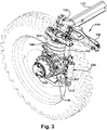
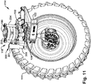
- the suspension reduction mechanism 100 may be utilized for increased operator comfort and agricultural vehicle stability. It may be utilized in a single spindle suspension application as shown in FIGURES 11-17 . It may also be used in a dual spindle suspension application, as shown for example in FIGURES 2-10 and 18 . Further, the agricultural vehicle suspension reduction mechanism 100 may be utilized on one, two, three, or all four ground engaging members 111 of the agricultural vehicle 102. The agricultural vehicle suspension reduction mechanism 100 may be used in a steerable application, as illustrated for example in FIGURES 2-17 . In other implementations, the agricultural vehicle suspension reduction mechanism 100 may be used in a nonsteerable application as shown in FIGURE 18 . Steerable applications may be utilized with a single spindle suspension application or for a dual spindle suspension application. Nonsteerable applications may be utilized with a single spindle suspension application or for a dual spindle suspension application.
- a mechanical, electromagnetic, hydraulic, pneumatic, or electromechanical stop body 200 may be one example of a component utilized to limit axial travel of a suspension assembly 118.
- the stop body 200 may be adjustable.
- One nonlimiting example of the stop body 200 may be a cylinder 201. It should be understood that the cylinder 201 may be operably connected to a first spindle 202.
- the first spindle 202 may be a steering spindle 170, 172 as described below.
- the first spindle 202 may be one of the suspension spindles 132, 232, 234 such as for example the single spindle suspension 132 or the dual spindle suspension 232, 234.
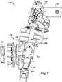
- transversely adjustable wheel axle assemblies one of which is shown at 114 may be slidably received in tubular frame members (not shown) and support a suspension assembly 118.
- the suspension assembly 118 may be steerable or nonsteerable.
- the suspension assembly 118 may be generally free of shock absorbers or dampers in one nonlimiting example.
- the suspension assembly 18 may comprise a tube 122 having an inner end slidably received by the member 116.
- the tube 122 may be connected to a hydraulic tread adjust cylinder (not shown) for adjusting the vehicle tread.
- a knee joint 128 may be connected to the outermost end of the tube 122 and may comprise an upright journal area 130 slidably and rotatably mounting an upright strut shaft or suspension spindle 132 having a shaft axis 132 a .
- the lower end of the strut shaft 32 may be fixed to a wheel support and motor housing 134, which may carry a hydraulically driven and steerable ground engaging member or wheel 111.
- the upper end of the shaft 132 may be fixed to an upper mount or spindle cap 136, and a spring 140 or other spring type of device connected to the top of the upper mount 136 may provide spring cushioning for the suspension spindle and housing 134.
- Any spring 140 may be utilized with sound engineering judgment, including without limitation, an air spring, a coil spring, a leaf spring, or a nitrogen accumulator, which may be an accumulator used as a spring hydraulically.
- the spring 140 may be confingured to be utilized with a compressible fluid, such as air, for example.
- a steering arm 144 may be rotatably mounted at the journal area 130 in an enlarged bore 146 and may slidably receive a central portion of the suspension spindle 132.
- the strut shaft 132 may be free to move axially relative to the steering arm 144 so that the vertical position of the steering arm 144 may remain constant relative to the knee joint 128.
- a steering cylinder arm 150 may be fixed to the knee joint 128 by bolts or other fasteners and may extend in a fore-and-aft direction therefrom to a base end connection at 154 to a steering cylinder 156.
- the cylinder 156 may extends from the base end connection at 154 to a rod end connection at 158 with a radially projecting steering member 64 on the steering arm 144.
- the steering arm 144 may support the lower ends of first and second upright steering spindles 170 and 172 generally parallel to the axis 132 a outwardly of the spring 140.
- the spindles 170 and 172 may be fixed to the steering arm 144 by bolts 176 and a taper lock and extend upwardly to a location above the spring 140.
- An uppermost spindle spacer and spring support 180 may be bolted to the tops of the spindles 170 and 172, and the spring 140 may be contained between the upper mount 36 and the support 80.
- the upper mount 36 may comprise guides or spindle bracket 182 and 184 slidably received over the outer circumference of the spindles 170 and 172 for constraining the upper mount 136 for rotation in unison with the steering arm 144.
- the upper end of the strut shaft 132 may be connected to the upper mount 136 by a taper lock and a bolt and washer assembly 90 and may be keyed at 192 for constraining the strut shaft 132 for rotation with the upper mount 136. Therefore, steering torque may be transferred from the steering arm 144 through the spindles 170 and 172 and through the upper mount 136 to the strut shaft 132. As the steering cylinder 156 is extended and retracted, the strut shaft 132 will rotate in the journal area 130 about the axis 132 a with the steering arm 44 to steer the housing 34 and attached drive wheel structure.
- the steering spindles 170 and 172 thereby may constrain the strut shaft 132 to maintain a constant angular relationship with the steering arm 144 while permitting the strut shaft 132 to move up and down in the journal area 130 and in the bore in the steering arm 144 to compress and relax the spring 140 as the wheel structure moves over the surface of the ground or as the weight supported by the wheel structure changes. Bumpers may provide protection for the suspension at the extreme positions of the strut shaft 132.
- an agricultural vehicle suspension 100 may comprise the first spindle 202.
- the first spindle 202 may be operably coupled with the spring 140 in a spindle axial direction S-S.
- the cylinder 201 may be operably coupled to the first spindle 202 in a stop body axial direction C-C.
- the cylinder 201 may be configured to limit an axial length of travel of the suspension assembly 120 relative to the first spindle 202.
- the spindle axial direction S-S may be substantially parallel to the stop body axial direction C-C.
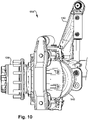
- the stop body 200 may be operably connected to a cylinder bracket 210.
- the cylinder bracket 210 may be operably coupled to the spindles brackets 182, 184.
- the cylinder bracket 210 may be oriented substantially orthogonal to the spindle brackets 182, 184 such that the cylinder bracket 210 is substantially parallel in whole or in part to the cylinder 201.
- the cylinder bracket 210 may be operably connected to the spindle brackets 182, 184.
- the cylinder bracket 210 may be integrated with the spindle brackets 182, 184 to form a single unitary piece.
- a stop bracket 212 may be disposed toward a bottom portion of the first spindle 202. In one implementation, the stop bracket 212 may be proximate to or integral with the steering arm 144. In another example implementation shown in FIGURE 18 , the stop bracket 212 may be proximate to or integral with a lower spindle stability bracket 240.
- a first axial length of travel may be defined by a portion of, or the full length of, one of the steering spindles 170, 172 extending from the upper portion proximate the spring support 180 to the lower portion proximate the steering arm 144 and/or stop bracket 212 and/or lower spindle stability bracket 240.
- the stop body 200 may be any mechanical, electromechanical, electromagnetic, hydraulic or pneumatic component configured to limit the axial length of travel of the suspension assembly 118 relative to the steering spindles 170, 172. In another implementation, the stop body 200 may be configured to limit the axial length of travel of the suspension assembly 118 relative to the suspension spindles 132, 232, 234. Examples of the stop body 200 may include without limitation, the cylinder 201, a telescoping body, a bar, a collar, or other body configured to limit the axial length of travel of the suspension assembly 118.
- the stop body 200 can take other configurations, such as applying a perpendicular, substantially perpendicular or angular force to one of the spindles to restrict the axial length of travel of the suspension.
- the stop body 200 may be a solenoid-actuated pin to lock suspension travel in one or both directions.
- the cylinder 201 may take the form of a single acting hydraulic cylinder, which may comprise an extendable ram portion 204. The ram portion may be threadedly engaged with the cylinder 201 in one example.
- the cylinder 201 may also be a double acting cylinder.
- the cylinder 201 may be hydraulic or pneumatic.
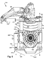
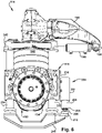
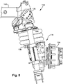
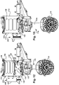
- the cylinder 201 may have extended position as shown in FIGURES 2-7 , 11 , 15-19 and a retracted position as shown in FIGURES 8 , and 12-14 .
- a bottom 206 of the ram 204 may be configured to limit the axial length of travel of the suspension.
- the extendable ram portion may be extended at any extended position as desired or selected to limit the axial length of travel of the suspension.
- the ram portion may be fully extended.
- the ram portion 204 may be extended half way.
- the ram portion 204 may be extendable by about three quarters of its extendable length.
- the adjustable position may be any length along the length of the ram portion 204. While the adjustability is described with respect to the ram portion 204, it should be understood that adjustability is contemplated for any implementation of the stop body 200 in order to limit the axial length of travel of the suspension.
- the bottom 206 of the ram portion 204 may contact the stop bracket 212.
- the bottom 206 may comprise a stopper 208 comprised of metal, such as steel, but not limited thereto, or a rubber material.
- the suspension assembly 118 when a portion of the stop body 200 contacts the stop bracket 212, the suspension assembly 118 the axial length of travel is restricted, and thus, the range of axial length of travel of the suspension assembly 118 is less than the overall axial length of travel.
- the agricultural vehicle suspension reduction mechanism 100 may be selectably engageable for on-road agricultural vehicle travel.
- the stop body 200 such as for example, the cylinder 201, may be selectably engageable for on-road agricultural vehicle travel.
- the operator may desire to have the full length of axial travel of the suspension assembly 118 to compensate for uneven terrain, such as bumps, holes, or undulations.
- on-road travel may have a more even underlying surface and higher agricultural vehicle velocity, so limiting the length of axial travel of the suspension assembly 118 may provide for greater agricultural vehicle stability and operator comfort.
- the engagability of the agricultural vehicle suspension reduction mechanism 100 may be manual or it may be automatic.
- a steering sensor may be actuated by one or more of a steering sensor, a transmission, or a switch that may communicate with a controller (not shown) to send a signal to the stop body 200.
- a controller not shown
- An operator may select a road speed with a cruise control feature of the agricultural vehicle 102.
- the agricultural vehicle suspension reduction mechanism 100 may automatically engage for road transport based on selected velocity or current velocity. Likewise, in the field it could be selectable in a side hill or turn condition.
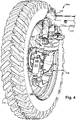
- the spring 140 may have a centered position ( FIGURE 12 ), an expanded position ( FIGURE 13 ), and a compressed position ( FIGURES 14 and 15 ).
- the centered, compressed and expanded positions are illustrated in an implementation of a single suspension spindle steerable suspension assembly 118. It should be understood that the centered, compressed, and expanded positions may also be applicable to a dual suspension spindle steerable assembly as shown in FIGURES 2-10 .
- the centered, compressed, and expanded positions may also be applicable to a dual suspension spindle nonsteerable assembly as shown in FIGURE 18 .
- the centered, compressed, and expanded positions may also be applicable to a single suspension spindle non steerable assembly.
- the spindle axial length of travel may be shown by the arrow S-S.
- the spindle axial length of travel may be a length, for example, of 200 mm or any other length chosen with sound engineering judgment.
- the spindle brackets 182, 184 may be positioned at about a midway position on the steering spindles 170, 172.
- FIGURE 13 also illustrates an example of the stop body being in a retracted position such that when the spring 140 is in an expanded position, there is no or little restriction on the spindle axial length of travel.
- FIGURE 14 illustrates an example of the spring 140 being pressurized, as in the case when the wheel encounters a bump in the terrain.
- the suspension assembly 118 is able to travel the axial length of travel without restriction since the stop body 200 is in a retracted position.
- the spring 140 is in the compressed position, but the stop body 200, such as the cylinder 201, is in the extended position.
- the ram portion 204 may be secured in the extended position. As such, as the spring 140 returns to its centered position or the expanded position, as shown in FIGURE 16 , the spindle axial length of travel is reduced because the ram portion may function as a rigid stop to prevent the spring 140 from expanding further. In the example, the spindle axial length of travel would be less than 200 mm, or less than the other chosen spindle axial distance. As shown in FIGURE 17 , the extended ram portion 204 may be secured or locked in position as the spring 140 is the in the compressed position.
- the ram portion 204 is disposed to contact the stop bracket 212 to reduce or minimize the axial length of travel along the steering spindles 170, 172, which in turn provides greater stability to the agricultural vehicle and operator comfort.
- the agricultural vehicle suspension reduction mechanism 100 is a nonsteerable dual spindle suspension assembly.
- the first spindle 202 may be one of the dual suspension spindles 232, 234.
- the suspension assembly 118 may travel axially about the dual suspension spindles 232, 234.
- An upper spindle support bracket 242 may surround each of the dual suspension spindles 232, 234 to provide stability and allow ease of axial travel relative to the suspension spindles.
- the stop body 200 which may take the form of the cylinder 201, may be operatively connected to the first spindle 202.
- the stop body 200 such as the cylinder 201, may be operably connected to one of the dual suspension spindles 232, 234.
- the ram portion 204 may restrict or limit axial travel about the suspension spindles 232, 234 by contacting the stop bracket 212, which may be part of the lower stability spindle bracket 240.
- the agricultural vehicle suspension reduction mechanism may be modular such that its components as described herein may be added to an existing suspension assembly.
- a method for limiting axial travel of a suspension utilizing the example implementations described herein may comprise the steps of applying pressure to the spring and then compressing the spring.
- the length of axial suspension travel may then be defined.
- the cylinder or stop body may be actuated to move a ram portion to an extended position.
- the extended cylinder position being in an axial direction parallel to the axial suspension travel, which may then reduce reducing the length of axial suspension travel.
- the method then may comprise the steps of decreasing pressure in the spring. This may then extend the spring to a centered position.
- the stop body or cylinder may be maintained in the extended position to maintain the reduced length of axial travel.
- the stop body may remain extended as the spring moves among the compressed, centered, and expanded positions to reduce or restrict the axial length of travel.
- the method may further comprise the step of retracting the cylinder into an unactuated position. As previously described, the method may comprise the step of the stop body contacting the stop bracket to reduce or restrict the axial length of travel.
- exemplary is used herein to mean serving as an example, instance or illustration. Any aspect or design described herein as “exemplary” is not necessarily to be construed as advantageous over other aspects or designs. Rather, use of the word exemplary is intended to present concepts in a concrete fashion.
- the term “or” is intended to mean an inclusive “or” rather than an exclusive “or.” That is, unless specified otherwise, or clear from context, "X employs A or B” is intended to mean any of the natural inclusive permutations. That is, if X employs A; X employs B; or X employs both A and B, then "X employs A or B" is satisfied under any of the foregoing instances.
- At least one of A and B and/or the like generally means A or B or both A and B.
- the articles “a” and “an” as used in this application and the appended claims may generally be construed to mean “one or more” unless specified otherwise or clear from context to be directed to a singular form.
Landscapes
- Engineering & Computer Science (AREA)
- Mechanical Engineering (AREA)
- Chemical & Material Sciences (AREA)
- Combustion & Propulsion (AREA)
- Transportation (AREA)
- Vehicle Body Suspensions (AREA)
Applications Claiming Priority (1)
| Application Number | Priority Date | Filing Date | Title |
|---|---|---|---|
| US17/084,059 US11642928B2 (en) | 2020-10-29 | 2020-10-29 | Self-propelled sprayer suspension travel reduction mechanism |
Publications (2)
| Publication Number | Publication Date |
|---|---|
| EP3992000A1 true EP3992000A1 (de) | 2022-05-04 |
| EP3992000B1 EP3992000B1 (de) | 2025-01-01 |
Family
ID=78085559
Family Applications (1)
| Application Number | Title | Priority Date | Filing Date |
|---|---|---|---|
| EP21201284.3A Active EP3992000B1 (de) | 2020-10-29 | 2021-10-06 | Aufhängung für landwirtschaftliches fahrzeug |
Country Status (6)
| Country | Link |
|---|---|
| US (1) | US11642928B2 (de) |
| EP (1) | EP3992000B1 (de) |
| AU (1) | AU2021240109A1 (de) |
| BR (1) | BR102021014680A2 (de) |
| CA (1) | CA3130932A1 (de) |
| DK (1) | DK3992000T3 (de) |
Families Citing this family (4)
| Publication number | Priority date | Publication date | Assignee | Title |
|---|---|---|---|---|
| ES2985198T3 (es) * | 2020-09-10 | 2024-11-04 | Monchiero & C S N C | Máquina cosechadora para cosechar frutos del suelo y método de control de la misma |
| KR20230130337A (ko) * | 2022-03-03 | 2023-09-12 | 현대자동차주식회사 | 차량의 코너 모듈용 롤 제어 시스템 |
| DE102023129670A1 (de) | 2023-10-27 | 2025-04-30 | Amazonen-Werke H. Dreyer SE & Co. KG | Landwirtschaftliches Fahrzeug mit Einzelradaufhängung |
| DE102023129658A1 (de) | 2023-10-27 | 2025-04-30 | Amazonen-Werke H. Dreyer SE & Co. KG | Einzelradaufhängung |
Citations (4)
| Publication number | Priority date | Publication date | Assignee | Title |
|---|---|---|---|---|
| GB2306415A (en) * | 1995-10-17 | 1997-05-07 | Deere & Co | Single wheel sliding pillar suspension and steering for an agricultural vehicle |
| US20090127812A1 (en) * | 2005-12-16 | 2009-05-21 | Copsey Charles R | Adjustable-height suspension system |
| US20200130741A1 (en) * | 2018-10-24 | 2020-04-30 | Agco Corporation | Mounting assembly for a steerable wheel with varaible track width |
| US20200317486A1 (en) * | 2019-04-05 | 2020-10-08 | Oshkosh Corporation | Oscillating axle for lift device |
Family Cites Families (5)
| Publication number | Priority date | Publication date | Assignee | Title |
|---|---|---|---|---|
| DE60120173T2 (de) * | 2000-07-17 | 2007-06-06 | Peugeot Citroen Automobiles S.A. | Hubbegrenzung für einen stossdämpfer eines kraftfahrzeuges und herstellverfahren dafür |
| US7168717B2 (en) | 2005-01-28 | 2007-01-30 | Deere & Company | High clearance vehicle suspension with twin spindles for transferring steering torque |
| US7717443B1 (en) * | 2008-12-03 | 2010-05-18 | Deere & Company | High-clearance vehicle suspension with spacer arrangement mountable between spindle and wheel hub mounting bracket for adjusting working clearance |
| US8534686B1 (en) * | 2010-12-30 | 2013-09-17 | Agco Corporation | Independent strut suspension |
| DE102020105378A1 (de) * | 2020-02-28 | 2021-09-02 | Horsch Leeb Application Systems Gmbh | Lenkbare Einzelradaufhängung mit zusätzlichem Träger |
-
2020
- 2020-10-29 US US17/084,059 patent/US11642928B2/en active Active
-
2021
- 2021-07-26 BR BR102021014680-0A patent/BR102021014680A2/pt unknown
- 2021-09-15 CA CA3130932A patent/CA3130932A1/en active Pending
- 2021-09-27 AU AU2021240109A patent/AU2021240109A1/en active Pending
- 2021-10-06 EP EP21201284.3A patent/EP3992000B1/de active Active
- 2021-10-06 DK DK21201284.3T patent/DK3992000T3/da active
Patent Citations (4)
| Publication number | Priority date | Publication date | Assignee | Title |
|---|---|---|---|---|
| GB2306415A (en) * | 1995-10-17 | 1997-05-07 | Deere & Co | Single wheel sliding pillar suspension and steering for an agricultural vehicle |
| US20090127812A1 (en) * | 2005-12-16 | 2009-05-21 | Copsey Charles R | Adjustable-height suspension system |
| US20200130741A1 (en) * | 2018-10-24 | 2020-04-30 | Agco Corporation | Mounting assembly for a steerable wheel with varaible track width |
| US20200317486A1 (en) * | 2019-04-05 | 2020-10-08 | Oshkosh Corporation | Oscillating axle for lift device |
Also Published As
| Publication number | Publication date |
|---|---|
| US11642928B2 (en) | 2023-05-09 |
| CA3130932A1 (en) | 2022-04-29 |
| BR102021014680A2 (pt) | 2022-05-10 |
| AU2021240109A1 (en) | 2022-05-19 |
| EP3992000B1 (de) | 2025-01-01 |
| US20220134826A1 (en) | 2022-05-05 |
| DK3992000T3 (da) | 2025-03-24 |
Similar Documents
| Publication | Publication Date | Title |
|---|---|---|
| EP3992000B1 (de) | Aufhängung für landwirtschaftliches fahrzeug | |
| US7168717B2 (en) | High clearance vehicle suspension with twin spindles for transferring steering torque | |
| US8020648B2 (en) | Windrower tractor with rear wheel suspension | |
| US5597172A (en) | Sprayer suspension and steering | |
| US5364114A (en) | Vehicle steering and suspension system | |
| EP2658735B1 (de) | Gestängehebemechanismus für geländefahrzeug | |
| US9884662B2 (en) | Suspension and lock-out systems for a partially tracked vehicle | |
| EP3871909B1 (de) | Mobile landmaschine | |
| US10517285B2 (en) | Vehicle with chassis height adjustment | |
| US9982413B2 (en) | Cab suspension system for a work vehicle | |
| US10766329B2 (en) | Vehicle with chassis height adjustment having floating strut rods | |
| US11524541B2 (en) | Hydraulic suspension system for off-road vehicles | |
| DE112004002483T5 (de) | Fahrzeug mit beweglicher und nach innen kippender Sicherheitskarosserie | |
| US6843046B2 (en) | Support wheel assembly for an agricultural implement on an agricultural machine | |
| EP3672817A1 (de) | Radaufhängung für ein kraftfahrzeug | |
| WO2019037946A1 (de) | Fahrzeugachse mit einer zentral angeordneten antriebseinheit | |
| US20220258552A1 (en) | Integrated suspension and clearance assembly | |
| WO2023223363A1 (en) | Agricultural vehicle | |
| MXPA96002361A (en) | Direction and suspension of rociad |
Legal Events
| Date | Code | Title | Description |
|---|---|---|---|
| PUAI | Public reference made under article 153(3) epc to a published international application that has entered the european phase |
Free format text: ORIGINAL CODE: 0009012 |
|
| STAA | Information on the status of an ep patent application or granted ep patent |
Free format text: STATUS: THE APPLICATION HAS BEEN PUBLISHED |
|
| AK | Designated contracting states |
Kind code of ref document: A1 Designated state(s): AL AT BE BG CH CY CZ DE DK EE ES FI FR GB GR HR HU IE IS IT LI LT LU LV MC MK MT NL NO PL PT RO RS SE SI SK SM TR |
|
| STAA | Information on the status of an ep patent application or granted ep patent |
Free format text: STATUS: REQUEST FOR EXAMINATION WAS MADE |
|
| 17P | Request for examination filed |
Effective date: 20221104 |
|
| RBV | Designated contracting states (corrected) |
Designated state(s): AL AT BE BG CH CY CZ DE DK EE ES FI FR GB GR HR HU IE IS IT LI LT LU LV MC MK MT NL NO PL PT RO RS SE SI SK SM TR |
|
| GRAP | Despatch of communication of intention to grant a patent |
Free format text: ORIGINAL CODE: EPIDOSNIGR1 |
|
| STAA | Information on the status of an ep patent application or granted ep patent |
Free format text: STATUS: GRANT OF PATENT IS INTENDED |
|
| INTG | Intention to grant announced |
Effective date: 20240918 |
|
| GRAS | Grant fee paid |
Free format text: ORIGINAL CODE: EPIDOSNIGR3 |
|
| GRAA | (expected) grant |
Free format text: ORIGINAL CODE: 0009210 |
|
| STAA | Information on the status of an ep patent application or granted ep patent |
Free format text: STATUS: THE PATENT HAS BEEN GRANTED |
|
| AK | Designated contracting states |
Kind code of ref document: B1 Designated state(s): AL AT BE BG CH CY CZ DE DK EE ES FI FR GB GR HR HU IE IS IT LI LT LU LV MC MK MT NL NO PL PT RO RS SE SI SK SM TR |
|
| REG | Reference to a national code |
Ref country code: GB Ref legal event code: FG4D |
|
| REG | Reference to a national code |
Ref country code: CH Ref legal event code: EP |
|
| REG | Reference to a national code |
Ref country code: DE Ref legal event code: R096 Ref document number: 602021024151 Country of ref document: DE |
|
| REG | Reference to a national code |
Ref country code: IE Ref legal event code: FG4D |
|
| REG | Reference to a national code |
Ref country code: DK Ref legal event code: T3 Effective date: 20250320 |
|
| REG | Reference to a national code |
Ref country code: NL Ref legal event code: FP |
|
| REG | Reference to a national code |
Ref country code: LT Ref legal event code: MG9D |
|
| REG | Reference to a national code |
Ref country code: AT Ref legal event code: MK05 Ref document number: 1755894 Country of ref document: AT Kind code of ref document: T Effective date: 20250101 |
|
| PG25 | Lapsed in a contracting state [announced via postgrant information from national office to epo] |
Ref country code: FI Free format text: LAPSE BECAUSE OF FAILURE TO SUBMIT A TRANSLATION OF THE DESCRIPTION OR TO PAY THE FEE WITHIN THE PRESCRIBED TIME-LIMIT Effective date: 20250101 |
|
| PG25 | Lapsed in a contracting state [announced via postgrant information from national office to epo] |
Ref country code: PL Free format text: LAPSE BECAUSE OF FAILURE TO SUBMIT A TRANSLATION OF THE DESCRIPTION OR TO PAY THE FEE WITHIN THE PRESCRIBED TIME-LIMIT Effective date: 20250101 |
|
| PG25 | Lapsed in a contracting state [announced via postgrant information from national office to epo] |
Ref country code: ES Free format text: LAPSE BECAUSE OF FAILURE TO SUBMIT A TRANSLATION OF THE DESCRIPTION OR TO PAY THE FEE WITHIN THE PRESCRIBED TIME-LIMIT Effective date: 20250101 |
|
| PG25 | Lapsed in a contracting state [announced via postgrant information from national office to epo] |
Ref country code: IS Free format text: LAPSE BECAUSE OF FAILURE TO SUBMIT A TRANSLATION OF THE DESCRIPTION OR TO PAY THE FEE WITHIN THE PRESCRIBED TIME-LIMIT Effective date: 20250501 Ref country code: NO Free format text: LAPSE BECAUSE OF FAILURE TO SUBMIT A TRANSLATION OF THE DESCRIPTION OR TO PAY THE FEE WITHIN THE PRESCRIBED TIME-LIMIT Effective date: 20250401 |
|
| PG25 | Lapsed in a contracting state [announced via postgrant information from national office to epo] |
Ref country code: HR Free format text: LAPSE BECAUSE OF FAILURE TO SUBMIT A TRANSLATION OF THE DESCRIPTION OR TO PAY THE FEE WITHIN THE PRESCRIBED TIME-LIMIT Effective date: 20250101 |
|
| PG25 | Lapsed in a contracting state [announced via postgrant information from national office to epo] |
Ref country code: LV Free format text: LAPSE BECAUSE OF FAILURE TO SUBMIT A TRANSLATION OF THE DESCRIPTION OR TO PAY THE FEE WITHIN THE PRESCRIBED TIME-LIMIT Effective date: 20250101 Ref country code: PT Free format text: LAPSE BECAUSE OF FAILURE TO SUBMIT A TRANSLATION OF THE DESCRIPTION OR TO PAY THE FEE WITHIN THE PRESCRIBED TIME-LIMIT Effective date: 20250502 |
|
| PG25 | Lapsed in a contracting state [announced via postgrant information from national office to epo] |
Ref country code: GR Free format text: LAPSE BECAUSE OF FAILURE TO SUBMIT A TRANSLATION OF THE DESCRIPTION OR TO PAY THE FEE WITHIN THE PRESCRIBED TIME-LIMIT Effective date: 20250402 Ref country code: BG Free format text: LAPSE BECAUSE OF FAILURE TO SUBMIT A TRANSLATION OF THE DESCRIPTION OR TO PAY THE FEE WITHIN THE PRESCRIBED TIME-LIMIT Effective date: 20250101 |
|
| PG25 | Lapsed in a contracting state [announced via postgrant information from national office to epo] |
Ref country code: AT Free format text: LAPSE BECAUSE OF FAILURE TO SUBMIT A TRANSLATION OF THE DESCRIPTION OR TO PAY THE FEE WITHIN THE PRESCRIBED TIME-LIMIT Effective date: 20250101 |
|
| PG25 | Lapsed in a contracting state [announced via postgrant information from national office to epo] |
Ref country code: CZ Free format text: LAPSE BECAUSE OF FAILURE TO SUBMIT A TRANSLATION OF THE DESCRIPTION OR TO PAY THE FEE WITHIN THE PRESCRIBED TIME-LIMIT Effective date: 20250101 |
|
| PG25 | Lapsed in a contracting state [announced via postgrant information from national office to epo] |
Ref country code: SE Free format text: LAPSE BECAUSE OF FAILURE TO SUBMIT A TRANSLATION OF THE DESCRIPTION OR TO PAY THE FEE WITHIN THE PRESCRIBED TIME-LIMIT Effective date: 20250101 |
|
| REG | Reference to a national code |
Ref country code: DE Ref legal event code: R097 Ref document number: 602021024151 Country of ref document: DE |
|
| PG25 | Lapsed in a contracting state [announced via postgrant information from national office to epo] |
Ref country code: SM Free format text: LAPSE BECAUSE OF FAILURE TO SUBMIT A TRANSLATION OF THE DESCRIPTION OR TO PAY THE FEE WITHIN THE PRESCRIBED TIME-LIMIT Effective date: 20250101 |
|
| PG25 | Lapsed in a contracting state [announced via postgrant information from national office to epo] |
Ref country code: IT Free format text: LAPSE BECAUSE OF FAILURE TO SUBMIT A TRANSLATION OF THE DESCRIPTION OR TO PAY THE FEE WITHIN THE PRESCRIBED TIME-LIMIT Effective date: 20250101 |
|
| PG25 | Lapsed in a contracting state [announced via postgrant information from national office to epo] |
Ref country code: EE Free format text: LAPSE BECAUSE OF FAILURE TO SUBMIT A TRANSLATION OF THE DESCRIPTION OR TO PAY THE FEE WITHIN THE PRESCRIBED TIME-LIMIT Effective date: 20250101 |
|
| PG25 | Lapsed in a contracting state [announced via postgrant information from national office to epo] |
Ref country code: RO Free format text: LAPSE BECAUSE OF FAILURE TO SUBMIT A TRANSLATION OF THE DESCRIPTION OR TO PAY THE FEE WITHIN THE PRESCRIBED TIME-LIMIT Effective date: 20250101 |
|
| PG25 | Lapsed in a contracting state [announced via postgrant information from national office to epo] |
Ref country code: SK Free format text: LAPSE BECAUSE OF FAILURE TO SUBMIT A TRANSLATION OF THE DESCRIPTION OR TO PAY THE FEE WITHIN THE PRESCRIBED TIME-LIMIT Effective date: 20250101 |
|
| PLBE | No opposition filed within time limit |
Free format text: ORIGINAL CODE: 0009261 |
|
| STAA | Information on the status of an ep patent application or granted ep patent |
Free format text: STATUS: NO OPPOSITION FILED WITHIN TIME LIMIT |
|
| PGFP | Annual fee paid to national office [announced via postgrant information from national office to epo] |
Ref country code: NL Payment date: 20251026 Year of fee payment: 5 |
|
| 26N | No opposition filed |
Effective date: 20251002 |
|
| PGFP | Annual fee paid to national office [announced via postgrant information from national office to epo] |
Ref country code: DE Payment date: 20250919 Year of fee payment: 5 |
|
| PGFP | Annual fee paid to national office [announced via postgrant information from national office to epo] |
Ref country code: GB Payment date: 20251027 Year of fee payment: 5 |
|
| PGFP | Annual fee paid to national office [announced via postgrant information from national office to epo] |
Ref country code: DK Payment date: 20251027 Year of fee payment: 5 |
|
| PGFP | Annual fee paid to national office [announced via postgrant information from national office to epo] |
Ref country code: FR Payment date: 20251027 Year of fee payment: 5 |