EP3991663B1 - Mammography apparatus - Google Patents
Mammography apparatus Download PDFInfo
- Publication number
- EP3991663B1 EP3991663B1 EP21204434.1A EP21204434A EP3991663B1 EP 3991663 B1 EP3991663 B1 EP 3991663B1 EP 21204434 A EP21204434 A EP 21204434A EP 3991663 B1 EP3991663 B1 EP 3991663B1
- Authority
- EP
- European Patent Office
- Prior art keywords
- compression plate
- operation portion
- speed
- mammography apparatus
- case
- Prior art date
- Legal status (The legal status is an assumption and is not a legal conclusion. Google has not performed a legal analysis and makes no representation as to the accuracy of the status listed.)
- Active
Links
Images


Classifications
-
- A—HUMAN NECESSITIES
- A61—MEDICAL OR VETERINARY SCIENCE; HYGIENE
- A61B—DIAGNOSIS; SURGERY; IDENTIFICATION
- A61B6/00—Apparatus or devices for radiation diagnosis; Apparatus or devices for radiation diagnosis combined with radiation therapy equipment
- A61B6/04—Positioning of patients; Tiltable beds or the like
- A61B6/0407—Supports, e.g. tables or beds, for the body or parts of the body
- A61B6/0414—Supports, e.g. tables or beds, for the body or parts of the body with compression means
-
- A—HUMAN NECESSITIES
- A61—MEDICAL OR VETERINARY SCIENCE; HYGIENE
- A61B—DIAGNOSIS; SURGERY; IDENTIFICATION
- A61B6/00—Apparatus or devices for radiation diagnosis; Apparatus or devices for radiation diagnosis combined with radiation therapy equipment
- A61B6/50—Apparatus or devices for radiation diagnosis; Apparatus or devices for radiation diagnosis combined with radiation therapy equipment specially adapted for specific body parts; specially adapted for specific clinical applications
- A61B6/502—Apparatus or devices for radiation diagnosis; Apparatus or devices for radiation diagnosis combined with radiation therapy equipment specially adapted for specific body parts; specially adapted for specific clinical applications for diagnosis of breast, i.e. mammography
-
- A—HUMAN NECESSITIES
- A61—MEDICAL OR VETERINARY SCIENCE; HYGIENE
- A61B—DIAGNOSIS; SURGERY; IDENTIFICATION
- A61B6/00—Apparatus or devices for radiation diagnosis; Apparatus or devices for radiation diagnosis combined with radiation therapy equipment
- A61B6/54—Control of apparatus or devices for radiation diagnosis
Definitions
- the technology of the present disclosure relates to a mammography apparatus.
- a mammography apparatus that irradiates a breast of a subject with radiation and captures a radiation image of the breast.
- the mammography apparatus is provided with an imaging table on which the breast is placed and a compression plate which is disposed to face the imaging table and compresses the breast.
- the compression plate can be raised and lowered in a vertical direction with respect to the imaging table, and the breast is compressed by lowering the compression plate toward the imaging table.
- an operation portion operated to raise and lower the compression plate a button operation portion, a pedal operation portion, a rotation operation portion, and the like are known.
- the button operation portion and the pedal operation portion have two buttons or two foot pedals corresponding to a raising instruction and a lowering instruction, and are operated by a pressing operation of the button or a depressing operation of the pedal.
- Document US 2014/348291 A1 provides an X-ray imaging apparatus including an X-ray source to emit an X-ray onto a breast, a detector assembly configured to detect the X-ray transmitted through the breast, a compression paddle configured to compress the breast positioned on the detector assembly, a paddle manipulator configured to control the compression paddle according to a command, a degree-of-compression sensor configured to measure a degree of compression to which the breast is compressed by the compression paddle, and a pressure controller configured to supply a pressure corresponding to the measured degree of compression of the breast to the paddle manipulator.
- the operation direction is not along a movement direction of the compression plate in the vertical direction.
- the operation directions of the pressing operation of the button or the depressing operation of the pedal, and the rotation operation of the rotation knob or the jog dial are all significantly different from the vertical direction, which is the movement direction of the raising and lowering operation of the compression plate.
- the operation direction of the operation portion is not along the movement direction of the compression plate as described above, it is difficult to understand a correspondence between the operation direction of the operation portion and the movement direction of the compression plate.
- Document JP H04 64346 A discloses a mamma pressing mechanism for a mamma roentgenograph. When a lift lever is depressed in a first direction to lower a support member in a second direction, a mamma pressing plate lowers to a cassette while as it is lifted in a third direction, a pinion is turned freely and the support member rises in a fourth direction.
- a knob for fine adjustment is provided on the outer end of a rotating shaft to turn the pinion meshed with a rack direct manually and linked thereto.
- a pressing force of the mamma by the mamma pressing plate can be adjusted.
- a pinion, a rack and a spring are used for translating a movement of the lift lever and the knob into a movement of the mamma pressing plate.
- the present invention is to provide a mammography apparatus having better operability of a compression plate than the related art.
- the present invention relates to a mammography apparatus with the features of claim 1.
- the mammography apparatus further comprises a support portion that is connected to and moves together with the compression plate to be movable with respect to the imaging table, in which the operation portion is provided on the support portion.
- the mammography apparatus may comprise a support portion that supports the compression plate to be movable with respect to the imaging table, and a movable portion that is disposed between the compression plate and the support portion and is moved in the vertical direction together with the compression plate, in which the operation portion is provided on the support portion.
- the mammography apparatus further comprises an actuator that drives the compression plate, in which the actuator is activated in response to an operation of the operation portion, and the compression plate is moved by driving force generated by the actuator.
- the mammography apparatus further comprises a processor that controls the actuator to change a movement speed of the compression plate.
- the mammography apparatus further comprises a displacement amount detection unit that detects a displacement amount of the operation portion, in which the processor changes the movement speed of the compression plate based on the displacement amount detected by the displacement amount detection unit.
- the mammography apparatus further comprises a height detection unit that detects a height of the compression plate with respect to the imaging table, in which the processor changes the movement speed of the compression plate in response to the height of the compression plate.
- the processor sets an initial speed of the compression plate in a case in which the compression plate is raised from a state in which the compression plate is positioned at a relatively low position to be faster than an initial speed of the compression plate in a case in which the compression plate is raised from a state in which the compression plate is positioned at a relatively high position.
- the processor sets an initial speed of the compression plate in a case in which the compression plate is lowered from a state in which the compression plate is positioned at a relatively high position to be faster than an initial speed of the compression plate in a case in which the compression plate is lowered from a state in which the compression plate is positioned at a relatively low position.
- the mammography apparatus further comprises a displacement speed detection unit that detects a displacement speed of the operation portion, in which the processor sets the movement speed of the compression plate to be faster as the displacement speed of the operation portion is faster.
- the mammography apparatus further comprises a pressure detection unit that detects a pressure received by the compression plate from the breast.
- the processor sets a rate of change in speed, which is a ratio of a change amount of the movement speed of the compression plate to a unit displacement amount of the operation portion, to be smaller as the pressure is larger.
- the processor stops movement of the compression plate in a case in which the pressure detected by the pressure detection unit is equal to or larger than a preset threshold value.
- the mammography apparatus further comprises a load increasing unit that increases a load for operating the operation portion as a displacement amount of the operation portion is larger.
- the operation portion is a cantilever type lever having one end, which is a free end, and at least the free end is displaced along the movement direction of the compression plate.
- the operation portion stretches in an anteroposterior direction or a lateral direction.
- the operation portion rotates about a fulcrum provided on a base end side.
- the operation portion includes a main shaft portion that extends from the base end side to a free end side, and a protruding portion that is provided on the main shaft portion and protrudes to at least one of a lower side or an upper side with an axial direction of the main shaft portion as a reference.
- the protruding portion includes a first protruding portion that protrudes to the lower side of the main shaft portion, and a second protruding portion that protrudes to the upper side of the main shaft portion.
- the protruding portion has a hook shape or a ring shape.
- FIG. 1 shows an example of an overall configuration of a mammography apparatus according to a first embodiment.
- a mammography apparatus 10 uses a breast M of a subject (see Fig. 3 ) as an object.
- the mammography apparatus 10 is a radiography apparatus that irradiates the breast M with radiation (for example, X-rays or ⁇ -rays) and captures a radiation image of the breast M.
- radiation for example, X-rays or ⁇ -rays
- the mammography apparatus 10 comprises an apparatus body 11 and a control device 12.
- the apparatus body 11 is installed in a radiography room of a medical facility, for example.
- the control device 12 is installed in a control room adjacent to the radiography room, for example.
- the control device 12 is a desktop-type personal computer, for example.
- the control device 12 is communicably connected to an image database server (not shown) via a network (not shown) such as a local area network (LAN).
- LAN local area network
- the apparatus body 11 includes a stand 20 and an arm 21.
- the stand 20 is configured by a seat 20A installed on a floor of the radiography room and a support column 20B extending in a height direction from the seat 20A.
- the arm 21 has a substantially C-shape as viewed from the side, and is connected to the support column 20B. Since the arm 21 is movable in the height direction with respect to the support column 20B, a height thereof can be adjusted in response to a height of the subject. In addition, the arm 21 can rotate around a rotation shaft perpendicular to the support column 20B.
- the arm 21 is configured by a radiation source housing portion 22, an imaging table 23, and a body portion 24.
- a radiation source 25 is housed in the radiation source housing portion 22.
- the breast M of the subject is placed on the imaging table 23.
- a radiation detector 26 is housed in the imaging table 23.
- the body portion 24 integrally connects the radiation source housing portion 22 and the imaging table 23.
- the body portion 24 holds the radiation source housing portion 22 and the imaging table 23 at facing positions.
- Handrails 27 held by the subject by the hands are provided on the both sides of the body portion 24.
- the radiation source 25 irradiates the breast M placed on the imaging table 23 with the radiation.
- the radiation emitted from the radiation source 25 is transmitted through a compression plate 33 and then incident on the breast M.
- the radiation detector 26 detects the radiation transmitted through the breast M and outputs the radiation image.
- the radiation detector 26 is called a flat panel detector (FPD).
- the radiation detector 26 may include a scintillator that converts the radiation into visible light, and may be an indirect conversion type that converts the visible light emitted by the scintillator into an electric signal, or a direct conversion type that directly converts the radiation into an electric signal.
- An irradiation field limiter 31 is provided between the radiation source housing portion 22 and the imaging table 23.
- the irradiation field limiter 31 is also called a collimator, and defines an irradiation field of the radiation to the imaging table 23.
- a face guard 32 is attached to the radiation source housing portion 22.
- the face guard 32 is made or coated with a material through which the radiation is not transmitted, and protects a face of the subject from the radiation.
- the compression plate 33 which interposes and compresses the breast M with the imaging table 23, is provided between the imaging table 23 and the irradiation field limiter 31.
- the compression plate 33 is made of a material through which the radiation is transmitted.
- the compression plate 33 is disposed at a position facing the imaging table 23.
- the compression plate 33 has a box shape with an open upper surface side.
- the compression plate 33 may have another shape, such as a flat plate shape.
- the body portion 24 of the arm 21 supports the compression plate 33 to be movable with respect to the imaging table 23.
- the body portion 24 is an example of a "support portion” according to the technology of the present disclosure.
- a movable portion 34 is disposed between the compression plate 33 and the body portion 24.
- the movable portion 34 is held by a rail 28 provided on the body portion 24 to be movable slidingly.
- the rail 28 stretches in a vertical direction.
- the compression plate 33 is attached to the movable portion 34.
- the movable portion 34 is moved in the vertical direction together with the compression plate 33 by a drive mechanism, which will be described below.
- the vertical direction is a direction in which the compression plate 33 is moved toward the imaging table 23 (downward direction) and a direction in which the compression plate 33 is separated from the imaging table 23 (upward direction).
- the compression plate 33 is configured to be movable with respect to the imaging table 23.
- Fig. 2 is a partially enlarged view of the mammography apparatus 10.
- the mammography apparatus 10 is provided with an operation portion 40 that moves the compression plate 33 in the vertical direction.
- the operation portion 40 is provided separately from the compression plate 33, and is displaced along a movement direction of the compression plate 33.
- the operation portion 40 is provided on the movable portion 34.
- the operation portion 40 is operated in a case in which an operator, such as a radiologist, compresses the breast with respect to the imaging table 23 with the compression plate 33 to perform positioning of the breast M during radiography.
- the operation portion 40 is operated in a case in which the operator releases the compression of the breast M by the compression plate 33 after the radiography is terminated.
- the operation portion 40 is a cantilever type lever having one end, which is a free end, and the free end is displaced along the movement direction of the compression plate 33.
- the operation portion 40 is configured by a rod-shaped main shaft portion 40A and a spherical-shaped grip portion 40B.
- the grip portion 40B is attached to one end (that is, free end) of the main shaft portion 40A.
- a rotation shaft 41 is provided at the other end (that is, base end) of the main shaft portion 40A.
- the rotation shaft 41 is disposed inside the movable portion 34.
- the operation portion 40 is attached to the movable portion 34 such that the main shaft portion 40A stretches toward a side of the subject who places the breast M on the imaging table 23.
- the main shaft portion 40A obliquely stretches in the upward direction toward the side of the subject. That is, assuming that a direction of a position of the subject who places the breast on the imaging table 23 is anterior and an opposite direction thereof is posterior, the operation portion 40 having a lever shape stretches in an anteroposterior direction.
- the anteroposterior direction is, in other words, a depth direction of the mammography apparatus 10, and the operation portion 40 stretches in the depth direction of the mammography apparatus 10.
- the anteroposterior direction which is a stretching direction of the operation portion 40, is a concept including a case other than a case of being parallel to the floor (horizontal plane) as in the present example, and does not include a width direction and a perpendicular direction of the mammography apparatus 10.
- the stretching direction of the operation portion 40 at a neutral position (position indicated by a solid line in Fig. 3 ) in a state of not being operated is about 60° or less with respect to the horizontal plane, preferably 45° or less as in the present example.
- the operation portion 40 rotates with the rotation shaft 41 provided on a base end side as a fulcrum.
- the grip portion 40B is displaced in a direction along the movement direction of the compression plate 33, that is, in the vertical direction.
- the operator can displace the grip portion 40B in the vertical direction in a state of gripping the grip portion 40B.
- the compression plate 33 In a case in which the grip portion 40B is displaced in the downward direction, the compression plate 33 is moved (that is, lowered) toward the imaging table 23.
- the compression plate 33 moves (that is, raised) in a direction separated from the imaging table 23.
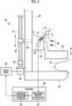
- Fig. 3 shows an example of configurations of the drive mechanism of the compression plate 33 and a processor that controls movement of the compression plate 33.
- a drive mechanism 50 shown in Fig. 3 is a so-called electric linear actuator.
- the drive mechanism 50 is provided, for example, inside the body portion 24 and is activated by an operation of the operation portion 40.
- the drive mechanism 50 includes a rod screw 51, a nut 52, a coupling 53, a motor 54, and a motor driver 55.
- the rod screw 51 extends in the vertical direction along the rail 28 (see Fig. 2 ).
- the rod screw 51 is a trapezoidal screw, for example.
- the nut 52 is screwed with the rod screw 51.
- the movable portion 34 is connected to the nut 52 via a connection portion 56. The movable portion 34 is moved in the vertical direction together with the nut 52 by rotation of the rod screw 51.
- the compression plate 33 is moved together with the movable portion 34 by driving force generated by the drive mechanism 50 as the actuator.
- a processor 60 is configured by, for example, a central processing unit (CPU), a memory, and the like.
- the processor 60 realizes various functions by executing a process by the CPU based on a program stored in the memory.
- the processor 60 is provided, for example, inside the body portion 24.
- the processor 60 includes a displacement direction detection unit 61 and a compression plate movement controller 62.
- the displacement direction detection unit 61 detects a displacement direction of the operation portion 40 based on a detection signal output from a potentiometer 42 as an angle detection sensor connected to the rotation shaft 41 of the operation portion 40.
- the potentiometer 42 is provided inside the movable portion 34, and outputs the detection signal in response to an angle of the operation portion 40. Note that it is also possible to use an encoder as the angle detection sensor instead of the potentiometer 42.
- a state in which the operation portion 40 is positioned at the neutral position is shown by the solid line.
- the displacement direction detection unit 61 detects a case in which the grip portion 40B of the operation portion 40 is displaced in the downward direction from the neutral position as "displacement in a positive direction” and detects a case in which the grip portion 40B of the operation portion 40 is displaced in the upward direction from the neutral position as "displacement in a negative direction", and detects whether the displacement direction is positive or negative.
- the compression plate movement controller 62 controls the drive mechanism 50 based on the displacement direction detected by the displacement direction detection unit 61. Specifically, the compression plate movement controller 62 controls the motor driver 55 in response to the displacement direction detected by the displacement direction detection unit 61 to change a rotation direction of the motor 54. In a case in which the displacement direction is the positive direction (that is, downward direction), the compression plate movement controller 62 lowers the compression plate 33 together with the movable portion 34 by rotating the motor 54 clockwise. In addition, in a case in which the displacement direction is the negative direction (that is, upward direction), the compression plate movement controller 62 raises the compression plate 33 together with the movable portion 34 by rotating the motor 54 counterclockwise.
- the compression plate movement controller 62 determines whether or not the operation of the operation portion 40 is started (step S10). For example, the compression plate movement controller 62 determines that the operation of the operation portion 40 is started in a case in which the operation portion 40 is displaced from the neutral position.
- the compression plate movement controller 62 acquires the displacement direction detected by the displacement direction detection unit 61 (step S11). The compression plate movement controller 62 determines whether or not the acquired displacement direction is the downward direction (step S12). In a case in which it is determined that the displacement direction is the downward direction (step S12: YES), the compression plate movement controller 62 controls the drive mechanism 50 to lower the compression plate 33 (step S13). On the other hand, in a case in which it is determined that the displacement direction is the upward direction (step S12: NO), the compression plate movement controller 62 controls the drive mechanism 50 to raise the compression plate 33 (step S14).
- step S15 the compression plate movement controller 62 determines whether or not the operation of the operation portion 40 is terminated. For example, the compression plate movement controller 62 determines that the operation of the operation portion 40 is terminated in a case in which the operation portion 40 is returned to the neutral position. In a case in which it is determined that the operation of the operation portion 40 is not terminated (step S15: NO), the compression plate movement controller 62 returns the process to step S11.
- the compression plate movement controller 62 repeats the processes of steps S11 to S15 until it is determined that the operation of the operation portion 40 is terminated, and terminates the process in a case in which it is determined that the operation of the operation portion 40 is terminated (step S15: YES).
- the operator who operates the operation portion 40 need only operate the operation portion 40 in a direction in which the compression plate 33 is lowered.
- the operator who operates the operation portion 40 need only operate the operation portion 40 in a direction in which the compression plate 33 is raised.
- the operation portion is displaced along the movement direction of the compression plate, and thus the operation direction of the operation portion and the movement direction of the compression plate are substantially the same. Therefore, the operator can intuitively operate the operation portion. That is, the mammography apparatus according to the present embodiment has better operability of the compression plate as compared with an apparatus in the related art in which the operation direction of the operation portion and the movement direction of the compression plate are significantly different. Therefore, according to the technology of the present disclosure, it is possible to provide the mammography apparatus having better operability of the compression plate than the related art.
- the second embodiment is different from the first embodiment only in a functional configuration of the processor 60.
- Fig. 5 shows a configuration of the mammography apparatus according to the second embodiment.
- the processor 60 includes a displacement amount detection unit 63 and the compression plate movement controller 62.
- the compression plate movement controller 62 includes a speed controller 62A.
- the displacement amount detection unit 63 detects an angle ⁇ of the operation portion 40 based on the detection signal output from the potentiometer 42.
- the angle ⁇ represents a rotation angle of the operation portion 40 from the neutral position.
- the angle ⁇ has a "positive value” in a case in which the grip portion 40B of the operation portion 40 is displaced in the downward direction from the neutral position, and has a "negative value” in a case in which the grip portion 40B of the operation portion 40 is displaced in the upward direction from the neutral position. That is, the angle ⁇ is a concept including the "displacement direction" described in the first embodiment. Note that the angle ⁇ is an example of a "displacement amount" according to the technology of the present disclosure.
- the speed controller 62A obtains a speed V corresponding to the angle ⁇ as the displacement amount detected by the displacement amount detection unit 63, and controls the motor driver 55 such that the compression plate 33 is moved at the obtained speed V.
- the speed V has a "positive value” in a case in which the compression plate 33 is lowered, and has a “negative value” in a case in which the compression plate 33 is raised. That is, the speed V is a concept including the "movement direction" described in the first embodiment.
- the speed controller 62A controls a rotation speed (including the rotation direction) of the motor 54 via the motor driver 55 to change the speed V at which the compression plate 33 is moved.
- Fig. 6 shows an example of a relationship between the angle ⁇ and the speed V.
- the speed V has a proportional relationship with the angle ⁇ .
- the speed controller 62A obtains the speed V corresponding to the angle ⁇ detected by the displacement amount detection unit 63 based on the relationship between the angle ⁇ and the speed V shown in Fig. 6 .
- the speed controller 62A may store the relationship between the angle ⁇ and the speed V as a function to obtain the speed V based on the function.
- the speed controller 62A may store the relationship between the angle ⁇ and the speed V in the memory as a look up table (LUT), and obtain the speed V based on the LUT.
- LUT look up table
- the speed controller 62A performs a speed control using the relationship between the angle ⁇ and the speed V shown in Fig. 6 , the speed V of the compression plate 33 is changed in proportion to the displacement amount of the operation portion 40. That is, a rate of change in the speed V of the compression plate 33 with respect to a unit displacement amount of the operation portion 40 is fixed.
- Fig. 7 shows another example of the relationship between the angle ⁇ and the speed V.
- a relationship between the speed V and the angle ⁇ is non-linear, and the rate of change in the speed V is larger as the angle ⁇ is larger.
- the speed V is changed with respect to the angle ⁇ at a rate of change such as an exponential function, for example.
- Steps S20 to S24 shown in Fig. 8 are the same as steps S10 to S14 shown in Fig. 4 , and thus the description thereof will be omitted.
- the compression plate movement controller 62 acquires the angle ⁇ as the displacement amount detected by the displacement amount detection unit 63 (step S25).
- the speed controller 62A obtains the speed V based on the angle ⁇ acquired by the compression plate movement controller 62 (step S26). Then, the speed controller 62A controls the drive mechanism 50 such that the compression plate 33 is moved at the obtained speed V (step S27).
- the compression plate movement controller 62 determines whether or not the operation of the operation portion 40 is terminated (step S28). In a case in which it is determined that the operation of the operation portion 40 is not terminated (step S28: NO), the compression plate movement controller 62 returns the process to step S25. In a case in which it is determined that the operation of the operation portion 40 is terminated (step S28: YES), the compression plate movement controller 62 terminates the process.
- Fig. 9 describes an action of the mammography apparatus according to the second embodiment.
- Fig. 9 shows the change in the speed V in a case in which the angle ⁇ of the operation portion 40 is increased.
- the speed V of the compression plate 33 is increased from V 1 to V 2 .
- Fig. 9 shows a case in which the operation portion 40 is displaced in the downward direction, but the same applies to a case in which the operation portion 40 is displaced in the upward direction.
- the movement speed of the compression plate 33 is faster as the displacement amount of the operation portion 40 is larger, so that the operator can intuitively perform the operation.
- the third embodiment is different from the first embodiment in the functional configuration of the processor 60 and in that an encoder 57 is connected to the motor 54.
- Fig. 10 shows a configuration of the mammography apparatus according to the third embodiment.
- the processor 60 includes the displacement amount detection unit 63, a height detection unit 64, and the compression plate movement controller 62.
- the compression plate movement controller 62 includes the speed controller 62A and a speed adjustment unit 62B.
- the encoder 57 is connected to the motor 54.
- the displacement amount detection unit 63 and the speed controller 62A have the same functions as the displacement amount detection unit 63 and the speed controller 62A described in the second embodiment.
- the displacement amount detection unit 63 detects the angle ⁇ of the operation portion 40.
- the speed controller 62A obtains the speed V corresponding to the angle ⁇ detected by the displacement amount detection unit 63, and controls the motor driver 55 such that the compression plate 33 is moved at the obtained speed V.
- the encoder 57 converts a mechanical displacement amount of the rotation of the motor 54 into an electric signal and outputs the converted electric signal.
- the height detection unit 64 detects a height H of the compression plate 33 with respect to the imaging table 23 based on the output signal output from the encoder 57.
- the height H refers to an interval between the compression plate 33 and the imaging table 23.
- the height H of the compression plate 33 with respect to the imaging table 23 is higher as the interval between the compression plate 33 and the imaging table 23 is wider, and the height H of the compression plate 33 with respect to the imaging table 23 is lower as the interval therebetween is narrower.
- the output signal of the encoder 57 includes a pulse in response to the rotation of the motor 54.
- the height detection unit 64 counts the number of the pulses included in the output signal of the encoder 57, and converts the counted number of the pulses into a distance to obtain the height H. Note that it is also possible to use a potentiometer instead of the encoder 57.
- the speed adjustment unit 62B adjusts the speed V of the compression plate 33 controlled by the speed controller 62A.
- the speed adjustment unit 62B adjusts an initial speed Vi of the compression plate 33 in response to the height H detected by the height detection unit 64 and the displacement direction of the compression plate 33.
- the initial speed Vi is the movement speed immediately after the start of movement of the compression plate 33, which is moved from a stationary state.
- the speed adjustment unit 62B applies the initial speed Vi in response to the height H and the displacement direction of the compression plate 33 instead of the speed V obtained by the speed controller 62A.
- the period of time during which the initial speed Vi is applied may be a fixed value, but may be the time from the start of movement of the compression plate 33 to the time when a movement amount reaches a defined value.
- the speed adjustment unit 62B decides the initial speed Vi, for example, based on a relationship between the height H and the initial speed Vi shown in Fig. 11 .
- the speed adjustment unit 62B obtains the displacement direction of the compression plate 33 based on the angle ⁇ as the displacement amount detected by the displacement amount detection unit 63.
- the speed adjustment unit 62B decides the initial speed Vi by using a first function F1. In addition, in a case in which the displacement direction of the compression plate 33 is the upward direction, the speed adjustment unit 62B decides the initial speed Vi by using a second function F2. In the first function F1, the initial speed Vi is faster as the height H is higher. On the contrary, in the second function F2, the initial speed Vi is faster as the height H is lower. In the present embodiment, the first function F1 and the second function F2 are linear functions, but the first function F1 and the second function F2 may be non-linear functions. In addition, the speed adjustment unit 62B may store information representing the first function F1 and the second function F2 as the LUT in the memory, and decide the initial speed Vi based on the LUT.
- Steps S30 to S34 shown in Fig. 12 are the same as steps S10 to S14 shown in Fig. 4 , and thus the description thereof will be omitted.
- the compression plate movement controller 62 acquires the height H detected by the height detection unit 64 (step S35).
- the speed adjustment unit 62B decides the initial speed Vi based on the height H acquired by the compression plate movement controller 62 (step S36).
- the speed adjustment unit 62B selects one of the first function F1 or the second function F2 based on the displacement direction detected by the displacement amount detection unit 63, and uses the selected function to decide the initial speed Vi corresponding to the height H.
- the compression plate movement controller 62 acquires the angle ⁇ as the displacement amount detected by the displacement amount detection unit 63 (step S37).
- the speed controller 62A obtains the speed V based on the angle ⁇ acquired by the compression plate movement controller 62 (step S38).
- the speed controller 62A controls the drive mechanism 50 based on the initial speed Vi decided by the speed adjustment unit 62B and the obtained speed V (step S39).
- the speed controller 62A applies the initial speed Vi instead of the speed V for a certain period of time.
- the compression plate movement controller 62 determines whether or not the operation of the operation portion 40 is terminated (step S40). In a case in which it is determined that the operation of the operation portion 40 is not terminated (step S40: NO), the compression plate movement controller 62 returns the process to step S37. In a case in which it is determined that the operation of the operation portion 40 is terminated (step S40: YES), the compression plate movement controller 62 terminates the process.
- step S35 the acquisition of the height H (step S35) and the decision of the initial speed Vi (step S36) are executed only immediately after the start of the operation of the operation portion 40.
- Figs. 13 and 14 are views describing an action of the mammography apparatus according to the third embodiment.
- Fig. 13 shows the initial speed Vi in a case in which the compression plate 33 is lowered from two different heights H.
- An initial speed Vi 1d of the compression plate 33 in a case in which the compression plate 33 is lowered from a state in which the compression plate 33 is positioned at a relatively high position (height H 1 ) is faster than an initial speed Vi 2d of the compression plate 33 in a case in which the compression plate 33 is lowered from a state in which the compression plate 33 is positioned at a relatively low position (height H 2 ).
- Fig. 14 shows the initial speed Vi in a case in which the compression plate 33 is raised from two different heights H.
- An initial speed Vi 2u of the compression plate 33 in a case in which the compression plate 33 is raised from a state in which the compression plate 33 is positioned at a relatively low position (height H 2 ) is faster than an initial speed Vi 1u of the compression plate 33 in a case in which the compression plate 33 is raised from a state in which the compression plate 33 is positioned at a relatively high position (height H 1 ).
- the initial speed Vi is decreased in a case in which the compression plate 33 is moved from a position close to an upper limit or a lower limit of a movable range of the compression plate 33, so that the safety of the apparatus is improved.
- the fourth embodiment is different from the first embodiment only in the functional configuration of the processor 60.
- Fig. 15 shows a configuration of the mammography apparatus according to the fourth embodiment.
- the processor 60 includes the displacement amount detection unit 63, a displacement speed detection unit 65, and the compression plate movement controller 62.
- the compression plate movement controller 62 includes the speed controller 62A and the speed adjustment unit 62B.
- the displacement amount detection unit 63 has the same function as the displacement amount detection unit 63 described in the second embodiment.
- the displacement amount detection unit 63 detects the angle ⁇ of the operation portion 40.
- the displacement speed detection unit 65 detects a displacement speed ⁇ of the operation portion 40 by obtaining a rate of temporal change in the angle ⁇ detected by the displacement amount detection unit 63.
- the displacement speed ⁇ is an angular speed.
- the speed adjustment unit 62B adjusts the speed V based on the displacement speed ⁇ detected by the displacement speed detection unit 65. For example, the speed adjustment unit 62B adjusts the speed V by multiplying the speed V by a coefficient proportional to the magnitude of the displacement speed ⁇ . That is, the speed adjustment unit 62B performs adjustment to set the speed V to be faster as the displacement speed ⁇ is faster.
- the speed controller 62A controls the motor driver 55 such that the compression plate 33 is moved at the speed V adjusted by the speed adjustment unit 62B.
- Steps S50 to S54 shown in Fig. 16 are the same as steps S10 to S14 shown in Fig. 4 , and thus the description thereof will be omitted.
- the compression plate movement controller 62 acquires the angle ⁇ as the displacement amount detected by the displacement amount detection unit 63 (step S55).
- the speed controller 62A obtains the speed V based on the angle ⁇ acquired by the compression plate movement controller 62 (step S56).
- the compression plate movement controller 62 acquires the displacement speed ⁇ detected by the displacement speed detection unit 65 (step S57).
- the speed adjustment unit 62B adjusts the speed V based on the displacement speed ⁇ acquired by the compression plate movement controller 62 (step S58).
- the speed controller 62A controls the drive mechanism 50 such that the compression plate 33 is moved at the adjusted speed V (step S59).
- the compression plate movement controller 62 determines whether or not the operation of the operation portion 40 is terminated (step S60). In a case in which it is determined that the operation of the operation portion 40 is not terminated (step S60: NO), the compression plate movement controller 62 returns the process to step S55. In a case in which it is determined that the operation of the operation portion 40 is terminated (step S60: YES), the compression plate movement controller 62 terminates the process.
- Fig. 17 describes an action of the mammography apparatus according to the fourth embodiment.
- Fig. 17 shows the speed V of the compression plate 33 in a case in which the angle ⁇ of the operation portion 40 is the same and the displacement speed ⁇ is different. Even in a case in which the angle ⁇ is the same, in a case in which the displacement speed ⁇ is relatively slow (displacement speed ⁇ 1 ), the speed V is slow (speed V 1 ), and in a case in which the displacement speed ⁇ is relatively fast (displacement speed ⁇ 2 ), the speed V is fast (speed V 2 ).
- Fig. 17 shows a case in which the operation portion 40 is displaced in the downward direction, but the same applies to a case in which the operation portion 40 is displaced in the upward direction.
- the movement speed of the compression plate 33 is faster as the operation portion 40 is displaced faster, so that the operator can intuitively perform the operation.
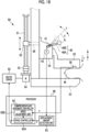
- the fifth embodiment is different from the first embodiment in the functional configuration of the processor 60 and in that a pressure sensor is provided on the compression plate 33.
- Fig. 18 shows a configuration of the mammography apparatus according to the fifth embodiment.
- the processor 60 includes the displacement amount detection unit 63 and the compression plate movement controller 62.
- the compression plate movement controller 62 includes the speed controller 62A and the speed adjustment unit 62B.
- the compression plate 33 is provided with a pressure sensor 58 that detects a pressure P received from the breast M interposed between the imaging table 23 and the compression plate 33.
- the pressure sensor 58 for example, a piezoelectric element is used.
- the pressure sensor 58 is an example of a "pressure detection unit" according to the technology of the present disclosure. Note that the pressure sensor 58 may be provided on the imaging table 23.
- the displacement amount detection unit 63 has the same function as the displacement amount detection unit 63 described in the second embodiment.
- the displacement amount detection unit 63 detects the angle ⁇ of the operation portion 40.
- the speed adjustment unit 62B adjusts the speed V based on the pressure P detected by the pressure sensor 58. For example, the speed adjustment unit 62B adjusts the speed V by multiplying the speed V by a coefficient that is inversely proportional to the magnitude of the pressure P. That is, the speed adjustment unit 62B performs adjustment to set the speed V to be slower as the pressure P is larger.
- the speed controller 62A controls the motor driver 55 such that the compression plate 33 is moved at the speed V adjusted by the speed adjustment unit 62B.
- the rate of change in speed which is a ratio of the change amount of the movement speed of the compression plate 33 to a unit displacement amount of the operation portion 40, is smaller as the pressure P is larger.
- Fig. 19 shows a relationship between the rate of change in speed and the pressure P.
- the relationship between the speed V and the angle ⁇ is a proportional relationship
- an inclination corresponding to the rate of change in speed is changed in response to the pressure P.
- the inclination is smaller as the pressure P is larger.
- the angle ⁇ of the operation portion 40 is fixed, the speed V is slower as the pressure P is larger.
- Steps S70 to S74 shown in Fig. 20 are the same as steps S10 to S14 shown in Fig. 4 , and thus the description thereof will be omitted.
- the compression plate movement controller 62 acquires the angle ⁇ as the displacement amount detected by the displacement amount detection unit 63 (step S75).
- the speed controller 62A obtains the speed V based on the angle ⁇ acquired by the compression plate movement controller 62 (step S76).
- the compression plate movement controller 62 acquires the pressure P detected by the pressure sensor 58 (step S77).
- the speed adjustment unit 62B adjusts the speed V based on the pressure P acquired by the compression plate movement controller 62 (step S78).
- the speed controller 62A controls the drive mechanism 50 such that the compression plate 33 is moved at the adjusted speed V (step S79).
- the compression plate movement controller 62 determines whether or not the operation of the operation portion 40 is terminated (step S80). In a case in which it is determined that the operation of the operation portion 40 is not terminated (step S80: NO), the compression plate movement controller 62 returns the process to step S75. In a case in which it is determined that the operation of the operation portion 40 is terminated (step S80: YES), the compression plate movement controller 62 terminates the process.
- Fig. 21 describes an action of the mammography apparatus according to the fifth embodiment.
- Fig. 21 shows the speed V of the compression plate 33 in a case in which the angle ⁇ of the operation portion 40 is the same and the pressure P is different. Even in a case in which the angle ⁇ is the same, in a case in which the pressure P is relatively low (pressure P 1 ), the speed V is high (speed V 1 ), and in a case in which the pressure P is relatively high (pressure P 2 ), the speed V is slow (speed V 2 ).
- the movement speed of the compression plate 33 is slower as the pressure of the breast M compressed by the compression plate 33 is larger, so that the safety of the apparatus is improved.
- Fig. 22 is a flowchart describing a movement control of the compression plate 33 according to a modification example of the fifth embodiment.
- the flowchart shown in Fig. 22 is different from the flowchart shown in Fig. 20 in that steps S90 and S91 are added.
- step S90 the compression plate movement controller 62 determines whether or not the pressure P detected by the pressure sensor 58 is equal to or larger than a preset threshold value. In a case in which it is determined that the pressure P is not equal to or larger than the threshold value (step S90: NO), the compression plate movement controller 62 shifts the process to step S78. On the other hand, in a case in which it is determined that the pressure P is equal to or larger than the threshold value, the compression plate movement controller 62 stops the movement of the compression plate 33 (step S91). Thereafter, the compression plate movement controller 62 shifts the process to step S80.
- the movement of the compression plate 33 is stopped in a case in which the pressure P is equal to or larger than the threshold value, and the height of the compression plate 33 is not changed, so that the safety is further improved.
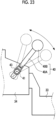
- Fig. 23 shows the operation portion 40 according to a first modification example.
- a coil spring 43 is attached to the rotation shaft 41 of the operation portion 40.
- the coil spring 43 is a biasing member that biases the operation portion 40 in a direction toward the neutral position shown by the solid line. Therefore, in a case in which the operation portion 40 is not operated, a posture of the operation portion 40 is maintained in the neutral position by the coil spring 43.
- the coil spring 43 increases a load for operating the operation portion 40. That is, the coil spring 43 functions as a load increasing unit for operating the operation portion 40.
- the load is larger as the displacement amount of the operation portion 40 is larger.
- Fig. 24 describes an action of the load increasing unit. As shown in Fig. 24 , in a case in which the operator manually displaces the operation portion 40 in the downward direction, the load increasing unit generates the load in a direction of returning the operation portion 40 to the neutral position. In a case in which the hand is released from the operation portion 40, the operation portion 40 is returned to the neutral position.
- the operation portion 40 By biasing the operation portion 40 to the neutral position, the operation portion 40 can be easily displaced in the vertical direction with the neutral position as a reference. In addition, the operator can intuitively recognize the displacement amount of the operation portion 40 depending on the magnitude of the load.
- a coil spring is used as the load increasing unit, but the load increasing unit is not limited to the coil spring, and various springs can be used.
- the load increasing unit is not limited to the spring, and a gear or the like may be used.
- a frictional force generation mechanism in which an electric actuator and a friction plate are combined may be used. The frictional force generation mechanism increases the frictional force in a direction opposite to the operation direction of the operation portion 40 in response to the displacement amount of the operation portion 40, for example. It is needless to say that in a case in which the spring is used as in the present example, a configuration is simple as compared with a case in which such a frictional force generation mechanism is used.
- Figs. 25 and 26 show an operation portion 70 according to a second modification example.
- the operation portion 70 includes a main shaft portion 71 extending from the base end side to the free end side, and a protruding portion 72 provided at the free end of the main shaft portion 71.
- the protruding portion 72 includes a first protruding portion 72A and a second protruding portion 72B.
- the first protruding portion 72A and the second protruding portion 72B are integrally formed.
- the protruding portion 72 intersects an axis A of the main shaft portion 71 and is curved in a convex shape toward the base end side of the main shaft portion 71.
- the first protruding portion 72A protrudes to a lower side with the axis A of the main shaft portion 71 as a reference.
- the second protruding portion 72B protrudes to an upper side with the axis A of the main shaft portion 71 as a reference.
- the axis A represents an axial direction of the main shaft portion 71.
- Fig. 27 shows an aspect in which the operator displaces the operation portion 70 in the downward direction.
- the operator can rotate the operation portion 70 in a direction in which the compression plate 33 is lowered by pressing the first protruding portion 72A in the downward direction, for example.
- the operator can also rotate the operation portion 70 in the direction in which the compression plate 33 is lowered by pressing the second protruding portion 72B in the downward direction.
- Fig. 28 shows an aspect in which the operator displaces the operation portion 70 in the upward direction.
- the operator can rotate the operation portion 70 in a direction in which the compression plate 33 is raised by pressing the second protruding portion 72B to the base end side of the main shaft portion 71.
- the operator can also rotate the operation portion 70 in the direction in which the compression plate 33 raised by pressing the first protruding portion 72A in the upward direction.
- Figs. 29 and 30 show an operation portion 70A according to a third modification example.
- the operation portion 70A includes the main shaft portion 71 extending from the base end side to the free end side, and the protruding portion 72 provided at the free end of the main shaft portion 71.
- the protruding portion 72 has a hook shape that is curved in a convex toward the body portion 24 (see Fig. 3 ) side of the mammography apparatus 10 (that is, the base end side of the main shaft portion 71), and is joined to the main shaft portion 71.
- the protruding portion 72 is provided on the upper side of the main shaft portion 71 with the axis A as a reference.
- the operator can rotate the operation portion 70A in the direction in which the compression plate 33 is lowered by pressing a lower part of the protruding portion 72 in the downward direction, for example.
- the operator can rotate the operation portion 70A in the direction in which the compression plate 33 is raised by pressing an upper part of the protruding portion 72 to the base end side of the main shaft portion 71, for example.
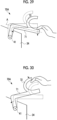
- Figs. 31 and 32 show an operation portion 70B according to a fourth modification example.
- the operation portion 70B includes the main shaft portion 71 extending from the base end side to the free end side, and the protruding portion 72 provided at the free end of the main shaft portion 71.
- the protruding portion 72 has a ring shape.
- the protruding portion 72 has an elliptical shape in which a long axis is parallel to the axis A of the main shaft portion 71, for example.
- the protruding portion 72 is provided on the upper side of the main shaft portion 71 with the axis A as a reference.
- the operator can rotate the operation portion 70B in the direction in which the compression plate 33 is lowered by pressing the lower part of the protruding portion 72 in the downward direction, for example.
- the operator can rotate the operation portion 70B in the direction in which the compression plate 33 is raised by pressing the upper part of the protruding portion 72 to the base end side of the main shaft portion 71, for example.
- the protruding portion 72 is provided on the upper side of the main shaft portion 71 with the axis A as a reference, but may be provided on the lower side with the axis A as a reference.
- the operation portion rotates in a first direction about the fulcrum.
- the operator disposes the hand from the free end side to the upper side of the main shaft portion 71 and presses the protruding portion 72 that protrudes to the upper side of the main shaft portion 71 to the base end side it is possible to rotate the protruding portion 72 about the fulcrum.
- the operator can generate rotation moment with respect to the operation portion in a direction opposite to that of a case in which the operation portion is pressed in the downward direction from the upper side without changing a position of the hand disposed on the upper side of the main shaft portion.
- the same effect can be obtained even in a case in which the protruding portion 72 is provided on the lower side of the main shaft portion 71 depending on the positional relationship with the fulcrum.
- the operation portion is configured by only the main shaft portion 71 without providing the protruding portion 72.
- the operator in a case in which the operation portion rotates in the first direction, the operator can dispose the hand on the upper side of the main shaft portion 71 and press the upper side of the main shaft portion 71 in the downward direction to rotate the operation portion in the first direction.
- the operation portion rotates in the second direction
- the operator in a case in which the operation portion rotates in the second direction, the operator can dispose the hand on the lower side of the main shaft portion 71 and press the lower side of the main shaft portion 71 in the upward direction to rotate the operation portion in the second direction.
- the operator intends to change the rotation direction of the operation portion, it is necessary to change the position of the hand disposed on one of the upper side or the lower side of the main shaft portion 71.
- the protruding portion 72 on the main shaft portion 71 as described above, even in a case in which the operator cannot grip the operation portion 70 from both sides of the upper side and the lower side, the operator can rotate the operation portion 70 any one direction of the first direction or the second direction only by the pressing operation without changing the position of the hand disposed one of the upper side or the lower side of the main shaft portion 71 to the opposite side.
- the protruding portion 72 on the main shaft portion 71 the operability of the operation portion 70 is improved.
- the effect of improving the operability of the operation portion 70 obtained by providing the protruding portion 72 on the main shaft portion 71 is significantly effective for the operator of the mammography apparatus 10 of which the movement of the hand is restricted. Further, the operation portion 70 is displaced along the vertical direction, which is the movement direction of the compression plate 33. In such an operation portion 70, it is significantly effective to improve the operability in the two directions of the upward direction and the downward direction by providing the protruding portion 72.
- the operation portion is provided on the movable portion. Therefore, the operation portion is moved together with the movable portion. An action and an effect of providing the operation portion on the movable portion will be described.
- the operation portion 40 is raised together with the movable portion 34.
- the movable portion 34 continues to be raised while the operator grips the operation portion 40 by the hand, there is a possibility that the hand comes into contact with the radiation source housing portion 22 provided above the body portion 24, and the hand is interposed between the operation portion 40 and the radiation source housing portion 22.
- the safety is improved as well as the operability of the compression plate 33 is improved.
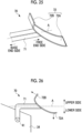
- the operation portion is provided on the movable portion, but in an example not forming part of the present invention the operation portion may be provided in a place other than the movable portion.
- Fig. 34 shows an example in which the operation portion 40 is provided on the body portion 24 of the arm 21 as a support portion.
- the operation portion 40 includes the main shaft portion 40A and the grip portion 40B.
- the main shaft portion 40A is bent in an L shape, and the base end side is rotatably connected to a side surface of the body portion 24.
- the free end side of the main shaft portion 40A stretches toward the side of the subject who places the breast M on the imaging table 23.
- the operation portion 40 is provided on a left side of the body portion 24 as viewed from a front side of the mammography apparatus 10, but the operation portion 40 may be provided on a right side of the body portion 24 or may be provided on both the right and left sides.
- the operation portion need only be a cantilever type lever having one end, which is the free end, and at least the free end need only be displaced along the movement direction of the compression plate.
- the displacement of the free end and the movement of the compression plate do not necessarily have to be in the same direction, and a form may be adopted in which the free end rotates and the compression plate is moved in a linear direction as described above.
- the operation portion does not rotate around the base end and is displaced in the linear direction in the vertical direction.
- the displacement direction of the operation portion completely coincides with the movement direction of the compression plate.
- the displacement amount detected by the displacement amount detection unit 63 described above corresponds to a slide movement amount, not the angle.
- the displacement speed detected by the displacement speed detection unit 65 corresponds to the speed, not the angular speed.
- a form of the lever has been described as an example of the operation portion, for example, a slide type switch can be used as the operation portion. In this case, the switch need only be disposed such that a sliding direction of the switch and the movement direction of the compression plate coincide with each other.
- the stretching direction of the operation portion has been described with an example of the anteroposterior direction (corresponding to the depth direction) of the mammography apparatus 10, a form may be adopted in which the stretching direction stretches in the width direction of the mammography apparatus 10.
- the lateral direction is a direction that intersects (for example, orthogonal to) the anteroposterior direction and the vertical direction.
- the first operation portion and the second operation portion are provided on, for example, a right side surface and a left side surface of the movable portion 34, respectively.
- the drive mechanism 50 is configured by the actuator using the rod screw, but it can also be configured by a belt type actuator. Further, a mechanical manual type movement mechanism can be used instead of the drive mechanism 50.
- the belt type actuator and the manual type movement mechanism are known, for example, in JP2010-179030A .
- processors described above include the CPU, which is a general-purpose processor that functions by executing a software (program), as well as a processor such as a field programmable gate array (FPGA) of which a circuit configuration can be changed after manufacturing.
- the FPGA includes a dedicated electric circuit, which is a processor having a circuit configuration specially designed for executing a specific process such as a programmable logic device (PLD) or an application specific integrated circuit (ASIC).
- PLD programmable logic device
- ASIC application specific integrated circuit
- the controller may be configured by one of these various processors or a combination of two or more processors of the same type or different types (for example, a combination of a plurality of the FPGAs, or a combination of the CPU and the FPGA).
- a plurality of the controllers may be configured by one processor.
- the plurality of controllers are configured by one processor.
- a computer such as a client computer or a server
- one processor is configured by a combination of one or more CPUs and software, and the processor functions as the plurality of controllers.
- a system on chip SOC
- the processor that realizes the functions of the entire system including the plurality of controllers by one IC chip is used.
- the controller can be configured by one or more of the various processors described above as the hardware structure.
Landscapes
- Health & Medical Sciences (AREA)
- Life Sciences & Earth Sciences (AREA)
- Medical Informatics (AREA)
- Engineering & Computer Science (AREA)
- Radiology & Medical Imaging (AREA)
- Molecular Biology (AREA)
- Biophysics (AREA)
- Nuclear Medicine, Radiotherapy & Molecular Imaging (AREA)
- Optics & Photonics (AREA)
- Pathology (AREA)
- Physics & Mathematics (AREA)
- Biomedical Technology (AREA)
- Heart & Thoracic Surgery (AREA)
- High Energy & Nuclear Physics (AREA)
- Surgery (AREA)
- Animal Behavior & Ethology (AREA)
- General Health & Medical Sciences (AREA)
- Public Health (AREA)
- Veterinary Medicine (AREA)
- Dentistry (AREA)
- Oral & Maxillofacial Surgery (AREA)
- Apparatus For Radiation Diagnosis (AREA)
Description
- The technology of the present disclosure relates to a mammography apparatus.
- A mammography apparatus is known that irradiates a breast of a subject with radiation and captures a radiation image of the breast. The mammography apparatus is provided with an imaging table on which the breast is placed and a compression plate which is disposed to face the imaging table and compresses the breast. The compression plate can be raised and lowered in a vertical direction with respect to the imaging table, and the breast is compressed by lowering the compression plate toward the imaging table. As an operation portion operated to raise and lower the compression plate, a button operation portion, a pedal operation portion, a rotation operation portion, and the like are known. The button operation portion and the pedal operation portion have two buttons or two foot pedals corresponding to a raising instruction and a lowering instruction, and are operated by a pressing operation of the button or a depressing operation of the pedal.
- The rotation operation portion includes a rotation knob, a jog dial, or the like. The rotation operation portion can rotate in two rotation directions, a clockwise direction and a counterclockwise direction, and the two rotation directions are assigned to the raising instruction or the lowering instruction, respectively. A mammography apparatus disclosed in
JP2004-57833A
DocumentUS 2014/348291 A1 provides an X-ray imaging apparatus including an X-ray source to emit an X-ray onto a breast, a detector assembly configured to detect the X-ray transmitted through the breast, a compression paddle configured to compress the breast positioned on the detector assembly, a paddle manipulator configured to control the compression paddle according to a command, a degree-of-compression sensor configured to measure a degree of compression to which the breast is compressed by the compression paddle, and a pressure controller configured to supply a pressure corresponding to the measured degree of compression of the breast to the paddle manipulator. - In each of the operation portions described above, the operation direction is not along a movement direction of the compression plate in the vertical direction. For example, the operation directions of the pressing operation of the button or the depressing operation of the pedal, and the rotation operation of the rotation knob or the jog dial are all significantly different from the vertical direction, which is the movement direction of the raising and lowering operation of the compression plate. In a case in which the operation direction of the operation portion is not along the movement direction of the compression plate as described above, it is difficult to understand a correspondence between the operation direction of the operation portion and the movement direction of the compression plate. In a case in which the correspondence is difficult to understand, it is necessary for an operator to confirm the correspondence for each operation, such as which of the two buttons is pressed to raise or lower the compression plate or which way to turn the rotation knob to raise or lower the compression plate, and thus there is a problem of poor operability, such as the need to move the compression plate slightly on a trial basis to confirm the movement direction.
DocumentJP H04 64346 A JP H04 64346 A - The present invention is to provide a mammography apparatus having better operability of a compression plate than the related art. The present invention relates to a mammography apparatus with the features of
claim 1. - The mammography apparatus according to the present invention comprises an imaging table on which a breast of a subject is placed, a compression plate that compresses the breast, the compression plate being disposed to face the imaging table and being movable in a vertical direction with respect to the imaging table, and an operation portion that is operated to move the compression plate, the operation portion being provided separately from the compression plate and being displaced along a movement direction of the compression plate.
- According to the invention, the mammography apparatus further comprises a support portion that is connected to and moves together with the compression plate to be movable with respect to the imaging table, in which the operation portion is provided on the support portion.
- According to a non-claimed example, the mammography apparatus may comprise a support portion that supports the compression plate to be movable with respect to the imaging table, and a movable portion that is disposed between the compression plate and the support portion and is moved in the vertical direction together with the compression plate, in which the operation portion is provided on the support portion.
- According to the invention, the mammography apparatus further comprises an actuator that drives the compression plate, in which the actuator is activated in response to an operation of the operation portion, and the compression plate is moved by driving force generated by the actuator.
- It is preferable that the mammography apparatus further comprises a processor that controls the actuator to change a movement speed of the compression plate.
- It is preferable that the mammography apparatus further comprises a displacement amount detection unit that detects a displacement amount of the operation portion, in which the processor changes the movement speed of the compression plate based on the displacement amount detected by the displacement amount detection unit.
- It is preferable that the mammography apparatus further comprises a height detection unit that detects a height of the compression plate with respect to the imaging table, in which the processor changes the movement speed of the compression plate in response to the height of the compression plate.
- It is preferable that the processor sets an initial speed of the compression plate in a case in which the compression plate is raised from a state in which the compression plate is positioned at a relatively low position to be faster than an initial speed of the compression plate in a case in which the compression plate is raised from a state in which the compression plate is positioned at a relatively high position.
- It is preferable that the processor sets an initial speed of the compression plate in a case in which the compression plate is lowered from a state in which the compression plate is positioned at a relatively high position to be faster than an initial speed of the compression plate in a case in which the compression plate is lowered from a state in which the compression plate is positioned at a relatively low position.
- It is preferable that the mammography apparatus further comprises a displacement speed detection unit that detects a displacement speed of the operation portion, in which the processor sets the movement speed of the compression plate to be faster as the displacement speed of the operation portion is faster.
- It is preferable that the mammography apparatus further comprises a pressure detection unit that detects a pressure received by the compression plate from the breast.
- It is preferable that the processor sets a rate of change in speed, which is a ratio of a change amount of the movement speed of the compression plate to a unit displacement amount of the operation portion, to be smaller as the pressure is larger.
- It is preferable that the processor stops movement of the compression plate in a case in which the pressure detected by the pressure detection unit is equal to or larger than a preset threshold value.
- It is preferable that the mammography apparatus further comprises a load increasing unit that increases a load for operating the operation portion as a displacement amount of the operation portion is larger.
- According to the invention, the operation portion is a cantilever type lever having one end, which is a free end, and at least the free end is displaced along the movement direction of the compression plate.
- It is preferable that assuming that a direction of a position of the subject who places the breast on the imaging table is anterior and an opposite direction thereof is posterior, the operation portion stretches in an anteroposterior direction or a lateral direction.
- It is preferable that the operation portion rotates about a fulcrum provided on a base end side.
- It is preferable that the operation portion includes a main shaft portion that extends from the base end side to a free end side, and a protruding portion that is provided on the main shaft portion and protrudes to at least one of a lower side or an upper side with an axial direction of the main shaft portion as a reference.
- It is preferable that the protruding portion includes a first protruding portion that protrudes to the lower side of the main shaft portion, and a second protruding portion that protrudes to the upper side of the main shaft portion.
- It is preferable that the protruding portion has a hook shape or a ring shape.
- According to the technology of the present invention, it is possible to provide a mammography apparatus having better operability of the compression plate than the related art.
-
-
Fig. 1 is a perspective view showing an example of an overall configuration of a mammography apparatus according to a first embodiment. -
Fig. 2 is a partially enlarged view of the mammography apparatus. -
Fig. 3 is a view showing an example of configurations of a drive mechanism of a compression plate and a processor. -
Fig. 4 is a flowchart showing an example of a movement control of the compression plate. -
Fig. 5 is a view showing a configuration of a mammography apparatus according to a second embodiment. -
Fig. 6 is a graph showing an example of a relationship between an angle and a speed. -
Fig. 7 is a graph showing another example of the relationship between the angle and the speed. -
Fig. 8 is a flowchart showing an example of a movement control according to the second embodiment. -
Fig. 9 is a view describing an action of the mammography apparatus according to the second embodiment. -
Fig. 10 is a view showing a configuration of a mammography apparatus according to a third embodiment. -
Fig. 11 is a graph showing an example of a relationship between a height and an initial speed. -
Fig. 12 is a flowchart showing an example of a movement control according to the third embodiment. -
Fig. 13 is a view describing an action of the mammography apparatus according to the third embodiment. -
Fig. 14 is a view describing the action of the mammography apparatus according to the third embodiment. -
Fig. 15 is a view showing a configuration of a mammography apparatus according to a fourth embodiment. -
Fig. 16 is a flowchart showing an example of a movement control according to the fourth embodiment. -
Fig. 17 is a view describing an action of the mammography apparatus according to the fourth embodiment. -
Fig. 18 is a view showing a configuration of a mammography apparatus according to a fifth embodiment. -
Fig. 19 is a graph showing a relationship between a rate of change in speed and a pressure. -
Fig. 20 is a flowchart showing an example of a movement control according to the fifth embodiment. -
Fig. 21 is a view describing an action of the mammography apparatus according to the fifth embodiment. -
Fig. 22 is a flowchart describing a movement control according to a modification example of the fifth embodiment. -
Fig. 23 is a view showing an operation portion according to a first modification example. -
Fig. 24 is a view describing an action of a load increasing unit. -
Fig. 25 is a perspective view showing an operation portion according to a second modification example. -
Fig. 26 is a side view showing the operation portion according to the second modification example. -
Fig. 27 is a view showing an aspect in which the operation portion according to the second modification example is displaced in a downward direction. -
Fig. 28 is a view showing an aspect in which the operation portion according to the second modification example is displaced in an upward direction. -
Fig. 29 is a view showing an aspect in which an operation portion according to a third modification example is displaced in the downward direction. -
Fig. 30 is a view showing an aspect in which the operation portion according to the third modification example is displaced in the upward direction. -
Fig. 31 is a view showing an aspect in which an operation portion according to a fourth modification example is displaced in the downward direction. -
Fig. 32 is a view showing an aspect in which the operation portion according to the fourth modification example is displaced in the upward direction. -
Fig. 33 is a view describing an action and an effect of providing the operation portion on a movable portion. -
Fig. 34 is a partially enlarged view of the mammography apparatus in which the operation portion is provided on a support portion. -
Fig. 1 shows an example of an overall configuration of a mammography apparatus according to a first embodiment. Amammography apparatus 10 uses a breast M of a subject (seeFig. 3 ) as an object. Themammography apparatus 10 is a radiography apparatus that irradiates the breast M with radiation (for example, X-rays or γ-rays) and captures a radiation image of the breast M. - The
mammography apparatus 10 comprises anapparatus body 11 and acontrol device 12. Theapparatus body 11 is installed in a radiography room of a medical facility, for example. Thecontrol device 12 is installed in a control room adjacent to the radiography room, for example. Thecontrol device 12 is a desktop-type personal computer, for example. Thecontrol device 12 is communicably connected to an image database server (not shown) via a network (not shown) such as a local area network (LAN). - The
apparatus body 11 includes astand 20 and anarm 21. Thestand 20 is configured by aseat 20A installed on a floor of the radiography room and asupport column 20B extending in a height direction from theseat 20A. Thearm 21 has a substantially C-shape as viewed from the side, and is connected to thesupport column 20B. Since thearm 21 is movable in the height direction with respect to thesupport column 20B, a height thereof can be adjusted in response to a height of the subject. In addition, thearm 21 can rotate around a rotation shaft perpendicular to thesupport column 20B. - The
arm 21 is configured by a radiationsource housing portion 22, an imaging table 23, and abody portion 24. Aradiation source 25 is housed in the radiationsource housing portion 22. The breast M of the subject is placed on the imaging table 23. Aradiation detector 26 is housed in the imaging table 23. Thebody portion 24 integrally connects the radiationsource housing portion 22 and the imaging table 23. Thebody portion 24 holds the radiationsource housing portion 22 and the imaging table 23 at facing positions.Handrails 27 held by the subject by the hands are provided on the both sides of thebody portion 24. - The
radiation source 25 irradiates the breast M placed on the imaging table 23 with the radiation. The radiation emitted from theradiation source 25 is transmitted through acompression plate 33 and then incident on the breast M. Theradiation detector 26 detects the radiation transmitted through the breast M and outputs the radiation image. Theradiation detector 26 is called a flat panel detector (FPD). Theradiation detector 26 may include a scintillator that converts the radiation into visible light, and may be an indirect conversion type that converts the visible light emitted by the scintillator into an electric signal, or a direct conversion type that directly converts the radiation into an electric signal. - An
irradiation field limiter 31 is provided between the radiationsource housing portion 22 and the imaging table 23. Theirradiation field limiter 31 is also called a collimator, and defines an irradiation field of the radiation to the imaging table 23. - A
face guard 32 is attached to the radiationsource housing portion 22. Theface guard 32 is made or coated with a material through which the radiation is not transmitted, and protects a face of the subject from the radiation. - The
compression plate 33, which interposes and compresses the breast M with the imaging table 23, is provided between the imaging table 23 and theirradiation field limiter 31. Thecompression plate 33 is made of a material through which the radiation is transmitted. Thecompression plate 33 is disposed at a position facing the imaging table 23. In the present embodiment, thecompression plate 33 has a box shape with an open upper surface side. Thecompression plate 33 may have another shape, such as a flat plate shape. - The
body portion 24 of thearm 21 supports thecompression plate 33 to be movable with respect to the imaging table 23. Thebody portion 24 is an example of a "support portion" according to the technology of the present disclosure. In addition, amovable portion 34 is disposed between thecompression plate 33 and thebody portion 24. Themovable portion 34 is held by arail 28 provided on thebody portion 24 to be movable slidingly. Therail 28 stretches in a vertical direction. - The
compression plate 33 is attached to themovable portion 34. Themovable portion 34 is moved in the vertical direction together with thecompression plate 33 by a drive mechanism, which will be described below. Functionally, the vertical direction is a direction in which thecompression plate 33 is moved toward the imaging table 23 (downward direction) and a direction in which thecompression plate 33 is separated from the imaging table 23 (upward direction). As described above, thecompression plate 33 is configured to be movable with respect to the imaging table 23. -
Fig. 2 is a partially enlarged view of themammography apparatus 10. As shown inFig. 2 , themammography apparatus 10 is provided with anoperation portion 40 that moves thecompression plate 33 in the vertical direction. Theoperation portion 40 is provided separately from thecompression plate 33, and is displaced along a movement direction of thecompression plate 33. In the present embodiment, theoperation portion 40 is provided on themovable portion 34. - The
operation portion 40 is operated in a case in which an operator, such as a radiologist, compresses the breast with respect to the imaging table 23 with thecompression plate 33 to perform positioning of the breast M during radiography. In addition, theoperation portion 40 is operated in a case in which the operator releases the compression of the breast M by thecompression plate 33 after the radiography is terminated. - As shown in
Fig. 3 , theoperation portion 40 is a cantilever type lever having one end, which is a free end, and the free end is displaced along the movement direction of thecompression plate 33. In the present embodiment, theoperation portion 40 is configured by a rod-shapedmain shaft portion 40A and a spherical-shapedgrip portion 40B. Thegrip portion 40B is attached to one end (that is, free end) of themain shaft portion 40A. Arotation shaft 41 is provided at the other end (that is, base end) of themain shaft portion 40A. Therotation shaft 41 is disposed inside themovable portion 34. - The
operation portion 40 is attached to themovable portion 34 such that themain shaft portion 40A stretches toward a side of the subject who places the breast M on the imaging table 23. In the present embodiment, themain shaft portion 40A obliquely stretches in the upward direction toward the side of the subject. That is, assuming that a direction of a position of the subject who places the breast on the imaging table 23 is anterior and an opposite direction thereof is posterior, theoperation portion 40 having a lever shape stretches in an anteroposterior direction. In themammography apparatus 10, assuming that astand 20 side is posterior and a direction in which the imaging table 23 protrudes is anterior, the anteroposterior direction is, in other words, a depth direction of themammography apparatus 10, and theoperation portion 40 stretches in the depth direction of themammography apparatus 10. Here, the anteroposterior direction, which is a stretching direction of theoperation portion 40, is a concept including a case other than a case of being parallel to the floor (horizontal plane) as in the present example, and does not include a width direction and a perpendicular direction of themammography apparatus 10. Specifically, in a case of being defined by an angle with the horizontal plane as a reference, the stretching direction of theoperation portion 40 at a neutral position (position indicated by a solid line inFig. 3 ) in a state of not being operated is about 60° or less with respect to the horizontal plane, preferably 45° or less as in the present example. - The
operation portion 40 rotates with therotation shaft 41 provided on a base end side as a fulcrum. Thegrip portion 40B is displaced in a direction along the movement direction of thecompression plate 33, that is, in the vertical direction. The operator can displace thegrip portion 40B in the vertical direction in a state of gripping thegrip portion 40B. In a case in which thegrip portion 40B is displaced in the downward direction, thecompression plate 33 is moved (that is, lowered) toward the imaging table 23. In a case in which thegrip portion 40B is displaced in the upward direction, thecompression plate 33 moves (that is, raised) in a direction separated from the imaging table 23. - Further,
Fig. 3 shows an example of configurations of the drive mechanism of thecompression plate 33 and a processor that controls movement of thecompression plate 33. Adrive mechanism 50 shown inFig. 3 is a so-called electric linear actuator. Thedrive mechanism 50 is provided, for example, inside thebody portion 24 and is activated by an operation of theoperation portion 40. - The
drive mechanism 50 includes arod screw 51, anut 52, acoupling 53, amotor 54, and amotor driver 55. Therod screw 51 extends in the vertical direction along the rail 28 (seeFig. 2 ). Therod screw 51 is a trapezoidal screw, for example. Thenut 52 is screwed with therod screw 51. Themovable portion 34 is connected to thenut 52 via aconnection portion 56. Themovable portion 34 is moved in the vertical direction together with thenut 52 by rotation of therod screw 51. - The
motor 54 is connected to therod screw 51 via thecoupling 53. Themotor 54 is driven by themotor driver 55 and rotates therod screw 51 via thecoupling 53. A rotation direction of therod screw 51 corresponds to the movement direction of themovable portion 34. For example, in a case in which therod screw 51 rotates clockwise, themovable portion 34 is lowered, and in a case in which therod screw 51 rotates counterclockwise, themovable portion 34 is raised. In addition, a rotation speed of therod screw 51 corresponds to a movement speed of themovable portion 34. - As described above, the
compression plate 33 is moved together with themovable portion 34 by driving force generated by thedrive mechanism 50 as the actuator. - A
processor 60 is configured by, for example, a central processing unit (CPU), a memory, and the like. Theprocessor 60 realizes various functions by executing a process by the CPU based on a program stored in the memory. Theprocessor 60 is provided, for example, inside thebody portion 24. - In the present embodiment, the
processor 60 includes a displacementdirection detection unit 61 and a compressionplate movement controller 62. The displacementdirection detection unit 61 detects a displacement direction of theoperation portion 40 based on a detection signal output from apotentiometer 42 as an angle detection sensor connected to therotation shaft 41 of theoperation portion 40. Thepotentiometer 42 is provided inside themovable portion 34, and outputs the detection signal in response to an angle of theoperation portion 40. Note that it is also possible to use an encoder as the angle detection sensor instead of thepotentiometer 42. - In
Fig. 3 , a state in which theoperation portion 40 is positioned at the neutral position is shown by the solid line. For example, the displacementdirection detection unit 61 detects a case in which thegrip portion 40B of theoperation portion 40 is displaced in the downward direction from the neutral position as "displacement in a positive direction" and detects a case in which thegrip portion 40B of theoperation portion 40 is displaced in the upward direction from the neutral position as "displacement in a negative direction", and detects whether the displacement direction is positive or negative. - The compression
plate movement controller 62 controls thedrive mechanism 50 based on the displacement direction detected by the displacementdirection detection unit 61. Specifically, the compressionplate movement controller 62 controls themotor driver 55 in response to the displacement direction detected by the displacementdirection detection unit 61 to change a rotation direction of themotor 54. In a case in which the displacement direction is the positive direction (that is, downward direction), the compressionplate movement controller 62 lowers thecompression plate 33 together with themovable portion 34 by rotating themotor 54 clockwise. In addition, in a case in which the displacement direction is the negative direction (that is, upward direction), the compressionplate movement controller 62 raises thecompression plate 33 together with themovable portion 34 by rotating themotor 54 counterclockwise. - Next, an example of a movement control of the
compression plate 33 by the compressionplate movement controller 62 will be described with reference to a flowchart shown inFig. 4 . First, the compressionplate movement controller 62 determines whether or not the operation of theoperation portion 40 is started (step S10). For example, the compressionplate movement controller 62 determines that the operation of theoperation portion 40 is started in a case in which theoperation portion 40 is displaced from the neutral position. - In a case in which it is determined that the operation of the
operation portion 40 is started (step S10: YES), the compressionplate movement controller 62 acquires the displacement direction detected by the displacement direction detection unit 61 (step S11). The compressionplate movement controller 62 determines whether or not the acquired displacement direction is the downward direction (step S12). In a case in which it is determined that the displacement direction is the downward direction (step S12: YES), the compressionplate movement controller 62 controls thedrive mechanism 50 to lower the compression plate 33 (step S13). On the other hand, in a case in which it is determined that the displacement direction is the upward direction (step S12: NO), the compressionplate movement controller 62 controls thedrive mechanism 50 to raise the compression plate 33 (step S14). - After executing step S13 or step S14, the compression
plate movement controller 62 determines whether or not the operation of theoperation portion 40 is terminated (step S15). For example, the compressionplate movement controller 62 determines that the operation of theoperation portion 40 is terminated in a case in which theoperation portion 40 is returned to the neutral position. In a case in which it is determined that the operation of theoperation portion 40 is not terminated (step S15: NO), the compressionplate movement controller 62 returns the process to step S11. - The compression
plate movement controller 62 repeats the processes of steps S11 to S15 until it is determined that the operation of theoperation portion 40 is terminated, and terminates the process in a case in which it is determined that the operation of theoperation portion 40 is terminated (step S15: YES). - In a case in which the
compression plate 33 is lowered to compress the breast M, the operator who operates theoperation portion 40 need only operate theoperation portion 40 in a direction in which thecompression plate 33 is lowered. On the contrary, in a case in which thecompression plate 33 is raised to release the compression of the breast M, the operator who operates theoperation portion 40 need only operate theoperation portion 40 in a direction in which thecompression plate 33 is raised. - As described above, in the present embodiment, the operation portion is displaced along the movement direction of the compression plate, and thus the operation direction of the operation portion and the movement direction of the compression plate are substantially the same. Therefore, the operator can intuitively operate the operation portion. That is, the mammography apparatus according to the present embodiment has better operability of the compression plate as compared with an apparatus in the related art in which the operation direction of the operation portion and the movement direction of the compression plate are significantly different. Therefore, according to the technology of the present disclosure, it is possible to provide the mammography apparatus having better operability of the compression plate than the related art.
- Next, a mammography apparatus according to a second embodiment will be described. The second embodiment is different from the first embodiment only in a functional configuration of the
processor 60. -
Fig. 5 shows a configuration of the mammography apparatus according to the second embodiment. As shown inFig. 5 , in the present embodiment, theprocessor 60 includes a displacementamount detection unit 63 and the compressionplate movement controller 62. In addition, the compressionplate movement controller 62 includes aspeed controller 62A. - The displacement
amount detection unit 63 detects an angle θ of theoperation portion 40 based on the detection signal output from thepotentiometer 42. InFig. 5 , the state in which theoperation portion 40 is positioned at the neutral position is shown by a broken line. The angle θ represents a rotation angle of theoperation portion 40 from the neutral position. For example, the angle θ has a "positive value" in a case in which thegrip portion 40B of theoperation portion 40 is displaced in the downward direction from the neutral position, and has a "negative value" in a case in which thegrip portion 40B of theoperation portion 40 is displaced in the upward direction from the neutral position. That is, the angle θ is a concept including the "displacement direction" described in the first embodiment. Note that the angle θ is an example of a "displacement amount" according to the technology of the present disclosure. - The
speed controller 62A obtains a speed V corresponding to the angle θ as the displacement amount detected by the displacementamount detection unit 63, and controls themotor driver 55 such that thecompression plate 33 is moved at the obtained speed V. For example, the speed V has a "positive value" in a case in which thecompression plate 33 is lowered, and has a "negative value" in a case in which thecompression plate 33 is raised. That is, the speed V is a concept including the "movement direction" described in the first embodiment. Thespeed controller 62A controls a rotation speed (including the rotation direction) of themotor 54 via themotor driver 55 to change the speed V at which thecompression plate 33 is moved. -
Fig. 6 shows an example of a relationship between the angle θ and the speed V. InFig. 6 , the speed V has a proportional relationship with the angle θ. Thespeed controller 62A obtains the speed V corresponding to the angle θ detected by the displacementamount detection unit 63 based on the relationship between the angle θ and the speed V shown inFig. 6 . Note that thespeed controller 62A may store the relationship between the angle θ and the speed V as a function to obtain the speed V based on the function. In addition, thespeed controller 62A may store the relationship between the angle θ and the speed V in the memory as a look up table (LUT), and obtain the speed V based on the LUT. - In a case in which the
speed controller 62A performs a speed control using the relationship between the angle θ and the speed V shown inFig. 6 , the speed V of thecompression plate 33 is changed in proportion to the displacement amount of theoperation portion 40. That is, a rate of change in the speed V of thecompression plate 33 with respect to a unit displacement amount of theoperation portion 40 is fixed. -
Fig. 7 shows another example of the relationship between the angle θ and the speed V. InFig. 7 , a relationship between the speed V and the angle θ is non-linear, and the rate of change in the speed V is larger as the angle θ is larger. The speed V is changed with respect to the angle θ at a rate of change such as an exponential function, for example. - In a case in which the
speed controller 62A performs a speed control using the relationship between the angle θ and the speed V shown inFig. 7 , the rate of change in the speed V of thecompression plate 33 is increased as the displacement amount of theoperation portion 40 is larger. - Next, an example of a movement control of the
compression plate 33 according to the present embodiment will be described with reference to a flowchart shown inFig. 8 . Steps S20 to S24 shown inFig. 8 are the same as steps S10 to S14 shown inFig. 4 , and thus the description thereof will be omitted. - After step S23 or step S24, the compression
plate movement controller 62 acquires the angle θ as the displacement amount detected by the displacement amount detection unit 63 (step S25). Thespeed controller 62A obtains the speed V based on the angle θ acquired by the compression plate movement controller 62 (step S26). Then, thespeed controller 62A controls thedrive mechanism 50 such that thecompression plate 33 is moved at the obtained speed V (step S27). - Thereafter, the compression
plate movement controller 62 determines whether or not the operation of theoperation portion 40 is terminated (step S28). In a case in which it is determined that the operation of theoperation portion 40 is not terminated (step S28: NO), the compressionplate movement controller 62 returns the process to step S25. In a case in which it is determined that the operation of theoperation portion 40 is terminated (step S28: YES), the compressionplate movement controller 62 terminates the process. -
Fig. 9 describes an action of the mammography apparatus according to the second embodiment.Fig. 9 shows the change in the speed V in a case in which the angle θ of theoperation portion 40 is increased. As shown inFig. 9 , in the present embodiment, in a case in which the angle θ of theoperation portion 40 is increased from θ1 to θ2, the speed V of thecompression plate 33 is increased from V1 to V2.Fig. 9 shows a case in which theoperation portion 40 is displaced in the downward direction, but the same applies to a case in which theoperation portion 40 is displaced in the upward direction. - In the present embodiment, the movement speed of the
compression plate 33 is faster as the displacement amount of theoperation portion 40 is larger, so that the operator can intuitively perform the operation. - Next, a mammography apparatus according to a third embodiment will be described. The third embodiment is different from the first embodiment in the functional configuration of the
processor 60 and in that anencoder 57 is connected to themotor 54. -
Fig. 10 shows a configuration of the mammography apparatus according to the third embodiment. As shown inFig. 10 , in the present embodiment, theprocessor 60 includes the displacementamount detection unit 63, aheight detection unit 64, and the compressionplate movement controller 62. In addition, the compressionplate movement controller 62 includes thespeed controller 62A and aspeed adjustment unit 62B. Further, in the present embodiment, theencoder 57 is connected to themotor 54. - The displacement
amount detection unit 63 and thespeed controller 62A have the same functions as the displacementamount detection unit 63 and thespeed controller 62A described in the second embodiment. The displacementamount detection unit 63 detects the angle θ of theoperation portion 40. Thespeed controller 62A obtains the speed V corresponding to the angle θ detected by the displacementamount detection unit 63, and controls themotor driver 55 such that thecompression plate 33 is moved at the obtained speed V. - The
encoder 57 converts a mechanical displacement amount of the rotation of themotor 54 into an electric signal and outputs the converted electric signal. Theheight detection unit 64 detects a height H of thecompression plate 33 with respect to the imaging table 23 based on the output signal output from theencoder 57. The height H refers to an interval between thecompression plate 33 and the imaging table 23. The height H of thecompression plate 33 with respect to the imaging table 23 is higher as the interval between thecompression plate 33 and the imaging table 23 is wider, and the height H of thecompression plate 33 with respect to the imaging table 23 is lower as the interval therebetween is narrower. - Specifically, the output signal of the
encoder 57 includes a pulse in response to the rotation of themotor 54. Theheight detection unit 64 counts the number of the pulses included in the output signal of theencoder 57, and converts the counted number of the pulses into a distance to obtain the height H. Note that it is also possible to use a potentiometer instead of theencoder 57. - The
speed adjustment unit 62B adjusts the speed V of thecompression plate 33 controlled by thespeed controller 62A. In the present embodiment, thespeed adjustment unit 62B adjusts an initial speed Vi of thecompression plate 33 in response to the height H detected by theheight detection unit 64 and the displacement direction of thecompression plate 33. The initial speed Vi is the movement speed immediately after the start of movement of thecompression plate 33, which is moved from a stationary state. After the start of movement of thecompression plate 33, during a certain period of time, thespeed adjustment unit 62B applies the initial speed Vi in response to the height H and the displacement direction of thecompression plate 33 instead of the speed V obtained by thespeed controller 62A. Note that the period of time during which the initial speed Vi is applied may be a fixed value, but may be the time from the start of movement of thecompression plate 33 to the time when a movement amount reaches a defined value. - The
speed adjustment unit 62B decides the initial speed Vi, for example, based on a relationship between the height H and the initial speed Vi shown inFig. 11 . Thespeed adjustment unit 62B obtains the displacement direction of thecompression plate 33 based on the angle θ as the displacement amount detected by the displacementamount detection unit 63. - In a case in which the displacement direction of the
compression plate 33 is the downward direction, thespeed adjustment unit 62B decides the initial speed Vi by using a first function F1. In addition, in a case in which the displacement direction of thecompression plate 33 is the upward direction, thespeed adjustment unit 62B decides the initial speed Vi by using a second function F2. In the first function F1, the initial speed Vi is faster as the height H is higher. On the contrary, in the second function F2, the initial speed Vi is faster as the height H is lower. In the present embodiment, the first function F1 and the second function F2 are linear functions, but the first function F1 and the second function F2 may be non-linear functions. In addition, thespeed adjustment unit 62B may store information representing the first function F1 and the second function F2 as the LUT in the memory, and decide the initial speed Vi based on the LUT. - Next, an example of a movement control of the
compression plate 33 according to the present embodiment will be described with reference to a flowchart shown inFig. 12 . Steps S30 to S34 shown inFig. 12 are the same as steps S10 to S14 shown inFig. 4 , and thus the description thereof will be omitted. - After step S33 or step S34, the compression
plate movement controller 62 acquires the height H detected by the height detection unit 64 (step S35). Thespeed adjustment unit 62B decides the initial speed Vi based on the height H acquired by the compression plate movement controller 62 (step S36). At this time, thespeed adjustment unit 62B selects one of the first function F1 or the second function F2 based on the displacement direction detected by the displacementamount detection unit 63, and uses the selected function to decide the initial speed Vi corresponding to the height H. - Next, the compression
plate movement controller 62 acquires the angle θ as the displacement amount detected by the displacement amount detection unit 63 (step S37). Thespeed controller 62A obtains the speed V based on the angle θ acquired by the compression plate movement controller 62 (step S38). Then, thespeed controller 62A controls thedrive mechanism 50 based on the initial speed Vi decided by thespeed adjustment unit 62B and the obtained speed V (step S39). At this time, thespeed controller 62A applies the initial speed Vi instead of the speed V for a certain period of time. - Thereafter, the compression
plate movement controller 62 determines whether or not the operation of theoperation portion 40 is terminated (step S40). In a case in which it is determined that the operation of theoperation portion 40 is not terminated (step S40: NO), the compressionplate movement controller 62 returns the process to step S37. In a case in which it is determined that the operation of theoperation portion 40 is terminated (step S40: YES), the compressionplate movement controller 62 terminates the process. - As described above, the acquisition of the height H (step S35) and the decision of the initial speed Vi (step S36) are executed only immediately after the start of the operation of the
operation portion 40. -
Figs. 13 and14 are views describing an action of the mammography apparatus according to the third embodiment.Fig. 13 shows the initial speed Vi in a case in which thecompression plate 33 is lowered from two different heights H. An initial speed Vi1d of thecompression plate 33 in a case in which thecompression plate 33 is lowered from a state in which thecompression plate 33 is positioned at a relatively high position (height H1) is faster than an initial speed Vi2d of thecompression plate 33 in a case in which thecompression plate 33 is lowered from a state in which thecompression plate 33 is positioned at a relatively low position (height H2). -
Fig. 14 shows the initial speed Vi in a case in which thecompression plate 33 is raised from two different heights H. An initial speed Vi2u of thecompression plate 33 in a case in which thecompression plate 33 is raised from a state in which thecompression plate 33 is positioned at a relatively low position (height H2) is faster than an initial speed Vi1u of thecompression plate 33 in a case in which thecompression plate 33 is raised from a state in which thecompression plate 33 is positioned at a relatively high position (height H1). - In the present embodiment, the initial speed Vi is decreased in a case in which the
compression plate 33 is moved from a position close to an upper limit or a lower limit of a movable range of thecompression plate 33, so that the safety of the apparatus is improved. - Next, a mammography apparatus according to a fourth embodiment will be described. The fourth embodiment is different from the first embodiment only in the functional configuration of the
processor 60. -
Fig. 15 shows a configuration of the mammography apparatus according to the fourth embodiment. As shown inFig. 15 , in the present embodiment, theprocessor 60 includes the displacementamount detection unit 63, a displacementspeed detection unit 65, and the compressionplate movement controller 62. In addition, the compressionplate movement controller 62 includes thespeed controller 62A and thespeed adjustment unit 62B. - The displacement
amount detection unit 63 has the same function as the displacementamount detection unit 63 described in the second embodiment. The displacementamount detection unit 63 detects the angle θ of theoperation portion 40. - The displacement
speed detection unit 65 detects a displacement speed ω of theoperation portion 40 by obtaining a rate of temporal change in the angle θ detected by the displacementamount detection unit 63. In the present embodiment, the displacement speed ω is an angular speed. - In the present embodiment, the
speed adjustment unit 62B adjusts the speed V based on the displacement speed ω detected by the displacementspeed detection unit 65. For example, thespeed adjustment unit 62B adjusts the speed V by multiplying the speed V by a coefficient proportional to the magnitude of the displacement speed ω. That is, thespeed adjustment unit 62B performs adjustment to set the speed V to be faster as the displacement speed ω is faster. In the present embodiment, thespeed controller 62A controls themotor driver 55 such that thecompression plate 33 is moved at the speed V adjusted by thespeed adjustment unit 62B. - Next, an example of a movement control of the
compression plate 33 according to the present embodiment will be described with reference to a flowchart shown inFig. 16 . Steps S50 to S54 shown inFig. 16 are the same as steps S10 to S14 shown inFig. 4 , and thus the description thereof will be omitted. - After step S53 or step S54, the compression
plate movement controller 62 acquires the angle θ as the displacement amount detected by the displacement amount detection unit 63 (step S55). Thespeed controller 62A obtains the speed V based on the angle θ acquired by the compression plate movement controller 62 (step S56). - Next, the compression
plate movement controller 62 acquires the displacement speed ω detected by the displacement speed detection unit 65 (step S57). Thespeed adjustment unit 62B adjusts the speed V based on the displacement speed ω acquired by the compression plate movement controller 62 (step S58). Then, thespeed controller 62A controls thedrive mechanism 50 such that thecompression plate 33 is moved at the adjusted speed V (step S59). - Thereafter, the compression
plate movement controller 62 determines whether or not the operation of theoperation portion 40 is terminated (step S60). In a case in which it is determined that the operation of theoperation portion 40 is not terminated (step S60: NO), the compressionplate movement controller 62 returns the process to step S55. In a case in which it is determined that the operation of theoperation portion 40 is terminated (step S60: YES), the compressionplate movement controller 62 terminates the process. -
Fig. 17 describes an action of the mammography apparatus according to the fourth embodiment.Fig. 17 shows the speed V of thecompression plate 33 in a case in which the angle θ of theoperation portion 40 is the same and the displacement speed ω is different. Even in a case in which the angle θ is the same, in a case in which the displacement speed ω is relatively slow (displacement speed ω1), the speed V is slow (speed V1), and in a case in which the displacement speed ω is relatively fast (displacement speed ω2), the speed V is fast (speed V2).Fig. 17 shows a case in which theoperation portion 40 is displaced in the downward direction, but the same applies to a case in which theoperation portion 40 is displaced in the upward direction. - In the present embodiment, the movement speed of the
compression plate 33 is faster as theoperation portion 40 is displaced faster, so that the operator can intuitively perform the operation. - Next, a mammography apparatus according to a fifth embodiment will be described. The fifth embodiment is different from the first embodiment in the functional configuration of the
processor 60 and in that a pressure sensor is provided on thecompression plate 33. -
Fig. 18 shows a configuration of the mammography apparatus according to the fifth embodiment. As shown inFig. 18 , in the present embodiment, theprocessor 60 includes the displacementamount detection unit 63 and the compressionplate movement controller 62. In addition, the compressionplate movement controller 62 includes thespeed controller 62A and thespeed adjustment unit 62B. Further, in the present embodiment, thecompression plate 33 is provided with apressure sensor 58 that detects a pressure P received from the breast M interposed between the imaging table 23 and thecompression plate 33. As thepressure sensor 58, for example, a piezoelectric element is used. Thepressure sensor 58 is an example of a "pressure detection unit" according to the technology of the present disclosure. Note that thepressure sensor 58 may be provided on the imaging table 23. - The displacement
amount detection unit 63 has the same function as the displacementamount detection unit 63 described in the second embodiment. The displacementamount detection unit 63 detects the angle θ of theoperation portion 40. - In the present embodiment, the
speed adjustment unit 62B adjusts the speed V based on the pressure P detected by thepressure sensor 58. For example, thespeed adjustment unit 62B adjusts the speed V by multiplying the speed V by a coefficient that is inversely proportional to the magnitude of the pressure P. That is, thespeed adjustment unit 62B performs adjustment to set the speed V to be slower as the pressure P is larger. Thespeed controller 62A controls themotor driver 55 such that thecompression plate 33 is moved at the speed V adjusted by thespeed adjustment unit 62B. In the present embodiment, the rate of change in speed, which is a ratio of the change amount of the movement speed of thecompression plate 33 to a unit displacement amount of theoperation portion 40, is smaller as the pressure P is larger. -
Fig. 19 shows a relationship between the rate of change in speed and the pressure P. As shown inFig. 19 , in a case in which the relationship between the speed V and the angle θ is a proportional relationship, an inclination corresponding to the rate of change in speed is changed in response to the pressure P. The inclination is smaller as the pressure P is larger. Stated another way, in a case in which the angle θ of theoperation portion 40 is fixed, the speed V is slower as the pressure P is larger. - Next, an example of a movement control of the
compression plate 33 according to the present embodiment will be described with reference to a flowchart shown inFig. 20 . Steps S70 to S74 shown inFig. 20 are the same as steps S10 to S14 shown inFig. 4 , and thus the description thereof will be omitted. - After step S73 or step S74, the compression
plate movement controller 62 acquires the angle θ as the displacement amount detected by the displacement amount detection unit 63 (step S75). Thespeed controller 62A obtains the speed V based on the angle θ acquired by the compression plate movement controller 62 (step S76). - Next, the compression
plate movement controller 62 acquires the pressure P detected by the pressure sensor 58 (step S77). Thespeed adjustment unit 62B adjusts the speed V based on the pressure P acquired by the compression plate movement controller 62 (step S78). Then, thespeed controller 62A controls thedrive mechanism 50 such that thecompression plate 33 is moved at the adjusted speed V (step S79). - Thereafter, the compression
plate movement controller 62 determines whether or not the operation of theoperation portion 40 is terminated (step S80). In a case in which it is determined that the operation of theoperation portion 40 is not terminated (step S80: NO), the compressionplate movement controller 62 returns the process to step S75. In a case in which it is determined that the operation of theoperation portion 40 is terminated (step S80: YES), the compressionplate movement controller 62 terminates the process. -
Fig. 21 describes an action of the mammography apparatus according to the fifth embodiment.Fig. 21 shows the speed V of thecompression plate 33 in a case in which the angle θ of theoperation portion 40 is the same and the pressure P is different. Even in a case in which the angle θ is the same, in a case in which the pressure P is relatively low (pressure P1), the speed V is high (speed V1), and in a case in which the pressure P is relatively high (pressure P2), the speed V is slow (speed V2). - In the present embodiment, the movement speed of the
compression plate 33 is slower as the pressure of the breast M compressed by thecompression plate 33 is larger, so that the safety of the apparatus is improved. -
Fig. 22 is a flowchart describing a movement control of thecompression plate 33 according to a modification example of the fifth embodiment. The flowchart shown inFig. 22 is different from the flowchart shown inFig. 20 in that steps S90 and S91 are added. - In step S90, the compression
plate movement controller 62 determines whether or not the pressure P detected by thepressure sensor 58 is equal to or larger than a preset threshold value. In a case in which it is determined that the pressure P is not equal to or larger than the threshold value (step S90: NO), the compressionplate movement controller 62 shifts the process to step S78. On the other hand, in a case in which it is determined that the pressure P is equal to or larger than the threshold value, the compressionplate movement controller 62 stops the movement of the compression plate 33 (step S91). Thereafter, the compressionplate movement controller 62 shifts the process to step S80. - According to the present modification example, even in a case in which the
operation portion 40 is operated, the movement of thecompression plate 33 is stopped in a case in which the pressure P is equal to or larger than the threshold value, and the height of thecompression plate 33 is not changed, so that the safety is further improved. - Various modification examples of the
operation portion 40 are shown below. -
Fig. 23 shows theoperation portion 40 according to a first modification example. In the present modification example, acoil spring 43 is attached to therotation shaft 41 of theoperation portion 40. Thecoil spring 43 is a biasing member that biases theoperation portion 40 in a direction toward the neutral position shown by the solid line. Therefore, in a case in which theoperation portion 40 is not operated, a posture of theoperation portion 40 is maintained in the neutral position by thecoil spring 43. - The
coil spring 43 increases a load for operating theoperation portion 40. That is, thecoil spring 43 functions as a load increasing unit for operating theoperation portion 40. The load is larger as the displacement amount of theoperation portion 40 is larger. -
Fig. 24 describes an action of the load increasing unit. As shown inFig. 24 , in a case in which the operator manually displaces theoperation portion 40 in the downward direction, the load increasing unit generates the load in a direction of returning theoperation portion 40 to the neutral position. In a case in which the hand is released from theoperation portion 40, theoperation portion 40 is returned to the neutral position. - By biasing the
operation portion 40 to the neutral position, theoperation portion 40 can be easily displaced in the vertical direction with the neutral position as a reference. In addition, the operator can intuitively recognize the displacement amount of theoperation portion 40 depending on the magnitude of the load. - Note that in the present modification example, a coil spring is used as the load increasing unit, but the load increasing unit is not limited to the coil spring, and various springs can be used. In addition, the load increasing unit is not limited to the spring, and a gear or the like may be used. In addition, as the load increasing unit, a frictional force generation mechanism in which an electric actuator and a friction plate are combined may be used. The frictional force generation mechanism increases the frictional force in a direction opposite to the operation direction of the
operation portion 40 in response to the displacement amount of theoperation portion 40, for example. It is needless to say that in a case in which the spring is used as in the present example, a configuration is simple as compared with a case in which such a frictional force generation mechanism is used. -
Figs. 25 and 26 show anoperation portion 70 according to a second modification example. Theoperation portion 70 includes amain shaft portion 71 extending from the base end side to the free end side, and a protrudingportion 72 provided at the free end of themain shaft portion 71. The protrudingportion 72 includes a first protrudingportion 72A and a second protrudingportion 72B. The first protrudingportion 72A and the second protrudingportion 72B are integrally formed. The protrudingportion 72 intersects an axis A of themain shaft portion 71 and is curved in a convex shape toward the base end side of themain shaft portion 71. - The first protruding
portion 72A protrudes to a lower side with the axis A of themain shaft portion 71 as a reference. The second protrudingportion 72B protrudes to an upper side with the axis A of themain shaft portion 71 as a reference. The axis A represents an axial direction of themain shaft portion 71. -
Fig. 27 shows an aspect in which the operator displaces theoperation portion 70 in the downward direction. As shown inFig. 27 , the operator can rotate theoperation portion 70 in a direction in which thecompression plate 33 is lowered by pressing the first protrudingportion 72A in the downward direction, for example. In addition, the operator can also rotate theoperation portion 70 in the direction in which thecompression plate 33 is lowered by pressing the second protrudingportion 72B in the downward direction. -
Fig. 28 shows an aspect in which the operator displaces theoperation portion 70 in the upward direction. As shown inFig. 28 , for example, the operator can rotate theoperation portion 70 in a direction in which thecompression plate 33 is raised by pressing the second protrudingportion 72B to the base end side of themain shaft portion 71. In addition, the operator can also rotate theoperation portion 70 in the direction in which thecompression plate 33 raised by pressing the first protrudingportion 72A in the upward direction. -
Figs. 29 and 30 show anoperation portion 70A according to a third modification example. Theoperation portion 70A includes themain shaft portion 71 extending from the base end side to the free end side, and the protrudingportion 72 provided at the free end of themain shaft portion 71. In the present modification example, the protrudingportion 72 has a hook shape that is curved in a convex toward the body portion 24 (seeFig. 3 ) side of the mammography apparatus 10 (that is, the base end side of the main shaft portion 71), and is joined to themain shaft portion 71. The protrudingportion 72 is provided on the upper side of themain shaft portion 71 with the axis A as a reference. - As shown in
Fig. 29 , the operator can rotate theoperation portion 70A in the direction in which thecompression plate 33 is lowered by pressing a lower part of the protrudingportion 72 in the downward direction, for example. In addition, as shown inFig. 30 , the operator can rotate theoperation portion 70A in the direction in which thecompression plate 33 is raised by pressing an upper part of the protrudingportion 72 to the base end side of themain shaft portion 71, for example. -
Figs. 31 and 32 show anoperation portion 70B according to a fourth modification example. Theoperation portion 70B includes themain shaft portion 71 extending from the base end side to the free end side, and the protrudingportion 72 provided at the free end of themain shaft portion 71. In the present modification example, the protrudingportion 72 has a ring shape. The protrudingportion 72 has an elliptical shape in which a long axis is parallel to the axis A of themain shaft portion 71, for example. The protrudingportion 72 is provided on the upper side of themain shaft portion 71 with the axis A as a reference. - As shown in
Fig. 31 , the operator can rotate theoperation portion 70B in the direction in which thecompression plate 33 is lowered by pressing the lower part of the protrudingportion 72 in the downward direction, for example. In addition, as shown inFig. 32 , the operator can rotate theoperation portion 70B in the direction in which thecompression plate 33 is raised by pressing the upper part of the protrudingportion 72 to the base end side of themain shaft portion 71, for example. - Note that in the third modification example and the fourth modification example, the protruding
portion 72 is provided on the upper side of themain shaft portion 71 with the axis A as a reference, but may be provided on the lower side with the axis A as a reference. - Next, an action and an effect of the protruding
portion 72 described in the second to fourth modification examples will be described in detail. First, a situation is considered in which the protrudingportion 72 is positioned on the upper side of themain shaft portion 71 and the operator extends the hand to theoperation portion 70 from the free end side to perform the operation. Since both themain shaft portion 71 and the protrudingportion 72 are a part of theoperation portion 70, it is possible to rotate theoperation portion 70 about the fulcrum on the base end side by pressing any one of themain shaft portion 71 or the protrudingportion 72. - Then, in a case in which the operator disposes the hand from the free end side to the upper side of the
main shaft portion 71 and presses theoperation portion 70 in the downward direction from the upper side, the operation portion rotates in a first direction about the fulcrum. Similarly, in a case in which the operator disposes the hand from the free end side to the upper side of themain shaft portion 71 and presses the protrudingportion 72 that protrudes to the upper side of themain shaft portion 71 to the base end side, it is possible to rotate the protrudingportion 72 about the fulcrum. However, in this case, depending on a positional relationship between the protrudingportion 72 and the fulcrum, it is possible to rotate a lever in a second direction opposite to the first direction by pressing the protrudingportion 72. - Stated another way, by providing the protruding
portion 72 that protrudes to the upper side of themain shaft portion 71, the operator can generate rotation moment with respect to the operation portion in a direction opposite to that of a case in which the operation portion is pressed in the downward direction from the upper side without changing a position of the hand disposed on the upper side of the main shaft portion. The same effect can be obtained even in a case in which the protrudingportion 72 is provided on the lower side of themain shaft portion 71 depending on the positional relationship with the fulcrum. - As a comparative example, it is assumed that the operation portion is configured by only the
main shaft portion 71 without providing the protrudingportion 72. In the comparative example, in a case in which the operation portion rotates in the first direction, the operator can dispose the hand on the upper side of themain shaft portion 71 and press the upper side of themain shaft portion 71 in the downward direction to rotate the operation portion in the first direction. On the other hand, in a case in which the operation portion rotates in the second direction, the operator can dispose the hand on the lower side of themain shaft portion 71 and press the lower side of themain shaft portion 71 in the upward direction to rotate the operation portion in the second direction. However, in the comparative example, in a case in which the operator intends to change the rotation direction of the operation portion, it is necessary to change the position of the hand disposed on one of the upper side or the lower side of themain shaft portion 71. - Therefore, by providing the protruding
portion 72 on themain shaft portion 71 as described above, even in a case in which the operator cannot grip theoperation portion 70 from both sides of the upper side and the lower side, the operator can rotate theoperation portion 70 any one direction of the first direction or the second direction only by the pressing operation without changing the position of the hand disposed one of the upper side or the lower side of themain shaft portion 71 to the opposite side. As described above, by providing the protrudingportion 72 on themain shaft portion 71, the operability of theoperation portion 70 is improved. - Since the operator of the
mammography apparatus 10 is often restricted in the movement of the hand due to the positioning of the breast of the subject, a work such as gripping theoperation portion 70 or changing the position of the hand between the upper side and the lower side across themain shaft portion 71 is difficult. - The effect of improving the operability of the
operation portion 70 obtained by providing the protrudingportion 72 on themain shaft portion 71 is significantly effective for the operator of themammography apparatus 10 of which the movement of the hand is restricted. Further, theoperation portion 70 is displaced along the vertical direction, which is the movement direction of thecompression plate 33. In such anoperation portion 70, it is significantly effective to improve the operability in the two directions of the upward direction and the downward direction by providing the protrudingportion 72. - In the embodiments described above and each modification example, the operation portion is provided on the movable portion. Therefore, the operation portion is moved together with the movable portion. An action and an effect of providing the operation portion on the movable portion will be described.
- As shown in
Fig. 33 , in a case in which the operator grips theoperation portion 40 by the hand and displaces theoperation portion 40 in the upward direction, theoperation portion 40 is raised together with themovable portion 34. In a case in which themovable portion 34 continues to be raised while the operator grips theoperation portion 40 by the hand, there is a possibility that the hand comes into contact with the radiationsource housing portion 22 provided above thebody portion 24, and the hand is interposed between theoperation portion 40 and the radiationsource housing portion 22. - However, in a case in which the hand of the operator who grips the
operation portion 40 comes into contact with the radiationsource housing portion 22 while themovable portion 34 is raised, force acts in the downward direction from the radiationsource housing portion 22, so that theoperation portion 40 is displaced in the downward direction. As a result, themovable portion 34 is lowered, so that the contact between the hand of the operator and the radiationsource housing portion 22 is released. As described above, even in a case in which the hand of the operator comes into contact with the radiationsource housing portion 22, the contact is released in a short time, and the safety is improved. - As described above, by providing the
operation portion 40 on themovable portion 34 and setting the displacement direction of theoperation portion 40 and themovable portion 34 in the same direction, the safety is improved as well as the operability of thecompression plate 33 is improved. - In the embodiments described above and each modification example, the operation portion is provided on the movable portion, but in an example not forming part of the present invention the operation portion may be provided in a place other than the movable portion.
-
Fig. 34 shows an example in which theoperation portion 40 is provided on thebody portion 24 of thearm 21 as a support portion. As in the first embodiment, theoperation portion 40 includes themain shaft portion 40A and thegrip portion 40B. In the present example, themain shaft portion 40A is bent in an L shape, and the base end side is rotatably connected to a side surface of thebody portion 24. The free end side of themain shaft portion 40A stretches toward the side of the subject who places the breast M on the imaging table 23. - The operator can move the
compression plate 33 in the vertical direction by displacing thegrip portion 40B provided on the free end side of themain shaft portion 40A in the vertical direction. InFig. 34 , theoperation portion 40 is provided on a left side of thebody portion 24 as viewed from a front side of themammography apparatus 10, but theoperation portion 40 may be provided on a right side of thebody portion 24 or may be provided on both the right and left sides. - Note that it is also possible to provide the operation portion shown in the second to fourth modification examples on the support portion.
- In the embodiments described above and each modification example, various operation portions are shown, but the operation portion need only be a cantilever type lever having one end, which is the free end, and at least the free end need only be displaced along the movement direction of the compression plate. The displacement of the free end and the movement of the compression plate do not necessarily have to be in the same direction, and a form may be adopted in which the free end rotates and the compression plate is moved in a linear direction as described above.
- In addition, a form may be adopted in which the operation portion does not rotate around the base end and is displaced in the linear direction in the vertical direction. In this case, the displacement direction of the operation portion completely coincides with the movement direction of the compression plate. In a case in which such an operation portion that is displaced in the linear direction is used, the displacement amount detected by the displacement
amount detection unit 63 described above corresponds to a slide movement amount, not the angle. In addition, the displacement speed detected by the displacementspeed detection unit 65 corresponds to the speed, not the angular speed. In addition, although a form of the lever has been described as an example of the operation portion, for example, a slide type switch can be used as the operation portion. In this case, the switch need only be disposed such that a sliding direction of the switch and the movement direction of the compression plate coincide with each other. - In addition, although the stretching direction of the operation portion has been described with an example of the anteroposterior direction (corresponding to the depth direction) of the
mammography apparatus 10, a form may be adopted in which the stretching direction stretches in the width direction of themammography apparatus 10. Note that the lateral direction is a direction that intersects (for example, orthogonal to) the anteroposterior direction and the vertical direction. In addition, in a case of a form in which the stretching direction of the operation portion stretches in the lateral direction, it is preferable to provide two operation portions of a first operation portion that stretches in a right side of the subject and a second operation portion that stretches in a left side. The first operation portion and the second operation portion are provided on, for example, a right side surface and a left side surface of themovable portion 34, respectively. - In addition, in the embodiments described above and each modification example, the
drive mechanism 50 is configured by the actuator using the rod screw, but it can also be configured by a belt type actuator. Further, a mechanical manual type movement mechanism can be used instead of thedrive mechanism 50. The belt type actuator and the manual type movement mechanism are known, for example, inJP2010-179030A - In addition, each of the embodiments described above and each modification example can be combined with each other as long as there is no contradiction.
- In each of the embodiments described above and each modification examples, the following various processors can be used as a hardware structure of the controller using the
processor 60 as an example. Various processors described above include the CPU, which is a general-purpose processor that functions by executing a software (program), as well as a processor such as a field programmable gate array (FPGA) of which a circuit configuration can be changed after manufacturing. The FPGA includes a dedicated electric circuit, which is a processor having a circuit configuration specially designed for executing a specific process such as a programmable logic device (PLD) or an application specific integrated circuit (ASIC). - The controller may be configured by one of these various processors or a combination of two or more processors of the same type or different types (for example, a combination of a plurality of the FPGAs, or a combination of the CPU and the FPGA). In addition, a plurality of the controllers may be configured by one processor.
- There are a plurality of examples in which the plurality of controllers are configured by one processor. As a first example, as represented by a computer such as a client computer or a server, there is a form in which one processor is configured by a combination of one or more CPUs and software, and the processor functions as the plurality of controllers. As a second example, as represented by a system on chip (SOC), there is a form in which the processor that realizes the functions of the entire system including the plurality of controllers by one IC chip is used. Thus, the controller can be configured by one or more of the various processors described above as the hardware structure.
- Further, as the hardware structure of these various processors, more specifically, an electric circuit in which circuit elements such as semiconductor elements are combined can be used.
- The technology of the present disclosure can also be appropriately combined with the various embodiments described above and/or various modification examples. Further, it is needless to say that the present disclosure is not limited to each of the embodiments described above, various configurations can be adopted.
- The contents described and shown above are the detailed description of the parts relating to the technology of the present disclosure, and are merely an example of the technology of the present disclosure. For example, the above description of the configuration, the function, the action, and the effect are the description of examples of the configuration, the function, the action, and the effect of the parts relating to the technology of the present disclosure.
- In addition, in order to avoid complications and facilitate understanding of the parts relating to the technology of the present disclosure, in the contents described and shown above, the description of common general knowledge and the like that do not particularly require description for enabling the implementation of the technology of the present disclosure are omitted.
-
- 10: mammography apparatus
- 11: apparatus body
- 12: control device
- 20: stand
- 20A: seat
- 20B: support column
- 21: arm
- 22: radiation source housing portion
- 23: imaging table
- 24: body portion
- 25: radiation source
- 26: radiation detector
- 28: rail
- 31: irradiation field limiter
- 32: face guard
- 33: compression plate
- 34: movable portion
- 40: operation portion
- 40A: main shaft portion
- 40B: grip portion
- 41: rotation shaft
- 42: potentiometer
- 50: drive mechanism
- 51: rod screw
- 52: nut
- 53: coupling
- 54: motor
- 55: motor driver
- 56: connection portion
- 57: encoder
- 58: pressure sensor
- 60: processor
- 61: displacement direction detection unit
- 62: compression plate movement controller
- 62A: speed controller
- 62B: speed adjustment unit
- 63: displacement amount detection unit
- 64: height detection unit
- 65: displacement speed detection unit
- 70, 70A, 70B: operation portion
- 71: main shaft portion
- 72: protruding portion
- 72A: first protruding portion
- 72B: second protruding portion
- θ: angle
- ω: displacement speed
- A: axis
- F1: first function
- F2: second function
- H: height
- M: breast
- P: pressure
- Vi: initial speed
Claims (16)
- A mammography apparatus (10) comprising:an imaging table (23) on which a breast (M) of a subject is placed;a compression plate (33) that compresses the breast, the compression plate (33) being disposed to face the imaging table (23) and being movable in a vertical direction with respect to the imaging table (23);an operation portion (40) that is operated to move the compression plate (33), the operation portion (40) being provided separately from the compression plate (33) and being displaced along a movement direction of the compression plate (33), wherein an operation direction of the operation portion (40) and the movement direction of the compression plate (33) are substantially the same, wherein the operation portion (33) is a cantilever type lever having one end, which is a free end, and wherein at least the free end is displaced along the movement direction of the compression plate (33);a support portion (24) that supports the compression plate (33) to be movable with respect to the imaging table (23); and a movable portion (34) that is disposed between the compression plate and the support portion and is moved in the vertical direction together with the compression plate, wherein the operation portion (40) is provided on the movable portion (34); andan actuator (50) that drives the compression plate (33), wherein the actuator (50) is activated in response to an operation of the operation portion (40), and wherein the compression plate (33) is moved by driving force generated by the actuator (40).
- The mammography apparatus according to claim 1, further comprising:
a processor (60) that controls the actuator (50) to change a movement speed of the compression plate (33). - The mammography apparatus according to claim 2, further comprising:a displacement amount detection unit (63) that detects a displacement amount of the operation portion (40),wherein the processor (60) changes the movement speed of the compression plate (33) based on the displacement amount detected by the displacement amount detection unit (63).
- The mammography apparatus according to claim 2 or 3, further comprising:a height detection unit (64) that detects a height of the compression plate (33) with respect to the imaging table (23),wherein the processor (60) changes the movement speed of the compression plate (33) in response to the height of the compression plate (33).
- The mammography apparatus according to claim 4,
wherein the processor (60) sets an initial speed of the compression plate (33) in a case in which the compression plate (33) is raised from a state in which the compression plate (33) is positioned at a relatively low position to be faster than an initial speed of the compression plate (33) in a case in which the compression plate (33) is raised from a state in which the compression plate (33) is positioned at a relatively high position. - The mammography apparatus according to claim 4 or 5,
wherein the processor (60) sets an initial speed of the compression plate (33) in a case in which the compression plate (33) is lowered from a state in which the compression plate (33) is positioned at a relatively high position to be faster than an initial speed of the compression plate (33) in a case in which the compression plate (33) is lowered from a state in which the compression plate (33) is positioned at a relatively low position. - The mammography apparatus according to any one of claims 2 to 6, further comprising:a displacement speed detection unit (65) that detects a displacement speed of the operation portion (40),wherein the processor (60) sets the movement speed of the compression plate (33) to be faster as the displacement speed of the operation portion (40) is faster.
- The mammography apparatus according to any one of claims 2 to 7, further comprising:
a pressure detection unit (58) that detects a pressure received by the compression plate (33) from the breast. - The mammography apparatus according to claim 8,
wherein the processor (60) sets a rate of change in speed, which is a ratio of a change amount of the movement speed of the compression plate (33) to a unit displacement amount of the operation portion (40), to be smaller as the pressure is larger. - The mammography apparatus according to claim 8 or 9,
wherein the processor (60) stops movement of the compression plate (33) in a case in which the pressure detected by the pressure detection unit (58) is equal to or larger than a preset threshold value. - The mammography apparatus according to any one of claims 1 to 10, further comprising:
a load increasing unit (43) that increases a load for operating the operation portion (40) as a displacement amount of the operation portion is larger. - The mammography apparatus according to any one of the preceding claims,
wherein assuming that a direction of a position of the subject who places the breast on the imaging table (23) is anterior and an opposite direction thereof is posterior, the operation portion (40) stretches in an anteroposterior direction or a lateral direction. - The mammography apparatus according to any one of the preceding claims,
wherein the operation portion (40) rotates about a fulcrum (41) provided on a base end side. - The mammography apparatus according to claim 13,
wherein the operation portion (40) includesa main shaft portion (71) that extends from the base end side to a free end side, anda protruding portion (72) that is provided on the main shaft portion (71) and protrudes to at least one of a lower side or an upper side with an axial direction of the main shaft portion (71) as a reference. - The mammography apparatus according to claim 14,
wherein the protruding portion (72) includesa first protruding portion (72A) that protrudes to the lower side of the main shaft portion (71), anda second protruding portion (72B) that protrudes to the upper side of the main shaft portion (71). - The mammography apparatus according to claim 14 or 15,
wherein the protruding portion (72) has a hook shape or a ring shape.
Applications Claiming Priority (1)
| Application Number | Priority Date | Filing Date | Title |
|---|---|---|---|
| JP2020181852A JP7531365B2 (en) | 2020-10-29 | 2020-10-29 | Mammography equipment |
Publications (3)
| Publication Number | Publication Date |
|---|---|
| EP3991663A2 EP3991663A2 (en) | 2022-05-04 |
| EP3991663A3 EP3991663A3 (en) | 2022-07-06 |
| EP3991663B1 true EP3991663B1 (en) | 2025-03-19 |
Family
ID=78598735
Family Applications (1)
| Application Number | Title | Priority Date | Filing Date |
|---|---|---|---|
| EP21204434.1A Active EP3991663B1 (en) | 2020-10-29 | 2021-10-25 | Mammography apparatus |
Country Status (3)
| Country | Link |
|---|---|
| US (1) | US12042312B2 (en) |
| EP (1) | EP3991663B1 (en) |
| JP (2) | JP7531365B2 (en) |
Families Citing this family (1)
| Publication number | Priority date | Publication date | Assignee | Title |
|---|---|---|---|---|
| US20230329653A1 (en) * | 2020-12-20 | 2023-10-19 | Shabbir Bakir Bambot | Method and apparatus for breast imaging |
Family Cites Families (11)
| Publication number | Priority date | Publication date | Assignee | Title |
|---|---|---|---|---|
| JPH0464346A (en) * | 1990-07-03 | 1992-02-28 | Hitachi Medical Corp | Mamma pressing mechanism for mamma roentgenograph |
| JPH0576409U (en) * | 1992-03-26 | 1993-10-19 | 株式会社日立メディコ | Mammography system |
| FR2842722B1 (en) | 2002-07-29 | 2005-03-25 | Ge Med Sys Global Tech Co Llc | SIMPLIFIED COMPRESSION MAMMOGRAPHY |
| JP2010179030A (en) | 2009-02-09 | 2010-08-19 | Toshiba Corp | Mammography apparatus |
| KR20140137623A (en) | 2013-05-23 | 2014-12-03 | 삼성전자주식회사 | X-rayimaging apparatus and control method for the same |
| KR20160057674A (en) | 2014-11-14 | 2016-05-24 | 삼성전자주식회사 | Power transmission gear and mammography apparatus having the same |
| KR20160071938A (en) | 2014-12-12 | 2016-06-22 | 삼성전자주식회사 | X-ray imaging apparatus |
| JP6625020B2 (en) * | 2016-06-22 | 2019-12-25 | 富士フイルム株式会社 | Mammography apparatus, control apparatus, control method for mammography apparatus, and control program for mammography apparatus |
| JP6625021B2 (en) | 2016-06-22 | 2019-12-25 | 富士フイルム株式会社 | Mammography apparatus, control apparatus, control method for mammography apparatus, and control program for mammography apparatus |
| KR102684922B1 (en) | 2018-05-25 | 2024-07-16 | 홀로직, 인크. | Compression arm device and method |
| ES2990213T3 (en) | 2018-09-24 | 2024-11-29 | Hologic Inc | Multi-screen imaging system for improved workflow |
-
2020
- 2020-10-29 JP JP2020181852A patent/JP7531365B2/en active Active
-
2021
- 2021-10-20 US US17/505,639 patent/US12042312B2/en active Active
- 2021-10-25 EP EP21204434.1A patent/EP3991663B1/en active Active
-
2024
- 2024-04-09 JP JP2024062942A patent/JP7628207B2/en active Active
Also Published As
| Publication number | Publication date |
|---|---|
| JP7531365B2 (en) | 2024-08-09 |
| EP3991663A2 (en) | 2022-05-04 |
| US20220133247A1 (en) | 2022-05-05 |
| US12042312B2 (en) | 2024-07-23 |
| EP3991663A3 (en) | 2022-07-06 |
| JP2024083522A (en) | 2024-06-21 |
| JP2022072429A (en) | 2022-05-17 |
| JP7628207B2 (en) | 2025-02-07 |
Similar Documents
| Publication | Publication Date | Title |
|---|---|---|
| EP3856036B1 (en) | Multi-screen imaging system for improved workflow | |
| CN1723850A (en) | X-ray imaging apparatus | |
| EP3991663B1 (en) | Mammography apparatus | |
| US10064588B2 (en) | Mobile x-ray diagnostic apparatus | |
| US10898155B2 (en) | X-ray diagnostic apparatus | |
| US12268534B2 (en) | Compression arm devices and methods | |
| US10835191B2 (en) | X-ray imaging apparatus | |
| JPH0464346A (en) | Mamma pressing mechanism for mamma roentgenograph | |
| CN114269254A (en) | Ultrasound imaging system with tiltably adjustable auxiliary display | |
| CN113759990B (en) | Control method of mammary machine and mammary machine | |
| US12582367B2 (en) | X-ray diagnostic device and medical couch device comprising a couchtop, a drive mechansm, a console, and processing circuitry | |
| CN102140737B (en) | Pressing device of sewing machine | |
| CN111904596B (en) | Navigation adjustment mechanism and surgical robot system with same | |
| US20210228174A1 (en) | Radiographic imaging apparatus | |
| JP2012080979A (en) | Medical use foot controller | |
| JP7432301B2 (en) | X-ray tube holding device, detection unit holding device and drive mode setting device | |
| US11850085B2 (en) | Display device and control program | |
| JP2024082260A (en) | X-ray diagnostic equipment and medical bed equipment | |
| JP2024053998A (en) | Ultrasound diagnostic equipment | |
| CN116999078A (en) | Method for controlling C-arm movement and imaging device | |
| CN121622094A (en) | Mammography apparatus and method for operating a mammography apparatus | |
| JP2026008815A (en) | X-ray diagnostic equipment and medical bed equipment | |
| CN112533538A (en) | X-ray imaging apparatus | |
| JP2003199735A (en) | Operation control device for medical electrical equipment |
Legal Events
| Date | Code | Title | Description |
|---|---|---|---|
| PUAI | Public reference made under article 153(3) epc to a published international application that has entered the european phase |
Free format text: ORIGINAL CODE: 0009012 |
|
| STAA | Information on the status of an ep patent application or granted ep patent |
Free format text: STATUS: THE APPLICATION HAS BEEN PUBLISHED |
|
| AK | Designated contracting states |
Kind code of ref document: A2 Designated state(s): AL AT BE BG CH CY CZ DE DK EE ES FI FR GB GR HR HU IE IS IT LI LT LU LV MC MK MT NL NO PL PT RO RS SE SI SK SM TR |
|
| PUAL | Search report despatched |
Free format text: ORIGINAL CODE: 0009013 |
|
| AK | Designated contracting states |
Kind code of ref document: A3 Designated state(s): AL AT BE BG CH CY CZ DE DK EE ES FI FR GB GR HR HU IE IS IT LI LT LU LV MC MK MT NL NO PL PT RO RS SE SI SK SM TR |
|
| RIC1 | Information provided on ipc code assigned before grant |
Ipc: A61B 6/00 20060101ALI20220527BHEP Ipc: A61B 6/04 20060101AFI20220527BHEP |
|
| STAA | Information on the status of an ep patent application or granted ep patent |
Free format text: STATUS: REQUEST FOR EXAMINATION WAS MADE |
|
| 17P | Request for examination filed |
Effective date: 20221122 |
|
| RBV | Designated contracting states (corrected) |
Designated state(s): AL AT BE BG CH CY CZ DE DK EE ES FI FR GB GR HR HU IE IS IT LI LT LU LV MC MK MT NL NO PL PT RO RS SE SI SK SM TR |
|
| GRAP | Despatch of communication of intention to grant a patent |
Free format text: ORIGINAL CODE: EPIDOSNIGR1 |
|
| STAA | Information on the status of an ep patent application or granted ep patent |
Free format text: STATUS: GRANT OF PATENT IS INTENDED |
|
| INTG | Intention to grant announced |
Effective date: 20241024 |
|
| GRAS | Grant fee paid |
Free format text: ORIGINAL CODE: EPIDOSNIGR3 |
|
| GRAA | (expected) grant |
Free format text: ORIGINAL CODE: 0009210 |
|
| STAA | Information on the status of an ep patent application or granted ep patent |
Free format text: STATUS: THE PATENT HAS BEEN GRANTED |
|
| P01 | Opt-out of the competence of the unified patent court (upc) registered |
Free format text: CASE NUMBER: APP_4155/2025 Effective date: 20250127 |
|
| AK | Designated contracting states |
Kind code of ref document: B1 Designated state(s): AL AT BE BG CH CY CZ DE DK EE ES FI FR GB GR HR HU IE IS IT LI LT LU LV MC MK MT NL NO PL PT RO RS SE SI SK SM TR |
|
| REG | Reference to a national code |
Ref country code: GB Ref legal event code: FG4D |
|
| REG | Reference to a national code |
Ref country code: CH Ref legal event code: EP |
|
| REG | Reference to a national code |
Ref country code: DE Ref legal event code: R096 Ref document number: 602021027749 Country of ref document: DE |
|
| REG | Reference to a national code |
Ref country code: IE Ref legal event code: FG4D |
|
| PG25 | Lapsed in a contracting state [announced via postgrant information from national office to epo] |
Ref country code: RS Free format text: LAPSE BECAUSE OF FAILURE TO SUBMIT A TRANSLATION OF THE DESCRIPTION OR TO PAY THE FEE WITHIN THE PRESCRIBED TIME-LIMIT Effective date: 20250619 |
|
| PG25 | Lapsed in a contracting state [announced via postgrant information from national office to epo] |
Ref country code: FI Free format text: LAPSE BECAUSE OF FAILURE TO SUBMIT A TRANSLATION OF THE DESCRIPTION OR TO PAY THE FEE WITHIN THE PRESCRIBED TIME-LIMIT Effective date: 20250319 |
|
| REG | Reference to a national code |
Ref country code: LT Ref legal event code: MG9D |
|
| PG25 | Lapsed in a contracting state [announced via postgrant information from national office to epo] |
Ref country code: NO Free format text: LAPSE BECAUSE OF FAILURE TO SUBMIT A TRANSLATION OF THE DESCRIPTION OR TO PAY THE FEE WITHIN THE PRESCRIBED TIME-LIMIT Effective date: 20250619 |
|
| PG25 | Lapsed in a contracting state [announced via postgrant information from national office to epo] |
Ref country code: HR Free format text: LAPSE BECAUSE OF FAILURE TO SUBMIT A TRANSLATION OF THE DESCRIPTION OR TO PAY THE FEE WITHIN THE PRESCRIBED TIME-LIMIT Effective date: 20250319 |
|
| PG25 | Lapsed in a contracting state [announced via postgrant information from national office to epo] |
Ref country code: LV Free format text: LAPSE BECAUSE OF FAILURE TO SUBMIT A TRANSLATION OF THE DESCRIPTION OR TO PAY THE FEE WITHIN THE PRESCRIBED TIME-LIMIT Effective date: 20250319 |
|
| PG25 | Lapsed in a contracting state [announced via postgrant information from national office to epo] |
Ref country code: GR Free format text: LAPSE BECAUSE OF FAILURE TO SUBMIT A TRANSLATION OF THE DESCRIPTION OR TO PAY THE FEE WITHIN THE PRESCRIBED TIME-LIMIT Effective date: 20250620 Ref country code: BG Free format text: LAPSE BECAUSE OF FAILURE TO SUBMIT A TRANSLATION OF THE DESCRIPTION OR TO PAY THE FEE WITHIN THE PRESCRIBED TIME-LIMIT Effective date: 20250319 |
|
| REG | Reference to a national code |
Ref country code: NL Ref legal event code: MP Effective date: 20250319 |
|
| REG | Reference to a national code |
Ref country code: AT Ref legal event code: MK05 Ref document number: 1776270 Country of ref document: AT Kind code of ref document: T Effective date: 20250319 |
|
| PG25 | Lapsed in a contracting state [announced via postgrant information from national office to epo] |
Ref country code: NL Free format text: LAPSE BECAUSE OF FAILURE TO SUBMIT A TRANSLATION OF THE DESCRIPTION OR TO PAY THE FEE WITHIN THE PRESCRIBED TIME-LIMIT Effective date: 20250319 |
|
| PG25 | Lapsed in a contracting state [announced via postgrant information from national office to epo] |
Ref country code: SE Free format text: LAPSE BECAUSE OF FAILURE TO SUBMIT A TRANSLATION OF THE DESCRIPTION OR TO PAY THE FEE WITHIN THE PRESCRIBED TIME-LIMIT Effective date: 20250319 |
|
| PG25 | Lapsed in a contracting state [announced via postgrant information from national office to epo] |
Ref country code: SM Free format text: LAPSE BECAUSE OF FAILURE TO SUBMIT A TRANSLATION OF THE DESCRIPTION OR TO PAY THE FEE WITHIN THE PRESCRIBED TIME-LIMIT Effective date: 20250319 |
|
| PG25 | Lapsed in a contracting state [announced via postgrant information from national office to epo] |
Ref country code: PT Free format text: LAPSE BECAUSE OF FAILURE TO SUBMIT A TRANSLATION OF THE DESCRIPTION OR TO PAY THE FEE WITHIN THE PRESCRIBED TIME-LIMIT Effective date: 20250721 Ref country code: ES Free format text: LAPSE BECAUSE OF FAILURE TO SUBMIT A TRANSLATION OF THE DESCRIPTION OR TO PAY THE FEE WITHIN THE PRESCRIBED TIME-LIMIT Effective date: 20250319 |
|
| PG25 | Lapsed in a contracting state [announced via postgrant information from national office to epo] |
Ref country code: IT Free format text: LAPSE BECAUSE OF FAILURE TO SUBMIT A TRANSLATION OF THE DESCRIPTION OR TO PAY THE FEE WITHIN THE PRESCRIBED TIME-LIMIT Effective date: 20250319 Ref country code: PL Free format text: LAPSE BECAUSE OF FAILURE TO SUBMIT A TRANSLATION OF THE DESCRIPTION OR TO PAY THE FEE WITHIN THE PRESCRIBED TIME-LIMIT Effective date: 20250319 |
|
| PG25 | Lapsed in a contracting state [announced via postgrant information from national office to epo] |
Ref country code: AT Free format text: LAPSE BECAUSE OF FAILURE TO SUBMIT A TRANSLATION OF THE DESCRIPTION OR TO PAY THE FEE WITHIN THE PRESCRIBED TIME-LIMIT Effective date: 20250319 |
|
| PG25 | Lapsed in a contracting state [announced via postgrant information from national office to epo] |
Ref country code: CZ Free format text: LAPSE BECAUSE OF FAILURE TO SUBMIT A TRANSLATION OF THE DESCRIPTION OR TO PAY THE FEE WITHIN THE PRESCRIBED TIME-LIMIT Effective date: 20250319 Ref country code: EE Free format text: LAPSE BECAUSE OF FAILURE TO SUBMIT A TRANSLATION OF THE DESCRIPTION OR TO PAY THE FEE WITHIN THE PRESCRIBED TIME-LIMIT Effective date: 20250319 |
|
| PG25 | Lapsed in a contracting state [announced via postgrant information from national office to epo] |
Ref country code: RO Free format text: LAPSE BECAUSE OF FAILURE TO SUBMIT A TRANSLATION OF THE DESCRIPTION OR TO PAY THE FEE WITHIN THE PRESCRIBED TIME-LIMIT Effective date: 20250319 |
|
| PG25 | Lapsed in a contracting state [announced via postgrant information from national office to epo] |
Ref country code: SK Free format text: LAPSE BECAUSE OF FAILURE TO SUBMIT A TRANSLATION OF THE DESCRIPTION OR TO PAY THE FEE WITHIN THE PRESCRIBED TIME-LIMIT Effective date: 20250319 |
|
| PG25 | Lapsed in a contracting state [announced via postgrant information from national office to epo] |
Ref country code: IS Free format text: LAPSE BECAUSE OF FAILURE TO SUBMIT A TRANSLATION OF THE DESCRIPTION OR TO PAY THE FEE WITHIN THE PRESCRIBED TIME-LIMIT Effective date: 20250719 |
|
| REG | Reference to a national code |
Ref country code: DE Ref legal event code: R097 Ref document number: 602021027749 Country of ref document: DE |
|
| PGFP | Annual fee paid to national office [announced via postgrant information from national office to epo] |
Ref country code: DE Payment date: 20250902 Year of fee payment: 5 |
|
| PG25 | Lapsed in a contracting state [announced via postgrant information from national office to epo] |
Ref country code: DK Free format text: LAPSE BECAUSE OF FAILURE TO SUBMIT A TRANSLATION OF THE DESCRIPTION OR TO PAY THE FEE WITHIN THE PRESCRIBED TIME-LIMIT Effective date: 20250319 |
|
| PLBE | No opposition filed within time limit |
Free format text: ORIGINAL CODE: 0009261 |
|
| STAA | Information on the status of an ep patent application or granted ep patent |
Free format text: STATUS: NO OPPOSITION FILED WITHIN TIME LIMIT |
|
| REG | Reference to a national code |
Ref country code: CH Ref legal event code: L10 Free format text: ST27 STATUS EVENT CODE: U-0-0-L10-L00 (AS PROVIDED BY THE NATIONAL OFFICE) Effective date: 20260128 |
|
| 26N | No opposition filed |
Effective date: 20251222 |