EP3991006B1 - Benutzerschnittstellen für eine kompassapplikation - Google Patents
Benutzerschnittstellen für eine kompassapplikation Download PDFInfo
- Publication number
- EP3991006B1 EP3991006B1 EP20721052.7A EP20721052A EP3991006B1 EP 3991006 B1 EP3991006 B1 EP 3991006B1 EP 20721052 A EP20721052 A EP 20721052A EP 3991006 B1 EP3991006 B1 EP 3991006B1
- Authority
- EP
- European Patent Office
- Prior art keywords
- compass
- electronic device
- indicator
- displaying
- user interface
- Prior art date
- Legal status (The legal status is an assumption and is not a legal conclusion. Google has not performed a legal analysis and makes no representation as to the accuracy of the status listed.)
- Active
Links
Images


Classifications
-
- G—PHYSICS
- G06—COMPUTING OR CALCULATING; COUNTING
- G06F—ELECTRIC DIGITAL DATA PROCESSING
- G06F1/00—Details not covered by groups G06F3/00 - G06F13/00 and G06F21/00
- G06F1/16—Constructional details or arrangements
-
- G—PHYSICS
- G01—MEASURING; TESTING
- G01C—MEASURING DISTANCES, LEVELS OR BEARINGS; SURVEYING; NAVIGATION; GYROSCOPIC INSTRUMENTS; PHOTOGRAMMETRY OR VIDEOGRAMMETRY
- G01C17/00—Compasses; Devices for ascertaining true or magnetic north for navigation or surveying purposes
- G01C17/02—Magnetic compasses
-
- G—PHYSICS
- G01—MEASURING; TESTING
- G01C—MEASURING DISTANCES, LEVELS OR BEARINGS; SURVEYING; NAVIGATION; GYROSCOPIC INSTRUMENTS; PHOTOGRAMMETRY OR VIDEOGRAMMETRY
- G01C21/00—Navigation; Navigational instruments not provided for in groups G01C1/00 - G01C19/00
- G01C21/20—Instruments for performing navigational calculations
-
- G—PHYSICS
- G04—HOROLOGY
- G04G—ELECTRONIC TIME-PIECES
- G04G13/00—Producing acoustic time signals
- G04G13/02—Producing acoustic time signals at preselected times, e.g. alarm clocks
-
- G—PHYSICS
- G04—HOROLOGY
- G04G—ELECTRONIC TIME-PIECES
- G04G21/00—Input or output devices integrated in time-pieces
- G04G21/02—Detectors of external physical values, e.g. temperature
-
- G—PHYSICS
- G04—HOROLOGY
- G04G—ELECTRONIC TIME-PIECES
- G04G21/00—Input or output devices integrated in time-pieces
- G04G21/04—Input or output devices integrated in time-pieces using radio waves
-
- G—PHYSICS
- G04—HOROLOGY
- G04G—ELECTRONIC TIME-PIECES
- G04G21/00—Input or output devices integrated in time-pieces
- G04G21/08—Touch switches specially adapted for time-pieces
-
- G—PHYSICS
- G06—COMPUTING OR CALCULATING; COUNTING
- G06F—ELECTRIC DIGITAL DATA PROCESSING
- G06F1/00—Details not covered by groups G06F3/00 - G06F13/00 and G06F21/00
- G06F1/16—Constructional details or arrangements
- G06F1/1613—Constructional details or arrangements for portable computers
- G06F1/163—Wearable computers, e.g. on a belt
-
- G—PHYSICS
- G06—COMPUTING OR CALCULATING; COUNTING
- G06F—ELECTRIC DIGITAL DATA PROCESSING
- G06F3/00—Input arrangements for transferring data to be processed into a form capable of being handled by the computer; Output arrangements for transferring data from processing unit to output unit, e.g. interface arrangements
- G06F3/01—Input arrangements or combined input and output arrangements for interaction between user and computer
- G06F3/03—Arrangements for converting the position or the displacement of a member into a coded form
- G06F3/033—Pointing devices displaced or positioned by the user, e.g. mice, trackballs, pens or joysticks; Accessories therefor
- G06F3/0362—Pointing devices displaced or positioned by the user, e.g. mice, trackballs, pens or joysticks; Accessories therefor with detection of 1D translations or rotations of an operating part of the device, e.g. scroll wheels, sliders, knobs, rollers or belts
-
- G—PHYSICS
- G06—COMPUTING OR CALCULATING; COUNTING
- G06F—ELECTRIC DIGITAL DATA PROCESSING
- G06F3/00—Input arrangements for transferring data to be processed into a form capable of being handled by the computer; Output arrangements for transferring data from processing unit to output unit, e.g. interface arrangements
- G06F3/01—Input arrangements or combined input and output arrangements for interaction between user and computer
- G06F3/048—Interaction techniques based on graphical user interfaces [GUI]
- G06F3/0484—Interaction techniques based on graphical user interfaces [GUI] for the control of specific functions or operations, e.g. selecting or manipulating an object, an image or a displayed text element, setting a parameter value or selecting a range
- G06F3/04847—Interaction techniques to control parameter settings, e.g. interaction with sliders or dials
-
- G—PHYSICS
- G06—COMPUTING OR CALCULATING; COUNTING
- G06F—ELECTRIC DIGITAL DATA PROCESSING
- G06F3/00—Input arrangements for transferring data to be processed into a form capable of being handled by the computer; Output arrangements for transferring data from processing unit to output unit, e.g. interface arrangements
- G06F3/01—Input arrangements or combined input and output arrangements for interaction between user and computer
- G06F3/048—Interaction techniques based on graphical user interfaces [GUI]
- G06F3/0487—Interaction techniques based on graphical user interfaces [GUI] using specific features provided by the input device, e.g. functions controlled by the rotation of a mouse with dual sensing arrangements, or of the nature of the input device, e.g. tap gestures based on pressure sensed by a digitiser
- G06F3/0488—Interaction techniques based on graphical user interfaces [GUI] using specific features provided by the input device, e.g. functions controlled by the rotation of a mouse with dual sensing arrangements, or of the nature of the input device, e.g. tap gestures based on pressure sensed by a digitiser using a touch-screen or digitiser, e.g. input of commands through traced gestures
-
- H—ELECTRICITY
- H04—ELECTRIC COMMUNICATION TECHNIQUE
- H04W—WIRELESS COMMUNICATION NETWORKS
- H04W4/00—Services specially adapted for wireless communication networks; Facilities therefor
- H04W4/02—Services making use of location information
- H04W4/025—Services making use of location information using location based information parameters
- H04W4/026—Services making use of location information using location based information parameters using orientation information, e.g. compass
Definitions
- the present disclosure relates generally to computer user interfaces, and more specifically to techniques for providing compass application features.
- a compass can be used to guide a user with navigating a physical environment. Some electronic devices provide compass application features to assist with such navigation.
- US 2004/233788 A1 describes a wearable electronic device for conveying information in an analog manner at least in part by the use of at least one display hand positioned on the dial side of a dial, wherein the wearable electronic device uses the display hand(s) to convey information that is stored in the controller of the device and/or provided by sensors and/or an external transmitter.
- An actuation mechanism preferably a stepper motor, is used to rotate the display hands in the clockwise and/or counterclockwise directions in predefined increments to convey the information.
- JP 2017 054256 A describes a wrist terminal that comprises an LCD, a sensor information acquisition unit, a direction display control unit, and an object display control unit.
- the sensor information acquisition unit acquires information on a direction acquired by a position acquisition unit. On the basis of the information on the direction, the direction display control unit and the object display control unit control information to be displayed on the LCD.
- the direction display control unit and the object display control unit display an image of an electronic compass on the LCD on the basis of the information on the direction acquired by the sensor information acquisition unit, and display objects situated in the direction indicated by the electronic compass around the image of the electronic compass.
- WO 2016/140705 A1 describes an electronic device including a touch- sensitive display, a rotatable input mechanism, one or more processors, and memory.
- the electronic device displays content on the display, where the content includes a first edge and a second edge opposite the first edge.
- the electronic device further detects a first user input, and in response to detecting the first user input, displays an enlarged view of the content that does not include the first edge.
- the electronic device further detects a rotation of the rotatable input mechanism in a first rotation direction, and in response to detecting the rotation, translates the enlarged view of the content in a first translation direction on the display to display the first edge of the content.
- an electronic device that includes a display and a touch-sensitive surface is described. It should be understood, however, that the electronic device optionally includes one or more other physical user-interface devices, such as a physical keyboard, a mouse, and/or a joystick.
- force measurements from multiple force sensors are combined (e.g., a weighted average) to determine an estimated force of a contact.
- a pressure-sensitive tip of a stylus is, optionally, used to determine a pressure of the stylus on the touch-sensitive surface.
- the size of the contact area detected on the touch-sensitive surface and/or changes thereto, the capacitance of the touch-sensitive surface proximate to the contact and/or changes thereto, and/or the resistance of the touch-sensitive surface proximate to the contact and/or changes thereto are, optionally, used as a substitute for the force or pressure of the contact on the touch-sensitive surface.
- intensity of a contact as an attribute of a user input allows for user access to additional device functionality that may otherwise not be accessible by the user on a reduced-size device with limited real estate for displaying affordances (e.g., on a touch-sensitive display) and/or receiving user input (e.g., via a touch-sensitive display, a touch-sensitive surface, or a physical/mechanical control such as a knob or a button).
- the term "tactile output” refers to physical displacement of a device relative to a previous position of the device, physical displacement of a component (e.g., a touch-sensitive surface) of a device relative to another component (e.g., housing) of the device, or displacement of the component relative to a center of mass of the device that will be detected by a user with the user's sense of touch.
- a component e.g., a touch-sensitive surface
- another component e.g., housing
- a user will feel a tactile sensation such as an "down click” or “up click” even when there is no movement of a physical actuator button associated with the touch-sensitive surface that is physically pressed (e.g., displaced) by the user's movements.
- movement of the touch-sensitive surface is, optionally, interpreted or sensed by the user as "roughness" of the touch-sensitive surface, even when there is no change in smoothness of the touch-sensitive surface. While such interpretations of touch by a user will be subject to the individualized sensory perceptions of the user, there are many sensory perceptions of touch that are common to a large majority of users.
- a tactile output is described as corresponding to a particular sensory perception of a user (e.g., an "up click,” a “down click,” “roughness")
- the generated tactile output corresponds to physical displacement of the device or a component thereof that will generate the described sensory perception for a typical (or average) user.
- Memory 102 optionally includes high-speed random access memory and optionally also includes non-volatile memory, such as one or more magnetic disk storage devices, flash memory devices, or other non-volatile solid-state memory devices.
- Memory controller 122 optionally controls access to memory 102 by other components of device 100.
- RF circuitry 108 optionally communicates with networks, such as the Internet, also referred to as the World Wide Web (WWW), an intranet and/or a wireless network, such as a cellular telephone network, a wireless local area network (LAN) and/or a metropolitan area network (MAN), and other devices by wireless communication.
- the RF circuitry 108 optionally includes well-known circuitry for detecting near field communication (NFC) fields, such as by a short-range communication radio.
- NFC near field communication
- Audio circuitry 110, speaker 111, and microphone 113 provide an audio interface between a user and device 100.
- Audio circuitry 110 receives audio data from peripherals interface 118, converts the audio data to an electrical signal, and transmits the electrical signal to speaker 111.
- Speaker 111 converts the electrical signal to human-audible sound waves.
- Audio circuitry 110 also receives electrical signals converted by microphone 113 from sound waves.
- Audio circuitry 110 converts the electrical signal to audio data and transmits the audio data to peripherals interface 118 for processing. Audio data is, optionally, retrieved from and/or transmitted to memory 102 and/or RF circuitry 108 by peripherals interface 118.
- audio circuitry 110 also includes a headset jack (e.g., 212, FIG. 2 ). The headset jack provides an interface between audio circuitry 110 and removable audio input/output peripherals, such as output-only headphones or a headset with both output (e.g., a headphone for one or both ears) and input (e.g., a microphone
- I/O subsystem 106 couples input/output peripherals on device 100, such as touch screen 112 and other input control devices 116, to peripherals interface 118.
- I/O subsystem 106 optionally includes display controller 156, optical sensor controller 158, depth camera controller 169, intensity sensor controller 159, haptic feedback controller 161, and one or more input controllers 160 for other input or control devices.
- the one or more input controllers 160 receive/send electrical signals from/to other input control devices 116.
- the other input control devices 116 optionally include physical buttons (e.g., push buttons, rocker buttons, etc.), dials, slider switches, joysticks, click wheels, and so forth.
- input controller(s) 160 are, optionally, coupled to any (or none) of the following: a keyboard, an infrared port, a USB port, and a pointer device such as a mouse.
- the one or more buttons optionally include an up/down button for volume control of speaker 111 and/or microphone 113.
- the one or more buttons optionally include a push button (e.g., 206, FIG. 2 ).
- a quick press of the push button optionally disengages a lock of touch screen 112 or optionally begins a process that uses gestures on the touch screen to unlock the device, as described in U.S. Patent Application 11/322,549, "Unlocking a Device by Performing Gestures on an Unlock Image," filed December 23, 2005 , U.S. Pat. No. 7,657,849 .
- a longer press of the push button e.g., 206) optionally turns power to device 100 on or off.
- the functionality of one or more of the buttons are, optionally, user-customizable.
- Touch screen 112 is used to implement virtual or soft buttons and one or more soft keyboards.
- Touch-sensitive display 112 provides an input interface and an output interface between the device and a user.
- Display controller 156 receives and/or sends electrical signals from/to touch screen 112.
- Touch screen 112 displays visual output to the user.
- the visual output optionally includes graphics, text, icons, video, and any combination thereof (collectively termed "graphics"). In some embodiments, some or all of the visual output optionally corresponds to user-interface objects.
- Touch screen 112 has a touch-sensitive surface, sensor, or set of sensors that accepts input from the user based on haptic and/or tactile contact.
- Touch screen 112 and display controller 156 (along with any associated modules and/or sets of instructions in memory 102) detect contact (and any movement or breaking of the contact) on touch screen 112 and convert the detected contact into interaction with user-interface objects (e.g., one or more soft keys, icons, web pages, or images) that are displayed on touch screen 112.
- user-interface objects e.g., one or more soft keys, icons, web pages, or images
- a point of contact between touch screen 112 and the user corresponds to a finger of the user.
- Touch screen 112 optionally uses LCD (liquid crystal display) technology, LPD (light emitting polymer display) technology, or LED (light emitting diode) technology, although other display technologies are used in other embodiments.
- Touch screen 112 and display controller 156 optionally detect contact and any movement or breaking thereof using any of a plurality of touch sensing technologies now known or later developed, including but not limited to capacitive, resistive, infrared, and surface acoustic wave technologies, as well as other proximity sensor arrays or other elements for determining one or more points of contact with touch screen 112.
- touch sensing technologies now known or later developed, including but not limited to capacitive, resistive, infrared, and surface acoustic wave technologies, as well as other proximity sensor arrays or other elements for determining one or more points of contact with touch screen 112.
- projected mutual capacitance sensing technology is used, such as that found in the iPhone ® and iPod Touch ® from Apple Inc. of Cupertino, California.
- a touch-sensitive display in some embodiments of touch screen 112 is, optionally, analogous to the multi-touch sensitive touchpads described in the following U.S. Patents: 6,323,846 (Westerman et al. ), 6,570,557 (Westerman et al. ), and/or 6,677,932 (Westerman ), and/or U.S. Patent Publication 2002/0015024A1 .
- touch screen 112 displays visual output from device 100, whereas touch-sensitive touchpads do not provide visual output.
- a touch-sensitive display in some embodiments of touch screen 112 is described in the following applications: (1) U.S. Patent Application No. 11/381,313, "Multipoint Touch Surface Controller,” filed May 2, 2006 ; (2) U.S. Patent Application No. 10/840,862, “Multipoint Touchscreen,” filed May 6, 2004 ; (3) U.S. Patent Application No. 10/903,964, "Gestures For Touch Sensitive Input Devices," filed July 30, 2004 ; (4) U.S. Patent Application No. 11/048,264, “Gestures For Touch Sensitive Input Devices,” filed January 31, 2005 ; (5) U.S. Patent Application No.
- Touch screen 112 optionally has a video resolution in excess of 100 dpi. In some embodiments, the touch screen has a video resolution of approximately 160 dpi.
- the user optionally makes contact with touch screen 112 using any suitable object or appendage, such as a stylus, a finger, and so forth.
- the user interface is designed to work primarily with finger-based contacts and gestures, which can be less precise than stylus-based input due to the larger area of contact of a finger on the touch screen.
- the device translates the rough finger-based input into a precise pointer/cursor position or command for performing the actions desired by the user.
- device 100 in addition to the touch screen, device 100 optionally includes a touchpad for activating or deactivating particular functions.
- the touchpad is a touch-sensitive area of the device that, unlike the touch screen, does not display visual output.
- the touchpad is, optionally, a touch-sensitive surface that is separate from touch screen 112 or an extension of the touch-sensitive surface formed by the touch screen.
- Power system 162 for powering the various components.
- Power system 162 optionally includes a power management system, one or more power sources (e.g., battery, alternating current (AC)), a recharging system, a power failure detection circuit, a power converter or inverter, a power status indicator (e.g., a light-emitting diode (LED)) and any other components associated with the generation, management and distribution of power in portable devices.
- power sources e.g., battery, alternating current (AC)
- AC alternating current
- a recharging system e.g., a recharging system
- a power failure detection circuit e.g., a power failure detection circuit
- a power converter or inverter e.g., a power converter or inverter
- a power status indicator e.g., a light-emitting diode (LED)
- Device 100 optionally also includes one or more optical sensors 164.
- FIG. 1A shows an optical sensor coupled to optical sensor controller 158 in I/O subsystem 106.
- Optical sensor 164 optionally includes charge-coupled device (CCD) or complementary metal-oxide semiconductor (CMOS) phototransistors.
- CCD charge-coupled device
- CMOS complementary metal-oxide semiconductor
- Optical sensor 164 receives light from the environment, projected through one or more lenses, and converts the light to data representing an image.
- imaging module 143 also called a camera module
- optical sensor 164 optionally captures still images or video.
- an optical sensor is located on the back of device 100, opposite touch screen display 112 on the front of the device so that the touch screen display is enabled for use as a viewfinder for still and/or video image acquisition.
- an optical sensor is located on the front of the device so that the user's image is, optionally, obtained for video conferencing while the user views the other video conference participants on the touch screen display.
- the position of optical sensor 164 can be changed by the user (e.g., by rotating the lens and the sensor in the device housing) so that a single optical sensor 164 is used along with the touch screen display for both video conferencing and still and/or video image acquisition.
- FIG. 1A shows a depth camera sensor coupled to depth camera controller 169 in I/O subsystem 106.
- Depth camera sensor 175 receives data from the environment to create a three dimensional model of an object (e.g., a face) within a scene from a viewpoint (e.g., a depth camera sensor).
- a viewpoint e.g., a depth camera sensor.
- depth camera sensor 175 is optionally used to determine a depth map of different portions of an image captured by the imaging module 143.
- Device 100 optionally also includes one or more proximity sensors 166.
- FIG. 1A shows proximity sensor 166 coupled to peripherals interface 118. Alternately, proximity sensor 166 is, optionally, coupled to input controller 160 in I/O subsystem 106. Proximity sensor 166 optionally performs as described in U.S. Patent Application Nos.
- map module 154 are, optionally, used to receive, display, modify, and store maps and data associated with maps (e.g., driving directions, data on stores and other points of interest at or near a particular location, and other location-based data) in accordance with user instructions.
- maps e.g., driving directions, data on stores and other points of interest at or near a particular location, and other location-based data
- Event sorter 170 receives event information and determines the application 136-1 and application view 191 of application 136-1 to which to deliver the event information.
- Event sorter 170 includes event monitor 171 and event dispatcher module 174.
- application 136-1 includes application internal state 192, which indicates the current application view(s) displayed on touch-sensitive display 112 when the application is active or executing.
- device/global internal state 157 is used by event sorter 170 to determine which application(s) is (are) currently active, and application internal state 192 is used by event sorter 170 to determine application views 191 to which to deliver event information.
- Event monitor 171 receives event information from peripherals interface 118.
- Event information includes information about a sub-event (e.g., a user touch on touch-sensitive display 112, as part of a multi-touch gesture).
- Peripherals interface 118 transmits information it receives from I/O subsystem 106 or a sensor, such as proximity sensor 166, accelerometer(s) 168, and/or microphone 113 (through audio circuitry 110).
- Information that peripherals interface 118 receives from I/O subsystem 106 includes information from touch-sensitive display 112 or a touch-sensitive surface.
- Hit view determination module 172 provides software procedures for determining where a sub-event has taken place within one or more views when touch-sensitive display 112 displays more than one view. Views are made up of controls and other elements that a user can see on the display.
- the application views (of a respective application) in which a touch is detected optionally correspond to programmatic levels within a programmatic or view hierarchy of the application. For example, the lowest level view in which a touch is detected is, optionally, called the hit view, and the set of events that are recognized as proper inputs are, optionally, determined based, at least in part, on the hit view of the initial touch that begins a touch-based gesture.
- Active event recognizer determination module 173 determines which view or views within a view hierarchy should receive a particular sequence of sub-events. In some embodiments, active event recognizer determination module 173 determines that only the hit view should receive a particular sequence of sub-events. In other embodiments, active event recognizer determination module 173 determines that all views that include the physical location of a sub-event are actively involved views, and therefore determines that all actively involved views should receive a particular sequence of sub-events. In other embodiments, even if touch sub-events were entirely confined to the area associated with one particular view, views higher in the hierarchy would still remain as actively involved views.
- Event dispatcher module 174 dispatches the event information to an event recognizer (e.g., event recognizer 180). In embodiments including active event recognizer determination module 173, event dispatcher module 174 delivers the event information to an event recognizer determined by active event recognizer determination module 173. In some embodiments, event dispatcher module 174 stores in an event queue the event information, which is retrieved by a respective event receiver 182.
- an event recognizer e.g., event recognizer 180.
- event dispatcher module 174 delivers the event information to an event recognizer determined by active event recognizer determination module 173.
- event dispatcher module 174 stores in an event queue the event information, which is retrieved by a respective event receiver 182.
- operating system 126 includes event sorter 170.
- application 136-1 includes event sorter 170.
- event sorter 170 is a stand-alone module, or a part of another module stored in memory 102, such as contact/motion module 130.
- application 136-1 includes a plurality of event handlers 190 and one or more application views 191, each of which includes instructions for handling touch events that occur within a respective view of the application's user interface.
- Each application view 191 of the application 136-1 includes one or more event recognizers 180.
- a respective application view 191 includes a plurality of event recognizers 180.
- one or more of event recognizers 180 are part of a separate module, such as a user interface kit or a higher level object from which application 136-1 inherits methods and other properties.
- a respective event handler 190 includes one or more of: data updater 176, object updater 177, GUI updater 178, and/or event data 179 received from event sorter 170.
- Event handler 190 optionally utilizes or calls data updater 176, object updater 177, or GUI updater 178 to update the application internal state 192.
- one or more of the application views 191 include one or more respective event handlers 190.
- one or more of data updater 176, object updater 177, and GUI updater 178 are included in a respective application view 191.
- event delivery instructions 188 include sub-event delivery instructions that deliver event information about a sub-event without activating an event handler. Instead, the sub-event delivery instructions deliver event information to event handlers associated with the series of sub-events or to actively involved views. Event handlers associated with the series of sub-events or with actively involved views receive the event information and perform a predetermined process.
- event handler(s) 190 includes or has access to data updater 176, object updater 177, and GUI updater 178.
- data updater 176, object updater 177, and GUI updater 178 are included in a single module of a respective application 136-1 or application view 191. In other embodiments, they are included in two or more software modules.
- the gesture optionally includes one or more taps, one or more swipes (from left to right, right to left, upward and/or downward), and/or a rolling of a finger (from right to left, left to right, upward and/or downward) that has made contact with device 100.
- inadvertent contact with a graphic does not select the graphic.
- a swipe gesture that sweeps over an application icon optionally does not select the corresponding application when the gesture corresponding to selection is a tap.
- Device 100 optionally also include one or more physical buttons, such as "home" or menu button 204.
- menu button 204 is, optionally, used to navigate to any application 136 in a set of applications that are, optionally, executed on device 100.
- the menu button is implemented as a soft key in a GUI displayed on touch screen 112.
- Device 300 includes input/output (I/O) interface 330 comprising display 340, which is typically a touch screen display.
- I/O interface 330 also optionally includes a keyboard and/or mouse (or other pointing device) 350 and touchpad 355, tactile output generator 357 for generating tactile outputs on device 300 (e.g., similar to tactile output generator(s) 167 described above with reference to FIG. 1A ), sensors 359 (e.g., optical, acceleration, proximity, touch-sensitive, and/or contact intensity sensors similar to contact intensity sensor(s) 165 described above with reference to FIG. 1A ).
- sensors 359 e.g., optical, acceleration, proximity, touch-sensitive, and/or contact intensity sensors similar to contact intensity sensor(s) 165 described above with reference to FIG. 1A ).
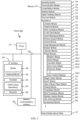
- Memory 370 includes high-speed random access memory, such as DRAM, SRAM, DDR RAM, or other random access solid state memory devices; and optionally includes non-volatile memory, such as one or more magnetic disk storage devices, optical disk storage devices, flash memory devices, or other non-volatile solid state storage devices. Memory 370 optionally includes one or more storage devices remotely located from CPU(s) 310. In some embodiments, memory 370 stores programs, modules, and data structures analogous to the programs, modules, and data structures stored in memory 102 of portable multifunction device 100 ( FIG. 1A ), or a subset thereof. Furthermore, memory 370 optionally stores additional programs, modules, and data structures not present in memory 102 of portable multifunction device 100.
- memory 370 of device 300 optionally stores drawing module 380, presentation module 382, word processing module 384, website creation module 386, disk authoring module 388, and/or spreadsheet module 390, while memory 102 of portable multifunction device 100 ( FIG. 1A ) optionally does not store these modules.
- Each of the above-identified elements in FIG. 3 is, optionally, stored in one or more of the previously mentioned memory devices.
- Each of the above-identified modules corresponds to a set of instructions for performing a function described above.
- the above-identified modules or programs (e.g., sets of instructions) need not be implemented as separate software programs, procedures, or modules, and thus various subsets of these modules are, optionally, combined or otherwise rearranged in various embodiments.
- memory 370 optionally stores a subset of the modules and data structures identified above. Furthermore, memory 370 optionally stores additional modules and data structures not described above.
- FIG. 4A illustrates an exemplary user interface for a menu of applications on portable multifunction device 100 in accordance with some embodiments. Similar user interfaces are, optionally, implemented on device 300.
- user interface 400 includes the following elements, or a subset or superset thereof:
- icon labels illustrated in FIG. 4A are merely exemplary.
- icon 422 for video and music player module 152 is labeled "Music" or "Music Player.”
- Other labels are, optionally, used for various application icons.
- a label for a respective application icon includes a name of an application corresponding to the respective application icon.
- a label for a particular application icon is distinct from a name of an application corresponding to the particular application icon.
- FIG. 4B illustrates an exemplary user interface on a device (e.g., device 300, FIG. 3 ) with a touch-sensitive surface 451 (e.g., a tablet or touchpad 355, FIG. 3 ) that is separate from the display 450 (e.g., touch screen display 112).
- Device 300 also, optionally, includes one or more contact intensity sensors (e.g., one or more of sensors 359) for detecting intensity of contacts on touch-sensitive surface 451 and/or one or more tactile output generators 357 for generating tactile outputs for a user of device 300.
- one or more contact intensity sensors e.g., one or more of sensors 359
- tactile output generators 357 for generating tactile outputs for a user of device 300.
- the device detects inputs on a touch-sensitive surface that is separate from the display, as shown in FIG. 4B .
- the touch-sensitive surface e.g., 451 in FIG. 4B
- the touch-sensitive surface has a primary axis (e.g., 452 in FIG. 4B ) that corresponds to a primary axis (e.g., 453 in FIG. 4B ) on the display (e.g., 450).
- the device detects contacts (e.g., 460 and 462 in FIG.
- finger inputs e.g., finger contacts, finger tap gestures, finger swipe gestures
- one or more of the finger inputs are replaced with input from another input device (e.g., a mouse-based input or stylus input).
- a swipe gesture is, optionally, replaced with a mouse click (e.g., instead of a contact) followed by movement of the cursor along the path of the swipe (e.g., instead of movement of the contact).
- a tap gesture is, optionally, replaced with a mouse click while the cursor is located over the location of the tap gesture (e.g., instead of detection of the contact followed by ceasing to detect the contact).
- multiple user inputs are simultaneously detected, it should be understood that multiple computer mice are, optionally, used simultaneously, or a mouse and finger contacts are, optionally, used simultaneously.
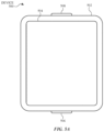
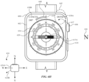
- FIG. 5A illustrates exemplary personal electronic device 500.
- Device 500 includes body 502.
- device 500 can include some or all of the features described with respect to devices 100 and 300 (e.g., FIGS. 1A-4B ).
- device 500 has touch-sensitive display screen 504, hereafter touch screen 504.
- touch screen 504 optionally includes one or more intensity sensors for detecting intensity of contacts (e.g., touches) being applied.
- the one or more intensity sensors of touch screen 504 (or the touch-sensitive surface) can provide output data that represents the intensity of touches.
- the user interface of device 500 can respond to touches based on their intensity, meaning that touches of different intensities can invoke different user interface operations on device 500.
- Exemplary techniques for detecting and processing touch intensity are found, for example, in related applications: International Patent Application Serial No. PCT/US2013/040061, titled “Device, Method, and Graphical User Interface for Displaying User Interface Objects Corresponding to an Application,” filed May 8, 2013 , published as WIPO Publication No. WO/2013/169849 , and International Patent Application Serial No. PCT/US2013/069483, titled “Device, Method, and Graphical User Interface for Transitioning Between Touch Input to Display Output Relationships," filed November 11, 2013 , published as WIPO Publication No. WO/2014/105276 .
- device 500 has one or more input mechanisms 506 and 508.
- Input mechanisms 506 and 508, if included, can be physical. Examples of physical input mechanisms include push buttons and rotatable mechanisms.
- device 500 has one or more attachment mechanisms. Such attachment mechanisms, if included, can permit attachment of device 500 with, for example, hats, eyewear, earrings, necklaces, shirts, jackets, bracelets, watch straps, chains, trousers, belts, shoes, purses, backpacks, and so forth. These attachment mechanisms permit device 500 to be worn by a user.
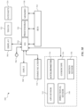
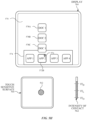
- FIG. 5B depicts exemplary personal electronic device 500.
- device 500 can include some or all of the components described with respect to FIGS. 1A , 1B , and 3 .
- Device 500 has bus 512 that operatively couples I/O section 514 with one or more computer processors 516 and memory 518.
- I/O section 514 can be connected to display 504, which can have touch-sensitive component 522 and, optionally, intensity sensor 524 (e.g., contact intensity sensor).
- I/O section 514 can be connected with communication unit 530 for receiving application and operating system data, using Wi-Fi, Bluetooth, near field communication (NFC), cellular, and/or other wireless communication techniques.
- Device 500 can include input mechanisms 506 and/or 508.
- Input mechanism 506 is, optionally, a rotatable input device or a depressible and rotatable input device, for example.
- Input mechanism 508 is, optionally, a button, in some examples.
- Input mechanism 508 is, optionally, a microphone, in some examples.
- Personal electronic device 500 optionally includes various sensors, such as GPS sensor 532, accelerometer 534, directional sensor 540 (e.g., compass), gyroscope 536, motion sensor 538, and/or a combination thereof, all of which can be operatively connected to I/O section 514.
- sensors such as GPS sensor 532, accelerometer 534, directional sensor 540 (e.g., compass), gyroscope 536, motion sensor 538, and/or a combination thereof, all of which can be operatively connected to I/O section 514.
- Memory 518 of personal electronic device 500 can include one or more non-transitory computer-readable storage mediums, for storing computer-executable instructions, which, when executed by one or more computer processors 516, for example, can cause the computer processors to perform the techniques described below, including method 700.
- a computer-readable storage medium can be any medium that can tangibly contain or store computer-executable instructions for use by or in connection with the instruction execution system, apparatus, or device.
- the storage medium is a transitory computer-readable storage medium.
- the storage medium is a non-transitory computer-readable storage medium.
- the non-transitory computer-readable storage medium can include, but is not limited to, magnetic, optical, and/or semiconductor storages.
- Personal electronic device 500 is not limited to the components and configuration of FIG. 5B , but can include other or additional components in multiple configurations.
- the term "affordance” refers to a user-interactive graphical user interface object that is, optionally, displayed on the display screen of devices 100, 300, and/or 500 ( FIGS. 1A , 3 , and 5A-5B ).
- an image e.g., icon
- a button e.g., button
- text e.g., hyperlink
- the term "focus selector” refers to an input element that indicates a current part of a user interface with which a user is interacting.
- the cursor acts as a "focus selector” so that when an input (e.g., a press input) is detected on a touch-sensitive surface (e.g., touchpad 355 in FIG. 3 or touch-sensitive surface 451 in FIG. 4B ) while the cursor is over a particular user interface element (e.g., a button, window, slider, or other user interface element), the particular user interface element is adjusted in accordance with the detected input.
- a touch screen display e.g., touch-sensitive display system 112 in FIG.
- a detected contact on the touch screen acts as a "focus selector" so that when an input (e.g., a press input by the contact) is detected on the touch screen display at a location of a particular user interface element (e.g., a button, window, slider, or other user interface element), the particular user interface element is adjusted in accordance with the detected input.
- an input e.g., a press input by the contact
- a particular user interface element e.g., a button, window, slider, or other user interface element
- focus is moved from one region of a user interface to another region of the user interface without corresponding movement of a cursor or movement of a contact on a touch screen display (e.g., by using a tab key or arrow keys to move focus from one button to another button); in these implementations, the focus selector moves in accordance with movement of focus between different regions of the user interface.
- the focus selector is generally the user interface element (or contact on a touch screen display) that is controlled by the user so as to communicate the user's intended interaction with the user interface (e.g., by indicating, to the device, the element of the user interface with which the user is intending to interact).
- a focus selector e.g., a cursor, a contact, or a selection box
- a press input is detected on the touch-sensitive surface (e.g., a touchpad or touch screen) will indicate that the user is intending to activate the respective button (as opposed to other user interface elements shown on a display of the device).
- the term "characteristic intensity" of a contact refers to a characteristic of the contact based on one or more intensities of the contact.
- the characteristic intensity is based on multiple intensity samples.
- the characteristic intensity is, optionally, based on a predefined number of intensity samples, or a set of intensity samples collected during a predetermined time period (e.g., 0.05, 0.1, 0.2, 0.5, 1, 2, 5, 10 seconds) relative to a predefined event (e.g., after detecting the contact, prior to detecting liftoff of the contact, before or after detecting a start of movement of the contact, prior to detecting an end of the contact, before or after detecting an increase in intensity of the contact, and/or before or after detecting a decrease in intensity of the contact).
- a predefined time period e.g., 0.05, 0.1, 0.2, 0.5, 1, 2, 5, 10 seconds
- a characteristic intensity of a contact is, optionally, based on one or more of: a maximum value of the intensities of the contact, a mean value of the intensities of the contact, an average value of the intensities of the contact, a top 10 percentile value of the intensities of the contact, a value at the half maximum of the intensities of the contact, a value at the 90 percent maximum of the intensities of the contact, or the like.
- the duration of the contact is used in determining the characteristic intensity (e.g., when the characteristic intensity is an average of the intensity of the contact over time).
- the characteristic intensity is compared to a set of one or more intensity thresholds to determine whether an operation has been performed by a user.
- the set of one or more intensity thresholds optionally includes a first intensity threshold and a second intensity threshold.
- a contact with a characteristic intensity that does not exceed the first threshold results in a first operation
- a contact with a characteristic intensity that exceeds the first intensity threshold and does not exceed the second intensity threshold results in a second operation
- a contact with a characteristic intensity that exceeds the second threshold results in a third operation.
- a comparison between the characteristic intensity and one or more thresholds is used to determine whether or not to perform one or more operations (e.g., whether to perform a respective operation or forgo performing the respective operation), rather than being used to determine whether to perform a first operation or a second operation.
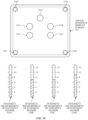
- FIG. 5C illustrates detecting a plurality of contacts 552A-552E on touch-sensitive display screen 504 with a plurality of intensity sensors 524A-524D.
- FIG. 5C additionally includes intensity diagrams that show the current intensity measurements of the intensity sensors 524A-524D relative to units of intensity.
- the intensity measurements of intensity sensors 524A and 524D are each 9 units of intensity
- the intensity measurements of intensity sensors 524B and 524C are each 7 units of intensity.
- an aggregate intensity is the sum of the intensity measurements of the plurality of intensity sensors 524A-524D, which in this example is 32 intensity units.
- each contact is assigned a respective intensity that is a portion of the aggregate intensity.
- each of contacts 552A, 552B, and 552E are assigned an intensity of contact of 8 intensity units of the aggregate intensity
- each of contacts 552C and 552D are assigned an intensity of contact of 4 intensity units of the aggregate intensity.
- Ij A ⁇ (Dj/ ⁇ Di)
- Dj is the distance of the respective contact j to the center of force
- the operations described with reference to FIGS. 5C-5D can be performed using an electronic device similar or identical to device 100, 300, or 500.
- a characteristic intensity of a contact is based on one or more intensities of the contact.
- the intensity sensors are used to determine a single characteristic intensity (e.g., a single characteristic intensity of a single contact). It should be noted that the intensity diagrams are not part of a displayed user interface, but are included in FIGS. 5C-5D to aid the reader.
- a portion of a gesture is identified for purposes of determining a characteristic intensity.
- a touch-sensitive surface optionally receives a continuous swipe contact transitioning from a start location and reaching an end location, at which point the intensity of the contact increases.
- the characteristic intensity of the contact at the end location is, optionally, based on only a portion of the continuous swipe contact, and not the entire swipe contact (e.g., only the portion of the swipe contact at the end location).
- a smoothing algorithm is, optionally, applied to the intensities of the swipe contact prior to determining the characteristic intensity of the contact.
- the smoothing algorithm optionally includes one or more of: an unweighted sliding-average smoothing algorithm, a triangular smoothing algorithm, a median filter smoothing algorithm, and/or an exponential smoothing algorithm.
- these smoothing algorithms eliminate narrow spikes or dips in the intensities of the swipe contact for purposes of determining a characteristic intensity.
- the intensity of a contact on the touch-sensitive surface is, optionally, characterized relative to one or more intensity thresholds, such as a contact-detection intensity threshold, a light press intensity threshold, a deep press intensity threshold, and/or one or more other intensity thresholds.
- the light press intensity threshold corresponds to an intensity at which the device will perform operations typically associated with clicking a button of a physical mouse or a trackpad.
- the deep press intensity threshold corresponds to an intensity at which the device will perform operations that are different from operations typically associated with clicking a button of a physical mouse or a trackpad.
- the device when a contact is detected with a characteristic intensity below the light press intensity threshold (e.g., and above a nominal contact-detection intensity threshold below which the contact is no longer detected), the device will move a focus selector in accordance with movement of the contact on the touch-sensitive surface without performing an operation associated with the light press intensity threshold or the deep press intensity threshold.
- a characteristic intensity below the light press intensity threshold e.g., and above a nominal contact-detection intensity threshold below which the contact is no longer detected
- these intensity thresholds are consistent between different sets of user interface figures.
- a decrease of characteristic intensity of the contact from an intensity above the contact-detection intensity threshold to an intensity below the contact-detection intensity threshold is sometimes referred to as detecting liftoff of the contact from the touch-surface.
- the contact-detection intensity threshold is zero. In some embodiments, the contact-detection intensity threshold is greater than zero.
- the press input includes an increase in intensity of the respective contact above the press-input intensity threshold and a subsequent decrease in intensity of the contact below the press-input intensity threshold, and the respective operation is performed in response to detecting the subsequent decrease in intensity of the respective contact below the press-input threshold (e.g., an "up stroke" of the respective press input).
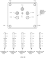
- FIGS. 5E-5H illustrate detection of a gesture that includes a press input that corresponds to an increase in intensity of a contact 562 from an intensity below a light press intensity threshold (e.g., "IT L ”) in FIG. 5E , to an intensity above a deep press intensity threshold (e.g., "IT D ”) in FIG. 5H .
- the gesture performed with contact 562 is detected on touch-sensitive surface 560 while cursor 576 is displayed over application icon 572B corresponding to App 2, on a displayed user interface 570 that includes application icons 572A-572D displayed in predefined region 574.
- the gesture is detected on touch-sensitive display 504.
- the intensity sensors detect the intensity of contacts on touch-sensitive surface 560.
- the device determines that the intensity of contact 562 peaked above the deep press intensity threshold (e.g., "IT D ").
- Contact 562 is maintained on touch-sensitive surface 560.
- reduced-scale representations 578A-578C e.g., thumbnails
- the intensity which is compared to the one or more intensity thresholds, is the characteristic intensity of a contact. It should be noted that the intensity diagram for contact 562 is not part of a displayed user interface, but is included in FIGS. 5E-5H to aid the reader.
- the display of representations 578A-578C includes an animation.
- representation 578A is initially displayed in proximity of application icon 572B, as shown in FIG. 5F .
- representation 578A moves upward and representation 578B is displayed in proximity of application icon 572B, as shown in FIG. 5G .
- representations 578A moves upward, 578B moves upward toward representation 578A, and representation 578C is displayed in proximity of application icon 572B, as shown in FIG. 5H .
- Representations 578A-578C form an array above icon 572B.
- the animation progresses in accordance with an intensity of contact 562, as shown in FIGS.
- the intensity, on which the progress of the animation is based is the characteristic intensity of the contact.
- the operations described with reference to FIGS. 5E-5H can be performed using an electronic device similar or identical to device 100, 300, or 500.
- the device employs intensity hysteresis to avoid accidental inputs sometimes termed "jitter," where the device defines or selects a hysteresis intensity threshold with a predefined relationship to the press-input intensity threshold (e.g., the hysteresis intensity threshold is X intensity units lower than the press-input intensity threshold or the hysteresis intensity threshold is 75%, 90%, or some reasonable proportion of the press-input intensity threshold).
- the hysteresis intensity threshold is X intensity units lower than the press-input intensity threshold or the hysteresis intensity threshold is 75%, 90%, or some reasonable proportion of the press-input intensity threshold.
- the press input includes an increase in intensity of the respective contact above the press-input intensity threshold and a subsequent decrease in intensity of the contact below the hysteresis intensity threshold that corresponds to the press-input intensity threshold, and the respective operation is performed in response to detecting the subsequent decrease in intensity of the respective contact below the hysteresis intensity threshold (e.g., an "up stroke" of the respective press input).
- the press input is detected only when the device detects an increase in intensity of the contact from an intensity at or below the hysteresis intensity threshold to an intensity at or above the press-input intensity threshold and, optionally, a subsequent decrease in intensity of the contact to an intensity at or below the hysteresis intensity, and the respective operation is performed in response to detecting the press input (e.g., the increase in intensity of the contact or the decrease in intensity of the contact, depending on the circumstances).
- the descriptions of operations performed in response to a press input associated with a press-input intensity threshold or in response to a gesture including the press input are, optionally, triggered in response to detecting either: an increase in intensity of a contact above the press-input intensity threshold, an increase in intensity of a contact from an intensity below the hysteresis intensity threshold to an intensity above the press-input intensity threshold, a decrease in intensity of the contact below the press-input intensity threshold, and/or a decrease in intensity of the contact below the hysteresis intensity threshold corresponding to the press-input intensity threshold.
- the operation is, optionally, performed in response to detecting a decrease in intensity of the contact below a hysteresis intensity threshold corresponding to, and lower than, the press-input intensity threshold.
- UI user interfaces
- portable multifunction device 100 such as portable multifunction device 100, device 300, or device 500.
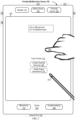
- FIGS. 6A-6X illustrate exemplary user interfaces for providing compass application features, in accordance with some embodiments.
- the user interfaces in these figures are used to illustrate the processes described below, including the processes in FIG. 7 .
- FIGS. 6A-6X illustrate exemplary user interfaces for a compass application, in accordance with some embodiments.
- the user interfaces in these figures are used to illustrate the processes described below, including the processes in FIG. 7 .
- FIG. 6A depicts electronic device 600 displaying home screen 606 on display 602 (e.g., a touch-sensitive display).
- Home screen 606 includes a plurality of application icons for launching respective applications.
- electronic device 600 includes one or more features of device 100, device 300, or device 500.
- electronic device 600 includes rotatable input mechanism 604, which is also depressible.
- electronic device 600 includes one or more features of device 100, device 300, or device 500.
- a user performs a tap gesture to launch a compass application.
- electronic device 600 detects input 608 at a location corresponding to compass icon 610.
- electronic device 600 launches the compass application, and replaces display of home screen 606 with display of compass user interface 612 of a compass application.
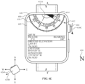
- Compass user interface 612 provides an indication of a direction in which electronic device 600 is oriented (e.g., 0° N).
- compass user interface 612 corresponds to a navigation mode for assisting a user with navigating a physical environment.
- Compass user interface 612 includes needle 614 and dial 616.
- Needle 614 provides an indication of one or more predefined directions. As shown in FIG. 6B , needle 614 points north and south. In particular, the side of needle 614 with the solid portion is pointing north, while the side of needle 614 with the crosshatching is pointing south.
- dial 616 provides an indication of one or more predefined directions. As depicted in FIG. 6B , dial 616 includes markings (e.g., ticks) corresponding to 0° to 359°. Dial 616 includes labels corresponding to the markings at certain intervals to provide an indication of respective predefined directions. For example, the marking corresponding to 0° is labeled "N" for north.
- the marking corresponding to 240° is labeled "240".
- needle 614, dial 616, or a combination thereof provides an indication of one or more predefined directions.
- the movement of needle 614 is fixed to the movement of dial 616, or vice versa.
- needle 614 does not move relative to dial 616.
- dial 616 is displayed without needle 614.
- Compass user interface 612 also includes direction of travel indicator 618, which provides an indication of the direction in which electronic device 600 is oriented and/or the direction in which the user intends to travel. Additionally, compass user interface 612 includes ring 620, which includes elevation, incline, latitude, and longitude.
- electronic device 600 is oriented in the north direction.
- electronic device 600 displays compass user interface 612 with an indication that electronic device 600 is oriented in the north direction.
- dial 616 is displayed such that the 0° N marking is aligned with direction of travel indicator 618.
- FIG. 6B depicts compass rose 624 and north indicator 626, which help to clarify the orientation of electronic device 600 with respect to north.
- compass rose 624 includes device representation 624A, which includes physical features (e.g., a representation of rotatable input mechanism 604) to illustrate the orientation of electronic device 600 with respect to compass rose 624.
- north indicator 626 is located in the north direction with respect to electronic device 600.
- FIGS. 6B-6D illustrate how compass user interface 612 is updated as electronic device 600 changes orientation relative to the north direction.
- FIG. 6B suppose the user wishes to travel west, so the user turns left towards the west direction. It is noted that, when the user turns, electronic device 600 moves in accordance with the movement of the user, as electronic device 600 is being worn on the user's wrist.
- FIG. 6C as a result of the user turning, electronic device 600 rotates dial 616 clockwise, and updates compass user interface 612 to reflect the new direction in which electronic device 600 is oriented.
- compass user interface 612 provides an indication that electronic device 600 is oriented in the northwest direction at 330°.
- electronic device 600 updates compass user interface 612 to provide an indication that electronic device 600 is oriented in the west direction at 270°.
- the accuracy of dial 616 and its indication of direction can vary.
- accuracy indicator 622 provides an indication of the accuracy of dial 616 and its indication of direction. For example, a high number of ticks (e.g., 5) in accuracy indicator 622 provides an indication that dial 616 has low accuracy.
- FIG. 6C depicts an improvement in accuracy of dial 616, as the number of ticks in accuracy indicator 622 decreases. As depicted in FIG. 6D , the ticks in accuracy indicator 622 cease to be displayed, indicating a high accuracy for dial 616.
- high accuracy for dial 616 can also be indicated by accuracy indicator 622 having a single tick.
- accuracy indicator 622 after receiving additional inputs that enable higher accuracy measurements of direction (e.g., after motion that enables improved calibration) the number of ticks in the accuracy indicator decreases to indicate the increased accuracy (or reduced uncertainty) of the measurement.
- the device determines that the measurements of direction have a reduced accuracy (e.g., due to motion of the device or interference with sensors of the device such as a nearby magnetic field) the number of ticks in the accuracy indicator increases to indicate the reduced accuracy (or increased uncertainty) of the measurement.
- a bearing represents a direction in which the user intends to travel, such as towards a landmark.
- electronic device 600 in response to detecting input 628 and in accordance with a determination that an intensity of input 628 exceeds an intensity threshold, replaces display of compass user interface 612 with display of bearing menu 634.
- Bearing menu 634 includes affordance 630A which, when selected, initiates a process for setting a bearing.
- electronic device 600 replaces display of compass user interface 612 with display of bearing menu 634 regardless of the location at which input 628 is detected.
- the user selects affordance 630A via a tap gesture.
- electronic device 600 detects tap gesture 632 at a location corresponding to affordance 630A.
- modified compass user interface 637 includes one or more features of compass user interface 612, including needle 614, dial 616, and direction of travel indicator 618. Additionally, modified compass user interface 637 includes done affordance 638A and cancel affordance 638B. In some embodiments, modified compass user interface 637 corresponds to an edit mode for setting a bearing.
- the user begins rotating rotatable input mechanism 604 counterclockwise to adjust the bearing towards a landmark in the southwest direction at 240°.
- electronic device 600 detects, via rotatable input mechanism 604, input 636A with a magnitude and directional component.
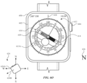
- bearing indicator 640 in response to detecting input 636A, displays bearing indicator 640, where the size of bearing indicator 640 is based on the magnitude of input 636A. Further, the displayed location of bearing indicator 640 is based on the directional component of input 636A. For example, in some embodiments, if the directional component of input 636A was in the opposite direction, bearing indicator 640 would be displayed to the right of direction of travel indicator 618. For ease of explanation, FIG. 6G depicts compass rose 624 with bearing direction 624B. Bearing direction 624B illustrates the direction of the bearing (e.g., 240°) relative to electronic device 600.
- bearing direction 624B illustrates the direction of the bearing (e.g., 240°) relative to electronic device 600.
- bearing indicator 640 In response to continued detection of input 636A, electronic device 600 increases the size of bearing indicator 640 based on the magnitude of input 636A.
- bearing indicator 640 increases in size such that bearing indicator 640 corresponds to 240° (e.g., the direction of the landmark towards which the user intends to travel).
- bearing indicator 640 represents an amount of offset from the current direction in which electronic device 600 is oriented.
- the user sets the bearing by selecting done affordance 638A via a tap gesture.
- electronic device 600 detects input 642 at a location corresponding to done affordance 638A.
- electronic device 600 replaces display of modified compass user interface 637 with display of compass user interface 612.
- Compass user interface 612 in FIG. 6I includes bearing indicator 640, which represents a bearing that is set at 240°.
- the bearing is set in the direction of a landmark at 240° to which the user intends to travel.
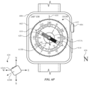
- the user is facing west at 270° from North.
- Bearing indicator 640 provides an indication that the user needs to turn left by a certain amount in order to face 240°. The user starts to turn left to face the landmark at 240°.
- electronic device 600 updates compass user interface 612 to reflect the new direction in which electronic device 600 is oriented.
- compass user interface 612 provides an indication that electronic device 600 is oriented in the southwest direction at 255° from North.
- updating compass user interface 612 includes changing bearing indicator 640 based on the movement of electronic device 600 relative to a predefined direction (e.g., north). As a result, bearing indicator 640 decreases in size as the electronic device 600 moves more closely towards the desired direction of 240°. At FIG. 6J , the user continues to turn left to face 240°.
- electronic device 600 faces the direction of the bearing at 240°. Accordingly, electronic device 600 updates user interface 612 to provide an indication that electronic device 600 is oriented in the southwest direction at 240°. At this point, the user and electronic device 600 are facing the landmark at 240°, and the user can travel towards the landmark using compass user interface 612 as a guide.
- rotating the rotatable input mechanism 604 at FIG. 6K does not change the bearing.
- electronic device 600 does not, for example, change the size of bearing indicator 640 in response to rotation of rotatable input mechanism 604 at FIG. 6K .
- the user rotates rotatable input mechanism 604 to scroll to the top of compass user interface 612.
- electronic device 600 detects input 636C, and in response, returns to displaying compass user interface 612, as shown in FIG. 6M .
- the user performs a deep press gesture to navigate back to bearing menu 634.
- electronic device 600 detects input 644.
- electronic device 600 detects input 646 at affordance 630A and, in response, electronic device 600 replaces display of bearing menu 634 with display of modified compass user interface 637 in FIG. 6F , with the exception that modified compass user interface 637 would reflect that electronic device 600 is oriented to 240° (e.g., the 240° marker of dial 616 would be aligned with direction of travel indicator 618).
- FIG. 6N depicts compass user interface 612.
- FIG. 6O in response to detecting input 650, electronic device 600 returns to displaying compass user interface 612.
- FIG. 6N and previous figures depict compass user interface 612 with level indicator 613A.
- level indicator 613A is substantially centered relative to compass user interface 612 (e.g., dial 616), which provides an indication that electronic device 600 is substantially parallel to the ground.
- level indicator 613A in FIG. 6O is not substantially centered, which provides an indication that electronic device 600 is not substantially parallel to the ground. It is noted that level indicator 613A is used when electronic device 600 is oriented within a threshold range of orientations that correspond to measuring an orientation of the device relative to the ground.
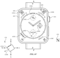
- FIG. 6V-6X depict alternative clock faces for displaying data from the compass application.
- electronic device 600 displays clock face 658, which includes complications 658A-658G and 656D.
- Complications 658A-658B provide indications of latitude and longitude, respectively.
- complications 658A-658B include numerical values for latitude and longitude, as shown in FIG. 6V .
- Complications 658C-658E and 658G provide an indication of the direction (e.g., 240°) in which electronic device 600 is oriented relative to a predefined direction (e.g., north).
- complication 658F provides an indication of the elevation of electronic device 600.
- clock face 656 which has been configured to display a different arrangement of complications, as compared to FIG. 6U .
- clock face 656 in FIG. 6W does not include complication 656B of FIG. 6U .
- clock face 656 includes complication 656A at a new location as compared to FIG. 6U .
- clock face 656 includes complication 656E, which provides an indication of the direction in which electronic device 600 is oriented relative to a predefined direction.
- electronic device 600 displays clock face 660 with complication 660A, which also provides an indication of the direction in which electronic device 600 is oriented relative to a predefined direction.
- FIG. 7 is a flow diagram illustrating an exemplary process for a compass application, in accordance with some embodiments.
- Method 700 is performed at a device (e.g., 100, 300, 500, 600) with a display device and a rotatable input mechanism (e.g., a physical crown that has a fixed axis about which the physical crown rotates relative to the display device and a housing of the electronic device).
- a rotatable input mechanism e.g., a physical crown that has a fixed axis about which the physical crown rotates relative to the display device and a housing of the electronic device.
- method 700 provides an intuitive way for setting a bearing in a compass application.
- the method reduces the cognitive burden on a user for setting a bearing, thereby creating a more efficient human-machine interface.
- the direction indicator (e.g., 614, 616) includes one or more of numerical elements (e.g., degrees), textual elements (e.g., cardinal directions), graphical dial (e.g., 616), and a graphical needle (e.g., 614).
- the location/orientation of the direction indicator on the display device changes (e.g., with respect to a fixed point on the display device) based on (e.g., in response to) a change in orientation of the device relative to the particular direction.
- the compass user interface (e.g., 637) includes a direction of travel indicator (e.g., 618), which is displayed at a fixed location/orientation on the display of the electronic device regardless of the change in orientation of the electronic device.
- the direction of travel indicator provides an indication of the orientation of the electronic device with respect to the environment (e.g., the direction the electronic device and, optionally, the user is facing) direction in which the user intends to travel.
- the location/orientation of the direction of travel indicator (on the display) does not change based on (e.g., in response to) a change in orientation of the device relative to the particular direction.)
- the bearing indicator (e.g., 640) includes a first point at a location (e.g., 618) corresponding to the respective compass direction (e.g., the direction in which the device is currently facing/oriented towards) and/or a second point at a location corresponding to the direction of the bearing indicator (e.g., the direction in which the user intends to travel).
- the bearing indicator includes a graphical arc between the first point and the second point.
- the graphical arc changes in size in response to the device (e.g., 600) detecting rotation of the rotatable input mechanism (e.g., 604).
- the user configures the bearing indicator to set a direction pointing at a landmark to which the user wants to travel.
- displaying the compass user interface (in the edit mode) (e.g., 637) includes changing visual characteristics (e.g., reducing opacity, darkening, blurring, ceasing display) of displayed elements (e.g., 614, 616) on the display device (e.g., the direction indicator or a portion thereof).)
- the electronic device While displaying the bearing indicator (e.g., 640) (in an edit mode), the electronic device (e.g., 600) detects (704) rotation (e.g., via input 636A) of the rotatable input mechanism (e.g., 604) (and, optionally, while concurrently displaying the bearing indicator and the direction indicator (e.g., 614, 616)).
- rotation e.g., via input 636A
- the rotatable input mechanism e.g., 604
- the direction indicator e.g., 614, 616)
- the electronic device In response (706) to detecting rotation of the rotatable input mechanism, the electronic device (e.g., 600) changes (708) the displayed position of the bearing indicator (e.g., 640) from a first position to a second position (e.g., relative to a position of the direction indicator) by an amount that is determined in accordance with a magnitude (and, optionally, direction) of the rotation (e.g., via input 636A) of the rotatable input mechanism (e.g., 604) (e.g., such that changing the position of the bearing indicator to the second position changes the amount of offset of the bearing indicator with the respective compass direction).
- a magnitude (and, optionally, direction) of the rotation e.g., via input 636A
- the rotatable input mechanism e.g., 604
- Changing the displayed position of the bearing indicator via the rotatable input mechanism allows the user to precisely set the bearing while the compass user interface is displayed on a small display.
- Use of the rotatable input mechanism enhances the operability of the device and makes the user-device interface more efficient (e.g., by helping the user efficiently set the bearing in the compass application) which, additionally, reduces power usage and improves battery life of the device by enabling the users to use the devices more quickly and efficiently.
- changing the displayed position of the bearing indicator includes rotating the bearing indicator (e.g., in cases where the bearing indicator is a needle similar to needle 614).
- a first point of the bearing indicator remains fixed while a second point of the bearing indicator changes.
- further detecting rotation of the rotatable input mechanism results in changing the displayed position of the bearing indication from the second position to a third position.
- detecting further rotation of the rotatable input mechanism results in changing the displayed position of the bearing indication from the third position to the first position.
- the amount of change in the displayed position of the bearing indicator is based on the detected amount (e.g., magnitude, speed, and/or duration) of rotation of the rotatable input mechanism. In some embodiments, the amount of change in the displayed position of the bearing indicator is proportional to the detected amount of rotation of the rotatable input mechanism.
- detecting a change in orientation of the electronic device (e.g., 600) relative to the respective compass direction causes the displayed position of the bearing indicator (e.g., 640) to change in the first mode (e.g., a non-edit mode, when compass user interface 612 is displayed).
- detecting a change in orientation of the electronic device relative to the respective compass direction does not cause the displayed position of the bearing indicator to change in the second mode (e.g., an edit mode, when compass user interface 637 is displayed).
- detecting rotation of the rotatable input mechanism causes the displayed position of the bearing indicator to change in the second mode (e.g., an edit mode, when compass user interface 637 is displayed). In some embodiments, detecting rotation of the rotatable input mechanism does not cause the displayed position of the bearing indicator to change in the first mode (e.g., a non-edit mode, when compass user interface 612 is displayed). In some embodiments, activating the "done" button (e.g., 638A) (e.g., while in the second mode, an edit mode) causes the bearing indicator to be set relative to north as shown on the display (e.g., 602).
- the "done" button e.g., 638A
- the displayed position of the bearing indicator does not change in response to the electronic device detecting a change in orientation of the electronic device relative to the respective compass direction.
- the electronic device prior to displaying the compass user interface (e.g., 637), displays, via the display device (e.g., 602), a second compass user interface (e.g., 612, a navigation mode, a first mode) with the direction indicator (e.g., 614, 616) and the bearing indicator (e.g., 640).
- the second compass user interface does not include the bearing indicator.
- the direction indicator provides an indication of the respective compass direction (e.g., a direction relative to the earth's magnetic field such as a cardinal direction (e.g., north (e.g., true north, magnetic north), south, west, east)).
- the appearance of the direction indicator is determined based on the orientation of the electronic device relative to the respective compass direction.
- the bearing indicator (e.g., 640) provides an indication of an offset (e.g., thus providing an indication of the direction to a destination to which the user intends to travel) from the respective compass direction (e.g., a direction relative to the earth's magnetic field) (e.g., while concurrently displaying the direction of travel indicator (e.g., 618)).
- the user configures the bearing indicator to set a direction pointing at a landmark to which the user wants to travel.
- the bearing indicator is configured to indicate that there is no offset from the respective compass direction.
- displaying the bearing setting user interface includes changing visual characteristics (e.g., reducing opacity, darkening, blurring, ceasing display) of displayed elements on the display device (e.g., the direction indicator or a portion thereof).
- the bearing indicator includes a first point at a location corresponding to the respective compass direction (e.g., the direction in which the device is currently facing/oriented towards) and/or a second point at a location corresponding to the direction of the bearing indicator (e.g., the direction in which the user intends to travel).
- the bearing indicator includes a graphical arc between the first point and the second point.
- the graphical arc changes in size in response to the device detecting a change in orientation relative to the respective compass direction.
- the electronic device is oriented directly towards the direction of the bearing indicator (e.g., the direction in which the user intends to travel).
- the bearing indicator continues to be displayed.
- the electronic device while displaying the bearing indicator (e.g., 640) (in the first position, in the navigation mode (e.g., when compass user interface 612 is displayed) different from the edit mode), the electronic device (e.g., 600) detects rotation (e.g., via input 636B) of the rotatable input mechanism (e.g., 604) (and, optionally, while concurrently displaying the bearing indicator and the direction indicator).
- the electronic device in response to detecting rotation of the rotatable input mechanism, forgoes changing the displayed position of (e.g., forgoing rotating) the bearing indicator (e.g., 640) relative to the direction indicator (e.g., 614, 616) (e.g., thereby not changing the amount of offset of the bearing indicator with the respective compass direction).
- Forgoing changing the displayed position in response to detecting rotation of the rotatable input mechanism requires the user to enter an edit mode to set the bearing. Since the user needs to enter an edit mode to adjust the bearing using the rotatable input mechanism, accidental changes to a previously set bearing (e.g., the current bearing setting) are avoided while in the navigation mode.
- Preventing unintentional changes to the set bearing enhances the operability of the device and makes the user-device interface more efficient (e.g., by helping to avoid extraneous inputs that would otherwise be needed to correct the set bearing) which, additionally, reduces power usage and improves battery life of the device by enabling the user to use the device more quickly and efficiently.
- the electronic device displays (concurrently with the direction indicator and the bearing indicator), via the display device (e.g., 602), a first representation of a first geographic information (e.g., longitude as depicted in ring 620 of FIG. 6B , a geographic coordinate that specifies the east-west position of the electronic device on the Earth's surface) of the electronic device and a second representation of a second geographic information (e.g., latitude as depicted in ring 620 of FIG. 6B , a geographic coordinate that specifies the north-south position of the electronic device on the Earth's surface) of the electronic device.
- a first geographic information e.g., longitude as depicted in ring 620 of FIG. 6B , a geographic coordinate that specifies the east-west position of the electronic device on the Earth's surface
- a second geographic information e.g., latitude as depicted in ring 620 of FIG. 6B , a geographic coordinate that specifies the north-south position
- Exemplary geographic information of the electronic device includes: geographic coordinates (longitude, latitude) of the location electronic device, elevation (e.g., height above or below a fixed reference point (such as the surface of the Earth or sea level) as depicted in ring 620 of FIG. 6B ) of the location of the electronic device, and incline (e.g., angle from horizontal as depicted in ring 620 of FIG. 6B ) of the orientation of the electronic device.
- the first representation of the first geographic information and the second representation of the second geographic information are arranged in a circle (e.g., 620) or an arc (a minor arc, a major arc) of a circle.
- the direction indicator (e.g., 614, 616) and/or bearing indicator are configured to rotate using the center of the circle (e.g., 620) as a pivot point.
- the first representation of the first geographic information and the second representation of the second geographic information are displayed in both the edit mode (e.g., when compass user interface 637 is displayed) and the navigation mode (e.g., when compass user interface 612 is displayed).
- the display of the representations of the geographic information is updated live (e.g., continuously, periodically) based on information collected by the electronic device.
- the first representation of the first geographic information e.g., longitude as depicted in ring 620 of FIG. 6K
- a first size and optionally at a first orientation (e.g., non-horizontal) on the display device
- the second representation of the second geographic information e.g., latitude as depicted in ring 620 of FIG.
- the electronic device detects a scroll input (e.g., 636B) that includes a directional component (e.g., a swipe up input on a touch-sensitive surface, a rotation of the rotatable input mechanism (e.g., 604)).
- a scroll input e.g., 636B
- a directional component e.g., a swipe up input on a touch-sensitive surface, a rotation of the rotatable input mechanism (e.g., 604)
- the electronic device shifts the compass user interface (e.g., 612) in accordance with the directional component to display: a third representation (e.g., longitude information as depicted in the bottom portion of FIG. 6L ) of the first geographic information at a third size that is larger than the first size (and optionally at a third orientation (e.g., horizontal) different from the first orientation on the display device) and a fourth representation (e.g., latitude information as depicted in the bottom portion of FIG. 6L ) of the second geographic information at a fourth size that is larger than the second size (e.g., and at a fourth orientation (e.g., horizontal) different from the second orientation on the display device).
- a third representation e.g., longitude information as depicted in the bottom portion of FIG. 6L
- a fourth representation e.g., latitude information as depicted in the bottom portion of FIG. 6L
- detecting the scroll input causes the direction indicator (e.g., 614, 616) and the bearing indicator (e.g., 640) (or at least a portion thereof) to scroll off of the display (e.g., 602) and for geographic information to scroll onto the display (e.g., as shown in FIG. 6L ).
- the electronic device in response to detecting the scroll input (while in the navigation mode), displays one or more of (or all of) a numerical heading (e.g., in degrees) based on the orientation of the electronic device, a numerical incline (e.g., in degrees) based on the orientation of the electronic device, a numerical bearing (e.g., in degrees) that is not based on the orientation of the electronic device, a numerical ground elevation (e.g., in feet) that is based on the geographic location of the electronic device, a numerical longitude and numerical latitude (e.g., in degrees) that are based on the geographic location of the electronic device.
- a numerical heading e.g., in degrees
- a numerical incline e.g., in degrees
- a numerical bearing e.g., in degrees
- a numerical ground elevation e.g., in feet
- a numerical longitude and numerical latitude e.g., in degrees
- the third representation provides a more precise value for the first geographic information as compared to the first representation
- the fourth representation provides a more precise value for the second geographic information as compared to the second representation.
- the electronic device in response to detecting the scroll input, displays one or more additional geographic information(s) that were not displayed concurrently with the first representation of the first geographic information.
- the electronic device in response to detecting the scroll input (e.g., 636B, detecting rotation of the rotatable input mechanism (e.g., 604)), the electronic device forgoes changing the displayed position of (e.g., forgoing rotating) the bearing indicator (e.g., 640) relative to the direction indicator (e.g., 614, 616) (thereby not changing the amount of offset of the bearing indicator with the respective compass direction).
- the scroll input e.g., 636B, detecting rotation of the rotatable input mechanism (e.g., 604)
- the electronic device in response to detecting the scroll input (e.g., 636B, detecting rotation of the rotatable input mechanism (e.g., 604)), the electronic device forgoes changing the displayed position of (e.g., forgoing rotating) the bearing indicator (e.g., 640) relative to the direction indicator (e.g., 614, 616) (thereby not changing the amount of offset of the bearing indicator with the
- the displayed third representation of the first geographic information and the fourth representation of the second geographic information are updated (e.g., periodically, continuously, repeatedly) to reflect an updated location or orientation of the electronic device (e.g., 600).
- the electronic device displays (e.g., adjacent to the respective geographic information) an amount of time in which the respective geographic information was last updated (e.g., "7M AGO" as shown in FIG. 6 :).
- the displayed first representation of the first geographic information and the second representation of the second geographic information are updated (e.g., periodically, continuously, repeatedly) to reflect an updated location or orientation of the electronic device.
- the electronic device prior to displaying the compass user interface (e.g., 637), displays, via the display device (e.g., 602), the second compass user interface (e.g., 612, a navigation mode, a first mode) with the direction indicator (e.g., 614, 616) (and optionally without the bearing indicator (e.g., 640)).
- the display device e.g., 602
- the second compass user interface e.g., 612, a navigation mode, a first mode
- the direction indicator e.g., 614, 616
- the bearing indicator e.g., 640
- the direction indicator provides an indication of the respective compass direction (e.g., a direction relative to the earth's magnetic field such as a cardinal direction (e.g., north (e.g., true north, magnetic north), south, west, east)), wherein the appearance of the direction indicator is determined based on the orientation of the electronic device relative to the respective compass direction.
- a direction relative to the earth's magnetic field such as a cardinal direction (e.g., north (e.g., true north, magnetic north), south, west, east)
- north e.g., true north, magnetic north
- the electronic device detects, via the touch-sensitive surface (e.g., of display device 602), a user input (e.g., 628, at a location corresponding to the second compass user interface (e.g., 612), at a location corresponding to the direction indicator (e.g., 614, 616).
- a user input e.g., 628
- the second compass user interface e.g., 612
- the direction indicator e.g., 614, 616
- the electronic device in response to detecting the user input (e.g., 628): in accordance with a determination that a characteristic intensity of the user input exceeds an intensity threshold (e.g., a non-zero threshold), the electronic device displays an edit affordance (e.g., 630A) which, when selected, results in display of the compass user interface (e.g., 637) (e.g., 637, edit mode, a second mode) (and optionally independent of a location of the user input (e.g., 628) on the touch-sensitive surface). Requiring the user to enter an edit mode to set the bearing prevents accidental changes to the set bearing while in the navigation mode.
- an intensity threshold e.g., a non-zero threshold
Landscapes
- Engineering & Computer Science (AREA)
- Theoretical Computer Science (AREA)
- General Engineering & Computer Science (AREA)
- Physics & Mathematics (AREA)
- General Physics & Mathematics (AREA)
- Human Computer Interaction (AREA)
- Remote Sensing (AREA)
- Radar, Positioning & Navigation (AREA)
- Computer Hardware Design (AREA)
- Automation & Control Theory (AREA)
- Signal Processing (AREA)
- Computer Networks & Wireless Communication (AREA)
- User Interface Of Digital Computer (AREA)
Claims (15)
- Verfahren, umfassend:
an einer elektronischen Vorrichtung mit einer Anzeigevorrichtung und einem drehbaren Eingabemechanismus (604),
Anzeigen (702), über die Anzeigevorrichtung, einer Kompassbenutzerschnittstelle mit einem ersten Richtungsindikator und einem ersten Kursindikator, wobei:der Richtungsindikator eine Angabe einer jeweiligen Kompassrichtung bereitstellt, wobei das Erscheinungsbild des Richtungsindikators basierend auf der Ausrichtung der elektronischen Vorrichtung relativ zu der jeweiligen Kompassrichtung bestimmt wird; undder erste Kursindikator (640) eine Angabe eines Versatzes von der jeweiligen Kompassrichtung bereitstellt;während sich die elektronische Vorrichtung in einem Bearbeitungsmodus befindet und den Richtungsindikator und den ersten Kursindikator über die Anzeigevorrichtung gleichzeitig anzeigt (704), Detektieren einer ersten Drehung des drehbaren Eingabemechanismus;als Reaktion (706) auf das Detektieren der ersten Drehung des drehbaren Eingabemechanismus:
Ändern (708) der angezeigten Position des ersten Kursindikators von einer ersten Position zu einer zweiten Position um einen Betrag, der in Übereinstimmung mit einer Größenordnung der Drehung des drehbaren Eingabemechanismus bestimmt wird;während sich die elektronische Vorrichtung in einem Nicht-Bearbeitungsmodus befindet, Detektieren einer zweiten Drehung des drehbaren Eingabemechanismus; undals Reaktion auf das Detektieren der zweiten Drehung des drehbaren Eingabemechanismus:Unterlassen des Änderns der angezeigten Position des ersten Kursindikators relativ zu dem Richtungsindikator; undAnzeigen eines nummerischen Kursindikators, der eine Angabe des Versatzes von der jeweiligen Kompassrichtung bereitstellt, wobei sich der nummerische Kursindikator von dem ersten Kursindikator unterscheidet. - Verfahren nach Anspruch 1, ferner umfassend:vor dem Anzeigen der Kompassbenutzerschnittstelle, Anzeigen, über die Anzeigevorrichtung, einer zweiten Kompassbenutzerschnittstelle mit dem Richtungsindikator und dem ersten Kursindikator, wobei:der Richtungsindikator eine Angabe der jeweiligen Kompassrichtung bereitstellt, wobei das Erscheinungsbild des Richtungsindikators basierend auf der Ausrichtung der elektronischen Vorrichtung relativ zu der jeweiligen Kompassrichtung bestimmt wird; undder erste Kursindikator eine Angabe eines Versatzes von der jeweiligen Kompassrichtung bereitstellt;während des Anzeigens des ersten Kursindikators, Detektieren von Drehung des drehbaren Eingabemechanismus; undals Reaktion auf das Detektieren von Drehung des drehbaren Eingabemechanismus, Unterlassen des Änderns der angezeigten Position des ersten Kursindikators relativ zu dem Richtungsindikator.
- Verfahren nach einem der Ansprüche 1-2, wobei das Anzeigen der Kompassbenutzerschnittstelle ferner Folgendes beinhaltet:
Anzeigen, über die Anzeigevorrichtung, einer ersten Darstellung von ersten geografischen Informationen der elektronischen Vorrichtung und einer zweiten Darstellung von zweiten geografischen Informationen der elektronischen Vorrichtung. - Verfahren nach Anspruch 3, ferner umfassend:während des Anzeigens der ersten Darstellung der ersten geografischen Informationen in einer ersten Größe und der zweiten Darstellung der zweiten geografischen Informationen in einer zweiten Größe, Detektieren einer Scroll-Eingabe, die eine Richtungskomponente beinhaltet; undals Reaktion auf das Detektieren der Scroll-Eingabe, Verschieben der Kompassbenutzerschnittstelle in Übereinstimmung mit der Richtungskomponente, um Folgendes anzuzeigen:
eine dritte Darstellung der ersten geografischen Informationen in einer dritten Größe, die größer als die erste Größe ist, und eine vierte Darstellung der zweiten geografischen Informationen in einer vierten Größe, die größer als die zweite Größe ist. - Verfahren nach einem der Ansprüche 2-4, wobei die elektronische Vorrichtung eine berührungsempfindliche Fläche beinhaltet und das Verfahren ferner Folgendes umfasst:vor dem Anzeigen der Kompassbenutzerschnittstelle, Anzeigen, über die Anzeigevorrichtung, der zweiten Kompassbenutzerschnittstelle mit dem Richtungsindikator, wobei:
der Richtungsindikator eine Angabe der jeweiligen Kompassrichtung bereitstellt, wobei das Erscheinungsbild des Richtungsindikators basierend auf der Ausrichtung der elektronischen Vorrichtung relativ zu der jeweiligen Kompassrichtung bestimmt wird; undDetektieren, über die berührungsempfindliche Fläche, einer Benutzereingabe; undals Reaktion auf das Detektieren der Benutzereingabe:in Übereinstimmung mit einer Bestimmung, dass eine Eigenschaftsintensität der Benutzereingabe einen Intensitätsschwellenwert überschreitet, Anzeigen einer Bearbeitungsaffordanz, die bei Auswahl dazu führt, dass in den Bearbeitungsmodus eingetreten und die Kompassbenutzerfläche angezeigt wird; undin Übereinstimmung mit einer Bestimmung, dass die Eigenschaftsintensität der Benutzereingabe den Intensitätsschwellenwert nicht überschreitet, Unterlassen des Anzeigens der Bearbeitungsaffordanz. - Verfahren nach einem der Ansprüche 2-5, wobei das Anzeigen der Kompassbenutzerschnittstelle in dem Bearbeitungsmodus Anzeigen einer Abschlussaffordanz beinhaltet und das Verfahren ferner Folgendes umfasst:nach dem Ändern der angezeigten Position des ersten Kursindikators von der ersten Position zu der zweiten Position, Empfangen einer zweiten Benutzereingabe; undals Reaktion auf das Empfangen der zweiten Benutzereingabe:
in Übereinstimmung mit einer Bestimmung, dass die zweite Benutzereingabe einer Aktivierung der Abschlussaffordanz entspricht, Übergehen aus der Kompassbenutzerschnittstelle zu der zweiten Kompassbenutzerschnittstelle und in den Nicht-Bearbeitungsmodus und Beibehalten der angezeigten Position des ersten Kursindikators in der zweiten Position. - Verfahren nach einem der Ansprüche 2-6, ferner umfassend:während des Anzeigens der zweiten Kompassbenutzerschnittstelle, die den Richtungsindikator beinhaltet, Detektieren einer Ausrichtungsänderung der elektronischen Vorrichtung; undals Reaktion auf das Detektieren der Ausrichtungsänderung der elektronischen Vorrichtung, Anzeigen einer Angabe eines Versatzbetrags, um den die elektronische Vorrichtung relativ zu einer fixen Ausrichtung ausgerichtet ist.
- Verfahren nach einem der Ansprüche 1-7, wobei das Anzeigen des Richtungsindikators Anzeigen einer Genauigkeitsangabe des Richtungsindikators beinhaltet und das Verfahren ferner Folgendes umfasst:in Übereinstimmung mit einer Bestimmung, dass die Genauigkeit des Richtungsindikators einen ersten Genauigkeitsgrad aufweist, Anzeigen der Genauigkeitsangabe mit einem ersten Erscheinungsbild; undin Übereinstimmung mit einer Bestimmung, dass die Genauigkeit des Richtungsindikators einen zweiten Genauigkeitsgrad aufweist, der sich von dem ersten Genauigkeitsgrad unterscheidet, Anzeigen der Genauigkeitsangabe mit einem zweiten Erscheinungsbild, das sich von dem ersten Erscheinungsbild unterscheidet.
- Verfahren nach einem der Ansprüche 1-7, umfassend:
vor dem Anzeigen der Kompassbenutzerschnittstelle:Initiieren eines Prozesses zum Detektieren von Sensordaten;in Übereinstimmung damit, dass Detektieren von Daten, die ein Suffizienzkriterium erfüllen, fehlschlägt, Anzeigen einer Angabe, dass das Suffizienzkriterium nicht erfüllt wurde; undin Übereinstimmung damit, dass Daten detektiert werden, die das Suffizienzkriterium erfüllen, Unterlassen des Anzeigens der Angabe, dass das Suffizienzkriterium nicht erfüllt wurde. - Verfahren nach einem der Ansprüche 1-8, umfassend:während des Anzeigens des Richtungsindikators, Detektieren einer dritten Benutzereingabe;als Reaktion auf das Detektieren der dritten Benutzereingabe, Anzeigen einer Uhrenoberfläche, welche die aktuelle Uhrzeit angibt, wobei die Uhrenoberfläche ferner ein Kompassobjekt beinhaltet;während des Anzeigens der Uhrenoberfläche, welche die aktuelle Uhrzeit angibt und das Kompassobjekt beinhaltet, Detektieren von Aktivierung des Kompassobjekts; undals Reaktion auf das Detektieren von Aktivierung des Kompassobjekts, Anzeigen einer zweiten Kompassbenutzerschnittstelle, die den Richtungsindikator beinhaltet, der eine Angabe der jeweiligen Kompassrichtung bereitstellt, wobei das Erscheinungsbild des Richtungsindikators basierend auf der Ausrichtung der elektronischen Vorrichtung relativ zu der jeweiligen Kompassrichtung bestimmt wird.
- Verfahren nach Anspruch 10, wobei das Kompassobjekt Folgendes beinhaltet:eine Darstellung von dritten geografischen Informationen der elektronischen Vorrichtung, die sich aktualisiert, wenn sich ein Standort oder eine Ausrichtung der elektronischen Vorrichtung ändert, undeine Darstellung von vierten geografischen Informationen der elektronischen Vorrichtung, die sich aktualisiert, wenn sich der Standort oder die Ausrichtung der elektronischen Vorrichtung ändert.
- Verfahren nach einem der Ansprüche 10-11, wobei das Kompassobjekt Folgendes beinhaltet:
einen zweiten Kursindikator, der eine zweite Angabe des Versatzes von der jeweiligen Kompassrichtung bereitstellt. - Verfahren nach einem der Ansprüche 1-12, ferner umfassend:
nach dem Anzeigen der Kompassbenutzerschnittstelle, Anzeigen, über die Anzeigevorrichtung, einer dritten Kompassbenutzerschnittstelle mit dem Richtungsindikator und dem ersten Kursindikator, wobei sich das visuelle Erscheinungsbild des ersten Kursindikators ändert, wenn sich die Ausrichtung der elektronischen Vorrichtung ändert. - Computerlesbares Speichermedium, das ein oder mehrere Programme speichert, die dazu konfiguriert sind, durch einen oder mehrere Prozessoren einer elektronischen Vorrichtung mit einer Anzeigevorrichtung und einem drehbaren Eingabemechanismus ausgeführt zu werden, wobei das eine oder die mehreren Programme Anweisungen zum Durchführen des Verfahrens nach einem der Ansprüche 1-13 beinhalten.
- Elektronische Vorrichtung, umfassend:eine Anzeigevorrichtung;einen drehbaren Eingabemechanismus;einen oder mehrere Prozessoren; undeinen Speicher, der ein oder mehrere Programme speichert, die dazu konfiguriert sind, durch den einen oder die mehreren Prozessoren ausgeführt zu werden, wobei das eine oder die mehreren Programme Anweisungen zum Durchführen des Verfahrens nach einem der Ansprüche 1-13 beinhalten.
Applications Claiming Priority (3)
| Application Number | Priority Date | Filing Date | Title |
|---|---|---|---|
| US201962866569P | 2019-06-25 | 2019-06-25 | |
| US16/737,044 US11481100B2 (en) | 2019-06-25 | 2020-01-08 | User interfaces for a compass application |
| PCT/US2020/025682 WO2020263375A1 (en) | 2019-06-25 | 2020-03-30 | User interfaces for a compass application |
Publications (2)
| Publication Number | Publication Date |
|---|---|
| EP3991006A1 EP3991006A1 (de) | 2022-05-04 |
| EP3991006B1 true EP3991006B1 (de) | 2025-06-25 |
Family
ID=74043565
Family Applications (1)
| Application Number | Title | Priority Date | Filing Date |
|---|---|---|---|
| EP20721052.7A Active EP3991006B1 (de) | 2019-06-25 | 2020-03-30 | Benutzerschnittstellen für eine kompassapplikation |
Country Status (4)
| Country | Link |
|---|---|
| US (3) | US11481100B2 (de) |
| EP (1) | EP3991006B1 (de) |
| CN (2) | CN119024929B (de) |
| WO (1) | WO2020263375A1 (de) |
Families Citing this family (31)
| Publication number | Priority date | Publication date | Assignee | Title |
|---|---|---|---|---|
| USD755240S1 (en) * | 2013-06-09 | 2016-05-03 | Apple Inc. | Display screen or portion thereof with graphical user interface |
| EP3175344B1 (de) | 2014-08-02 | 2022-01-05 | Apple Inc. | Kontextspezifische benutzeroberflächen |
| US10452253B2 (en) | 2014-08-15 | 2019-10-22 | Apple Inc. | Weather user interface |
| WO2016144385A1 (en) | 2015-03-08 | 2016-09-15 | Apple Inc. | Sharing user-configurable graphical constructs |
| US10003938B2 (en) | 2015-08-14 | 2018-06-19 | Apple Inc. | Easy location sharing |
| CN113521710A (zh) | 2015-08-20 | 2021-10-22 | 苹果公司 | 基于运动的表盘和复杂功能块 |
| US12175065B2 (en) | 2016-06-10 | 2024-12-24 | Apple Inc. | Context-specific user interfaces for relocating one or more complications in a watch or clock interface |
| DK179412B1 (en) | 2017-05-12 | 2018-06-06 | Apple Inc | Context-Specific User Interfaces |
| US11327650B2 (en) | 2018-05-07 | 2022-05-10 | Apple Inc. | User interfaces having a collection of complications |
| CN112805671A (zh) | 2019-05-06 | 2021-05-14 | 苹果公司 | 电子设备的受限操作 |
| US11481100B2 (en) | 2019-06-25 | 2022-10-25 | Apple Inc. | User interfaces for a compass application |
| USD916133S1 (en) | 2019-09-08 | 2021-04-13 | Apple Inc. | Electronic device with icon |
| US10878782B1 (en) | 2019-09-09 | 2020-12-29 | Apple Inc. | Techniques for managing display usage |
| DK202070624A1 (en) | 2020-05-11 | 2022-01-04 | Apple Inc | User interfaces related to time |
| CN115904596B (zh) * | 2020-05-11 | 2024-02-02 | 苹果公司 | 用于管理用户界面共享的用户界面 |
| FR3112005B1 (fr) * | 2020-06-30 | 2023-03-10 | Thales Sa | Systeme et procede de gestion d’affichage d’une carte aeronautique |
| CN112044069B (zh) * | 2020-09-10 | 2023-02-03 | 腾讯科技(深圳)有限公司 | 虚拟场景中的对象提示方法、装置、设备及存储介质 |
| US11694590B2 (en) | 2020-12-21 | 2023-07-04 | Apple Inc. | Dynamic user interface with time indicator |
| US11720239B2 (en) | 2021-01-07 | 2023-08-08 | Apple Inc. | Techniques for user interfaces related to an event |
| USD1083950S1 (en) * | 2021-04-27 | 2025-07-15 | Huawei Technologies Co., Ltd. | Display screen or portion thereof with graphical user interface |
| US12182373B2 (en) | 2021-04-27 | 2024-12-31 | Apple Inc. | Techniques for managing display usage |
| US11921992B2 (en) | 2021-05-14 | 2024-03-05 | Apple Inc. | User interfaces related to time |
| CN115703011B (zh) * | 2021-08-05 | 2025-09-26 | 腾讯科技(深圳)有限公司 | 虚拟世界中的声音提示方法、装置、设备及存储介质 |
| KR20230023209A (ko) * | 2021-08-10 | 2023-02-17 | 삼성전자주식회사 | 전자 장치 및 이의 동작 방법 |
| EP4343455A4 (de) | 2021-08-10 | 2024-10-30 | Samsung Electronics Co., Ltd. | Elektronische vorrichtung und betriebsverfahren dafür |
| CN113577765B (zh) * | 2021-08-20 | 2023-06-16 | 腾讯科技(深圳)有限公司 | 用户界面的显示方法、装置、设备及存储介质 |
| CN114327214A (zh) * | 2022-01-05 | 2022-04-12 | 北京有竹居网络技术有限公司 | 交互方法、装置、电子设备、存储介质及计算机程序产品 |
| US12493267B2 (en) | 2022-01-24 | 2025-12-09 | Apple Inc. | User interfaces for indicating time |
| USD1062762S1 (en) * | 2022-04-10 | 2025-02-18 | Huawei Technologies Co., Ltd. | Display screen or portion thereof with graphical user interface |
| USD1057740S1 (en) * | 2022-09-03 | 2025-01-14 | Apple Inc. | Display screen or portion thereof with graphical user interface |
| US20240159554A1 (en) * | 2022-09-06 | 2024-05-16 | Apple Inc. | Navigational user interfaces |
Family Cites Families (33)
| Publication number | Priority date | Publication date | Assignee | Title |
|---|---|---|---|---|
| US3859005A (en) | 1973-08-13 | 1975-01-07 | Albert L Huebner | Erosion reduction in wet turbines |
| US4826405A (en) | 1985-10-15 | 1989-05-02 | Aeroquip Corporation | Fan blade fabrication system |
| EP1717684A3 (de) | 1998-01-26 | 2008-01-23 | Fingerworks, Inc. | Verfahren und Vorrichtung zur Integration von manuellen Eingaben |
| US7218226B2 (en) | 2004-03-01 | 2007-05-15 | Apple Inc. | Acceleration-based theft detection system for portable electronic devices |
| US7688306B2 (en) | 2000-10-02 | 2010-03-30 | Apple Inc. | Methods and apparatuses for operating a portable device based on an accelerometer |
| US6677932B1 (en) | 2001-01-28 | 2004-01-13 | Finger Works, Inc. | System and method for recognizing touch typing under limited tactile feedback conditions |
| US6570557B1 (en) | 2001-02-10 | 2003-05-27 | Finger Works, Inc. | Multi-touch system and method for emulating modifier keys via fingertip chords |
| US7113450B2 (en) | 2003-05-20 | 2006-09-26 | Timex Group B.V. | Wearable electronic device with multiple display functionality |
| JP4176040B2 (ja) | 2004-03-31 | 2008-11-05 | 京セラ株式会社 | 携帯通信端末とその地磁気センサの誤差補正方法 |
| DE602005022402D1 (de) * | 2005-03-09 | 2010-09-02 | Eta Sa Mft Horlogere Suisse | Elektronische Uhr mit Kompassfunktion |
| WO2006103965A1 (ja) * | 2005-03-25 | 2006-10-05 | Citizen Holdings Co., Ltd. | 電子機器および表示制御方法 |
| KR20080006567A (ko) * | 2005-03-25 | 2008-01-16 | 스위스 아미 브랜즈, 인코포레이티드 | 나침반 특징을 갖는 시계 |
| US7657849B2 (en) | 2005-12-23 | 2010-02-02 | Apple Inc. | Unlocking a device by performing gestures on an unlock image |
| KR100754674B1 (ko) * | 2006-03-10 | 2007-09-03 | 삼성전자주식회사 | 휴대 단말의 메뉴 선택 방법 및 장치 |
| EP1936450B1 (de) * | 2006-12-22 | 2011-04-27 | ETA SA Manufacture Horlogère Suisse | Elektronische Uhr mit Anzeige der Richtung eines vorprogrammierten geografischen Orts |
| US8456296B2 (en) * | 2009-07-24 | 2013-06-04 | Radio Systems Corporation | Assisted direction finding apparatus |
| US8140260B2 (en) * | 2010-02-12 | 2012-03-20 | Honeywell International Inc. | System for enhancing a vehicle operator's orientation and ability to navigate |
| WO2013169849A2 (en) | 2012-05-09 | 2013-11-14 | Industries Llc Yknots | Device, method, and graphical user interface for displaying user interface objects corresponding to an application |
| US9021709B2 (en) * | 2012-11-13 | 2015-05-05 | Blackberry Limited | Electronic device magnetic interference indication method |
| EP2939098B1 (de) | 2012-12-29 | 2018-10-10 | Apple Inc. | Vorrichtung, verfahren und grafische benutzerschnittstelle zum übergang zwischen berührungseingabe und anzeigenausgabe |
| US9645726B2 (en) * | 2013-06-08 | 2017-05-09 | Apple Inc. | Mapping application with interactive dynamic scale and smart zoom |
| US20150078135A1 (en) * | 2013-09-19 | 2015-03-19 | Liquivision Products, Inc. | Methods and systems for underwater location |
| US9297661B2 (en) * | 2013-09-27 | 2016-03-29 | Garmin Switzerland Gmbh | Aviation watch |
| US10365807B2 (en) * | 2015-03-02 | 2019-07-30 | Apple Inc. | Control of system zoom magnification using a rotatable input mechanism |
| US20160327915A1 (en) * | 2015-05-08 | 2016-11-10 | Garmin Switzerland Gmbh | Smart watch |
| EP3115738B1 (de) * | 2015-07-06 | 2020-09-02 | Safran Vectronix AG | Optoelektronisches messgerät und verfahren zur störungserkennung |
| JP6696131B2 (ja) | 2015-09-08 | 2020-05-20 | カシオ計算機株式会社 | 電子機器、情報表示方法及びプログラム |
| CA3023072A1 (en) | 2016-05-06 | 2017-11-09 | View, Inc. | Window antennas |
| DK201670737A1 (en) * | 2016-06-12 | 2018-01-22 | Apple Inc | Devices, Methods, and Graphical User Interfaces for Providing Haptic Feedback |
| WO2018009404A1 (en) | 2016-07-05 | 2018-01-11 | Google Llc | Systems and methods for enhancing user experience for users of wearable electronic devices |
| CN106383437B (zh) * | 2016-08-31 | 2018-01-16 | 广州市百圣牛实业有限公司 | 一种户外运动手表 |
| US10518851B2 (en) * | 2018-02-27 | 2019-12-31 | Teledyne Brown Engineering, Inc. | Undersea compass and pitch indicator |
| US11481100B2 (en) | 2019-06-25 | 2022-10-25 | Apple Inc. | User interfaces for a compass application |
-
2020
- 2020-01-08 US US16/737,044 patent/US11481100B2/en active Active
- 2020-03-30 CN CN202411158521.XA patent/CN119024929B/zh active Active
- 2020-03-30 WO PCT/US2020/025682 patent/WO2020263375A1/en not_active Ceased
- 2020-03-30 EP EP20721052.7A patent/EP3991006B1/de active Active
- 2020-03-30 CN CN202080035979.XA patent/CN113841104B/zh active Active
-
2022
- 2022-10-21 US US17/971,464 patent/US12124691B2/en active Active
-
2024
- 2024-10-18 US US18/920,809 patent/US20250044924A1/en active Pending
Also Published As
| Publication number | Publication date |
|---|---|
| US20230152958A1 (en) | 2023-05-18 |
| US20200408521A1 (en) | 2020-12-31 |
| US12124691B2 (en) | 2024-10-22 |
| US20250044924A1 (en) | 2025-02-06 |
| WO2020263375A1 (en) | 2020-12-30 |
| CN113841104B (zh) | 2024-09-13 |
| CN113841104A (zh) | 2021-12-24 |
| US11481100B2 (en) | 2022-10-25 |
| CN119024929B (zh) | 2025-10-14 |
| CN119024929A (zh) | 2024-11-26 |
| EP3991006A1 (de) | 2022-05-04 |
Similar Documents
| Publication | Publication Date | Title |
|---|---|---|
| US12124691B2 (en) | User interfaces for a compass application | |
| US11977411B2 (en) | Methods and systems for adding respective complications on a user interface | |
| US20240143141A1 (en) | Underwater user interface | |
| AU2020257403B2 (en) | User interfaces for tracking and finding items | |
| US10953307B2 (en) | Swim tracking and notifications for wearable devices | |
| WO2022067316A1 (en) | User interfaces for tracking and finding items | |
| US12405631B2 (en) | Displaying application views | |
| EP3304250A1 (de) | Benutzeroberfläche zum inhaltsbrowsing | |
| US20200326834A1 (en) | Movement of user interface object with user-specified content | |
| US20230375359A1 (en) | User interfaces for navigation | |
| EP4400960B1 (de) | Verfahren zur auswahl von text | |
| WO2022067318A1 (en) | User interfaces for controlling an insertion marker | |
| WO2024253805A1 (en) | User interfaces for conditionally prompting to perform an operation |
Legal Events
| Date | Code | Title | Description |
|---|---|---|---|
| STAA | Information on the status of an ep patent application or granted ep patent |
Free format text: STATUS: UNKNOWN |
|
| STAA | Information on the status of an ep patent application or granted ep patent |
Free format text: STATUS: THE INTERNATIONAL PUBLICATION HAS BEEN MADE |
|
| PUAI | Public reference made under article 153(3) epc to a published international application that has entered the european phase |
Free format text: ORIGINAL CODE: 0009012 |
|
| STAA | Information on the status of an ep patent application or granted ep patent |
Free format text: STATUS: REQUEST FOR EXAMINATION WAS MADE |
|
| 17P | Request for examination filed |
Effective date: 20211110 |
|
| AK | Designated contracting states |
Kind code of ref document: A1 Designated state(s): AL AT BE BG CH CY CZ DE DK EE ES FI FR GB GR HR HU IE IS IT LI LT LU LV MC MK MT NL NO PL PT RO RS SE SI SK SM TR |
|
| DAV | Request for validation of the european patent (deleted) | ||
| DAX | Request for extension of the european patent (deleted) | ||
| STAA | Information on the status of an ep patent application or granted ep patent |
Free format text: STATUS: EXAMINATION IS IN PROGRESS |
|
| 17Q | First examination report despatched |
Effective date: 20230705 |
|
| REG | Reference to a national code |
Ref country code: DE Ref legal event code: R079 Free format text: PREVIOUS MAIN CLASS: G06F0001160000 Ipc: G06F0003036200 Ref country code: DE Ref legal event code: R079 Ref document number: 602020053281 Country of ref document: DE Free format text: PREVIOUS MAIN CLASS: G06F0001160000 Ipc: G06F0003036200 |
|
| GRAP | Despatch of communication of intention to grant a patent |
Free format text: ORIGINAL CODE: EPIDOSNIGR1 |
|
| STAA | Information on the status of an ep patent application or granted ep patent |
Free format text: STATUS: GRANT OF PATENT IS INTENDED |
|
| RIC1 | Information provided on ipc code assigned before grant |
Ipc: G04G 21/08 20100101ALI20241220BHEP Ipc: G04G 21/04 20130101ALI20241220BHEP Ipc: G04G 21/02 20100101ALI20241220BHEP Ipc: G04G 13/02 20060101ALI20241220BHEP Ipc: G01C 21/20 20060101ALI20241220BHEP Ipc: G01C 17/02 20060101ALI20241220BHEP Ipc: G06F 1/16 20060101ALI20241220BHEP Ipc: G06F 3/04847 20220101ALI20241220BHEP Ipc: G06F 3/0362 20130101AFI20241220BHEP |
|
| INTG | Intention to grant announced |
Effective date: 20250127 |
|
| GRAS | Grant fee paid |
Free format text: ORIGINAL CODE: EPIDOSNIGR3 |
|
| GRAA | (expected) grant |
Free format text: ORIGINAL CODE: 0009210 |
|
| STAA | Information on the status of an ep patent application or granted ep patent |
Free format text: STATUS: THE PATENT HAS BEEN GRANTED |
|
| AK | Designated contracting states |
Kind code of ref document: B1 Designated state(s): AL AT BE BG CH CY CZ DE DK EE ES FI FR GB GR HR HU IE IS IT LI LT LU LV MC MK MT NL NO PL PT RO RS SE SI SK SM TR |
|
| REG | Reference to a national code |
Ref country code: GB Ref legal event code: FG4D |
|
| REG | Reference to a national code |
Ref country code: CH Ref legal event code: EP |
|
| REG | Reference to a national code |
Ref country code: DE Ref legal event code: R096 Ref document number: 602020053281 Country of ref document: DE |
|
| REG | Reference to a national code |
Ref country code: CH Ref legal event code: EP |
|
| P01 | Opt-out of the competence of the unified patent court (upc) registered |
Free format text: CASE NUMBER: APP_28016/2025 Effective date: 20250611 |
|
| REG | Reference to a national code |
Ref country code: IE Ref legal event code: FG4D |
|
| PG25 | Lapsed in a contracting state [announced via postgrant information from national office to epo] |
Ref country code: FI Free format text: LAPSE BECAUSE OF FAILURE TO SUBMIT A TRANSLATION OF THE DESCRIPTION OR TO PAY THE FEE WITHIN THE PRESCRIBED TIME-LIMIT Effective date: 20250625 |
|
| REG | Reference to a national code |
Ref country code: LT Ref legal event code: MG9D |
|
| PG25 | Lapsed in a contracting state [announced via postgrant information from national office to epo] |
Ref country code: GR Free format text: LAPSE BECAUSE OF FAILURE TO SUBMIT A TRANSLATION OF THE DESCRIPTION OR TO PAY THE FEE WITHIN THE PRESCRIBED TIME-LIMIT Effective date: 20250926 Ref country code: NO Free format text: LAPSE BECAUSE OF FAILURE TO SUBMIT A TRANSLATION OF THE DESCRIPTION OR TO PAY THE FEE WITHIN THE PRESCRIBED TIME-LIMIT Effective date: 20250925 |
|
| PG25 | Lapsed in a contracting state [announced via postgrant information from national office to epo] |
Ref country code: BG Free format text: LAPSE BECAUSE OF FAILURE TO SUBMIT A TRANSLATION OF THE DESCRIPTION OR TO PAY THE FEE WITHIN THE PRESCRIBED TIME-LIMIT Effective date: 20250625 |
|
| PG25 | Lapsed in a contracting state [announced via postgrant information from national office to epo] |
Ref country code: HR Free format text: LAPSE BECAUSE OF FAILURE TO SUBMIT A TRANSLATION OF THE DESCRIPTION OR TO PAY THE FEE WITHIN THE PRESCRIBED TIME-LIMIT Effective date: 20250625 |
|
| PG25 | Lapsed in a contracting state [announced via postgrant information from national office to epo] |
Ref country code: RS Free format text: LAPSE BECAUSE OF FAILURE TO SUBMIT A TRANSLATION OF THE DESCRIPTION OR TO PAY THE FEE WITHIN THE PRESCRIBED TIME-LIMIT Effective date: 20250925 |
|
| PG25 | Lapsed in a contracting state [announced via postgrant information from national office to epo] |
Ref country code: LV Free format text: LAPSE BECAUSE OF FAILURE TO SUBMIT A TRANSLATION OF THE DESCRIPTION OR TO PAY THE FEE WITHIN THE PRESCRIBED TIME-LIMIT Effective date: 20250625 |
|
| REG | Reference to a national code |
Ref country code: NL Ref legal event code: MP Effective date: 20250625 |
|
| PG25 | Lapsed in a contracting state [announced via postgrant information from national office to epo] |
Ref country code: NL Free format text: LAPSE BECAUSE OF FAILURE TO SUBMIT A TRANSLATION OF THE DESCRIPTION OR TO PAY THE FEE WITHIN THE PRESCRIBED TIME-LIMIT Effective date: 20250625 |
|
| PG25 | Lapsed in a contracting state [announced via postgrant information from national office to epo] |
Ref country code: PT Free format text: LAPSE BECAUSE OF FAILURE TO SUBMIT A TRANSLATION OF THE DESCRIPTION OR TO PAY THE FEE WITHIN THE PRESCRIBED TIME-LIMIT Effective date: 20251027 |
|
| REG | Reference to a national code |
Ref country code: AT Ref legal event code: MK05 Ref document number: 1807149 Country of ref document: AT Kind code of ref document: T Effective date: 20250625 |
|
| PG25 | Lapsed in a contracting state [announced via postgrant information from national office to epo] |
Ref country code: IS Free format text: LAPSE BECAUSE OF FAILURE TO SUBMIT A TRANSLATION OF THE DESCRIPTION OR TO PAY THE FEE WITHIN THE PRESCRIBED TIME-LIMIT Effective date: 20251025 |
|
| PG25 | Lapsed in a contracting state [announced via postgrant information from national office to epo] |
Ref country code: AT Free format text: LAPSE BECAUSE OF FAILURE TO SUBMIT A TRANSLATION OF THE DESCRIPTION OR TO PAY THE FEE WITHIN THE PRESCRIBED TIME-LIMIT Effective date: 20250625 Ref country code: SM Free format text: LAPSE BECAUSE OF FAILURE TO SUBMIT A TRANSLATION OF THE DESCRIPTION OR TO PAY THE FEE WITHIN THE PRESCRIBED TIME-LIMIT Effective date: 20250625 |
|
| PG25 | Lapsed in a contracting state [announced via postgrant information from national office to epo] |
Ref country code: CZ Free format text: LAPSE BECAUSE OF FAILURE TO SUBMIT A TRANSLATION OF THE DESCRIPTION OR TO PAY THE FEE WITHIN THE PRESCRIBED TIME-LIMIT Effective date: 20250625 |
|
| PG25 | Lapsed in a contracting state [announced via postgrant information from national office to epo] |
Ref country code: PL Free format text: LAPSE BECAUSE OF FAILURE TO SUBMIT A TRANSLATION OF THE DESCRIPTION OR TO PAY THE FEE WITHIN THE PRESCRIBED TIME-LIMIT Effective date: 20250625 |
|
| PG25 | Lapsed in a contracting state [announced via postgrant information from national office to epo] |
Ref country code: EE Free format text: LAPSE BECAUSE OF FAILURE TO SUBMIT A TRANSLATION OF THE DESCRIPTION OR TO PAY THE FEE WITHIN THE PRESCRIBED TIME-LIMIT Effective date: 20250625 |
|
| PG25 | Lapsed in a contracting state [announced via postgrant information from national office to epo] |
Ref country code: SK Free format text: LAPSE BECAUSE OF FAILURE TO SUBMIT A TRANSLATION OF THE DESCRIPTION OR TO PAY THE FEE WITHIN THE PRESCRIBED TIME-LIMIT Effective date: 20250625 |
|
| PG25 | Lapsed in a contracting state [announced via postgrant information from national office to epo] |
Ref country code: ES Free format text: LAPSE BECAUSE OF FAILURE TO SUBMIT A TRANSLATION OF THE DESCRIPTION OR TO PAY THE FEE WITHIN THE PRESCRIBED TIME-LIMIT Effective date: 20250625 |