EP3990399B1 - Destruction of pfas via a supercritical oxidation process - Google Patents
Destruction of pfas via a supercritical oxidation process Download PDFInfo
- Publication number
- EP3990399B1 EP3990399B1 EP20743481.2A EP20743481A EP3990399B1 EP 3990399 B1 EP3990399 B1 EP 3990399B1 EP 20743481 A EP20743481 A EP 20743481A EP 3990399 B1 EP3990399 B1 EP 3990399B1
- Authority
- EP
- European Patent Office
- Prior art keywords
- pfas
- reactor
- water
- ppm
- effluent
- Prior art date
- Legal status (The legal status is an assumption and is not a legal conclusion. Google has not performed a legal analysis and makes no representation as to the accuracy of the status listed.)
- Active
Links
Images



Classifications
-
- C—CHEMISTRY; METALLURGY
- C02—TREATMENT OF WATER, WASTE WATER, SEWAGE, OR SLUDGE
- C02F—TREATMENT OF WATER, WASTE WATER, SEWAGE, OR SLUDGE
- C02F1/00—Treatment of water, waste water, or sewage
- C02F1/72—Treatment of water, waste water, or sewage by oxidation
-
- B—PERFORMING OPERATIONS; TRANSPORTING
- B01—PHYSICAL OR CHEMICAL PROCESSES OR APPARATUS IN GENERAL
- B01J—CHEMICAL OR PHYSICAL PROCESSES, e.g. CATALYSIS OR COLLOID CHEMISTRY; THEIR RELEVANT APPARATUS
- B01J3/00—Processes of utilising sub-atmospheric or super-atmospheric pressure to effect chemical or physical change of matter; Apparatus therefor
- B01J3/008—Processes carried out under supercritical conditions
-
- B—PERFORMING OPERATIONS; TRANSPORTING
- B01—PHYSICAL OR CHEMICAL PROCESSES OR APPARATUS IN GENERAL
- B01J—CHEMICAL OR PHYSICAL PROCESSES, e.g. CATALYSIS OR COLLOID CHEMISTRY; THEIR RELEVANT APPARATUS
- B01J4/00—Feed or outlet devices; Feed or outlet control devices
- B01J4/001—Feed or outlet devices as such, e.g. feeding tubes
- B01J4/002—Nozzle-type elements
-
- C—CHEMISTRY; METALLURGY
- C02—TREATMENT OF WATER, WASTE WATER, SEWAGE, OR SLUDGE
- C02F—TREATMENT OF WATER, WASTE WATER, SEWAGE, OR SLUDGE
- C02F1/00—Treatment of water, waste water, or sewage
- C02F1/02—Treatment of water, waste water, or sewage by heating
- C02F1/04—Treatment of water, waste water, or sewage by heating by distillation or evaporation
-
- C—CHEMISTRY; METALLURGY
- C02—TREATMENT OF WATER, WASTE WATER, SEWAGE, OR SLUDGE
- C02F—TREATMENT OF WATER, WASTE WATER, SEWAGE, OR SLUDGE
- C02F1/00—Treatment of water, waste water, or sewage
- C02F1/44—Treatment of water, waste water, or sewage by dialysis, osmosis or reverse osmosis
- C02F1/441—Treatment of water, waste water, or sewage by dialysis, osmosis or reverse osmosis by reverse osmosis
-
- C—CHEMISTRY; METALLURGY
- C02—TREATMENT OF WATER, WASTE WATER, SEWAGE, OR SLUDGE
- C02F—TREATMENT OF WATER, WASTE WATER, SEWAGE, OR SLUDGE
- C02F1/00—Treatment of water, waste water, or sewage
- C02F1/58—Treatment of water, waste water, or sewage by removing specified dissolved compounds
- C02F1/583—Treatment of water, waste water, or sewage by removing specified dissolved compounds by removing fluoride or fluorine compounds
-
- C—CHEMISTRY; METALLURGY
- C02—TREATMENT OF WATER, WASTE WATER, SEWAGE, OR SLUDGE
- C02F—TREATMENT OF WATER, WASTE WATER, SEWAGE, OR SLUDGE
- C02F1/00—Treatment of water, waste water, or sewage
- C02F1/66—Treatment of water, waste water, or sewage by neutralisation; pH adjustment
-
- C—CHEMISTRY; METALLURGY
- C02—TREATMENT OF WATER, WASTE WATER, SEWAGE, OR SLUDGE
- C02F—TREATMENT OF WATER, WASTE WATER, SEWAGE, OR SLUDGE
- C02F1/00—Treatment of water, waste water, or sewage
- C02F1/72—Treatment of water, waste water, or sewage by oxidation
- C02F1/722—Oxidation by peroxides
-
- C—CHEMISTRY; METALLURGY
- C02—TREATMENT OF WATER, WASTE WATER, SEWAGE, OR SLUDGE
- C02F—TREATMENT OF WATER, WASTE WATER, SEWAGE, OR SLUDGE
- C02F1/00—Treatment of water, waste water, or sewage
- C02F1/72—Treatment of water, waste water, or sewage by oxidation
- C02F1/78—Treatment of water, waste water, or sewage by oxidation with ozone
-
- C—CHEMISTRY; METALLURGY
- C02—TREATMENT OF WATER, WASTE WATER, SEWAGE, OR SLUDGE
- C02F—TREATMENT OF WATER, WASTE WATER, SEWAGE, OR SLUDGE
- C02F1/00—Treatment of water, waste water, or sewage
- C02F1/02—Treatment of water, waste water, or sewage by heating
-
- C—CHEMISTRY; METALLURGY
- C02—TREATMENT OF WATER, WASTE WATER, SEWAGE, OR SLUDGE
- C02F—TREATMENT OF WATER, WASTE WATER, SEWAGE, OR SLUDGE
- C02F2101/00—Nature of the contaminant
- C02F2101/30—Organic compounds
- C02F2101/36—Organic compounds containing halogen
-
- C—CHEMISTRY; METALLURGY
- C02—TREATMENT OF WATER, WASTE WATER, SEWAGE, OR SLUDGE
- C02F—TREATMENT OF WATER, WASTE WATER, SEWAGE, OR SLUDGE
- C02F2201/00—Apparatus for treatment of water, waste water or sewage
- C02F2201/002—Construction details of the apparatus
-
- C—CHEMISTRY; METALLURGY
- C02—TREATMENT OF WATER, WASTE WATER, SEWAGE, OR SLUDGE
- C02F—TREATMENT OF WATER, WASTE WATER, SEWAGE, OR SLUDGE
- C02F2201/00—Apparatus for treatment of water, waste water or sewage
- C02F2201/008—Mobile apparatus and plants, e.g. mounted on a vehicle
-
- C—CHEMISTRY; METALLURGY
- C02—TREATMENT OF WATER, WASTE WATER, SEWAGE, OR SLUDGE
- C02F—TREATMENT OF WATER, WASTE WATER, SEWAGE, OR SLUDGE
- C02F2301/00—General aspects of water treatment
- C02F2301/06—Pressure conditions
- C02F2301/066—Overpressure, high pressure
Definitions
- PFAS perfluorooctane sulfonate
- PFOA perfluoroactanoic acid
- PFAS are molecules having chains of carbon atoms surrounded by fluorine atoms. The C-F bond is very stable enabling the compounds to persist in the natural environment.
- Some PFAS include hydrogen, oxygen, sulfur, phosphorus, and/or nitrogen atoms.
- PFOS perfluorooctane sulfonate
- PFOA perfluoroactanoic acid
- PFAS is destroyed by oxidation in supercritical water (SCWO).
- SCWO supercritical water
- SCWO of organic compounds has long been known and is described in numerous papers and patents.
- Welch et al. in US Patent No. 4,861,497 described the use of a liquid phase oxidant such as hydrogen peroxide or ozone in supercritical water for the destruction of organic compounds; testing with destruction of propylene glycol at 399 to 460 °C (750 to 860 °F) at 3.447 kPa (5000 psia (pounds per square inch atmospheric)) resulted in about 98% destruction.
- a liquid phase oxidant such as hydrogen peroxide or ozone
- 3.447 kPa 5000 psia (pounds per square inch atmospheric)
- JP2010131478A describes subjecting the PFAS-containing aqueous mixture to a separation procedure and separating the PFAS-containing aqueous mixture into a PFAS-enriched fraction and a PFAS-depleted fraction before reacting the PFAS-enriched fraction PFAS-containing aqueous mixture with an oxidant under supercritical conditions
- water or soil samples may be treated to concentrate PFAS in a substantially-reduced volume.
- the PFAS-containing media has been stored in a concentrated form and does not require additional treatment to concentrate it.
- the concentrated PFAS mixtures can be put in containers and shipped to a centralized site for PFAS destruction.
- the concentrated PFAS mixtures are treated on-site where they originate.
- the concentrated PFAS solution is destroyed by oxidation. Suitable oxidation processes are described below.
- the oxidation process comprises Supercritical Water Oxidation (SCWO), which we have found can rapidly result in over 100,000 times reduction in PFAS concentration, for example, a reduction in PFOA from 1700 parts per million (ppm) to 5 parts per trillion (ppt) by weight or less.
- SCWO Supercritical Water Oxidation
- fuels may be added (or, in some occurrences, PFAS may be present with sufficient organic materials that serve as the fuel) to supply some or all of the heat needed to power the oxidation.
- the resulting effluent can then be confirmed to contain little or no PFAS, typically 5 ppt or less, and then be released back into the environment as safe, clean water.
- any of the inventive aspects may be further defined by one or any combination of the following: wherein the step of reacting PFAS with an aqueous oxidant occurs under supercritical conditions; wherein the method is carried out in a mobile trailer; wherein the method comprises: passing PFAS-contaminated water into a tank, wherein the water is supersaturated with air; wherein pressure in the tank is relatively low such that bubbles are generated in the water and create a foamed mixture; and collecting the foamed mixture; wherein prior to reacting PFAS with an aqueous oxidant, the PFAS-containing aqueous mixture comprises at least 100 ppm PFOA and the method decreases the PFOA concentration by at least 10 6 or 10 7 or 10 8 ; wherein the PFAS is reacted with oxidant in an oxidation reactor and after leaving the reactor the effluent is treated with a solution comprising NaOH, LiOH, or KOH to produce a neutralized solution that is recycled to neutralize additional effluent; wherein the neutral
- the PFAS-containing aqueous mixture comprises a PFOS-concentration of at least 100 ppm PFOS by weight (in some embodiments at least 500 ppm or at least 1000 ppm PFOS) that the method converts to an effluent comprising 1 ppm or less, or 0.1 ppm or less, or 0.01 ppm or less, or 1.0 ppb or less, or 0.1 ppb or less, or 0.01 ppb or less PFOS; in some embodiments in the range of 1 ppm to 5 ppt (part per trillion) PFOS; wherein the PFAS-containing aqueous mixture comprises 0.5 to 5 or 1 to 3 or about 2 wt% organic fuel; wherein the PFAS-containing solution is mixed with a solution comprising 30 to 50 wt% H 2 O 2 at a weight ratio of preferably 30:1 to 70:1 wt% ratio PFAS solution:H 2 O 2 ; wherein the PFAS-containing solution is passed
- the method is conducted in a mobile trailer; wherein the method is conducted in a mobile trailer at a PFAS-contaminated site; wherein the step of reacting PFAS with an aqueous oxidant occurs under supercritical conditions occurs in a transpiring wall reactor; wherein the PFAS-containing aqueous mixture is a solids-containing mixture (preferably comprising at least 5% or at least 10 wt% solids or at least 15 wt% solids); wherein the method is conducted in a transpiring wall reactor with a curved floor or ceiling.
- the overall process, or the SCWO portion of the process can be characterized by taking a PFAS-concentration of at least 100 ppm PFAS by weight (in some embodiments at least 500 ppm or at least 1000 ppm PFAS) to 1 ppm or less, or 0.1 ppm or less, or 0.01 ppm or less.
- PFOA-concentration of at least 100 ppm PFOA by weight in some embodiments at least 500 ppm or at least 1000 ppm PFOA
- 1 ppm or less or 0.1 ppm or less, or 0.01 ppm or less, or 1.0 ppb or less, or 0.1 ppb or less, or 0.01 ppb or less PFOA; in some embodiments in the range of 1 ppm to 5 ppt (part per trillion) PFOA.
- PFOS-concentration of at least 100 ppm PFOS by weight in some embodiments at least 500 ppm or at least 1000 ppm PFOS
- 1 ppm or less or 0.1 ppm or less, or 0.01 ppm or less, or 1.0 ppb or less, or 0.1 ppb or less, or 0.01 ppb or less PFOS; in some embodiments in the range of 1 ppm to 5 ppt (part per trillion) PFOS.
- the process can also be characterized by the same levels of destruction beginning with a PFAS concentration of less than 100 ppm.
- PFAS-contaminated water comprising at least 1000 ppt of at least one (or at least 3 or at least 4 or at least 5 or at least 6) compound selected from the group consisting of PFHxA (perfluorohexanoic acid), PFHpA (perfluoroheptanoic acid), PFOA, PFBS (perfluorobutane sulfonate), PFHxS (perfluorohexane sulfonate), PFHpS (perfluoroheptane sulfonate), and PFOS and combinations thereof, treated by the process is (are) reduced by at least 2 (or at least 3 or at least 4 or at least 5) orders of magnitude.
- PFAS-contaminated water comprising at least 100 ppt of at least one (or at least 3 or at least 4 or at least 5 or at least 6) compound selected from the group consisting of PFBA (perfluorobutanoic acid), PFPeA (perfluoropentanoic acid), PFHxA, PFHpA, PFOA, 6:2 FTS (6:2 fluorotelomer sulfonate), and 8:2 FTS (8:2 fluorotelomer sulfonate) and combinations thereof, treated by the process is (are) reduced by at least 2 (or at least 3 or at least 4 or at least 5) orders of magnitude and/or reduced to 5 ppt (or 1 ppt) or less.
- PFBA perfluorobutanoic acid
- PFPeA perfluoropentanoic acid
- PFHxA perfluorobutanoic acid
- PFOA perfluoropentanoic acid
- 6:2 FTS 6:2
- PFAS-contaminated water has the conventional meaning.
- the source of the PFAS-contaminated water can be from soil or surface or underground water in areas subjected to PFAS contamination. These areas can be industrial areas, especially where water-proofing or non-stick coatings have been applied.
- Another common source of PFAS-contaminated water is in areas around airfields or firefighting training areas that have been exposed to AFFF (aqueous film forming foam).
- Another source can be storage vessels, typically these are accumulated for future destruction or disposal.
- Debris and other solids can be removed from the PFAS-contaminated water prior destruction of the PFAS. Typically, this can be accomplished by one or a plurality of filtration steps. In some embodiments, a plurality of filtration steps can be conducted in which increasingly smaller particles are removed.
- the filters can be valved so that only one or a series of filters can be utilized; for example one filter or a set of filters can be cleaned or exchanged while another filter or set of filters continue to operate.
- Filters can be any type of filter known for filtering water such as bag filters, cartridge filters, metal screen or sand (preferably silica sand). Alternatively, or in addition, centrifugal separation can be used to remove solids.
- the PFAS-contaminated water can be subjected to a softening treatment.
- softening treatments may include one or any combination of the following: ion exchange resin, lime softening (aqueous calcium hydroxide to precipitate solids); chelating agents (for example, treatment with EDTA or the like); and reverse osmosis.
- Reverse osmosis is a preferred treatment for pretreatment.
- capture of PFAS in pretreatment media should be considered.
- compounds such as organics can be removed by passage through hydrophobic clay to remove emulsified oils and granular activated carbon; both of which may absorb PFAS so this use of adsorbent media in pretreatment may require additional treatment steps.
- PFAS-contaminated water from source 110 is pumped through a solids separator 112 and then through optional filters 114, 116, 118.
- the reduced-solids water 120 can have undesired counterions (typically Ca and Mg) removed/replaced in softener 122.
- supplemental clean water 124 can be added.
- softened water 126 or water 120 can be passed through a reverse osmosis system 128.
- the softener 122 can be flushed and the flush water sent to purifier system 130 that may include granulated activated carbon 132 and then discharged or sent to an evaporation holding tank.
- RO Reverse osmosis
- PFAS-free (or PFAS-reduced) water travels through the membrane while the PFAS and salts are directed to a brine stream.
- Efficiency of PFAS removal and throughput is increased by implementing a cascade of RO membranes.
- RO is utilized to increase the concentration of PFAS by at least 5 times or at least 10 times, and in some embodiments in the range of 5 to 30 times or 5 to 20 times.
- Separation in an electric field is another concept that can be applied to water prior to feeding to the reactor or to clean effluent, or both.
- This concept is schematically illustrated in Figure 2 .
- a constant electric field is applied to the water.
- water carrying the PFAS compounds of interest can be concentrated and problematic species can be removed.
- the effluent of some reactor processes can include heavy metal atoms that can be removed by passage of the water through the electric field.
- a water stream can be separated into two streams, three streams or more (preferably two or three).
- the electrostatic plates can be easily swapped and cleaned.
- the optional concentration step can be achieved by treating a PFAS-contaminated aqueous mixture with microbubbles causing the PFAS to rise to the top of the mixture where it can be separated.
- a detailed description of a preferred concentration method is provided below.
- the pressure in the expansion vessel is less than, preferably at least five times, more preferably at least ten times less than in the conduit leading into the nozzle.
- the diameter of the nozzle orifice or orifices is preferably 2.5mm or less or 1.5 mm or less, in some embodiments 0.5 mm or less.
- the invention includes: salt removal as part of the PFAS destruction process; the salt removal apparatus, preferably as part of a SCWO system or apparatus; and/or a salt containing PFAS attached to the nozzle.
- Laboratory apparatus used to remove salt from an aqueous solution is illustrated in the figure 3 which shows a salt stalactite 304. This apparatus and its use, is a further optional aspect the present invention.
- VAF Vacuum Air Flotation
- VECS Vacuum Enhanced Cyclone Separation
- VAF micro-bubbles
- VECS vascular endothelial styrene-styrene-styrene-styrene-styrene-styrene-styrene-styrene-styrene-styrene-styrene-styrene-styrene-styrene-styrene-styrene, n-saturated water, the water becomes supersaturated with air and thus the air would drop out of solution creating micro-bubbles. Unlike bubbling air into a tank, these bubbles would be so fine that they would essentially occupy the entire floatation chamber and would rise very slowly allowing much greater contact between air and PFAS than what could be achieved via air sparging.
- air nitrogen and oxygen
- the treatment cell preferably has several floatation cells in series separated by baffles. The forward flow would flow via gravity from one floatation chamber to the next.
- the use of in-series chambers would enhance treatment efficiency. For example, if each cell achieved 75% removal of PFAS, having three chambers in series would achieve 98% removal and four cells would achieve greater than 99.5% removal.
- the air-saturated water can be generated in a simple vessel where air is bubbled through water.
- the water is preferably drawn from an uncontaminated source, possibly treated effluent.
- the air-saturated water would be drawn into the floatation chambers, as those chambers are under a vacuum, thus no pumping is needed for this water.
- the foam from each chamber would overflow into separate foam collection sections of the tank, which are under vacuum as this is all part of one enclosure. This prevents aerosols from being emitted and even if there is leakage in the tank, air would leak in rather than aerosols leaking out.
- the foam from the later chambers would tend to be more dilute and could be sprayed down with effluent to break the foam and then would be recycled back to the inlet of the treatment cell.
- the foam from the first chamber would be highly concentrated and could be sucked out from a pipe that is connected to the same vacuum pump that is used to create the vacuum for the treatment cell. A high air flow rate would be generated by recycling the air flow and this creates a high velocity that can facilitate the withdrawal of the foam.
- the mixture of foam and air would be sent to a cyclone air-water separator that is still under vacuum. Having the foam under vacuum will enhance foam breaking because, when under vacuum, the air bubble will become larger and less stable.
- a high centrifugal force will be created as the mixture enters the separator tangentially to the cylindrical wall creating a centrifuge effect.
- the combination of the centrifugal force and the high vacuum helps break the foam and allow the air to separate from the concentrated PFAS solution.
- the air goes out the top of the separator and is drawn into the vacuum pump (e.g. a liquid ring pump). Most of the discharge of the vacuum pump is recirculated to the treatment cell to recover the foam from the cell.
- a small amount of air is emitted. Theoretically, the amount of air emitted would be as low as the amount of air that was dissolved into the clean water tank and injected into the bottom of the floatation chamber, which would be an extremely low volume. This small amount of air is emitted to the atmosphere but if found to be necessary, can go through a demister unit to help ensure that no entrained liquid is carried out with it.
- the aqueous solution in the air-water separator and out of the demister is pumped out and contained for disposal (e.g., destruction either on-site or off-site) or further concentrated (e.g., batch flocculation with settling to create a sludge).
- the vacuum pump draws the air-saturated water in as well as recirculates the air needed to draw the foam out of the treatment cell.
- a small blower is needed to bubble air into the clean water tank and water needs to be pumped out of the treatment cell.
- the baffled tank can be custom designed and have several baffled sections.
- the cycle separator and demister can be commercial units. Once operational, no materials need to be consumed other than electricity for the mechanical equipment and very little waste is generated - possibly zero waste if an on-site destruction unit is used on the low volume of concentrated solution.
- DAF dissolved air floatation
- the treatment cell preferably has several floatation cells in series separated by baffles. The forward flow would flow via gravity from one floatation chamber to the next. The use of in-series chambers will enhance the treatment efficiency. For example, if each cell achieved 75% removal of PFAS, having three chambers in series would achieve 98% removal and four cells would achieve greater than 99.5% removal.
- the white water can be generated in a pressure vessel where air is bubbled through water or it could be generating by inducing air into the outlet of a pump (e.g. centrifugal pump) either using a venturi injector or a compressor.
- the source of the water would typically be recycled effluent.
- the white water is then injected into each floatation chamber.
- the foam from the first chamber would overflow into a foam collection section of the tank where it would be given time for the foam to break down into a low volume of a concentrated PFAS solution.
- This first chamber is referred to as the Concentration Stage as this stage has not only the objective of removing PFAS from the forward flow but also to allow the foam that gets removed to be as highly concentrated as possible.
- Polishing Stage Each subsequent chamber (referred to as a Polishing Stage) would have continuous skimming from the top with the skimmed water being collected and sent back to the Concentrator Stage for further concentration but these stages would also have the ability of functioning similarly as the Concentrator Stage through an operational control.
- an optional cyclonic separator can be applied where a vacuum pump is used to suck out foam from the foam collection vessel.
- a high air flow rate would be generated by recycling the air flow and this creates a high velocity that can facilitate the withdrawal of the foam.
- the mixture of foam and air would be sent to a cyclone air-water separator that is still under vacuum. Having the foam under vacuum will enhance foam breaking because, when under vacuum, the air bubble become larger and less stable.
- a high centrifugal force is created as the mixture enters the separator tangentially to the cylindrical wall creating a centrifuge effect.
- the combination of the centrifugal force and the high vacuum helps break the foam and allow the air to separate from the concentrated PFAS solution.
- the air leaves the top of the separator and is drawn into the vacuum pump (e.g. a liquid ring pump). Most of the discharge from the vacuum pump is recirculated to the foam collection vessel for foam recovery. A small amount of air is emitted. Theoretically, the amount of air emitted would be as low as the amount of air that was entrained as part of the foam. This small amount of air is emitted to the atmosphere but if found to be necessary, can go through a demister unit to help ensure that no entrained liquid is carried out with it.
- PFAS Removal from Water using Vacuum Air Floatation (VAF) and Vacuum Enhanced Cyclone Separation (VECS) PFAS Removal from Water using Vacuum Air Floatation (VAF) and Vacuum Enhanced Cyclone Separation (VECS)
- the concentrated PFAS solution is pumped out and contained for disposal (e.g., destruction either on-site or off-site) or further concentrated (e.g., evaporation).
- the volume of this liquid would be very low, but testing is needed to determine how low. Tests using simple aeration was found to able to be able to achieve an enrichment factor or 8400 (Meng et al 2018). For example, with an influent water flow rate of 378 L/min (100 gpm) the amount of waste generated would be 64,35 L (17 gallons) per day. It is possible this can be enriched further (maybe one or two more orders of magnitude depending on the influent concentration) with this process to reduce the volume more.
- the baffled tank can be custom designed and have several baffled sections. Once operational, no materials need to be consumed other than electricity for the mechanical equipment and very little waste is generated - possibly zero waste if an on-site destruction unit is used on the low volume of concentrated solution.
- PFAS-containing water is preferably heated prior (typically immediately prior) to entering the reactor. Heat from the reactor is used to heat water entering the reactor.
- the use of a heat exchanger makes the process more energy efficient, compact and extends service life of the reactor.
- a tube-in-tube heat exchanger is especially desirable. We have implemented and tested the heat exchanger illustrated in Figure 4 .
- Fuels can be any organic compounds that will easily oxidize under the conditions in the oxidation reactor. Preferred fuels include alcohols, such as methanol or isopropyl alcohol, acetone, or any other, preferably water-soluble, organic fuels.
- Alkali or alkaline earth elements can be added with the concentrated PFAS solution into the oxidation reactor.
- alkali or alkaline earth elements can be added to the effluent that exits the oxidation reactor.
- there may be little or no alkali or alkaline earth elements added to the PFAS-contaminated aqueous mixture that enters the reactor except for the Na that is exchanged for less desired counter ions in an optional water softening pretreatment
- the effluent is treated with a NaOH solution to neutralize the solution and convert the HF in the effluent into sodium fluoride and water.
- the addition of the alkali or alkaline earth elements can be added at any point subsequent to the SCWO and preferably after the solution is no longer supercritical.
- the resulting basic solution can be recycled to again neutralize the effluent, preferably in a continuous process in which sodium hydroxide is added as-needed.
- the neutralized effluent may be passed through a heat exchanger to heat up the PFAS-contaminated aqueous mixture prior the contaminated mixture enters into the oxidation reactor; and the relatively-cooler effluent may then be recycled, released to the environment, or subjected to additional treatments either on-site or at a water treatment facility.
- a quench at the very end of the oxidation process may be added to remove HF to form NaF or CaF 2 (for example).
- This process is essentially combustion of the organic molecules in water minus the 1) flame and 2) associated environmental contaminants that are harmful to the environment.
- the most notable products of the oxidation reaction are carbon dioxide and water, which are environmentally friendly.
- the fluoride (such as CaF 2 ) can will be removed from the water and separated for further processing if needed.
- the process water can be reused for the system.
- PFAS percutaneous pulmonary disease 2019
- parallel devices can be used.
- tandem SCWO will be used to increase the reactor cross-section to amplify throughput.
- the system may incorporate features such as 1) multiple injection-reaction points, 2) helical reaction pathway implemented using a magnetic field, 3) "after burner” minus the flame.
- SCWO there is only a single head injection point of PFAS loaded/organic loaded influent.
- the performance of SCWO can be turbo-boosted by using multi-injection points hence, increasing the operational throughput of the system by orders of magnitude.
- the after-burner is a SCWO configuration that allows further treatment of effluent prior to cooling if additional destruction efficiency is required.
- the device can be designed for 1) stationery applications or 2) transportation to a site.
- the stationery configuration can be employed at a permanent processing plant such as in a permanently installed water facility such as city water treatment systems.
- the portable units can be used in areas of low loading requirement where temporary structures are adequate.
- a portable unit is sized to be transported by a semi-truck or smaller enclosed space such as a trailer or shipping container.
- the design is adaptable to processing other organic contaminants by modifying operational parameters but without modification of the device.
- the interior surfaces of the reactor can be coated with corrosion resistant materials such as platinum aluminide, B4C (boron carbide), SiC (silicon carbide), TaC (tantalum carbide), WC (tungsten carbide), metal fluorides such as YF3 (yttrium fluoride), YN (yttrium nitride), LaF3 (lanthanum fluoride), LaN (lanthanum nitride), YbN, YbF3, or any lanthanide nitride or lanthanide fluoride, HfN (hafnium nitride), CeN (cerium nitride), CeF3 (cerium fluoride), TaN (tantalum nitride), Ta (tantalum), TaF (tantalum fluoride), ZrN (zirconium nitride), ZrF (zirconium fluoride), WC (tungsten carbide), WN (tungsten nitride), or combinations thereof.
- the corrosive effluent containing aqueous HF at high temperature can flow into a mixing pipe. Cooling water, typically containing hydroxy salts, can be fed into the mixing pipe where it mixes with the corrosive effluent.
- the cooled effluent contains dissolved fluoride salts such as NaF. This system is illustrated in Figure 5 .
- a preferred SCWO reactor design is a continuous or semi-continuous system in which the (typically pre-treated) PFAS-containing aqueous solution is passed into a SCWO reactor.
- the aqueous solution is separated into a PFAS-enriched fraction and a PFAS-depleted fraction.
- the PFAS-depleted fraction is heated before passage into the SCWO reactor and then combined with a PFAS-depleted fraction (either the same PFAS-depleted fraction, in which case the fractions are recombined, or another PFAS-depleted fraction); by reducing the time and volume in which the PFAS-contaminated solution (which may also contain salts) is heated, corrosion can be reduced which both extends the lifetime of the apparatus, reduces contaminants such as heavy metals in the effluent, and may reduce clogging in the SCWO reactor.
- Flow through the components of the SCWO apparatus at supercritical conditions should be conducted under turbulent flow (Re of at least 2000, preferably in the range of 2500 to 6000). Effluent from the SCWO reactor can flow into a salt separator under supercritical conditions.
- PFAS-contaminated water (feedstock) 402 enters mixing tee 404.
- the PFAS-contaminated water enters the tee at ambient conditions (room temperature) or relatively low temperature so that the inlet line is not corroded.
- the PFAS-contaminated water 402 is mixed with hot, clean water 406 which may be, for example, 650 °C.
- the combined stream is at a combined temperature.
- the oxidant 426 can be in either stream 402 or 406 but is preferably in 406 to prevent premature reaction.
- the fuel (if present) is in the stream that does not contain the oxidant.
- Combined stream 408 passes into SCWO reactor 410 which is preferably a vertical (with respect to gravity) tube surrounded by insulation and heating means for start-up. Temperature in the SCWO reactor is preferably in the range of 500 to 700 °C.
- the effluent 412 passes into salt separator 414 where salt 416 where it can be removed manually or through exhaust system 418 leaving the system as brine 420.
- Salt 416 can be a mixture of sodium chloride, sodium fluoride, sodium sulfate, sodium nitrate or corresponding salts of other alkali or alkaline earth elements.
- Supernatant 422 leaves the separator and is routed through a heat exchanger 424, preferably in the direction indicated such that temperature of fluid 422 is highest where the clean water 406 leaves the heat exchanger.
- clean water stream 406 may optionally be passed through heater 430 to heat the water preferably to 600 °C or higher.
- effluent 432 can leave the system and optionally be neutralized at any point after exiting the SCWO reactor. All or a portion of the effluent can also be recycled into the system and/or released into the environment or a water treatment facility.
- FIG. 6B Another reactor configuration is shown in Fig. 6B ; this is similar to the reactor of Fig. 6A except the reactor is sloped with respect to gravity.
- Oxyanion species are a category of chemicals that includes, but is not limited to, ferrate (FeO 4 2- ), percarbonate (CO 4 2- ), permanganate (ex. MnO 4 - ), and Oxone.
- the general trend of these species is that at above ambient environmental conditions, the rate of oxygen release increases.
- the inventive system can operate at an elevated temperature and pressure to achieve supercritical water conditions. Under these same conditions, oxyanion species readily decompose and release their oxygen. Therefore, oxyanion species have the potential to be incorporated as a source of reactant oxygen; however, the addition of elements such as Mn introduces the possibility of formation of additional solids that can plug the reactor.
- Peroxybenzoic and other peroxy acids are generally regarded as oxidizing agents. Historically they are predominantly used to oxidize alkenes to epoxides, Baeyer-Villiger oxidation of ketones to ester and lactones, and oxidation of heteroatoms to oxides (amines to amine oxides, sulfides to sulfoxides and sulfones, selenides to selenoxides, phosphine to phosphine oxides).
- a peroxy acid has the potential to be an oxidizing agent for PFAS destruction.
- Ozone is unstable in neutral water solution and typically decomposes into O 2 and another species. In this way, ozone has the potential to be the source of reactant oxygen for the inventive processes.
- the preferred oxidant is hydrogen peroxide which can be added in excess (for example an excess of at least 50% or at least 100% or in the range of 50% to 300% excess) and the excess hydrogen peroxide reacting to form dioxygen and water.
- the quantity of fuel can be calculated based on the heat required; for example, oxidation of IPA produces 1912 kJ/mol, IPA has a molecular weight of 60.1 g/mol, then if ⁇ 20 mg/mL of PFAS water is needed, then 0.64 kJ/mL of PFAS solution is required.
- PFAS in water is mixed with Hydrogen Peroxide and Calcium Oxide.
- the solution is mixed, and placed inside a pressure vessel maintained at high temperature (for example, at least 121°C (250°F) or at least 149°C (300°F), in some embodiments in the range of 121°C (250°F) or 149°C (300°F) to 260°C (500°F)) and a pressure of at least 2 atm, preferably at least 3 atm, for example, pressurized to 5 atmospheres with nitrogen for 3 hours.
- the resultant precipitate formed in the reaction vessel can be separated from the supernatant liquid.
- PFAS are extremely unreactive.
- the invention includes the reaction of PFAS with an aqueous solution of hydrogen peroxide and calcium oxide at a temperature of at least 100 °C, preferably in the range of 120 to 200 °C, or in the range of 130 to 170 °C or 140 to 160 °C. Preferably, at least 90% or at least 95% or at least 99% of the PFAS is destroyed by the method.
- any of the inventive processes can be characterized by one or any combination of the following.
- a PFAS-containing solution is mixed with a solution comprising 30 to 50 wt% H 2 O 2 at a weight ratio of preferably 30:1 to 70:1 wt% ratio or in a particularly preferred embodiment approximately 50:1 PFAS solution:H 2 O 2 .
- the PFAS-containing solution is passed through a SCWO reactor with a residence time of 20 sec or less, preferably 10 sec, or 5 sec or less, or 0.5 to 5 seconds.
- the reactor volume is based on the volume comprising supercritical fluid conditions.
- a preferred reactor configuration is a continuous plug flow reactor.
- the feed of concentrated PFAS is passed into an oxidation reactor a rate of about 50 mL/min; in some embodiments rate is controlled between 50 and 150 mL/min (at STP); this rate can be adjusted to obtain the desired conditions.
- the feed can include fuel and oxidant. Preferably, no external heating is required after start-up.
- the PFAS-containing aqueous mixture (preferably after a concentration pretreatment) comprises at least 100 ppm PFOA and the method decreases the PFOA concentration by at least 10 6 or 10 7 or 10 8 , and in some embodiments up to about 10 9 .
- Input unsorted solid samples for example, soil
- a fluidizing pressure of SCWO of variable flow Controlling the flow allows for particle density inversion and separation of the soil into its granular constituents (sand, silt, clay organics).
- This fluidizing 'floor' will cause rapid permeation of SCW through the solid sample while sorting by size distribution based on the pressure.
- the 'ceiling' of the chamber will be a traditional transpiring wall of SCW to discourage salt accumulation and enable further SCW penetration by the solids.
- Curving the 'floor' and 'ceiling' areas will cause a natural pressure gradient along the angle, giving a natural decrease in fluidization pressure vs gravity without complex pressure adjustments.
- particles drift in the chamber they will prefer the angular location which fluidizes them past their inversion point, naturally segregating the soil from the salts and output gases. Larger particles are exposed to longer treatment times while gas and salt are removed. Cleaned soil leaves during pressure cycles.
- the output of the chamber can collect salts in a brine chamber and the output gases as with a traditional TWSCW reactor. This is illustrated in Fig. 10 in conjunction with a transpiring wall with preheated PFAS feedstock entering the reactor with gas and solution leaving toward the top and solids from the bottom.
- SCWO is currently done at scale only on aqueous samples, or colloids suspended in a carrier fluid. This approach naturally treats solids without pre-sorting or water suspension. This design also scales up quickly in the dimensions and can be parallelized. Since SCWO reactors are exothermic, the entire process can be thermally and electrically self-sustaining after its initial startup. This reactor design applies to spent activated carbon, chemically contaminated stone, municipal solid waste treatment, as well as to soil samples.
- transpiring wall reactor can be useful for SCWO destruction of PFAS, especially solids.
- Transpiring wall prevents salts and acids from extended contact with reactor walls while ferrying away solids in turbulent flow.
- fluidization removes many problems in SCWO scaling.
- soil samples can be treated in large volumes at large speeds (for example, at least 10 kg/hr or at least 50 kg/hr; in some embodiments up to about 500 kg/hr or 300 kg/hr) without presorting or pretreatment.
- fluidizing SCW greatly increases particle penetration, and preferentially penetrates smaller particle sizes more than larger ones. Contaminants such as PFAS prefer to bond to smaller soil particles, so this would enhance the destruction rate.
- the use of the curved design removes hydraulic complexity from a variable fluidizing design, making the system more robust. This also provides tremendous opportunity for further innovation, such as creation of intentional turbulence in the reactor volume through time-varying fluidization pressure.
- a mobile unit can be transported (and preferably operated within) a trailer.
- the system can be transported (and optionally operated) on a trailer having dimensions of 29 feet (8.8 m) in length or less, 8 ft 6 in (2.6 m) or less width, and 13 ft 6in (4.1 m) height or less. These dimensions define preferred size of a mobile system, although workers in this area will understand that other dimensions could be utilized in a mobile unit.
- the treated effluent can be safely released back into the environment.
- at least a portion of the effluent is evaporated into the air. This is safe since the PFAS has been destroyed and any remaining contaminants (such as metals, NaF, etc.) tend to have very high vapor pressure so that they do not evaporate with the water.
- the effluent may be subjected to treatments such as reverse osmosis and/or other treatments (Metsorb TM , etc.) to remove metals or other contaminants prior to release or disposal of the effluent.
- a test run (single pass through the SCWO reactor) was conducted with a sample prepared to simulate AFFF concentrations (386,000,000 ppt PFAS). After the SCWO destruction, 6 of the 8 PFAS analytes were reduced to below 5 ppt, with an overall destruction efficiency better than 99.999%. This is shown in figure 8 .
Landscapes
- Chemical & Material Sciences (AREA)
- Organic Chemistry (AREA)
- Environmental & Geological Engineering (AREA)
- Life Sciences & Earth Sciences (AREA)
- Water Supply & Treatment (AREA)
- Engineering & Computer Science (AREA)
- Hydrology & Water Resources (AREA)
- Chemical Kinetics & Catalysis (AREA)
- Physical Water Treatments (AREA)
- Treatment Of Water By Oxidation Or Reduction (AREA)
- Vaporization, Distillation, Condensation, Sublimation, And Cold Traps (AREA)
- Separation Using Semi-Permeable Membranes (AREA)
- Organic Low-Molecular-Weight Compounds And Preparation Thereof (AREA)
Description
- This application claims the priority benefit of
US Provisional Patent Applications Ser. Nos. 62/948,765, filed 16 December 2019 62/868,858, filed 28 June 2019 - Per- and polyfluoroalkyl substances (PFAS), including perfluorooctane sulfonate (PFOS) and perfluoroactanoic acid (PFOA), and hundreds of other similar compounds, have been widely used in the United States in a multitude of applications. There are significant concerns associated with these compounds due to widespread contamination coupled with uncertainties about risks to human health and the environment. PFAS are molecules having chains of carbon atoms surrounded by fluorine atoms. The C-F bond is very stable enabling the compounds to persist in the natural environment. Some PFAS include hydrogen, oxygen, sulfur, phosphorus, and/or nitrogen atoms. One example is PFOS:

- Although some PFAS compounds with known human health risks have been voluntarily phased out (PFOA and PFOS), legacy contamination remains. Replacement PFAS compounds have been introduced with limited understanding of their health risks. Currently, only PFOA and PFOS are addressed in Lifetime Health Advisories at the Federal level, with no established maximum contaminant level (MCL) to regulate the acceptable level of these and other PFAS compounds in drinking water. PFAS contamination in drinking water sources in 1,582 locations in 49 states as of May 2020. Currently used techniques for treating PFAS-contaminated water are expensive, and management of spent media is costly and may result in long-term liability.
- Numerous methods have been developed for remediating PFAS in the environment. For example,
Oberle et al. in US 2019/0314876 describes a method and system for remediating soil containing PFAS in which the soil is heated and the PFAS volatilized, captured and condensed, steam added, and then the concentrated PFAS solution subjected to electro oxidation. - In this invention, PFAS is destroyed by oxidation in supercritical water (SCWO). In addition to our work, Deshusses at Duke University has reported some early findings and a U.S. Department of Defense award issued in May 2020 entitled "Supercritical Water Oxidation (SCWO) for Complete PFAS Destruction."
- Application of SCWO to PFAS is relatively new and presents new challenges. SCWO of organic compounds has long been known and is described in numerous papers and patents. For example,
Welch et al. in US Patent No. 4,861,497 described the use of a liquid phase oxidant such as hydrogen peroxide or ozone in supercritical water for the destruction of organic compounds; testing with destruction of propylene glycol at 399 to 460 °C (750 to 860 °F) at 3.447 kPa (5000 psia (pounds per square inch atmospheric)) resulted in about 98% destruction.Swallow et al. in US Patent No. 5,232,604 described SCWO of organic compounds with an oxidant such as hydrogen peroxide and a reaction rate enhancer such as nitric oxide; in one example, sodium hydroxide and sodium nitrate were used to neutralize hydrochloric acid formed in the oxidation of methylene chloride.Aquarden Technologies in US Published Patent Application No. 2019/0185361 notes that in the SCWO process precipitation occurs in a zone where the fluid goes from sub-critical to supercritical and designed a reactor with a residue outlet connection near this zone. Miller et al. in "Supercritical water oxidation of a model fecal sludge with the use of a co-fuel" Chemosphere 141 (2015) 189-196 reported on the SCWO reaction of a feces simulant in the presence of 48% excess oxygen. The use of auxiliary fuels can be used to generate hydrothermal flames in SCWO reactors that are characterized by high temperatures, typically above 1000 °C. See "Supercritical Water Oxidation," in Advanced Oxidation Processes for Wastewater Treatment," (2018), 333-353. - A further method for destroying PFAS by SCWO is described in
JP2010131478A - Despite extensive prior efforts to develop systems for destroying PFAS, there remains a need for efficient systems for treating PFAS compositions and the complete destruction of PFAS.
- The invention is set out in the appended set of claims.
- Initially, water or soil samples may be treated to concentrate PFAS in a substantially-reduced volume. In some instances, the PFAS-containing media has been stored in a concentrated form and does not require additional treatment to concentrate it. The concentrated PFAS mixtures can be put in containers and shipped to a centralized site for PFAS destruction. Alternatively, in some preferred embodiments, the concentrated PFAS mixtures are treated on-site where they originate. The concentrated PFAS solution is destroyed by oxidation. Suitable oxidation processes are described below. Most preferably, the oxidation process comprises Supercritical Water Oxidation (SCWO), which we have found can rapidly result in over 100,000 times reduction in PFAS concentration, for example, a reduction in PFOA from 1700 parts per million (ppm) to 5 parts per trillion (ppt) by weight or less. To enable efficient destruction with little or no external heat supply during steady state operation, fuels may be added (or, in some occurrences, PFAS may be present with sufficient organic materials that serve as the fuel) to supply some or all of the heat needed to power the oxidation. The resulting effluent can then be confirmed to contain little or no PFAS, typically 5 ppt or less, and then be released back into the environment as safe, clean water.
- Any of the inventive aspects may be further defined by one or any combination of the following: wherein the step of reacting PFAS with an aqueous oxidant occurs under supercritical conditions; wherein the method is carried out in a mobile trailer; wherein the method comprises: passing PFAS-contaminated water into a tank, wherein the water is supersaturated with air; wherein pressure in the tank is relatively low such that bubbles are generated in the water and create a foamed mixture; and collecting the foamed mixture; wherein prior to reacting PFAS with an aqueous oxidant, the PFAS-containing aqueous mixture comprises at least 100 ppm PFOA and the method decreases the PFOA concentration by at least 106 or 107 or 108; wherein the PFAS is reacted with oxidant in an oxidation reactor and after leaving the reactor the effluent is treated with a solution comprising NaOH, LiOH, or KOH to produce a neutralized solution that is recycled to neutralize additional effluent; wherein the neutralized effluent is at least partially evaporated into the air; wherein the PFAS-containing aqueous mixture comprises at least 100 ppm PFAS by weight (in some embodiments at least 500 ppm or at least 1000 ppm PFAS) that the method converts to an effluent comprising 1 ppm or less, or 0.1 ppm or less, or 0.01 ppm or less; wherein by taking a PFOA-concentration wherein the PFAS-containing aqueous mixture comprises at least 100 ppm PFOA by weight (in some embodiments at least 500 ppm or at least 1000 ppm PFOA) that the method converts to an effluent comprising 1 ppm or less, or 0.1 ppm or less, or 0.01 ppm or less, or 1.0 ppb or less, or 0.1 ppb or less, or 0.01 ppb or less PFOA; in some embodiments in the range of 1 ppm to 5 ppt (part per trillion) PFOA. Alternatively, wherein the PFAS-containing aqueous mixture comprises a PFOS-concentration of at least 100 ppm PFOS by weight (in some embodiments at least 500 ppm or at least 1000 ppm PFOS) that the method converts to an effluent comprising 1 ppm or less, or 0.1 ppm or less, or 0.01 ppm or less, or 1.0 ppb or less, or 0.1 ppb or less, or 0.01 ppb or less PFOS; in some embodiments in the range of 1 ppm to 5 ppt (part per trillion) PFOS; wherein the PFAS-containing aqueous mixture comprises 0.5 to 5 or 1 to 3 or about 2 wt% organic fuel; wherein the PFAS-containing solution is mixed with a solution comprising 30 to 50 wt% H2O2 at a weight ratio of preferably 30:1 to 70:1 wt% ratio PFAS solution:H2O2; wherein the PFAS-containing solution is passed through a SCWO reactor with a residence time of 20 sec or less, preferably 10 sec, or 5 sec or less, or 0.5 to 5 seconds; wherein the PFAS-containing solution is added at a rate controlled between 50 and 150 mL/min (at STP); wherein no external heating is required after start-up; wherein the PFAS-containing aqueous mixture comprises at least 100 ppm PFOA and the method decreases the PFOA concentration by at least 106 or 107 or 108, and in some embodiments up to about 109. ; wherein the method is conducted in a mobile trailer; wherein the method is conducted in a mobile trailer at a PFAS-contaminated site; wherein the step of reacting PFAS with an aqueous oxidant occurs under supercritical conditions occurs in a transpiring wall reactor; wherein the PFAS-containing aqueous mixture is a solids-containing mixture (preferably comprising at least 5% or at least 10 wt% solids or at least 15 wt% solids); wherein the method is conducted in a transpiring wall reactor with a curved floor or ceiling.
- In some embodiments, the overall process, or the SCWO portion of the process, can be characterized by taking a PFAS-concentration of at least 100 ppm PFAS by weight (in some embodiments at least 500 ppm or at least 1000 ppm PFAS) to 1 ppm or less, or 0.1 ppm or less, or 0.01 ppm or less. Alternatively, by taking a PFOA-concentration of at least 100 ppm PFOA by weight (in some embodiments at least 500 ppm or at least 1000 ppm PFOA) to 1 ppm or less, or 0.1 ppm or less, or 0.01 ppm or less, or 1.0 ppb or less, or 0.1 ppb or less, or 0.01 ppb or less PFOA; in some embodiments in the range of 1 ppm to 5 ppt (part per trillion) PFOA. Alternatively, by taking a PFOS-concentration of at least 100 ppm PFOS by weight (in some embodiments at least 500 ppm or at least 1000 ppm PFOS) to 1 ppm or less, or 0.1 ppm or less, or 0.01 ppm or less, or 1.0 ppb or less, or 0.1 ppb or less, or 0.01 ppb or less PFOS; in some embodiments in the range of 1 ppm to 5 ppt (part per trillion) PFOS. The process can also be characterized by the same levels of destruction beginning with a PFAS concentration of less than 100 ppm. In some embodiments, PFAS-contaminated water comprising at least 1000 ppt of at least one (or at least 3 or at least 4 or at least 5 or at least 6) compound selected from the group consisting of PFHxA (perfluorohexanoic acid), PFHpA (perfluoroheptanoic acid), PFOA, PFBS (perfluorobutane sulfonate), PFHxS (perfluorohexane sulfonate), PFHpS (perfluoroheptane sulfonate), and PFOS and combinations thereof, treated by the process is (are) reduced by at least 2 (or at least 3 or at least 4 or at least 5) orders of magnitude. In some embodiments, PFAS-contaminated water comprising at least 100 ppt of at least one (or at least 3 or at least 4 or at least 5 or at least 6) compound selected from the group consisting of PFBA (perfluorobutanoic acid), PFPeA (perfluoropentanoic acid), PFHxA, PFHpA, PFOA, 6:2 FTS (6:2 fluorotelomer sulfonate), and 8:2 FTS (8:2 fluorotelomer sulfonate) and combinations thereof, treated by the process is (are) reduced by at least 2 (or at least 3 or at least 4 or at least 5) orders of magnitude and/or reduced to 5 ppt (or 1 ppt) or less.
- Various aspects of the invention are described using the term "comprising;" however, in narrower embodiments, the invention may alternatively be described using the terms "consisting essentially of" or, more narrowly, "consisting of."
-
-
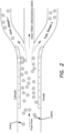
Fig. 1 is a schematic illustration of a water pretreatment system for treating PFAS-contaminated water prior to passage through a SCWO reactor. -
Fig. 2 schematically illustrates separation in an electric field. -
Fig. 3 is a drawing of laboratory scale apparatus that was used to remove salt from solution. -
Fig. 4A illustrates a tube-in-tube heat exchanger.Fig. 4B is a cut-away view of the heat exchanger. -
Fig. 5 illustrates a system for handling corrosive effluent containing aqueous HF at high temperature. -
Fig. 6A illustrates a SCWO system for the oxidation of PFAS. -
Fig. 6B illustrates a compact SCWO system for the oxidation of PFAS. -
Fig. 7 illustrates the confirmation of the test reactor used in the examples. -
Fig. 8 shows the results of a SCWO destruction of a PFAS sample. -
Fig. 9 shows the results of a SCWO destruction of a PFAS field sample. -
Fig. 10 schematically illustrates a SCWO reactor with a curved wall in a transpiring transpiring wall reactor. -
Fig. 11 illustrates a spray drying system for removing solids. - According to the present invention, PFAS-contaminated water has the conventional meaning. The source of the PFAS-contaminated water can be from soil or surface or underground water in areas subjected to PFAS contamination. These areas can be industrial areas, especially where water-proofing or non-stick coatings have been applied. Another common source of PFAS-contaminated water is in areas around airfields or firefighting training areas that have been exposed to AFFF (aqueous film forming foam). Another source can be storage vessels, typically these are accumulated for future destruction or disposal. Typically, there will be non-fluorinated organic compounds present in PFAS-contaminated water and, especially in AFFF residue, there can be chlorinated or brominated compounds.
- Debris and other solids can be removed from the PFAS-contaminated water prior destruction of the PFAS. Typically, this can be accomplished by one or a plurality of filtration steps. In some embodiments, a plurality of filtration steps can be conducted in which increasingly smaller particles are removed. The filters can be valved so that only one or a series of filters can be utilized; for example one filter or a set of filters can be cleaned or exchanged while another filter or set of filters continue to operate. Filters can be any type of filter known for filtering water such as bag filters, cartridge filters, metal screen or sand (preferably silica sand). Alternatively, or in addition, centrifugal separation can be used to remove solids.
- The PFAS-contaminated water can be subjected to a softening treatment. These softening treatments may include one or any combination of the following: ion exchange resin, lime softening (aqueous calcium hydroxide to precipitate solids); chelating agents (for example, treatment with EDTA or the like); and reverse osmosis. Reverse osmosis is a preferred treatment for pretreatment. In any pretreatment, capture of PFAS in pretreatment media should be considered. Alternatively, or in addition, compounds such as organics can be removed by passage through hydrophobic clay to remove emulsified oils and granular activated carbon; both of which may absorb PFAS so this use of adsorbent media in pretreatment may require additional treatment steps.
- One embodiment of a pretreatment system is illustrated in
Figure 1 . PFAS-contaminated water from source 110 (such as a feed tank) is pumped through asolids separator 112 and then throughoptional filters solids water 120 can have undesired counterions (typically Ca and Mg) removed/replaced insoftener 122. If needed, supplementalclean water 124 can be added. Alternatively, or in addition,softened water 126 orwater 120 can be passed through areverse osmosis system 128. Thesoftener 122 can be flushed and the flush water sent topurifier system 130 that may include granulated activatedcarbon 132 and then discharged or sent to an evaporation holding tank. - Reverse osmosis (RO) systems can remove or concentrate PFAS from water streams. PFAS-free (or PFAS-reduced) water travels through the membrane while the PFAS and salts are directed to a brine stream. Efficiency of PFAS removal and throughput is increased by implementing a cascade of RO membranes. In some embodiments, RO is utilized to increase the concentration of PFAS by at least 5 times or at least 10 times, and in some embodiments in the range of 5 to 30 times or 5 to 20 times.
- Separation in an electric field is another concept that can be applied to water prior to feeding to the reactor or to clean effluent, or both. This concept is schematically illustrated in
Figure 2 . A constant electric field is applied to the water. For water flowing toward the reactor inlet, water carrying the PFAS compounds of interest can be concentrated and problematic species can be removed. The effluent of some reactor processes can include heavy metal atoms that can be removed by passage of the water through the electric field. A water stream can be separated into two streams, three streams or more (preferably two or three). The electrostatic plates can be easily swapped and cleaned. - The optional concentration step can be achieved by treating a PFAS-contaminated aqueous mixture with microbubbles causing the PFAS to rise to the top of the mixture where it can be separated. A detailed description of a preferred concentration method is provided below.
- Salt from the PFAS-containing aqueous solution can be removed from the solution by spraying from a small diameter nozzle into a significantly larger volume of an expansion vessel in which water is vaporized, leaving a salt-containing stalactite on the exterior surface of the nozzle. The PFAS-containing aqueous solution can be heated through a heat exchanger, and optionally pressurized, and then passing through a small diameter needle or other nozzle with small outlet orifice or orifices and rapidly expand into a larger volume. In preferred embodiments, the conduit leading to the nozzle is jacketed and heated by an outer stream (which could be a hot recycle stream from the process). The pressure in the expansion vessel is less than, preferably at least five times, more preferably at least ten times less than in the conduit leading into the nozzle. The diameter of the nozzle orifice or orifices is preferably 2.5mm or less or 1.5 mm or less, in some embodiments 0.5 mm or less. The vapor will flow downstream where it can be condensed prior to passage into a SCWO reactor; in this fashion, clogging and/or corrosion of the SCWO reactor can be substantially reduced. Solids forming on the
nozzle 302 can be scraped off or fall off the nozzle. If necessary, solids can be removed from the vapor stream. In some embodiments, the invention includes: salt removal as part of the PFAS destruction process; the salt removal apparatus, preferably as part of a SCWO system or apparatus; and/or a salt containing PFAS attached to the nozzle. Laboratory apparatus used to remove salt from an aqueous solution is illustrated in thefigure 3 which shows asalt stalactite 304. This apparatus and its use, is a further optional aspect the present invention. - Given the surfactant properties of PFAS, they partition at the air-liquid interface and tend to concentrate at the air - water interfaces of the surface water bodies. Wave action introduces the air bubbles and results in the formation of foam. Laboratory research has demonstrated that bubbling air through PFAS-contaminated water can achieve removal of PFAS (Meng et al., Chemosphere (2018), "Efficient removal of perfluorooctane sulfonate from aqueous film-forming foam solution by aeration-foam collection.").
Dickson in US 2014/0190896 discusses the use of vigorously mixed ozone to treat industrial waste; lighter foam produced in the process is directed by a foam concentrator into a fractionate chamber. Prior art processes have issues associated with large amounts of air bubbled through the water creating large amounts of foam that is difficult to manage as well as concerns over aerosols being emitted. - In some aspects of the present invention, the combination of VAF and VECS optimizes the removal and overcomes the issues described above. The principle of VAF is to produce micro-bubbles (appearing as cloudy water) inside a treatment cell by injecting air (nitrogen and oxygen)-saturated water into the bottom of the cell that is maintained under high vacuum conditions. Once the air-saturated water enters the low-pressure environment, the water becomes supersaturated with air and thus the air would drop out of solution creating micro-bubbles. Unlike bubbling air into a tank, these bubbles would be so fine that they would essentially occupy the entire floatation chamber and would rise very slowly allowing much greater contact between air and PFAS than what could be achieved via air sparging. In addition, a very low volume of air would be introduced into the cell in comparison to what would be injected in a sparging application. This allows the PFAS to be "scrubbed" and gently floated to the top of the chamber. The treatment cell preferably has several floatation cells in series separated by baffles. The forward flow would flow via gravity from one floatation chamber to the next. The use of in-series chambers would enhance treatment efficiency. For example, if each cell achieved 75% removal of PFAS, having three chambers in series would achieve 98% removal and four cells would achieve greater than 99.5% removal.
- The air-saturated water can be generated in a simple vessel where air is bubbled through water. The water is preferably drawn from an uncontaminated source, possibly treated effluent. The air-saturated water would be drawn into the floatation chambers, as those chambers are under a vacuum, thus no pumping is needed for this water.
- The foam from each chamber would overflow into separate foam collection sections of the tank, which are under vacuum as this is all part of one enclosure. This prevents aerosols from being emitted and even if there is leakage in the tank, air would leak in rather than aerosols leaking out. The foam from the later chambers would tend to be more dilute and could be sprayed down with effluent to break the foam and then would be recycled back to the inlet of the treatment cell. The foam from the first chamber would be highly concentrated and could be sucked out from a pipe that is connected to the same vacuum pump that is used to create the vacuum for the treatment cell. A high air flow rate would be generated by recycling the air flow and this creates a high velocity that can facilitate the withdrawal of the foam. The mixture of foam and air would be sent to a cyclone air-water separator that is still under vacuum. Having the foam under vacuum will enhance foam breaking because, when under vacuum, the air bubble will become larger and less stable. Within the cyclone air-water separator, a high centrifugal force will be created as the mixture enters the separator tangentially to the cylindrical wall creating a centrifuge effect. The combination of the centrifugal force and the high vacuum helps break the foam and allow the air to separate from the concentrated PFAS solution. The air goes out the top of the separator and is drawn into the vacuum pump (e.g. a liquid ring pump). Most of the discharge of the vacuum pump is recirculated to the treatment cell to recover the foam from the cell. A small amount of air is emitted. Theoretically, the amount of air emitted would be as low as the amount of air that was dissolved into the clean water tank and injected into the bottom of the floatation chamber, which would be an extremely low volume. This small amount of air is emitted to the atmosphere but if found to be necessary, can go through a demister unit to help ensure that no entrained liquid is carried out with it. The aqueous solution in the air-water separator and out of the demister is pumped out and contained for disposal (e.g., destruction either on-site or off-site) or further concentrated (e.g., batch flocculation with settling to create a sludge). Tests using simple aeration were found to be able to achieve an enrichment factor of or 8400 (Meng et al 2018). For example, with an influent water flow rate of 378 L/min (100 gpm), the amount of waste generated would be 64,35 L (17 gallons) per day. It is possible this can be enriched further (maybe one or two more orders of magnitude depending on the influent concentration) with this process to reduce the volume more. For example, if the influent contains 1 ug/L (or 1000 parts per trillion) of PFAS and we can concentrate the solution to achieve 0.1% PFAS (or 1000 parts per million), we would achieve a million to one enrichment factor. In the example above, instead of 64,35 L (17 gallons) per day, we would produce only 197 L (52 gallons) per year. The lower volumes of water are be more amenable for on or off-site destruction methods as well as on site precipitation to create a much smaller volume of sludge.
- Regarding the cost effectiveness of this system, consider that no chemicals or media are required, and the entire process is driven mostly by a vacuum pump. The vacuum pump draws the air-saturated water in as well as recirculates the air needed to draw the foam out of the treatment cell. A small blower is needed to bubble air into the clean water tank and water needs to be pumped out of the treatment cell. The baffled tank can be custom designed and have several baffled sections. The cycle separator and demister can be commercial units. Once operational, no materials need to be consumed other than electricity for the mechanical equipment and very little waste is generated - possibly zero waste if an on-site destruction unit is used on the low volume of concentrated solution.
- In another aspect of the present invention, the use of dissolved air floatation (DAF) facilitates removal of PFAS. The principle of DAF is to produce micro-bubbles (appearing as cloudy water) inside a treatment cell by first creating what is known as white water, which is pressurized water (typically to pressures of approximately 520 kPa (75 pounds per square inch gauge [psig]) that is saturated with air (nitrogen and oxygen). Once the white water enters an atmospheric pressure environment, the water becomes supersaturated with air and thus the air drops out of solution creating micro-bubbles. Unlike bubbling air into a tank, these bubbles would be so fine that they would essentially occupy the entire floatation chamber and would rise very slowly allowing much greater contact between air and PFAS than what could be achieved via aeration/air sparging. In addition, a very low volume of air would be introduced into the cell in comparison to what would be injected in a sparging application. This allows the PFAS to be "scrubbed" and gently floated to the top of the chamber. The treatment cell preferably has several floatation cells in series separated by baffles. The forward flow would flow via gravity from one floatation chamber to the next. The use of in-series chambers will enhance the treatment efficiency. For example, if each cell achieved 75% removal of PFAS, having three chambers in series would achieve 98% removal and four cells would achieve greater than 99.5% removal.
- The white water can be generated in a pressure vessel where air is bubbled through water or it could be generating by inducing air into the outlet of a pump (e.g. centrifugal pump) either using a venturi injector or a compressor. The source of the water would typically be recycled effluent. The white water is then injected into each floatation chamber.
- The foam from the first chamber would overflow into a foam collection section of the tank where it would be given time for the foam to break down into a low volume of a concentrated PFAS solution. This first chamber is referred to as the Concentration Stage as this stage has not only the objective of removing PFAS from the forward flow but also to allow the foam that gets removed to be as highly concentrated as possible.
- Each subsequent chamber (referred to as a Polishing Stage) would have continuous skimming from the top with the skimmed water being collected and sent back to the Concentrator Stage for further concentration but these stages would also have the ability of functioning similarly as the Concentrator Stage through an operational control.
- The use of white water to create microbubbles instead of aeration/sparging results in an extremely low amount of air that emits from the surface of the water and little agitation at the water surface. This prevents aerosols from being emitted and results in more manageable foam. It also reduces energy consumption as it eliminates the need for blowers/compressors to be generating large volumes of pressurized air.
- For influent that is more highly contaminated with PFAS, greater amounts of foam from the first chamber would be produced. If necessary, an optional cyclonic separator can be applied where a vacuum pump is used to suck out foam from the foam collection vessel. A high air flow rate would be generated by recycling the air flow and this creates a high velocity that can facilitate the withdrawal of the foam. The mixture of foam and air would be sent to a cyclone air-water separator that is still under vacuum. Having the foam under vacuum will enhance foam breaking because, when under vacuum, the air bubble become larger and less stable. Within the cyclone air-water separator, a high centrifugal force is created as the mixture enters the separator tangentially to the cylindrical wall creating a centrifuge effect. The combination of the centrifugal force and the high vacuum helps break the foam and allow the air to separate from the concentrated PFAS solution. The air leaves the top of the separator and is drawn into the vacuum pump (e.g. a liquid ring pump). Most of the discharge from the vacuum pump is recirculated to the foam collection vessel for foam recovery. A small amount of air is emitted. Theoretically, the amount of air emitted would be as low as the amount of air that was entrained as part of the foam. This small amount of air is emitted to the atmosphere but if found to be necessary, can go through a demister unit to help ensure that no entrained liquid is carried out with it. If the optional cyclonic separation is necessary, consideration should be given to using a modification of this DAF technology referred to as "PFAS Removal from Water using Vacuum Air Floatation (VAF) and Vacuum Enhanced Cyclone Separation (VECS)".
- The concentrated PFAS solution is pumped out and contained for disposal (e.g., destruction either on-site or off-site) or further concentrated (e.g., evaporation). The volume of this liquid would be very low, but testing is needed to determine how low. Tests using simple aeration was found to able to be able to achieve an enrichment factor or 8400 (Meng et al 2018). For example, with an influent water flow rate of 378 L/min (100 gpm) the amount of waste generated would be 64,35 L (17 gallons) per day. It is possible this can be enriched further (maybe one or two more orders of magnitude depending on the influent concentration) with this process to reduce the volume more. For example, if the influent contains 1 ug/L (or 1000 parts per trillion) of PFAS and we can concentration the solution to achieve 0.1% PFAS (or 1000 parts per million), we would get a million to one enrichment factor. In the example above, instead of 64,35 L (17 gallons) per day, we would produce only 197 L (52 gallons) per year. The lower volumes of water are more amenable for on or off-site destruction methods as well as on site precipitation to create a much smaller volume of sludge.
- Regarding the cost effectiveness of this system, consider that no chemicals or media are required, and the entire process is driven mostly by a water pump that generates a pressure of about 520 to 690 kPa (75 to 100 psig). The baffled tank can be custom designed and have several baffled sections. Once operational, no materials need to be consumed other than electricity for the mechanical equipment and very little waste is generated - possibly zero waste if an on-site destruction unit is used on the low volume of concentrated solution.
- PFAS-containing water is preferably heated prior (typically immediately prior) to entering the reactor. Heat from the reactor is used to heat water entering the reactor. The use of a heat exchanger makes the process more energy efficient, compact and extends service life of the reactor. A tube-in-tube heat exchanger is especially desirable. We have implemented and tested the heat exchanger illustrated in
Figure 4 . - Start-up requires additional heat generated by electricity or gas to heat a thermal sink such as a sand bath. If a supplemental fuel in the feed stream is being oxidized, little or no external heat need be supplied after start up. Fuels can be any organic compounds that will easily oxidize under the conditions in the oxidation reactor. Preferred fuels include alcohols, such as methanol or isopropyl alcohol, acetone, or any other, preferably water-soluble, organic fuels.
- Alkali or alkaline earth elements can be added with the concentrated PFAS solution into the oxidation reactor. Alternatively, alkali or alkaline earth elements can be added to the effluent that exits the oxidation reactor. For example, there may be little or no alkali or alkaline earth elements added to the PFAS-contaminated aqueous mixture that enters the reactor (except for the Na that is exchanged for less desired counter ions in an optional water softening pretreatment), while the effluent is treated with a NaOH solution to neutralize the solution and convert the HF in the effluent into sodium fluoride and water. The addition of the alkali or alkaline earth elements (preferably in the form of NaOH) can be added at any point subsequent to the SCWO and preferably after the solution is no longer supercritical. The resulting basic solution can be recycled to again neutralize the effluent, preferably in a continuous process in which sodium hydroxide is added as-needed. The neutralized effluent may be passed through a heat exchanger to heat up the PFAS-contaminated aqueous mixture prior the contaminated mixture enters into the oxidation reactor; and the relatively-cooler effluent may then be recycled, released to the environment, or subjected to additional treatments either on-site or at a water treatment facility.
- Per- and Polyfluoroalkyl Substances (PFAS) are destroyed and converted to carbonates, fluoride salts and sulfates. The destruction or conversion of PFAS is achieved by the synergistic effect of temperature, pressure, addition of water, an oxidant and, optionally, an alkali or alkaline earth element (or mixtures thereof). The alkali or alkaline earth element may be added in the feed into the reactor or, preferably, into the effluent to remove HF. A compound such as CsOH, NaOH, KOH, or LiOH may be added to respectively make CsF, NaF, KF, or LiF. Ca(OH)2. A quench at the very end of the oxidation process may be added to remove HF to form NaF or CaF2 (for example). This process is essentially combustion of the organic molecules in water minus the 1) flame and 2) associated environmental contaminants that are harmful to the environment. The most notable products of the oxidation reaction are carbon dioxide and water, which are environmentally friendly. The fluoride (such as CaF2) can will be removed from the water and separated for further processing if needed. The process water can be reused for the system.
- In one preferred system according to the invention is designed to destroy PFAS at a rate of at least 100 kg or at least 200 kg per hour of PFAS, in some embodiments in the range of 100 to 500 kg per hour of PFAS. To meet throughput requirements and schedule, parallel devices can be used. Furthermore, tandem SCWO will be used to increase the reactor cross-section to amplify throughput. The system may incorporate features such as 1) multiple injection-reaction points, 2) helical reaction pathway implemented using a magnetic field, 3) "after burner" minus the flame. In the traditional SCWO, there is only a single head injection point of PFAS loaded/organic loaded influent. The performance of SCWO can be turbo-boosted by using multi-injection points hence, increasing the operational throughput of the system by orders of magnitude. There are multiple reactive charge species produced in the reaction chamber and those are influenceable by a magnetic field and can be focused or diffused depending on the need to ensure frequency of interaction or reaction cross-section is amplified. The after-burner is a SCWO configuration that allows further treatment of effluent prior to cooling if additional destruction efficiency is required.
- The device can be designed for 1) stationery applications or 2) transportation to a site. The stationery configuration can be employed at a permanent processing plant such as in a permanently installed water facility such as city water treatment systems. The portable units can be used in areas of low loading requirement where temporary structures are adequate. A portable unit is sized to be transported by a semi-truck or smaller enclosed space such as a trailer or shipping container.
- The design is adaptable to processing other organic contaminants by modifying operational parameters but without modification of the device.
- The interior surfaces of the reactor can be coated with corrosion resistant materials such as platinum aluminide, B4C (boron carbide), SiC (silicon carbide), TaC (tantalum carbide), WC (tungsten carbide), metal fluorides such as YF3 (yttrium fluoride), YN (yttrium nitride), LaF3 (lanthanum fluoride), LaN (lanthanum nitride), YbN, YbF3, or any lanthanide nitride or lanthanide fluoride, HfN (hafnium nitride), CeN (cerium nitride), CeF3 (cerium fluoride), TaN (tantalum nitride), Ta (tantalum), TaF (tantalum fluoride), ZrN (zirconium nitride), ZrF (zirconium fluoride), WC (tungsten carbide), WN (tungsten nitride), or combinations thereof.
- Alternatively or in addition, corrosion can be reduced by use of a sacrificial electrode or impressed current cathodic protection.
- The SCWO system operates by raising the feed temperature and raising the feed pressure. The increased pressure can be due solely due to the heating (which is preferably) or can be further increased via a compressor or a high pressure (reciprocating) pump. The temperature is increased by: application of heat through the conduit (in the case of a continuous reactor) or through the reaction chamber in the case of a batch reactor, and/or by the addition of fuels such as alcohols that will be oxidized to generate heat in solution. Supercritical conditions are maintained for the oxidation; conditions within the reaction conduit or reaction chamber are preferably in the range of 374°C - 1200 °C and at least 220 bar, more preferably 221 - 300 bar. In some embodiments, temperature in the SCWO reactor is maintained at 500 °C or more, or 600 °C or more and in the range of 500 or 600 to 700 °C or 800 °C.
- A key step in the inventive processes is the handling of fluorine. HF (hydrofluoric acid) is corrosive and toxic and cannot be released into the environment.
- The expected full-oxidation reaction for PFOA is:

- An alternative reaction or additional reaction is to add CsOH+NaOH or KOH+LiOH to the input to balance the ions and avoid HF.
- CsF, NaF, KF, and LiF are salts that are more environmentally friendly than HF
Example:
- These salt combinations were carefully chosen because they have eutectic points below the temperature of our reactor, so the fluid travels through as molten material instead of as solid, an undesired fluid physical state. For example:
- CsF-NaF, 23.5 mol% NaF to total salt mixture - Eutectic Point 609°C
- KF-LiF, 50mol% KF to total salt mixture - Eutectic Point 485°C
- These salts are insoluble in supercritical water, but soluble in liquid water. A solid particulate could foul the reactor and cause it to plug.
- The corrosive effluent containing aqueous HF at high temperature (for example, around 700 °C) can flow into a mixing pipe. Cooling water, typically containing hydroxy salts, can be fed into the mixing pipe where it mixes with the corrosive effluent. The cooled effluent contains dissolved fluoride salts such as NaF. This system is illustrated in
Figure 5 . - A preferred SCWO reactor design is a continuous or semi-continuous system in which the (typically pre-treated) PFAS-containing aqueous solution is passed into a SCWO reactor. The aqueous solution is separated into a PFAS-enriched fraction and a PFAS-depleted fraction. The PFAS-depleted fraction is heated before passage into the SCWO reactor and then combined with a PFAS-depleted fraction (either the same PFAS-depleted fraction, in which case the fractions are recombined, or another PFAS-depleted fraction); by reducing the time and volume in which the PFAS-contaminated solution (which may also contain salts) is heated, corrosion can be reduced which both extends the lifetime of the apparatus, reduces contaminants such as heavy metals in the effluent, and may reduce clogging in the SCWO reactor.
- Because solids form in the SCWO reactor it is desirable for the reactor to slope downward so that solids are pulled by gravity downward and out of the reactor. In some embodiments, the flow path is straight and vertical (0°) with respect to gravity; in some embodiments, the reactor is sloped with respect to gravity, for example in the range of 5 to 70° (from vertical) or 10 to 50° or 10 to 30° or 10 to 20° and can have a bend so that flow moves in a (from vertical) or 10 to 50° or 10 to 30° or 10 to 20° and can have a bend so that flow moves in a reverse direction to provide a compact device in which flow is consistently downward with respect to gravity. Preferably, the reactor vessel is a cylindrical pipe formed of a corrosion resistant material. Desirably, the pipe has an internal diameter of at least 1 cm, preferably at least 2 cm and in some embodiments up to about 5 cm.
- Flow through the components of the SCWO apparatus at supercritical conditions should be conducted under turbulent flow (Re of at least 2000, preferably in the range of 2500 to 6000). Effluent from the SCWO reactor can flow into a salt separator under supercritical conditions.
- A
preferred system 400 is illustrated inFig. 6A . PFAS-contaminated water (feedstock) 402 enters mixingtee 404. The PFAS-contaminated water enters the tee at ambient conditions (room temperature) or relatively low temperature so that the inlet line is not corroded. In the mixing tee, the PFAS-contaminatedwater 402 is mixed with hot,clean water 406 which may be, for example, 650 °C. The combined stream is at a combined temperature. Theoxidant 426 can be in eitherstream stream 408 passes intoSCWO reactor 410 which is preferably a vertical (with respect to gravity) tube surrounded by insulation and heating means for start-up. Temperature in the SCWO reactor is preferably in the range of 500 to 700 °C. The effluent 412 passes into salt separator 414 wheresalt 416 where it can be removed manually or throughexhaust system 418 leaving the system asbrine 420.Salt 416 can be a mixture of sodium chloride, sodium fluoride, sodium sulfate, sodium nitrate or corresponding salts of other alkali or alkaline earth elements.Supernatant 422 leaves the separator and is routed through a heat exchanger 424, preferably in the direction indicated such that temperature offluid 422 is highest where theclean water 406 leaves the heat exchanger. After passing the heat exchanger,clean water stream 406 may optionally be passed throughheater 430 to heat the water preferably to 600 °C or higher. After passing through the heat exchanger,effluent 432 can leave the system and optionally be neutralized at any point after exiting the SCWO reactor. All or a portion of the effluent can also be recycled into the system and/or released into the environment or a water treatment facility. - Another reactor configuration is shown in
Fig. 6B ; this is similar to the reactor ofFig. 6A except the reactor is sloped with respect to gravity. - The two tested feedstocks of reactant oxygen used in supercritical water oxidation for destruction of PFAS are oxygen gas (O2) and hydrogen peroxide (H2O2). In addition to, or alternative to, these two chemical species, other reactant oxygen sources or oxidizing agents could be added to destroy PFAS in the oxidation reactor. Other oxidants are oxyanion species and peroxy acids. These include, but are not limited to, ferrate salts (FeO4 2-), percarbonate salts (ex. C2K2O6), permanganate salts (ex. KMnO4), potassium peroxymonosulfate (commercially known as Oxone), peroxybenzoic acid, and ozone (O3).
- Oxyanion species are a category of chemicals that includes, but is not limited to, ferrate (FeO4 2-), percarbonate (CO4 2-), permanganate (ex. MnO4 -), and Oxone. The general trend of these species is that at above ambient environmental conditions, the rate of oxygen release increases. The inventive system can operate at an elevated temperature and pressure to achieve supercritical water conditions. Under these same conditions, oxyanion species readily decompose and release their oxygen. Therefore, oxyanion species have the potential to be incorporated as a source of reactant oxygen; however, the addition of elements such as Mn introduces the possibility of formation of additional solids that can plug the reactor.
- Peroxybenzoic and other peroxy acids are generally regarded as oxidizing agents. Historically they are predominantly used to oxidize alkenes to epoxides, Baeyer-Villiger oxidation of ketones to ester and lactones, and oxidation of heteroatoms to oxides (amines to amine oxides, sulfides to sulfoxides and sulfones, selenides to selenoxides, phosphine to phosphine oxides). In the present invention, a peroxy acid has the potential to be an oxidizing agent for PFAS destruction.
- Ozone is unstable in neutral water solution and typically decomposes into O2 and another species. In this way, ozone has the potential to be the source of reactant oxygen for the inventive processes.
- The preferred oxidant is hydrogen peroxide which can be added in excess (for example an excess of at least 50% or at least 100% or in the range of 50% to 300% excess) and the excess hydrogen peroxide reacting to form dioxygen and water.
- From 0.5 to 5 or 1 to 3 or about 2 wt% organic fuel (for example, isopropyl alcohol) burns with enough energy to heat our reactor from 450°C - 600°C. At start-up we need to heat (electrically) from 20 to 450, then the IPA will ignite, burn, and heat the fluid to 600 °C (our target reactor temperature) inside the reactor. Once we have this running, we will use the heat from the reactor to pre-heat the fluid (instead of electric sand bath) so that the reaction runs isothermally at steady-state. However, the sand bath or other heat sink can be used as a heat exchanger to heat the pre-heating tubes from the reactor coil.
- The addition of fuel operates at any selected scale and flow rate. For example, if 378 L (100 gallons) of PFAS contaminated water is treated with 9,615 L (2.54 gallons) of isopropyl alcohol (density = 0.785 g/mL), then if you have 378 kL (100k gallons), it can be treated with 9615 L (2540 gallons) of IPA. Alternatively, the quantity of fuel can be calculated based on the heat required; for example, oxidation of IPA produces 1912 kJ/mol, IPA has a molecular weight of 60.1 g/mol, then if ~20 mg/mL of PFAS water is needed, then 0.64 kJ/mL of PFAS solution is required.
- We have also calculated that we could run isothermally at steady-state if the PFAS solution contained 7 wt% PFAS (well above the solubility limit, so not typically feasible). The destruction is exothermic and matches the heat we need to heat the fluid.
- PFAS in water is mixed with Hydrogen Peroxide and Calcium Oxide. The solution is mixed, and placed inside a pressure vessel maintained at high temperature (for example, at least 121°C (250°F) or at least 149°C (300°F), in some embodiments in the range of 121°C (250°F) or 149°C (300°F) to 260°C (500°F)) and a pressure of at least 2 atm, preferably at least 3 atm, for example, pressurized to 5 atmospheres with nitrogen for 3 hours. The resultant precipitate formed in the reaction vessel can be separated from the supernatant liquid. PFAS are extremely unreactive. We discovered, surprisingly, that greater than 99% destruction could be achieved at relatively mild conditions by the reaction of PFAS with a combination of aqueous hydrogen peroxide and alkali or alkaline earth elements (or high temperature and increased pressure as above). The calcium oxide is added to the reaction mixture to quench the HF formation, which results in the formation of Calcium fluoride. Thus, the invention includes the reaction of PFAS with an aqueous solution of hydrogen peroxide and calcium oxide at a temperature of at least 100 °C, preferably in the range of 120 to 200 °C, or in the range of 130 to 170 °C or 140 to 160 °C. Preferably, at least 90% or at least 95% or at least 99% of the PFAS is destroyed by the method.
- Any of the inventive processes can be characterized by one or any combination of the following. A temperature profile of heating the oxidation reactor to a temperature of at least 450 C to ignite fuel in the feed. In some preferred embodiments a PFAS-containing solution is mixed with a solution comprising 30 to 50 wt% H2O2 at a weight ratio of preferably 30:1 to 70:1 wt% ratio or in a particularly preferred embodiment approximately 50:1 PFAS solution:H2O2. In some embodiments, the PFAS-containing solution is passed through a SCWO reactor with a residence time of 20 sec or less, preferably 10 sec, or 5 sec or less, or 0.5 to 5 seconds. In reactors in which the PFAS is destroyed in supercritical conditions, the reactor volume is based on the volume comprising supercritical fluid conditions. A preferred reactor configuration is a continuous plug flow reactor. In some tests, the feed of concentrated PFAS is passed into an oxidation reactor a rate of about 50 mL/min; in some embodiments rate is controlled between 50 and 150 mL/min (at STP); this rate can be adjusted to obtain the desired conditions. The feed can include fuel and oxidant. Preferably, no external heating is required after start-up. In some embodiments, the PFAS-containing aqueous mixture (preferably after a concentration pretreatment) comprises at least 100 ppm PFOA and the method decreases the PFOA concentration by at least 106 or 107 or 108, and in some embodiments up to about 109.
- Any of these conditions may be utilized or obtained in a mobile unit.
- Input unsorted solid samples (for example, soil) with unknown particle size distributions are subjected to a fluidizing pressure of SCWO of variable flow. Controlling the flow allows for particle density inversion and separation of the soil into its granular constituents (sand, silt, clay organics). This fluidizing 'floor' will cause rapid permeation of SCW through the solid sample while sorting by size distribution based on the pressure. The 'ceiling' of the chamber will be a traditional transpiring wall of SCW to discourage salt accumulation and enable further SCW penetration by the solids.
- Curving the 'floor' and 'ceiling' areas will cause a natural pressure gradient along the angle, giving a natural decrease in fluidization pressure vs gravity without complex pressure adjustments. As particles drift in the chamber they will prefer the angular location which fluidizes them past their inversion point, naturally segregating the soil from the salts and output gases. Larger particles are exposed to longer treatment times while gas and salt are removed. Cleaned soil leaves during pressure cycles. The output of the chamber can collect salts in a brine chamber and the output gases as with a traditional TWSCW reactor. This is illustrated in
Fig. 10 in conjunction with a transpiring wall with preheated PFAS feedstock entering the reactor with gas and solution leaving toward the top and solids from the bottom. - SCWO is currently done at scale only on aqueous samples, or colloids suspended in a carrier fluid. This approach naturally treats solids without pre-sorting or water suspension. This design also scales up quickly in the dimensions and can be parallelized. Since SCWO reactors are exothermic, the entire process can be thermally and electrically self-sustaining after its initial startup. This reactor design applies to spent activated carbon, chemically contaminated stone, municipal solid waste treatment, as well as to soil samples.
- Other solutions include a traditional transpiring wall reactor, tubular reactors, reverse flow tanks, or film cooled reactors. A transpiring wall reactor can be useful for SCWO destruction of PFAS, especially solids. Transpiring wall prevents salts and acids from extended contact with reactor walls while ferrying away solids in turbulent flow.
- By applying fluidization this removes many problems in SCWO scaling. First, soil samples can be treated in large volumes at large speeds (for example, at least 10 kg/hr or at least 50 kg/hr; in some embodiments up to about 500 kg/hr or 300 kg/hr) without presorting or pretreatment. Next, fluidizing SCW greatly increases particle penetration, and preferentially penetrates smaller particle sizes more than larger ones. Contaminants such as PFAS prefer to bond to smaller soil particles, so this would enhance the destruction rate. Lastly, the use of the curved design removes hydraulic complexity from a variable fluidizing design, making the system more robust. This also provides tremendous opportunity for further innovation, such as creation of intentional turbulence in the reactor volume through time-varying fluidization pressure.
- One example of a mobile unit can be transported (and preferably operated within) a trailer. For example, the system can be transported (and optionally operated) on a trailer having dimensions of 29 feet (8.8 m) in length or less, 8 ft 6 in (2.6 m) or less width, and 13 ft 6in (4.1 m) height or less. These dimensions define preferred size of a mobile system, although workers in this area will understand that other dimensions could be utilized in a mobile unit.
- Since the oxidation process destroys essentially all of the PFAS, the treated effluent can be safely released back into the environment. In some embodiments, at least a portion of the effluent is evaporated into the air. This is safe since the PFAS has been destroyed and any remaining contaminants (such as metals, NaF, etc.) tend to have very high vapor pressure so that they do not evaporate with the water. The effluent may be subjected to treatments such as reverse osmosis and/or other treatments (Metsorb™, etc.) to remove metals or other contaminants prior to release or disposal of the effluent.
- Precipitates such as fluoride salts can be filtered or centrifuged from the effluent. PFAS-free effluent can be passed through the heat exchanger where the effluent is cooled by the PFAS-contaminated water flowing into the reactor. The effluent can be flashed and/or evaporated. Other techniques such as RO, chelation, and/or passage through sorbent can be used to remove impurities such as metals from the effluent.
- Solids can be removed by spray drying as illustrated in
Fig. 11 . Effluent can be sprayed into a stream of hot air. Water rapidly evaporates from the droplets leaving particles of dry solids. The solids can be collected in a cyclone and/or with filters. The clean effluent can be released into the air and/or the water can be condensed. - Numerous tests have been conducted using the SCWO apparatus schematically illustrated in
figure 7 . The reactor was immersed in a hot sand bed. As the solution passed through the tubing, temperature increased to 700 °C (supercritical conditions were established at around 374 °C). The oxidant solution (comprising either O2 or H2O2) was mixed with the PFAS-containing stream in the T-joint before passing through the high temperature reactor. The cleaned effluent then passed up and out of the reactor. - Testing of the SCWO process with an aqueous solution having 1700 ppm PFOA resulted in an effluent having less than 5 ppt PFOA.
- A test run (single pass through the SCWO reactor) was conducted with a sample prepared to simulate AFFF concentrations (386,000,000 ppt PFAS). After the SCWO destruction, 6 of the 8 PFAS analytes were reduced to below 5 ppt, with an overall destruction efficiency better than 99.999%. This is shown in
figure 8 . - A field sample comprising 8,600 ppt PFAS was passed through the reactor resulting in all 12 PFAS compounds reduced to below 5 ppt and an overall destruction of 99.95%. The before and after concentrations are shown in
figure 9 .
Claims (12)
- A method of destroying PFAS in a PFAS-containing aqueous mixture, comprising:subjecting the PFAS-containing aqueous mixture to a separation procedure and separating the PFAS-containing aqueous mixture into:
a PFAS-enriched fraction and a PFAS-depleted fraction;heating at least a portion of the PFAS-depleted fraction, or another PFAS-depleted fraction to a temperature of at least 300 °C to form a heated PFAS-depleted fraction;prior to a supercritical destruction phase, combining the heated PFAS-depleted fraction with the PFAS-enriched fraction to form a hot PFAS-containing aqueous mixture; and
reacting the hot PFAS-containing aqueous mixture with an oxidant under supercritical conditions in a SCWO reactor. - The method of claim 1 wherein the separation procedure comprises separating into a first salt-enriched, PFAS-enriched fraction and the salt-depleted, PFAS-depleted fraction by reverse osmosis.
- The method of claim 2 wherein the salt-depleted, PFAS-depleted fraction is heated by heat exchange with effluent from the step of reacting the hot PFAS-containing aqueous mixture with an oxidant under supercritical conditions in a SCWO reactor.
- The method of claim 3 wherein the salt-depleted fraction is heated to at least 300 °C by heat exchange with effluent from the SCWO reactor and is then further heated in a secondary heat exchange step to a temperature that is at least 100 °C higher than the highest temperature of the heat exchange step.
- The method of claim 3 wherein the salt-depleted, PFAS-depleted fraction is heated to a temperature of at least 500 °C or at least 600 °C or 600 °C to 700 °C prior to mixing in a mixing tee to form the hot PFAS-containing aqueous mixture prior to the step of reacting the hot PFAS-containing aqueous mixture with an oxidant under supercritical conditions.
- The method of any of the preceding claims wherein effluent from the SCWO reactor is treated with sodium hydroxide to form sodium fluoride.
- The method of any of the preceding wherein the SCWO reactor comprises a pipe having interior walls coated with a coating that resists corrosion by HF.
- The method of any of the preceding claims wherein the SCWO reactor comprises a pipe, and wherein the method further comprises adding a fuel to the mixture that passes through the SCWO reactor to provide heat within the reactor so that no external additional heating for the SCWO reactor is required.
- The method of any of the preceding claims wherein after leaving the reactor the effluent is treated with a solution comprising NaOH, LiOH, or KOH to produce a neutralized solution that is recycled to neutralize additional effluent.
- The method of any of the preceding claims wherein the PFAS-containing aqueous mixture comprises at least 100 ppm PFAS by weight, preferably at least 500 ppm or more preferably at least 1000 ppm PFAS that the method converts to an effluent comprising 1 ppm or less, or 0.1 ppm or less, or 0.01 ppm or less.
- The method of claim 8 comprising adding 0.5 to 5 or 1 to 3 or about 2 wt% organic fuel to the hot PFAS-containing aqueous mixture.
- The method of any of the preceding claims conducted in a mobile trailer, optionally at a contaminated site.
Priority Applications (1)
| Application Number | Priority Date | Filing Date | Title |
|---|---|---|---|
| EP25174534.5A EP4588899A3 (en) | 2019-06-28 | 2020-06-29 | Destruction of pfas via an oxidation process and apparatus suitable for transportation to contaminated sites |
Applications Claiming Priority (3)
| Application Number | Priority Date | Filing Date | Title |
|---|---|---|---|
| US201962868858P | 2019-06-28 | 2019-06-28 | |
| US201962948765P | 2019-12-16 | 2019-12-16 | |
| PCT/US2020/040196 WO2020264530A1 (en) | 2019-06-28 | 2020-06-29 | Destruction of pfas via an oxidation process and apparatus suitable for transportation to contaminated sites |
Related Child Applications (1)
| Application Number | Title | Priority Date | Filing Date |
|---|---|---|---|
| EP25174534.5A Division EP4588899A3 (en) | 2019-06-28 | 2020-06-29 | Destruction of pfas via an oxidation process and apparatus suitable for transportation to contaminated sites |
Publications (3)
| Publication Number | Publication Date |
|---|---|
| EP3990399A1 EP3990399A1 (en) | 2022-05-04 |
| EP3990399C0 EP3990399C0 (en) | 2025-05-07 |
| EP3990399B1 true EP3990399B1 (en) | 2025-05-07 |
Family
ID=71728952
Family Applications (2)
| Application Number | Title | Priority Date | Filing Date |
|---|---|---|---|
| EP20743481.2A Active EP3990399B1 (en) | 2019-06-28 | 2020-06-29 | Destruction of pfas via a supercritical oxidation process |
| EP25174534.5A Pending EP4588899A3 (en) | 2019-06-28 | 2020-06-29 | Destruction of pfas via an oxidation process and apparatus suitable for transportation to contaminated sites |
Family Applications After (1)
| Application Number | Title | Priority Date | Filing Date |
|---|---|---|---|
| EP25174534.5A Pending EP4588899A3 (en) | 2019-06-28 | 2020-06-29 | Destruction of pfas via an oxidation process and apparatus suitable for transportation to contaminated sites |
Country Status (7)
| Country | Link |
|---|---|
| US (5) | US11401180B2 (en) |
| EP (2) | EP3990399B1 (en) |
| JP (2) | JP7569335B2 (en) |
| KR (1) | KR20220024012A (en) |
| AU (2) | AU2020304684B2 (en) |
| CA (1) | CA3141768A1 (en) |
| WO (1) | WO2020264530A1 (en) |
Families Citing this family (43)
| Publication number | Priority date | Publication date | Assignee | Title |
|---|---|---|---|---|
| WO2020172132A1 (en) | 2019-02-20 | 2020-08-27 | Board Of Trustees Of Michigan State University | Electrode apparatus for creating a non-uniform electric field to remove polarized molecules in a fluid |
| EP3983342A4 (en) | 2019-06-12 | 2023-06-21 | Phosphorus Free Water Solutions, LLC | REMOVAL OF MATERIALS FROM WATER |
| US12351492B2 (en) | 2019-06-12 | 2025-07-08 | Nuquatic, Llc | Removal of materials from water |
| EP3990399B1 (en) * | 2019-06-28 | 2025-05-07 | Revive Environmental Technology, LLC | Destruction of pfas via a supercritical oxidation process |
| US20210206670A1 (en) * | 2019-09-27 | 2021-07-08 | Auburn University | Compositions and methods for removal of per- and polyfluoroalkyl substances (pfas) |
| KR20230048325A (en) | 2020-08-06 | 2023-04-11 | 바텔리 메모리얼 인스티튜트 | Salt separation and degradation of PFAS using reverse osmosis and salt separation |
| US12410071B1 (en) | 2020-10-19 | 2025-09-09 | Wm Intellectual Property Holdings, L.L.C. | System and method for removal of PFAS and other emerging contaminant micro-constituents from landfill leachate and other impacted liquids |
| CA3205137A1 (en) * | 2021-01-15 | 2022-07-21 | University Of Washington | Hydrothermal system for treatment of adsorbent regeneration byproducts |
| US12246974B2 (en) | 2021-01-20 | 2025-03-11 | Noblis, Inc. | Systems and methods of removing per- and polyfluoroalkyl substances (PFAS) with calcium oxide |
| US11401181B1 (en) | 2021-03-02 | 2022-08-02 | Phosphorus Free Water Solutions, Llc | Galvanic process for treating aqueous compositions |
| KR20230171462A (en) * | 2021-04-12 | 2023-12-20 | 클라로스 테크놀로지스 인코포레이티드 | Adsorbent and method for capture and defluorescence of perfluoro and polyalkyl substances (PFAS) |
| US20220363567A1 (en) * | 2021-05-14 | 2022-11-17 | Bonn Justin | Method to Remove and Concentrate PFAS from Water |
| WO2023279021A2 (en) * | 2021-07-01 | 2023-01-05 | Aquagga, Inc. | Pfas destruction in an alkaline, hydrothermal environment, and related methods and systems |
| WO2023287893A1 (en) * | 2021-07-13 | 2023-01-19 | Evoqua Water Technologies Llc | Removal material destruction by supercritical water oxidation for pfas removal |
| US11840471B1 (en) | 2021-12-20 | 2023-12-12 | Republic Services, Inc. | Method for removing per- and polyfluoroalkyl substances (PFAS) from waste water |
| US20250197256A1 (en) * | 2022-03-11 | 2025-06-19 | Aecom | Systems and methods for destroying per- and polyfluoroalkyl substances (pfas) using an electrochemical (ec) reactor |
| AU2023236012A1 (en) * | 2022-03-14 | 2024-09-26 | Evoqua Water Technologies Llc | Pfas removal and destruction using bioreactors followed by supercritical water oxidation |
| AU2023250662A1 (en) * | 2022-04-05 | 2024-11-14 | Revive Environmental Technology, Llc | Preventing hydrogen embrittlement during supercritical water oxidation (scwo) of pfas |
| US20230373824A1 (en) * | 2022-05-21 | 2023-11-23 | Revive Environmental Technology, Llc | Destruction of Perfluorosulfonic Acids (PFSAs) via Supercritical Water Oxidation |
| US20230382776A1 (en) * | 2022-05-24 | 2023-11-30 | Mycelx Technologies Corporation | Composition, method for production, and use of modified granular media for removal of pfas (per- and poly-fluoroalkyl substances) and their weathering products |
| WO2024010617A1 (en) * | 2022-07-05 | 2024-01-11 | Evoqua Water Technologies Llc | Use of supercritical carbon dioxide for sorbent extraction |
| CA3266469A1 (en) | 2022-09-02 | 2024-03-07 | Streamgo Water Solutions, Inc. | Improved method and system for treatment of pfas contaminated wastewater and other contaminants utilizing nano-aeration foam fractionation |
| GB2623573A (en) * | 2022-10-21 | 2024-04-24 | Clean Thermodynamic Energy Conv Ltd | Waste processing system and method |
| US20240189877A1 (en) * | 2022-12-09 | 2024-06-13 | Uop Llc | Processes for removing perfluoroalkyl substances and regenerating an adsorbent used with same |
| WO2024211729A1 (en) | 2023-04-05 | 2024-10-10 | Nuquatic, Llc | Removal of fluoro alkyl compounds from water using galvanic cell |
| EP4688667A2 (en) | 2023-04-05 | 2026-02-11 | NuQuatic, LLC | Treatment of aqueous composition with metal component |
| US20240336510A1 (en) * | 2023-04-06 | 2024-10-10 | Uop Llc | Processes and apparatuses for converting poly- and perfluoroalkyl substances |
| US20240336511A1 (en) * | 2023-04-06 | 2024-10-10 | Uop Llc | Processes and apparatuses for converting poly- and perfluoroalkyl substances |
| WO2024249535A1 (en) * | 2023-05-29 | 2024-12-05 | Revive Environmental Technology, Llc | Parallel supercritical water oxidation (scwo) reactors with external heating and methods of destroying pfas |
| US20240400418A1 (en) * | 2023-06-02 | 2024-12-05 | Batelle Memorial Institute | Systems and methods for foam fractionation with gas |
| US12545601B2 (en) | 2023-07-14 | 2026-02-10 | Claros Technologies Inc. | Methods and systems of photosensitizer recovery for improved PFAS destruction |
| US12534390B2 (en) | 2023-07-14 | 2026-01-27 | Claros Technologies Inc. | Methods and systems of nitrate removal in aqueous systems for improved PFAS destruction |
| US12351498B2 (en) | 2023-07-14 | 2025-07-08 | Claros Technologies Inc. | Methods and systems of PFAS destruction using UV irradiation at 222 nanometers |
| US20250050156A1 (en) * | 2023-08-07 | 2025-02-13 | Uop Llc | Processes and apparatuses for converting poly- and perfluoroalkyl substances |
| AU2024350931A1 (en) * | 2023-09-30 | 2026-01-22 | Battelle Memorial Institute | Systems and methods for treatment of contaminated foam streams using reactive metal oxides |
| AU2024352383A1 (en) * | 2023-09-30 | 2026-01-22 | Battelle Memorial Institute | Systems and methods for utilizing foam fractionation for contaminate destruction |
| AU2024364421A1 (en) * | 2023-10-17 | 2026-04-30 | Perma-Fix Environmental Services, Inc. | System and method for treating and disposing of fluorinated materials |
| WO2025090734A1 (en) * | 2023-10-24 | 2025-05-01 | L'air Liquide, Societe Anonyme Pour L'etude Et L'exploitation Des Procedes Georges Claude | Method for removal of contaminants from water and resource recovery through use of colloidal gas aphrons |
| WO2025128511A1 (en) * | 2023-12-11 | 2025-06-19 | The Regents Of The University Of California | Pretreatment methods for pfas degradation |
| NL2036507B1 (en) * | 2023-12-13 | 2025-06-20 | S T I B V | Method for removing per- and polyfluoroalkyl substances (pfas) from an aqueous stream, device, and system for removing said pfas |
| WO2025150449A1 (en) * | 2024-01-09 | 2025-07-17 | 東京エレクトロン株式会社 | Processing device and processing method |
| TW202545832A (en) * | 2024-01-25 | 2025-12-01 | 美商祿幕斯科技有限責任公司 | Integration of wet air oxidation and electro-oxidation methods for the destruction of per- and polyfluorinated alkyl substances (pfas) |
| WO2025217656A2 (en) * | 2024-12-27 | 2025-10-16 | Shaw Industries Group, Inc. | Methods of detecting perfluoroalkyl or polyfluoroalkyl substances |
Family Cites Families (100)
| Publication number | Priority date | Publication date | Assignee | Title |
|---|---|---|---|---|
| DE2640603B2 (en) * | 1976-09-09 | 1978-10-19 | Bayer Ag, 5090 Leverkusen | Process for the wet oxidation of organic substances |
| US4543190A (en) * | 1980-05-08 | 1985-09-24 | Modar, Inc. | Processing methods for the oxidation of organics in supercritical water |
| US4338199A (en) * | 1980-05-08 | 1982-07-06 | Modar, Inc. | Processing methods for the oxidation of organics in supercritical water |
| US4898107A (en) | 1985-12-26 | 1990-02-06 | Dipac Associates | Pressurized wet combustion of wastes in the vapor phase |
| US4861497A (en) | 1988-03-18 | 1989-08-29 | Welch James F | Method for the processing of organic compounds |
| US5232604A (en) * | 1990-01-31 | 1993-08-03 | Modar, Inc. | Process for the oxidation of materials in water at supercritical temperatures utilizing reaction rate enhancers |
| DE4132915C1 (en) | 1991-10-04 | 1993-04-15 | Gerd Prof. Dr.-Ing. 2100 Hamburg De Brunner | |
| US5372725A (en) | 1991-11-04 | 1994-12-13 | Halff; Albert H. | Method for separation and removal of impurities from liquids |
| US5531865A (en) * | 1992-08-19 | 1996-07-02 | Cole; Leland G. | Electrolytic water purification process |
| EP0612697B1 (en) | 1993-02-24 | 1998-01-21 | Sulzer Chemtech AG | Purification of salt containing waste water by wet oxidation at supercritical conditions |
| US5384051A (en) * | 1993-02-05 | 1995-01-24 | Mcginness; Thomas G. | Supercritical oxidation reactor |
| US5409617A (en) | 1993-07-13 | 1995-04-25 | Sri International | Environmentally acceptable waste disposal by conversion of hydrothermally labile compounds |
| US5698750A (en) * | 1994-03-07 | 1997-12-16 | Commodore Laboratories, Inc. | Methods for purifying and recovering contaminated refrigerants with aqueous solutions of bases |
| US5565616A (en) | 1994-05-09 | 1996-10-15 | Board Of Regents, The University Of Texas System | Controlled hydrothermal processing |
| US5571423A (en) * | 1994-10-14 | 1996-11-05 | Foster Wheeler Development Corporation | Process and apparatus for supercritical water oxidation |
| US6129991A (en) | 1994-10-28 | 2000-10-10 | Howmet Research Corporation | Aluminide/MCrAlY coating system for superalloys |
| US5492634A (en) * | 1995-02-02 | 1996-02-20 | Modar, Inc. | Method for treating halogenated hydrocarbons prior to hydrothermal oxidation |
| US5785868A (en) | 1995-09-11 | 1998-07-28 | Board Of Regents, Univ. Of Texas System | Method for selective separation of products at hydrothermal conditions |
| US5837149A (en) | 1996-03-22 | 1998-11-17 | Sri International | Method for hot and supercritical water oxidation of material with addition of specific reactants |
| US6010632A (en) | 1996-03-22 | 2000-01-04 | Sri International | Hydrothermal oxidation of organic compounds with heterogenous neutralizing reagent |
| US5746926A (en) * | 1996-03-22 | 1998-05-05 | Sri International | Method for hydrothermal oxidation of halogenated organic compounds with addition of specific reactants |
| US6017460A (en) * | 1996-06-07 | 2000-01-25 | Chematur Engineering Ab | Heating and reaction system and method using recycle reactor |
| JP3583606B2 (en) * | 1998-02-17 | 2004-11-04 | オルガノ株式会社 | Supercritical water oxidation method and reactor |
| US6118039A (en) | 1998-03-26 | 2000-09-12 | Battelle Memorial Institute | Method for digesting a nitro-bearing explosive compound |
| US6030587A (en) | 1998-05-11 | 2000-02-29 | Haroldsen; Brent Lowell | Method and apparatus for waste destruction using supercritical water oxidation |
| US6303844B1 (en) | 1998-12-09 | 2001-10-16 | Taiheiyo Cement Corporation | Method of decontaminating medium containing polychlorinated biphenyls or dioxins |
| KR100403412B1 (en) * | 1999-01-07 | 2003-10-30 | 니폰 쇼쿠바이 컴파니 리미티드 | Method for treating waste water |
| US7229550B2 (en) * | 1999-04-23 | 2007-06-12 | Haase Richard A | Potable water treatment system and apparatus |
| SE518803C2 (en) | 1999-09-03 | 2002-11-26 | Chematur Eng Ab | Method and reaction system with high pressure and high temperature suitable for supercritical water oxidation |
| US6288289B1 (en) * | 2000-01-27 | 2001-09-11 | Noram Engineering And Constructors Ltd. | Integrated effluent treatment process for nitroaromatic manufacture |
| JP2001239277A (en) | 2000-02-29 | 2001-09-04 | Nippon Shokubai Co Ltd | Method of processing waste water containing organic halogen compound |
| FR2814967B1 (en) | 2000-10-10 | 2003-11-14 | Commissariat Energie Atomique | METHOD AND DEVICE FOR SUPERCRITICAL WATER OXIDATION OF MATERIALS |
| US6475396B1 (en) | 2000-11-14 | 2002-11-05 | Hydroprocessing, Llc | Apparatus and method for applying an oxidant in a hydrothermal oxidation process |
| DE10061386A1 (en) | 2000-12-09 | 2002-09-05 | Daimler Chrysler Ag | Method and device for supercritical wet oxidation |
| DE10061388A1 (en) | 2000-12-09 | 2002-06-20 | Daimler Chrysler Ag | Method and device for supercritical wet oxidation |
| SE518051C2 (en) | 2000-12-14 | 2002-08-20 | Stora Kopparbergs Bergslags Ab | Ways to recycle inorganic material from decolorization sludge |
| US20020086150A1 (en) | 2000-12-28 | 2002-07-04 | Hazlebeck David A. | System and method for hydrothermal reactions-two layer liner |
| SE0102222D0 (en) | 2001-06-21 | 2001-06-21 | Chematur Eng Ab | Process and plant for treatment of waste |
| US20030146310A1 (en) | 2001-08-17 | 2003-08-07 | Jackson David P. | Method, process and apparatus for high pressure plasma catalytic treatment of dense fluids |
| US6984768B2 (en) * | 2002-05-21 | 2006-01-10 | Battelle Energy Alliance, Llc | Method for destroying halocarbon compositions using a critical solvent |
| US6875902B2 (en) * | 2002-11-06 | 2005-04-05 | National Institute Of Advanced Industrial Science And Technology | Method decomposing fluorine-containing organic material |
| US7186345B2 (en) | 2003-05-06 | 2007-03-06 | Engineered Support Systems, Inc. | Systems for water purification through supercritical oxidation |
| US7495145B1 (en) * | 2004-01-15 | 2009-02-24 | The United States Of America As Represented By The Secretary Of The Army | Reactors and methods for oxidizing chemical or biological materials |
| SE528693C2 (en) | 2004-07-02 | 2007-01-23 | Chematur Eng Ab | Process and system for producing precipitated calcium carbonate |
| FR2874513B1 (en) | 2004-08-25 | 2006-11-03 | Commissariat Energie Atomique | DIPOSITIVE AND PLANT FOR INJECTING PARTICULATE MATERIALS IN AN ENCLOSURE AND ASSOCIATED METHOD. |
| DE102004041997A1 (en) * | 2004-08-31 | 2006-03-09 | Umicore Ag & Co. Kg | Process for recycling fuel cell components |
| US7722823B2 (en) | 2004-10-22 | 2010-05-25 | Drs Sustainment Systems, Inc. | Systems and methods for air purification using supercritical water oxidation |
| GB0621968D0 (en) | 2006-11-03 | 2006-12-13 | Invista Technologies S O R L | Oxidation reactions-II |
| DE102007002056B4 (en) | 2007-01-13 | 2008-09-11 | Forschungszentrum Karlsruhe Gmbh | Method and device for converting biomass into gaseous products |
| TW200902526A (en) * | 2007-04-24 | 2009-01-16 | Shionogi & Amp Co Ltd | Aminodihydrothiazin derivative substituted with a cyclic group |
| US7812211B2 (en) | 2007-07-05 | 2010-10-12 | King Saud University | Process for the destruction of halogenated hydrocarbons and their homologous/analogous in deep eutectic solvents at ambient conditions |
| GB0812669D0 (en) | 2008-07-11 | 2008-08-20 | Kinney John | Method and apparatus for generating power from biomass |
| JP2010022961A (en) | 2008-07-22 | 2010-02-04 | Sharp Corp | Water treatment apparatus and method |
| US8017089B2 (en) * | 2008-07-25 | 2011-09-13 | Eau-Viron Incorporated | Method and apparatus for conducting supercritical wet oxidation reactions contained within a fluid envelope |
| JP5256002B2 (en) | 2008-11-25 | 2013-08-07 | オルガノ株式会社 | Wastewater treatment system for photoresist development wastewater |
| JP2010131478A (en) * | 2008-12-02 | 2010-06-17 | Japan Organo Co Ltd | Organic fluorine compound treatment system |
| CO6150041A1 (en) * | 2008-12-19 | 2010-04-20 | Univ Del Valle | PROCESS FOR THE DISTRIBUTION OF TOXIC WASTE BY OXIDATION IN THE PRESENCE OF WATER AND OXYGEN AND CONTINUOUS UNIT FOR THE TREATMENT OF HAZARDOUS COMPOUNDS |
| US20120042653A1 (en) * | 2009-04-28 | 2012-02-23 | Turbosystems Engineering, Inc. | Hydrothermal Power Plant |
| CN101987749B (en) | 2010-10-22 | 2012-02-01 | 西安交通大学 | Supercritical water treatment system for high-salinity organic waste water |
| WO2012145930A1 (en) | 2011-04-29 | 2012-11-01 | 同济大学 | Treatment method of persistent organic pollutant in particulates |
| CN102190363B (en) | 2011-05-12 | 2012-11-28 | 西安交通大学 | Supercritical water oxidation reactor by using auxiliary fuel for supplying heat |
| WO2012177907A1 (en) | 2011-06-22 | 2012-12-27 | Praxair Technology, Inc. | System and method for oxygen supply for wastewater treatment plant having biological treatment system and supercritical water oxidation treatment of sludge |
| EP2739576B1 (en) | 2011-08-03 | 2022-09-28 | Evocra Pty Limited | Method for treating industrial waste |
| US20130126442A1 (en) | 2011-11-17 | 2013-05-23 | General Electric Company | Methods for removing contaminants from water |
| CN102491485B (en) * | 2011-12-16 | 2013-10-02 | 湖南工业大学 | Choking cavitator for treating organic sewage |
| GB201203147D0 (en) * | 2012-02-23 | 2012-04-11 | Univ Birmingham | Reactor for substrate oxidation |
| CN102642947B (en) | 2012-04-23 | 2013-11-13 | 西安交通大学 | Supercritical water oxidization treatment system for high-salinity organic waste water |
| CN102642909B (en) | 2012-04-23 | 2013-12-11 | 西安交通大学 | Hydraulic cyclone desalting device for waste organic supercritical treatment |
| WO2014080739A1 (en) * | 2012-11-20 | 2014-05-30 | 公立大学法人大阪市立大学 | Method for hydrothermal oxidation treatment for organic halogen compound and catalyst therefor |
| FR3001156B1 (en) * | 2013-01-18 | 2016-10-21 | Commissariat Energie Atomique | HYDROTHERMAL OXIDATION DEVICE FOR TREATING MATERIAL IN A SUPERCRITICAL MEDIUM AND METHOD OF IMPLEMENTING THE SAME |
| US9694401B2 (en) | 2013-03-04 | 2017-07-04 | Kerfoot Technologies, Inc. | Method and apparatus for treating perfluoroalkyl compounds |
| US10807881B2 (en) * | 2014-05-12 | 2020-10-20 | Erick Mcwayne | Water treatment apparatus |
| CN104030427B (en) * | 2014-06-16 | 2015-07-01 | 西安交通大学 | Supercritical water oxidation treatment system for printing and dyeing wastewater and sludge |
| CN104445573B (en) | 2014-12-05 | 2016-06-08 | 王冰 | A kind of Novel supercritical Water oxidize comprehensive treating process system and treatment process |
| PL3283239T3 (en) | 2015-04-13 | 2019-07-31 | Archimede S.R.L. | INSTALLATION FOR WASTE DISPOSAL AND RELATED TO IT |
| EP3088368A1 (en) | 2015-04-29 | 2016-11-02 | SCW Systems B.V. | Apparatus for and method of processing a slurry containing organic components |
| US10143995B2 (en) | 2015-06-03 | 2018-12-04 | University Of Alaska Fairbanks | Flow-through reaction containment apparatus embodied as a monolithic block of material |
| CN204939232U (en) * | 2015-09-10 | 2016-01-06 | 新奥科技发展有限公司 | Supercritical reaction device and supercritical reaction system |
| CN205327820U (en) * | 2015-11-30 | 2016-06-22 | 无锡科莱欣机电制造有限公司 | Convenient operation's tea ceremony work divides tea -caddy with ration |
| US10737302B2 (en) * | 2015-12-16 | 2020-08-11 | Ecolab Usa Inc. | Peroxyformic acid compositions for membrane filtration cleaning |
| WO2017131972A1 (en) * | 2016-01-25 | 2017-08-03 | Oxytec Llc | Soil and water remediation method and apparatus for treatment of recalcitrant halogenated substances |
| WO2017153970A1 (en) | 2016-03-11 | 2017-09-14 | King Abdullah University Of Science And Technology | Supercritical water gasification with decoupled pressure and heat transfer modules |
| WO2017176659A1 (en) | 2016-04-08 | 2017-10-12 | Arkema Inc. | Process and system for subcritical oxidation of water-borne organic contaminants |
| EP3442911B1 (en) | 2016-04-13 | 2022-03-16 | Emerging Compounds Treatment Technologies, Inc. | A sustainable system and method for removing and concentrating per-and polyfluoroalkyl substances (pfas) from water |
| WO2017198275A1 (en) * | 2016-05-19 | 2017-11-23 | Aquarden Technologies Aps | A supercritical water oxidation reactor and process |
| CN105859440A (en) * | 2016-06-01 | 2016-08-17 | 谢晓亮 | Nutrient solution for increasing fruit setting rate of fructus forsythiae |
| US10752521B2 (en) | 2016-06-13 | 2020-08-25 | Eminus, Llc | System and method for treatment of soil and groundwater contaminated with PFAS |
| FR3060416B1 (en) * | 2016-12-16 | 2019-05-31 | Commissariat A L'energie Atomique Et Aux Energies Alternatives | REACTOR FOR THE HYDROTHERMAL OXIDATION TREATMENT OF ORGANIC MATTER IN A REACTIONAL ENVIRONMENT |
| US10370276B2 (en) | 2017-05-25 | 2019-08-06 | Xi'an Jiaotong University | Near-zero-release treatment system and method for high concentrated organic wastewater |
| US10307720B2 (en) | 2017-06-01 | 2019-06-04 | Xi'an Jiaotong University | Intermediate medium heat exchanging device for supercritical water oxidation system |
| US10688464B2 (en) | 2017-06-05 | 2020-06-23 | General Atomics | Corrosion inhibition in hydrothermal processing |
| WO2019040277A1 (en) | 2017-08-22 | 2019-02-28 | Michael Modell | Supercritical water oxidation systems for energy recovery and use thereof |
| WO2019079687A1 (en) | 2017-10-20 | 2019-04-25 | Duke University | Systems, methods, and techniques for waste processing |
| US10675664B2 (en) | 2018-01-19 | 2020-06-09 | Trs Group, Inc. | PFAS remediation method and system |
| WO2020010316A1 (en) | 2018-07-06 | 2020-01-09 | Beyond The Dome, Inc. | Supercritical oxidation of waste |
| US11577111B2 (en) | 2018-11-20 | 2023-02-14 | Colorado School Of Mines | Hydrothermal technology for decontamination and mineralization of perfluoro- and polyfluoroalkyl substance (PFAS) in wastes, concentrate solutions, and chemical stockpiles |
| WO2020125900A1 (en) | 2018-12-17 | 2020-06-25 | Aquarden Technologies Aps | Intertwined coil heat exchanger |
| CA3138551A1 (en) * | 2019-04-29 | 2020-11-05 | HMR Solutions, Inc. | Method and reagents for treating materials contaminated with mercury, pfas, or other contaminants |
| EP3990399B1 (en) * | 2019-06-28 | 2025-05-07 | Revive Environmental Technology, LLC | Destruction of pfas via a supercritical oxidation process |
| KR20230048325A (en) * | 2020-08-06 | 2023-04-11 | 바텔리 메모리얼 인스티튜트 | Salt separation and degradation of PFAS using reverse osmosis and salt separation |
-
2020
- 2020-06-29 EP EP20743481.2A patent/EP3990399B1/en active Active
- 2020-06-29 AU AU2020304684A patent/AU2020304684B2/en active Active
- 2020-06-29 KR KR1020217040727A patent/KR20220024012A/en active Pending
- 2020-06-29 US US16/916,085 patent/US11401180B2/en active Active
- 2020-06-29 CA CA3141768A patent/CA3141768A1/en active Pending
- 2020-06-29 EP EP25174534.5A patent/EP4588899A3/en active Pending
- 2020-06-29 JP JP2021569997A patent/JP7569335B2/en active Active
- 2020-06-29 WO PCT/US2020/040196 patent/WO2020264530A1/en not_active Ceased
-
2022
- 2022-07-23 US US17/871,907 patent/US11780753B2/en active Active
- 2022-11-21 US US17/991,124 patent/US12091331B2/en active Active
- 2022-11-21 US US17/990,765 patent/US11970409B2/en active Active
-
2024
- 2024-06-28 JP JP2024105646A patent/JP7726608B2/en active Active
- 2024-09-02 US US18/822,354 patent/US20250083978A1/en active Pending
-
2025
- 2025-10-08 AU AU2025248652A patent/AU2025248652B2/en active Active
Also Published As
| Publication number | Publication date |
|---|---|
| US20230227336A1 (en) | 2023-07-20 |
| WO2020264530A1 (en) | 2020-12-30 |
| CA3141768A1 (en) | 2020-12-30 |
| KR20220024012A (en) | 2022-03-03 |
| EP3990399C0 (en) | 2025-05-07 |
| US12091331B2 (en) | 2024-09-17 |
| JP7726608B2 (en) | 2025-08-20 |
| AU2020304684B2 (en) | 2025-07-10 |
| US11970409B2 (en) | 2024-04-30 |
| JP7569335B2 (en) | 2024-10-17 |
| US20250083978A1 (en) | 2025-03-13 |
| US20230227335A1 (en) | 2023-07-20 |
| EP3990399A1 (en) | 2022-05-04 |
| EP4588899A3 (en) | 2025-09-03 |
| US20200407241A1 (en) | 2020-12-31 |
| US20230049247A1 (en) | 2023-02-16 |
| AU2020304684A1 (en) | 2021-12-16 |
| US11780753B2 (en) | 2023-10-10 |
| AU2025248652B2 (en) | 2025-11-27 |
| US11401180B2 (en) | 2022-08-02 |
| EP4588899A2 (en) | 2025-07-23 |
| JP2022537895A (en) | 2022-08-31 |
| JP2024114932A (en) | 2024-08-23 |
| AU2025248652A1 (en) | 2025-10-30 |
Similar Documents
| Publication | Publication Date | Title |
|---|---|---|
| AU2025248652B2 (en) | Destruction of PFAS Via an Oxidation Process and Apparatus Suitable for Transportation to Contaminated Sites | |
| US12371358B2 (en) | Salt separation and destruction of PFAS utilizing reverse osmosis and salt separation | |
| JP3987646B2 (en) | Hydrothermal reaction treatment method and hydrothermal reaction treatment vessel | |
| JPH08503411A (en) | Process of oxidizing substances in water at supercritical temperature using reaction rate enhancer | |
| US20240417291A1 (en) | Pretreatments to Contaminated Water Prior to Hydrothermal or Supercritical Water Oxidation Destruction of PFAS | |
| WO2024108066A1 (en) | Pretreatment of pfas-contaminated water prior to pfas destruction | |
| Cirjan | Innovative Treatment Solutions for Oil Polluted Water | |
| JP2002126712A (en) | Method and apparatus for treating dioxins | |
| AU2023250662A1 (en) | Preventing hydrogen embrittlement during supercritical water oxidation (scwo) of pfas | |
| JP3036077B2 (en) | Method and apparatus for oxidizing organic substances together with inorganic substances under supercritical water | |
| AU2024352383A1 (en) | Systems and methods for utilizing foam fractionation for contaminate destruction |
Legal Events
| Date | Code | Title | Description |
|---|---|---|---|
| STAA | Information on the status of an ep patent application or granted ep patent |
Free format text: STATUS: UNKNOWN |
|
| STAA | Information on the status of an ep patent application or granted ep patent |
Free format text: STATUS: THE INTERNATIONAL PUBLICATION HAS BEEN MADE |
|
| PUAI | Public reference made under article 153(3) epc to a published international application that has entered the european phase |
Free format text: ORIGINAL CODE: 0009012 |
|
| STAA | Information on the status of an ep patent application or granted ep patent |
Free format text: STATUS: REQUEST FOR EXAMINATION WAS MADE |
|
| 17P | Request for examination filed |
Effective date: 20220128 |
|
| AK | Designated contracting states |
Kind code of ref document: A1 Designated state(s): AL AT BE BG CH CY CZ DE DK EE ES FI FR GB GR HR HU IE IS IT LI LT LU LV MC MK MT NL NO PL PT RO RS SE SI SK SM TR |
|
| DAV | Request for validation of the european patent (deleted) | ||
| DAX | Request for extension of the european patent (deleted) | ||
| STAA | Information on the status of an ep patent application or granted ep patent |
Free format text: STATUS: EXAMINATION IS IN PROGRESS |
|
| 17Q | First examination report despatched |
Effective date: 20230309 |
|
| P01 | Opt-out of the competence of the unified patent court (upc) registered |
Effective date: 20230615 |
|
| RAP1 | Party data changed (applicant data changed or rights of an application transferred) |
Owner name: REVIVE ENVIRONMENTAL TECHNOLOGY, LLC |
|
| GRAP | Despatch of communication of intention to grant a patent |
Free format text: ORIGINAL CODE: EPIDOSNIGR1 |
|
| STAA | Information on the status of an ep patent application or granted ep patent |
Free format text: STATUS: GRANT OF PATENT IS INTENDED |
|
| INTG | Intention to grant announced |
Effective date: 20241205 |
|
| RIN1 | Information on inventor provided before grant (corrected) |
Inventor name: MILLER, MICHAEL M. Inventor name: SCHEITLIN, CHRISTOPHER GORDON Inventor name: FRANK, AARON Inventor name: ARGUMEDO, DARWIN Inventor name: HENDRY, DOUG Inventor name: BROWN, KEITH Inventor name: JAMES, JOSHUA Inventor name: HOLLEY, DAVID Inventor name: WINECKI, SLAWOMIR Inventor name: CASCIANO, JOSEPH Inventor name: TALLARICO, JOHN Inventor name: BRYANT, NATHAN Inventor name: GARBARK, DAN Inventor name: SIRABIAN, RUSSELL R. Inventor name: DASU, KAVITHA Inventor name: DEJARME, LINDY E. Inventor name: ELLIS, JEFFREY |
|
| GRAS | Grant fee paid |
Free format text: ORIGINAL CODE: EPIDOSNIGR3 |
|
| GRAA | (expected) grant |
Free format text: ORIGINAL CODE: 0009210 |
|
| STAA | Information on the status of an ep patent application or granted ep patent |
Free format text: STATUS: THE PATENT HAS BEEN GRANTED |
|
| AK | Designated contracting states |
Kind code of ref document: B1 Designated state(s): AL AT BE BG CH CY CZ DE DK EE ES FI FR GB GR HR HU IE IS IT LI LT LU LV MC MK MT NL NO PL PT RO RS SE SI SK SM TR |
|
| REG | Reference to a national code |
Ref country code: GB Ref legal event code: FG4D |
|
| REG | Reference to a national code |
Ref country code: CH Ref legal event code: EP |
|
| REG | Reference to a national code |
Ref country code: DE Ref legal event code: R096 Ref document number: 602020050846 Country of ref document: DE |
|
| REG | Reference to a national code |
Ref country code: IE Ref legal event code: FG4D |
|
| U01 | Request for unitary effect filed |
Effective date: 20250522 |
|
| P04 | Withdrawal of opt-out of the competence of the unified patent court (upc) registered |
Free format text: CASE NUMBER: APP_25079/2025 Effective date: 20250527 |
|
| U07 | Unitary effect registered |
Designated state(s): AT BE BG DE DK EE FI FR IT LT LU LV MT NL PT RO SE SI Effective date: 20250530 |
|
| PGFP | Annual fee paid to national office [announced via postgrant information from national office to epo] |
Ref country code: GB Payment date: 20250618 Year of fee payment: 6 |
|
| U20 | Renewal fee for the european patent with unitary effect paid |
Year of fee payment: 6 Effective date: 20250728 |
|
| PG25 | Lapsed in a contracting state [announced via postgrant information from national office to epo] |
Ref country code: ES Free format text: LAPSE BECAUSE OF FAILURE TO SUBMIT A TRANSLATION OF THE DESCRIPTION OR TO PAY THE FEE WITHIN THE PRESCRIBED TIME-LIMIT Effective date: 20250507 |
|
| PG25 | Lapsed in a contracting state [announced via postgrant information from national office to epo] |
Ref country code: GR Free format text: LAPSE BECAUSE OF FAILURE TO SUBMIT A TRANSLATION OF THE DESCRIPTION OR TO PAY THE FEE WITHIN THE PRESCRIBED TIME-LIMIT Effective date: 20250808 Ref country code: NO Free format text: LAPSE BECAUSE OF FAILURE TO SUBMIT A TRANSLATION OF THE DESCRIPTION OR TO PAY THE FEE WITHIN THE PRESCRIBED TIME-LIMIT Effective date: 20250807 |
|
| PG25 | Lapsed in a contracting state [announced via postgrant information from national office to epo] |
Ref country code: PL Free format text: LAPSE BECAUSE OF FAILURE TO SUBMIT A TRANSLATION OF THE DESCRIPTION OR TO PAY THE FEE WITHIN THE PRESCRIBED TIME-LIMIT Effective date: 20250507 |
|
| PG25 | Lapsed in a contracting state [announced via postgrant information from national office to epo] |
Ref country code: HR Free format text: LAPSE BECAUSE OF FAILURE TO SUBMIT A TRANSLATION OF THE DESCRIPTION OR TO PAY THE FEE WITHIN THE PRESCRIBED TIME-LIMIT Effective date: 20250507 |
|
| PG25 | Lapsed in a contracting state [announced via postgrant information from national office to epo] |
Ref country code: RS Free format text: LAPSE BECAUSE OF FAILURE TO SUBMIT A TRANSLATION OF THE DESCRIPTION OR TO PAY THE FEE WITHIN THE PRESCRIBED TIME-LIMIT Effective date: 20250807 |
|
| PG25 | Lapsed in a contracting state [announced via postgrant information from national office to epo] |
Ref country code: IS Free format text: LAPSE BECAUSE OF FAILURE TO SUBMIT A TRANSLATION OF THE DESCRIPTION OR TO PAY THE FEE WITHIN THE PRESCRIBED TIME-LIMIT Effective date: 20250907 |
|
| PG25 | Lapsed in a contracting state [announced via postgrant information from national office to epo] |
Ref country code: SM Free format text: LAPSE BECAUSE OF FAILURE TO SUBMIT A TRANSLATION OF THE DESCRIPTION OR TO PAY THE FEE WITHIN THE PRESCRIBED TIME-LIMIT Effective date: 20250507 |
|
| PG25 | Lapsed in a contracting state [announced via postgrant information from national office to epo] |
Ref country code: CZ Free format text: LAPSE BECAUSE OF FAILURE TO SUBMIT A TRANSLATION OF THE DESCRIPTION OR TO PAY THE FEE WITHIN THE PRESCRIBED TIME-LIMIT Effective date: 20250507 |
|
| PG25 | Lapsed in a contracting state [announced via postgrant information from national office to epo] |
Ref country code: SK Free format text: LAPSE BECAUSE OF FAILURE TO SUBMIT A TRANSLATION OF THE DESCRIPTION OR TO PAY THE FEE WITHIN THE PRESCRIBED TIME-LIMIT Effective date: 20250507 |
|
| REG | Reference to a national code |
Ref country code: CH Ref legal event code: H13 Free format text: ST27 STATUS EVENT CODE: U-0-0-H10-H13 (AS PROVIDED BY THE NATIONAL OFFICE) Effective date: 20260127 |
|
| PG25 | Lapsed in a contracting state [announced via postgrant information from national office to epo] |
Ref country code: MC Free format text: LAPSE BECAUSE OF FAILURE TO SUBMIT A TRANSLATION OF THE DESCRIPTION OR TO PAY THE FEE WITHIN THE PRESCRIBED TIME-LIMIT Effective date: 20250507 |
|
| PLBE | No opposition filed within time limit |
Free format text: ORIGINAL CODE: 0009261 |
|
| STAA | Information on the status of an ep patent application or granted ep patent |
Free format text: STATUS: NO OPPOSITION FILED WITHIN TIME LIMIT |
|
| REG | Reference to a national code |
Ref country code: CH Ref legal event code: L10 Free format text: ST27 STATUS EVENT CODE: U-0-0-L10-L00 (AS PROVIDED BY THE NATIONAL OFFICE) Effective date: 20260318 |
|
| PG25 | Lapsed in a contracting state [announced via postgrant information from national office to epo] |
Ref country code: IE Free format text: LAPSE BECAUSE OF NON-PAYMENT OF DUE FEES Effective date: 20250629 |
|
| 26N | No opposition filed |
Effective date: 20260210 |
|
| PG25 | Lapsed in a contracting state [announced via postgrant information from national office to epo] |
Ref country code: CH Free format text: LAPSE BECAUSE OF NON-PAYMENT OF DUE FEES Effective date: 20250630 |