EP3989409A1 - Rotor for an electric machine, electric machine for driving a vehicle and vehicle - Google Patents
Rotor for an electric machine, electric machine for driving a vehicle and vehicle Download PDFInfo
- Publication number
- EP3989409A1 EP3989409A1 EP21202784.1A EP21202784A EP3989409A1 EP 3989409 A1 EP3989409 A1 EP 3989409A1 EP 21202784 A EP21202784 A EP 21202784A EP 3989409 A1 EP3989409 A1 EP 3989409A1
- Authority
- EP
- European Patent Office
- Prior art keywords
- rotor
- separating
- section
- partial
- sections
- Prior art date
- Legal status (The legal status is an assumption and is not a legal conclusion. Google has not performed a legal analysis and makes no representation as to the accuracy of the status listed.)
- Pending
Links
Images

Classifications
-
- H—ELECTRICITY
- H02—GENERATION; CONVERSION OR DISTRIBUTION OF ELECTRIC POWER
- H02K—DYNAMO-ELECTRIC MACHINES
- H02K3/00—Details of windings
- H02K3/46—Fastening of windings on the stator or rotor structure
- H02K3/52—Fastening salient pole windings or connections thereto
- H02K3/527—Fastening salient pole windings or connections thereto applicable to rotors only
-
- H—ELECTRICITY
- H02—GENERATION; CONVERSION OR DISTRIBUTION OF ELECTRIC POWER
- H02K—DYNAMO-ELECTRIC MACHINES
- H02K1/00—Details of the magnetic circuit
- H02K1/06—Details of the magnetic circuit characterised by the shape, form or construction
- H02K1/22—Rotating parts of the magnetic circuit
- H02K1/26—Rotor cores with slots for windings
- H02K1/265—Shape, form or location of the slots
-
- H—ELECTRICITY
- H02—GENERATION; CONVERSION OR DISTRIBUTION OF ELECTRIC POWER
- H02K—DYNAMO-ELECTRIC MACHINES
- H02K1/00—Details of the magnetic circuit
- H02K1/06—Details of the magnetic circuit characterised by the shape, form or construction
- H02K1/22—Rotating parts of the magnetic circuit
- H02K1/24—Rotor cores with salient poles ; Variable reluctance rotors
-
- B—PERFORMING OPERATIONS; TRANSPORTING
- B60—VEHICLES IN GENERAL
- B60L—PROPULSION OF ELECTRICALLY-PROPELLED VEHICLES; SUPPLYING ELECTRIC POWER FOR AUXILIARY EQUIPMENT OF ELECTRICALLY-PROPELLED VEHICLES; ELECTRODYNAMIC BRAKE SYSTEMS FOR VEHICLES IN GENERAL; MAGNETIC SUSPENSION OR LEVITATION FOR VEHICLES; MONITORING OPERATING VARIABLES OF ELECTRICALLY-PROPELLED VEHICLES; ELECTRIC SAFETY DEVICES FOR ELECTRICALLY-PROPELLED VEHICLES
- B60L50/00—Electric propulsion with power supplied within the vehicle
- B60L50/50—Electric propulsion with power supplied within the vehicle using propulsion power supplied by batteries or fuel cells
- B60L50/51—Electric propulsion with power supplied within the vehicle using propulsion power supplied by batteries or fuel cells characterised by AC-motors
-
- H—ELECTRICITY
- H02—GENERATION; CONVERSION OR DISTRIBUTION OF ELECTRIC POWER
- H02K—DYNAMO-ELECTRIC MACHINES
- H02K19/00—Synchronous motors or generators
- H02K19/02—Synchronous motors
- H02K19/10—Synchronous motors for multi-phase current
- H02K19/12—Synchronous motors for multi-phase current characterised by the arrangement of exciting windings, e.g. for self-excitation, compounding or pole-changing
-
- H—ELECTRICITY
- H02—GENERATION; CONVERSION OR DISTRIBUTION OF ELECTRIC POWER
- H02K—DYNAMO-ELECTRIC MACHINES
- H02K3/00—Details of windings
- H02K3/04—Windings characterised by the conductor shape, form or construction, e.g. with bar conductors
- H02K3/18—Windings for salient poles
-
- H—ELECTRICITY
- H02—GENERATION; CONVERSION OR DISTRIBUTION OF ELECTRIC POWER
- H02K—DYNAMO-ELECTRIC MACHINES
- H02K3/00—Details of windings
- H02K3/46—Fastening of windings on the stator or rotor structure
- H02K3/48—Fastening of windings on the stator or rotor structure in slots
- H02K3/487—Slot-closing devices
-
- H—ELECTRICITY
- H02—GENERATION; CONVERSION OR DISTRIBUTION OF ELECTRIC POWER
- H02K—DYNAMO-ELECTRIC MACHINES
- H02K3/00—Details of windings
- H02K3/46—Fastening of windings on the stator or rotor structure
- H02K3/50—Fastening of winding heads, equalising connectors, or connections thereto
- H02K3/51—Fastening of winding heads, equalising connectors, or connections thereto applicable to rotors only
-
- Y—GENERAL TAGGING OF NEW TECHNOLOGICAL DEVELOPMENTS; GENERAL TAGGING OF CROSS-SECTIONAL TECHNOLOGIES SPANNING OVER SEVERAL SECTIONS OF THE IPC; TECHNICAL SUBJECTS COVERED BY FORMER USPC CROSS-REFERENCE ART COLLECTIONS [XRACs] AND DIGESTS
- Y02—TECHNOLOGIES OR APPLICATIONS FOR MITIGATION OR ADAPTATION AGAINST CLIMATE CHANGE
- Y02T—CLIMATE CHANGE MITIGATION TECHNOLOGIES RELATED TO TRANSPORTATION
- Y02T10/00—Road transport of goods or passengers
- Y02T10/60—Other road transportation technologies with climate change mitigation effect
- Y02T10/70—Energy storage systems for electromobility, e.g. batteries
Definitions
- the present invention relates to a rotor for an electrical machine.
- the invention relates to an electric machine for driving a vehicle and a vehicle.
- the DE 10 2004 062 162 A1 discloses an electrical machine with a salient-pole rotor with field windings, with pole winding supports and displacement bodies being present in pole gaps.
- the displacement body is arranged on the pole winding supports and divided into a number of axial sections in the axial direction.
- separating sections of a separating device arranged between adjacent rotor limbs serve on the one hand for electrical insulation of the field windings and on the other hand for maintaining their shape during rotary operation.
- Full encapsulation of the rotor has already been proposed for mechanical stabilization against such radial forces, which is more expensive and complex.
- additional components such as reinforcement rings and fastenings using tie rods or screws, is expensive or complicated to assemble.
- the invention is based on the object of specifying an improved possibility for stabilizing a rotor during its operation.
- a rotor for an electrical machine having a rotor core with a multiplicity of rotor legs extending radially outwards; a number of field windings corresponding to the number of rotor limbs, each around one of the rotor limbs are wound; and a separating device, having a number of separating sections corresponding to the number of rotor legs, which are arranged between a respective pair of adjacent field windings and extend axially between two opposite end faces of the rotor, a first annular connecting section which connects the separating sections to one another on one of the end faces, and a second annular connecting portion connecting the partition portions of the other of the end faces to each other; wherein the separating device is formed by a first part and a second part, which are joined together by means of a positive and/or non-positive connection, the first part comprising at least the first connecting section and at least partially the separating sections, and the second part at least the second connecting section includes.
- the invention is based on the idea of at least partially functionally integrating at least the first ring-shaped connecting section and the separating sections into a first part of the separating device, and connecting this to the second part of the separating device, which includes at least the second connecting section, in a form-fitting and/or non-positive manner .
- the connection joining the first part and the second part of the separating device can be provided at a suitable point along the axial extent of the separating device or of the rotor. This makes it possible to insert the first part axially into intermediate spaces between the rotor limbs and then to connect it to the second part at a suitable point, in particular in a detachable manner. In this way, the first part achieves both a shape retention of the excitation winding and a mechanical support against radial forces that act on the end windings of the excitation winding.
- the rotor according to the invention is easy to manufacture, since the one provided according to the invention Separator several functions are integrated into one component and easy handling is made possible, which saves production minutes. At the same time, the rotor according to the invention allows a winding widening to be minimized.
- the rotor core of the rotor according to the invention can be formed by a large number of axially layered individual laminations which are non-rotatably connected to one another. Accordingly, the rotor core can also be referred to as a laminated core.
- the laminated core preferably has an axial through-opening in which, in particular, a shaft of the rotor is arranged.
- a respective rotor leg around which an excitation winding is wound can form a pole of the rotor. It is particularly preferred if each rotor limb has a pole shoe radially on the outside. The pole shoe can extend further in the circumferential direction than those areas of the rotor limb around which the field winding is wound.
- the rotor according to the invention has at least two, preferably at least four, particularly preferably at least eight rotor legs and/or at most 20, preferably at most 16, particularly preferably at most twelve, rotor legs. It is particularly preferred if the rotor has exactly eight rotor legs.
- a respective separating section is divided in the axial direction into a first partial separating section and a second partial separating section, with the first part of the separating device comprising the first partial separating section of a respective separating section and the second part of the separating device comprising the second partial separating section of a respective separating section.
- the second part of the separating device also partially includes a respective separating section, so that the second part also integrates the functions of the connecting section and the separating section.
- the separating sections are therefore each divided at a predetermined axial position.
- the connection is preferably designed as one that joins the partial separating sections of a respective separating section together.
- each partial separating section has a front end and a second end axially opposite the first end and the connection between the first part of the separating device and the second part of the separating device is formed by the second ends of the partial separating sections of a respective separating section.
- the connection is thus preferably realized at the second ends of the partial separating sections of a respective separating section, which are remote from the end faces.
- the second ends of the partial separating sections of a respective separating section preferably engage in one another. This enables high stability of the separating device even when axial forces act on it.
- the second end of one of the partial separating sections of a respective separating section has an axial first projection radially on the outside and the second end of the other of the partial separating sections of the respective separating section has an axial second projection radially on the inside.
- the projections can overlap in a predetermined axial area.
- the first projection has a first projection pointing radially inwards and the second projection has a second projection pointing radially outwards, which engages in the first projection.
- the projections can therefore overlap in a predetermined radial area. In this case, it is preferred if the first projection is axially further than the second projection.
- connection is realized by a hook structure or a hook design.
- first partial separating section and the second partial separating section of a respective separating section each extend over at least 25 percent, preferably at least 35 percent, particularly preferably at least 45 percent, of the axial extent of the field windings.
- a substantially axial, central division into the partial separating sections is therefore preferred, so that these can be guided from a respective end face, in particular with the second end first, between the exciter winding in order to form the connection at a substantially central axial position.
- a particularly high degree of integration can be achieved if the first part of the separating device is designed in one piece and/or is made of the same material.
- the second part of the separating device can be designed in one piece and/or made of the same material.
- a respective part is preferably made of plastic, in particular as a molded part.
- the separating sections have a wedge-shaped base when viewed from the end faces, with a tip of the base preferably pointing radially inwards.
- the separating sections can point radially inwards from a radial inner surface of the ring-shaped connecting section and then in particular also have a base area in the shape of a sector of a circle.
- the connecting sections preferably extend radially further outwards than the separating sections.
- the rotor can also have two termination devices which are each arranged on one of the end faces on the rotor core and each have termination elements which each extend between the rotor leg and the field winding.
- the terminating device enables the winding heads to be designed in a way that is gentle on the material, since they do not have to rest directly on the rotor core, but rather on the terminating elements axially on the outside.
- the closing elements are therefore preferably rounded off in areas wrapped with the excitation winding.
- the termination means further includes an annular body enclosing the through hole of the rotor core and from which the spacers extend radially outward.
- the annular body may extend further axially outward than the excitation winding.
- the connecting sections of the separating device rest radially on the outside on the terminating devices, in particular on a shoulder of a respective terminating element formed along the circumferential direction. As a result, a full contact surface of the connecting sections is formed on the termination device in order to achieve good support against the radial forces.
- the object on which the invention is based is also achieved by an electric machine for driving a vehicle, having a stator and a rotor according to the invention which is rotatably mounted inside the stator.
- the electrical machine is preferably designed as an electric motor.
- the electrical machine is preferably an electrically excited, in particular externally excited, synchronous machine.
- the object on which the invention is based is also achieved by a vehicle having an electric machine according to the invention, the electric machine being set up to drive the vehicle.
- the vehicle can be a battery electric vehicle (BEV) or a hybrid vehicle, for example.
- BEV battery electric vehicle
- hybrid vehicle for example.
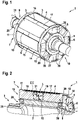
- FIG. 1 and 2 each show an embodiment of a rotor 1, wherein 1 a perspective view and 2 Fig. 12 is a cutaway perspective view.
- the rotor 1 has a rotor core 2 with a multiplicity of rotor legs 3 extending radially outwards.
- pole shoes 4 can be formed at the radial ends of the rotor limbs 3, which pole shoes widen the rotor limb 3 on both sides in the circumferential direction.
- the rotor core 2 can be designed as a laminated core. In the present exemplary embodiment, eight rotor legs 3 are provided as an example.
- the rotor 1 has a number of excitation windings 5 corresponding to the number of rotor limbs 3 , which are each wound around one of the rotor limbs 3 .
- Axial ends of the field windings 5 are also referred to as end windings 6 .
- the rotor 1 has a separating device 7 .
- the separating device 7 has a number of separating sections corresponding to the number of rotor limbs 3 8, which are arranged between a respective pair of adjacent field windings 5 and extend axially between two opposite end faces 9, 10 of the rotor 1.
- the separating device 7 has a first ring-shaped connecting section 11, which connects the separating sections 8 on one of the end faces 9, 10, here for example on the first end face 9, and a second ring-shaped connecting section 12, which connects the separating sections 8 on the other end side 9, 10, that is, here on the second end face 10, is connected to one another.
- Base areas of the separating sections 8 can, as in 1 and 2 be recognizable wedge-shaped with radially inwardly pointing tip.
- the separating device 7 is formed by a first part 13 and a second part 14 which are joined together by means of a positive and/or non-positive connection 15 .
- the connection 15 can be formed by a hook structure or a hook design.
- the first part 13 comprises the first connecting section 11 and at least partially the separating sections 8.
- the second part 14 comprises at least the second connecting section 12 and, as an example in the present exemplary embodiment, also partly the separating sections 8.
- a respective separating section can be divided in the axial direction into a first partial separating section, which belongs to the first part 13 , and into a second partial separating section 17 , which belongs to the second part 14 .
- the first partial separating section 16 can have a front first end 18 and a second end 19 axially opposite the first end 18 and the second partial separating section 17 can have a front first end 20 and a second end 21 axially opposite the first end 20 .
- the parts 13, 14 can each be made in one piece and made of the same material.
- the connecting section 11, 12 and the partial separating sections 16, 17 of a respective part 13, 14 are formed in one piece and are made of the same material.
- FIG. 3 is a detailed view of section III in 2 one of the separating sections 8 in the area of the connection 15.
- connection 15 between the first part 13 and the second part 14 of the separating device 7 can be formed by the second ends 19, 21 of the partial separating sections 16, 17 of a respective separating section 8, with the second ends 19, 21 of a respective separating section 8 preferably interlocking.
- the second end 21 of one of the partial separating sections, here the second partial separating section 17, optionally has an axial first projection 22 radially on the outside, whereas the second end 19 of the other partial separating section, i.e. the first partial separating section 16, can have an axial second projection 23 radially on the inside.
- the first projection 22 can in turn have a first projection 24 pointing radially inwards and the second projection 23 can have a second projection 25 pointing radially outwards.
- an axial length a of the first projection 24 is longer than an axial length b of the second projection 25 , so that the first projection 24 is axially longer than the second projection 25 .
- the joint 15 is formed at a substantially axial center position of the rotor core 2 . Because of the projections 22, 23, the partial separating sections 16, 17 extend over more than 50% of the axial extension of the field windings 5. However, a partition between the first partial separating section 16 and the second partial separating section 17 can also be provided at a different axial position, so that the partial separating sections 16, 17 can only extend over at least 25 percent, preferably 35 percent, particularly preferably at least 45 percent of the axial extent of the field windings 5.
- the rotor 1 optionally has two termination devices 26, 27, each on one of the end faces 9, 10 on the rotor core 2 are arranged and each have a number of closing elements 28 corresponding to the number of rotor legs 3 . These each extend between one of the rotor limbs 3 and the excitation winding 5 that wraps around it.
- the connecting sections 11, 12 of the separating device 7 can rest radially on the outside on the closing devices 26, 27. For this purpose, they can have a shoulder 30 formed along the circumferential direction on a respective closing element 28 .
- FIG. 4 1 is a schematic diagram of an exemplary embodiment of a vehicle 100, which is designed in particular as a battery electric vehicle (BEV) or as a hybrid vehicle.
- BEV battery electric vehicle
- the electrical machine 101 comprises a stator 102 and a rotor 1 rotatably mounted within the stator 102 according to the exemplary embodiment described above.
- the electrical machine 101 can be embodied as an electric motor and/or as an electrically excited, in particular externally excited, synchronous machine.
Abstract
Rotor (1) für eine elektrische Maschine (101), aufweisend― einen Rotorkern (2) mit einer Vielzahl von sich radial nach außen erstreckenden Rotorschenkeln (3);― eine der Anzahl der Rotorschenkel (3) entsprechende Anzahl von Erregerwicklungen (5), die jeweils um einen der Rotorschenkel (3) gewickelt sind; und― eine Trennvorrichtung (7), aufweisend― eine der Anzahl der Rotorschenkel (3) entsprechende Anzahl von Trennabschnitten (8), die zwischen einem jeweiligen Paar benachbarter Erregerwicklungen (5) angeordnet sind und sich axial zwischen zwei gegenüberliegenden Stirnseiten (9, 10) des Rotors (1) erstrecken,― einen ersten ringförmigen Verbindungsabschnitt (11), der die Trennabschnitte (8) an einer der Stirnseiten (9) miteinander verbindet, und― einen zweiten ringförmigen Verbindungsabschnitt (12), der die Trennabschnitte (8) der anderen der Stirnseiten (10) miteinander verbindet;wobei die Trennvorrichtung (7) durch einen ersten Teil (13) und durch einen zweiten Teil (14) ausgebildet ist, die mittels einer formschlüssigen und/oder kraftschlüssigen Verbindung (15) aneinander gefügt sind, wobei der erste Teil (13) zumindest den ersten Verbindungsabschnitt (11) und zumindest teilweise die Trennabschnitte (8) umfasst und der zweite Teil (14) zumindest den zweiten Verbindungsabschnitt (12) umfasst.Rotor (1) for an electrical machine (101), having― a rotor core (2) with a multiplicity of rotor limbs (3) extending radially outwards;― a number of field windings (5) corresponding to the number of rotor limbs (3), each wound around one of the rotor legs (3); and― a separating device (7), having― a number of separating sections (8) corresponding to the number of rotor legs (3), which are arranged between a respective pair of adjacent field windings (5) and are located axially between two opposite end faces (9, 10) of the rotor (1),― a first annular connecting section (11) which connects the separating sections (8) to one another on one of the end faces (9), and― a second annular connecting section (12) which connects the separating sections (8) of the other connecting the end faces (10) to one another; the separating device (7) being formed by a first part (13) and a second part (14), which are joined together by means of a positive and/or non-positive connection (15), the first part (13) comprises at least the first connecting section (11) and at least partially the separating sections (8) and the second part (14) comprises at least the second connecting section (12) and includes.
Description
Die vorliegende Erfindung betrifft einen Rotor für eine elektrische Maschine. Daneben betrifft die Erfindung eine elektrische Maschine zum Antreiben eines Fahrzeugs und ein Fahrzeug.The present invention relates to a rotor for an electrical machine. In addition, the invention relates to an electric machine for driving a vehicle and a vehicle.
Die
Bei Rotoren mit Rotorschenkeln, die von Erregerwicklungen umwickelt sind, dienen zwischen benachbarten Rotorschenkeln angeordnete Trennabschnitte einer Trennvorrichtung einerseits zur elektrischen Isolierung der Erregerwicklungen und andererseits zu deren Formerhaltung während eines rotatorischen Betriebs. Dabei wirken auch erhebliche Radialkräfte, insbesondere Fliehkräfte, auf stirnseitige Enden der Erregerwicklungen, die sogenannten Wickelköpfe. Zur mechanischen Stabilisierung gegenüber solchen Radialkräften wurde bereits ein Vollverguss des Rotors vorgeschlagen, was teurer und aufwendig ist. Die alternative Verwendung zusätzlicher Bauteile, wie Armierungsringe und Befestigungen mittels Zugankern oder Schrauben, ist teuer oder kompliziert zu montieren.In the case of rotors with rotor limbs around which field windings are wound, separating sections of a separating device arranged between adjacent rotor limbs serve on the one hand for electrical insulation of the field windings and on the other hand for maintaining their shape during rotary operation. Considerable radial forces, in particular centrifugal forces, also act on the front ends of the field windings, the so-called winding overhangs. Full encapsulation of the rotor has already been proposed for mechanical stabilization against such radial forces, which is more expensive and complex. The alternative use of additional components, such as reinforcement rings and fastenings using tie rods or screws, is expensive or complicated to assemble.
Der Erfindung liegt die Aufgabe zugrunde, eine verbesserte Möglichkeit zur Stabilisierung eines Rotors während seines Betriebs anzugeben.The invention is based on the object of specifying an improved possibility for stabilizing a rotor during its operation.
Diese Aufgabe wird erfindungsgemäß gelöst durch einen Rotor für eine elektrische Maschine, aufweisend einen Rotorkern mit einer Vielzahl von sich radial nach außen erstreckenden Rotorschenkeln; eine der Anzahl der Rotorschenkel entsprechende Anzahl von Erregerwicklungen, die jeweils um einen der Rotorschenkel gewickelt sind; und eine Trennvorrichtung, aufweisend eine der Anzahl der Rotorschenkel entsprechende Anzahl von Trennabschnitten, die zwischen einem jeweiligen Paar benachbarter Erregerwicklungen angeordnet sind und sich axial zwischen zwei gegenüberliegenden Stirnseiten des Rotors erstrecken, einen ersten ringförmigen Verbindungsabschnitt, der die Trennabschnitte an einer der Stirnseiten miteinander verbindet, und einen zweiten ringförmigen Verbindungsabschnitt, der die Trennabschnitte der anderen der Stirnseiten miteinander verbindet; wobei die Trennvorrichtung durch einen ersten Teil und durch einen zweiten Teil ausgebildet ist, die mittels einer formschlüssigen und/oder kraftschlüssigen Verbindung aneinander gefügt sind, wobei der erste Teil zumindest den ersten Verbindungsabschnitt und zumindest teilweise die Trennabschnitte umfasst und der zweite Teil zumindest den zweiten Verbindungsabschnitt umfasst.According to the invention, this object is achieved by a rotor for an electrical machine, having a rotor core with a multiplicity of rotor legs extending radially outwards; a number of field windings corresponding to the number of rotor limbs, each around one of the rotor limbs are wound; and a separating device, having a number of separating sections corresponding to the number of rotor legs, which are arranged between a respective pair of adjacent field windings and extend axially between two opposite end faces of the rotor, a first annular connecting section which connects the separating sections to one another on one of the end faces, and a second annular connecting portion connecting the partition portions of the other of the end faces to each other; wherein the separating device is formed by a first part and a second part, which are joined together by means of a positive and/or non-positive connection, the first part comprising at least the first connecting section and at least partially the separating sections, and the second part at least the second connecting section includes.
Die Erfindung beruht auf der Überlegung, zumindest den ersten ringförmigen Verbindungsabschnitt und die Trennabschnitte zumindest teilweise funktional in einen ersten Teil der Trennvorrichtung zu integrieren, und diesen formschlüssig und/oder kraftschlüssig mit dem zweiten Teil der Trennvorrichtung, der zumindest den zweiten Verbindungsabschnitt umfasst, zu verbinden. Die den ersten Teil und den zweiten Teil der Trennvorrichtung aneinander fügende Verbindung kann dabei an einer geeigneten Stelle entlang der axialen Erstreckung der Trennvorrichtung bzw. des Rotors vorgesehen sein. Dies ermöglicht es, den ersten Teil axial in Zwischenräume zwischen den Rotorschenkeln einzuführen und dann an geeigneter Stelle mit dem zweiten Teil, insbesondere lösbar, zu verbinden. Der erste Teil realisiert auf diese Weise sowohl eine Formerhaltung der Erregerwicklung als auch eine mechanische Abstützung gegen Radialkräfte, die auf Wickelköpfe der Erregerwicklung wirken.The invention is based on the idea of at least partially functionally integrating at least the first ring-shaped connecting section and the separating sections into a first part of the separating device, and connecting this to the second part of the separating device, which includes at least the second connecting section, in a form-fitting and/or non-positive manner . The connection joining the first part and the second part of the separating device can be provided at a suitable point along the axial extent of the separating device or of the rotor. This makes it possible to insert the first part axially into intermediate spaces between the rotor limbs and then to connect it to the second part at a suitable point, in particular in a detachable manner. In this way, the first part achieves both a shape retention of the excitation winding and a mechanical support against radial forces that act on the end windings of the excitation winding.
Wegen dieser mechanischen Stabilisierung kann die Funktion des Rotors bzw. der ihn aufweisenden elektrischen Maschine auch bei hohen mechanischen Belastungen, insbesondere bei hohen Drehzahlen, gewährleistet werden. Der erfindungsgemäße Rotor ist fertigungsfreundlich, da bei der erfindungsgemäß vorgesehenen Trennvorrichtung mehrere Funktionen in ein Bauteil integriert sind und eine einfache Handhabung ermöglicht wird, was Fertigungsminuten einspart. Gleichzeitig ermöglicht der erfindungsgemäße Rotor eine Minimierung einer Wicklungsaufweitung.Because of this mechanical stabilization, the function of the rotor or the electrical machine having it can be guaranteed even under high mechanical loads, in particular at high speeds. The rotor according to the invention is easy to manufacture, since the one provided according to the invention Separator several functions are integrated into one component and easy handling is made possible, which saves production minutes. At the same time, the rotor according to the invention allows a winding widening to be minimized.
Der Rotorkern des erfindungsgemäßen Rotors kann durch eine Vielzahl von axial geschichteten und drehfest miteinander verbundenen Einzelblechen ausgebildet sein. Der Rotorkern kann dementsprechend auch als Blechpaket bezeichnet werden. Vorzugsweise weist das Blechpaket eine axiale Durchgangsöffnung auf, in der insbesondere eine Welle des Rotors angeordnet ist. Ein jeweiliger mit einer Erregerwicklung umwickelter Rotorschenkel kann einen Pol des Rotors ausbilden. Es wird besonders bevorzugt, wenn jeder Rotorschenkel radial außen einen Polschuh aufweist. Der Polschuh kann sich in Umfangsrichtung weiter erstrecken, als solche Bereiche des Rotorschenkels, die mit der Erregerwicklung umwickelt sind. In bevorzugter Ausgestaltung weist der erfindungsgemäße Rotor wenigstens zwei, bevorzugt wenigstens vier, besonders bevorzugt wenigstens acht Rotorschenkel und/oder höchstens 20, bevorzugt höchstens 16, besonders bevorzugt höchstens zwölf, Rotorschenkel auf. Es wird besonders bevorzugt, wenn der Rotor genau acht Rotorschenkel aufweist.The rotor core of the rotor according to the invention can be formed by a large number of axially layered individual laminations which are non-rotatably connected to one another. Accordingly, the rotor core can also be referred to as a laminated core. The laminated core preferably has an axial through-opening in which, in particular, a shaft of the rotor is arranged. A respective rotor leg around which an excitation winding is wound can form a pole of the rotor. It is particularly preferred if each rotor limb has a pole shoe radially on the outside. The pole shoe can extend further in the circumferential direction than those areas of the rotor limb around which the field winding is wound. In a preferred embodiment, the rotor according to the invention has at least two, preferably at least four, particularly preferably at least eight rotor legs and/or at most 20, preferably at most 16, particularly preferably at most twelve, rotor legs. It is particularly preferred if the rotor has exactly eight rotor legs.
Es wird bei dem erfindungsgemäßen Rotor bevorzugt, wenn ein jeweiliger Trennabschnitt in axialer Richtung in einen ersten Teiltrennabschnitt, und in einen zweiten Teiltrennabschnitt aufgeteilt ist, wobei der erste Teil der Trennvorrichtung den ersten Teiltrennabschnitt eines jeweiligen Trennabschnitts umfasst und der zweite Teil der Trennvorrichtung den zweiten Teiltrennabschnitt eines jeweiligen Trennabschnitts umfasst. In diesem Fall umfasst auch der zweite Teil der Trennvorrichtung teilweise einen jeweiligen Trennabschnitt, sodass auch der zweite Teil eine Funktionsintegration von Verbindungsabschnitt und Trennabschnitt realisiert. Die Trennabschnitte sind mithin jeweils an einer vorgegebenen Axialposition aufgeteilt. Bevorzugt ist die Verbindung als eine solche, die die Teiltrennabschnitte eines jeweiligen Trennabschnitts aneinanderfügt, ausgebildet.In the rotor according to the invention, it is preferred if a respective separating section is divided in the axial direction into a first partial separating section and a second partial separating section, with the first part of the separating device comprising the first partial separating section of a respective separating section and the second part of the separating device comprising the second partial separating section of a respective separating section. In this case, the second part of the separating device also partially includes a respective separating section, so that the second part also integrates the functions of the connecting section and the separating section. The separating sections are therefore each divided at a predetermined axial position. The connection is preferably designed as one that joins the partial separating sections of a respective separating section together.
In Weiterbildung kann vorgesehen sein, dass jeder Teiltrennabschnitt ein stirnseitiges erstes Ende und ein dem ersten Ende axial gegenüberliegendes zweites Ende aufweist und die Verbindung zwischen dem ersten Teil der Trennvorrichtung und dem zweiten Teil der Trennvorrichtung durch die zweiten Enden der Teiltrennabschnitte eines jeweiligen Trennabschnitts ausgebildet ist. Die Verbindung wird somit vorzugsweise an den den Stirnseiten abgewandten zweiten Enden der Teiltrennabschnitte eines jeweiligen Trennabschnitts realisiert.In a further development it can be provided that each partial separating section has a front end and a second end axially opposite the first end and the connection between the first part of the separating device and the second part of the separating device is formed by the second ends of the partial separating sections of a respective separating section. The connection is thus preferably realized at the second ends of the partial separating sections of a respective separating section, which are remote from the end faces.
Zur Ausbildung der formschlüssigen und/oder kraftschlüssigen Verbindung greifen die zweiten Enden der Teiltrennabschnitte eines jeweiligen Trennabschnitts bevorzugt ineinander. Dies ermöglicht eine hohe Stabilität der Trennvorrichtung auch bei auf sie wirkenden Axialkräften.To form the positive and/or non-positive connection, the second ends of the partial separating sections of a respective separating section preferably engage in one another. This enables high stability of the separating device even when axial forces act on it.
Alternativ oder zusätzlich kann vorgesehen sein, dass das zweite Ende eines der Teiltrennabschnitte eines jeweiligen Trennabschnitts radial außen einen axialen ersten Vorsprung aufweist und das zweite Ende des anderen der Teiltrennabschnitte des jeweiligen Trennabschnitts radial innen ein axialen zweiten Vorsprung aufweist. Die Vorsprünge können dabei in einem vorgegebenen Axialbereich überlappen.Alternatively or additionally, it can be provided that the second end of one of the partial separating sections of a respective separating section has an axial first projection radially on the outside and the second end of the other of the partial separating sections of the respective separating section has an axial second projection radially on the inside. The projections can overlap in a predetermined axial area.
In Weiterbildung kann vorgesehen sein, dass der erste Vorsprung einen radial nach innen weisenden ersten Überstand aufweist und der zweite Vorsprung einen radial nach außen weisenden zweiten Überstand aufweist, der in den ersten Überstand eingreift. Die Überstände können mithin in einem vorgegebenen Radialbereich überlappen. Dabei wird es bevorzugt, wenn der erste Überstand axial weiter als der zweite Überstand ist.In a further development it can be provided that the first projection has a first projection pointing radially inwards and the second projection has a second projection pointing radially outwards, which engages in the first projection. The projections can therefore overlap in a predetermined radial area. In this case, it is preferred if the first projection is axially further than the second projection.
Allgemein wird es bei dem erfindungsgemäßen Rotor bevorzugt, wenn die Verbindung durch eine Hackenstruktur bzw. ein Hackendesign realisiert ist.In general, it is preferred with the rotor according to the invention if the connection is realized by a hook structure or a hook design.
Im Hinblick auf die Aufteilung der Trennabschnitte in Teiltrennabschnitte wird es bevorzugt, wenn der erste Teiltrennabschnitt und der zweite Teiltrennabschnitt eines jeweiligen Trennabschnitts sich jeweils über wenigstens 25 Prozent, bevorzugt wenigstens 35 Prozent, besonders bevorzugt wenigstens 45 Prozent, der axialen Erstreckung der Erregerwicklungen erstrecken. Es wird mithin eine im Wesentlichen axialen mittige Aufteilung in die Teiltrennabschnitte bevorzugt, sodass diese von einer jeweiligen Stirnseite, insbesondere mit dem zweiten Ende voran, zwischen die Erregerwicklung geführt werden können, um an einer im Wesentlichen mittigen Axialposition die Verbindung auszubilden.With regard to the division of the separating sections into partial separating sections, it is preferred if the first partial separating section and the second partial separating section of a respective separating section each extend over at least 25 percent, preferably at least 35 percent, particularly preferably at least 45 percent, of the axial extent of the field windings. A substantially axial, central division into the partial separating sections is therefore preferred, so that these can be guided from a respective end face, in particular with the second end first, between the exciter winding in order to form the connection at a substantially central axial position.
Ein besonders hoher Integrationsgrad kann erreicht werden, wenn der erste Teil der Trennvorrichtung einstückig und/oder materialidentisch ausgebildet ist. Alternativ oder zusätzlich kann der zweite Teil der Trennvorrichtung einstückig und/oder materialidentisch ausgebildet sein. Ein jeweiliger Teil ist dabei bevorzugt aus Kunststoff gebildet, insbesondere als Formgussteil.A particularly high degree of integration can be achieved if the first part of the separating device is designed in one piece and/or is made of the same material. Alternatively or additionally, the second part of the separating device can be designed in one piece and/or made of the same material. A respective part is preferably made of plastic, in particular as a molded part.
Insbesondere weisen bei dem erfindungsgemäßen Rotor die Trennabschnitte von den Stirnseiten aus gesehen eine keilförmige Grundfläche auf, wobei bevorzugt eine Spitze der Grundfläche radial nach innen weist. Die Trennabschnitte können von einer radialen Innenfläche des ringförmigen Verbindungsabschnitts radial nach innen weisen und dann insbesondere auch eine kreissektorförmige Grundfläche aufweisen. Außerdem erstrecken sich die Verbindungabschnitte bevorzugt radial weiter nach außen als die Trennabschnitte.In particular, in the rotor according to the invention, the separating sections have a wedge-shaped base when viewed from the end faces, with a tip of the base preferably pointing radially inwards. The separating sections can point radially inwards from a radial inner surface of the ring-shaped connecting section and then in particular also have a base area in the shape of a sector of a circle. In addition, the connecting sections preferably extend radially further outwards than the separating sections.
In vorteilhafter Weiterbildung des erfindungsgemäßen Rotors kann dieser ferner zwei Abschlussvorrichtungen aufweisen, die jeweils an einer der Stirnseiten am Rotorkern angeordnet sind und jeweils Abschlusselemente aufweist, die sich jeweils zwischen dem Rotorschenkel und der Erregerwicklung erstrecken. Die Abschlussvorrichtung ermöglicht insbesondere eine materialschonende Ausbildung der Wickelköpfe, da diese nicht direkt auf dem Rotorkern aufliegen müssen, sondern axial außen auf den Abschlusselementen. Die Abschlusselemente sind daher in mit der Erregerwicklung umwickelten Bereichen bevorzugt abgerundet ausgebildet.In an advantageous further development of the rotor according to the invention, it can also have two termination devices which are each arranged on one of the end faces on the rotor core and each have termination elements which each extend between the rotor leg and the field winding. In particular, the terminating device enables the winding heads to be designed in a way that is gentle on the material, since they do not have to rest directly on the rotor core, but rather on the terminating elements axially on the outside. The closing elements are therefore preferably rounded off in areas wrapped with the excitation winding.
Vorzugsweise umfasst die Abschlussvorrichtungen ferner einen ringförmigen Körper, der die Durchgangsöffnung des Rotorkerns umschließt und von dem sich die Abstandselemente radial nach außen erstrecken. Der ringförmige Körper kann sich axial weiter nach außen erstrecken als die Erregerwicklung.Preferably, the termination means further includes an annular body enclosing the through hole of the rotor core and from which the spacers extend radially outward. The annular body may extend further axially outward than the excitation winding.
In bevorzugter Ausgestaltung ist vorgesehen, dass die Verbindungsabschnitte der Trennvorrichtung radial außen auf den Abschlussvorrichtungen, insbesondere auf einem entlang der Umfangsrichtung ausgebildeten Absatz eines jeweiligen Abschlusselements, aufliegen. Dadurch wird eine satte Auflagefläche der Verbindungabschnitte auf der Abschlussvorrichtungen ausgebildet, um eine gute Abstützung gegen die Radialkräfte zu erzielen.In a preferred embodiment, it is provided that the connecting sections of the separating device rest radially on the outside on the terminating devices, in particular on a shoulder of a respective terminating element formed along the circumferential direction. As a result, a full contact surface of the connecting sections is formed on the termination device in order to achieve good support against the radial forces.
Die der Erfindung zugrunde liegende Aufgabe wird ferner gelöst durch eine elektrische Maschine zum Antreiben eines Fahrzeugs, aufweisend einen Stator und einen drehbar innerhalb des Stators gelagerten erfindungsgemäßen Rotor. Die elektrische Maschine ist bevorzugt als Elektromotor ausgebildet. Die elektrische Maschine ist vorzugsweise eine elektrisch erregte, insbesondere fremderregte, Synchronmaschine.The object on which the invention is based is also achieved by an electric machine for driving a vehicle, having a stator and a rotor according to the invention which is rotatably mounted inside the stator. The electrical machine is preferably designed as an electric motor. The electrical machine is preferably an electrically excited, in particular externally excited, synchronous machine.
Die der Erfindung zugrunde liegende Aufgabe wird auch gelöst durch ein Fahrzeug, aufweisend eine erfindungsgemäße elektrische Maschine, wobei die elektrische Maschine zum Antreiben des Fahrzeugs eingerichtet ist. Es kann sich bei dem Fahrzeug beispielsweise um ein batterieelektrisches Fahrzeug (BEV) oder um ein Hybridfahrzeug handeln.The object on which the invention is based is also achieved by a vehicle having an electric machine according to the invention, the electric machine being set up to drive the vehicle. The vehicle can be a battery electric vehicle (BEV) or a hybrid vehicle, for example.
Weitere Vorteile und Einzelheiten der vorliegenden Erfindung ergeben sich aus den im folgenden beschriebenen Ausführungsbeispielen sowie anhand der Zeichnungen. Diese sind schematische Darstellungen und zeigen:
- Fig. 1
- eine perspektivische Ansicht eines Ausführungsbeispiels des erfindungsgemäßen Rotors;
- Fig. 2
- eine perspektivische geschnittene Ansicht des Rotors;
- Fig. 3
- eine Detailansicht eines Ausschnitts III in
Fig. 2 im Bereich der Verbindung zwischen dem ersten Teil und dem zweiten Teil der Trennvorrichtung des Rotors; und - Fig. 4
- eine Prinzipskizze eines Ausgangsbeispiels des erfindungsgemäßen Fahrzeugs mit einem Ausführungsbeispiel der erfindungsgemäßen elektrischen Maschine.
- 1
- a perspective view of an embodiment of the rotor according to the invention;
- 2
- a perspective sectional view of the rotor;
- 3
- a detailed view of a section III in
2 in the area of connection between the first part and the second part of the separator of the rotor; and - 4
- a schematic diagram of an initial example of the vehicle according to the invention with an embodiment of the electric machine according to the invention.
Der Rotor 1 weist einen Rotorkern 2 mit einer Vielzahl von sich radial nach außen erstreckenden Rotorschenkel 3 auf. Dabei können an radialen Enden der Rotorschenkel 3 Polschuhe 4 ausgebildet sein, welche den Rotorschenkel 3 in Umfangsrichtung beidseitig aufweiten. Der Rotorkern 2 kann als Blechpaket ausgebildet sein. Im vorliegenden Ausführungsbeispiel sind exemplarisch acht Rotorschenkel 3 vorgesehen.The
Daneben weist der Rotor 1 eine der Anzahl der Rotorschenkel 3 entsprechende Anzahl von Erregerwicklung 5 auf, die jeweils um einen der Rotorschenkel 3 gewickelt sind. Axiale Enden der Erregerwicklungen 5 werden auch als Wickelköpfe 6 bezeichnet.In addition, the
Außerdem weist der Rotor 1 eine Trennvorrichtung 7 auf. Die Trennvorrichtung 7 weist eine der Anzahl der Rotorschenkel 3 entsprechende Anzahl von Trennabschnitten 8 auf, die zwischen einem jeweiligen Paar benachbarter Erregerwicklungen 5 angeordnet sind und sich axial zwischen zwei gegenüberliegenden Stirnseiten 9, 10 des Rotors 1 erstrecken. Außerdem weist die Trennvorrichtung 7 einen ersten ringförmigen Verbindungsabschnitt 11, der die Trennabschnitte 8 an einer der Stirnseiten 9, 10, hier exemplarisch an der ersten Stirnseite 9, miteinander verbindet, und einen zweiten ringförmigen Verbindungsabschnitt 12, der die Trennabschnitte 8 an der anderen der Stirnseiten 9, 10, also hier an der zweiten Stirnseite 10, miteinander verbindet. Grundflächen der Trennabschnitte 8 können dabei, wie in
Die Trennvorrichtung 7 ist durch einen ersten Teil 13 und durch einen zweiten Teil 14 ausgebildet, die mittels einer formschlüssigen und/oder kraftschlüssigen Verbindung 15 aneinandergefügt sind. Die Verbindung 15 kann, wie hier exemplarisch dargestellt, durch eine Hackenstruktur bzw. ein Hackendesign ausgebildet sein. Der erste Teil 13 umfasst dabei den ersten Verbindungsabschnitt 11 und zumindest teilweise die Trennabschnitte 8. Der zweite Teil 14 umfasst zumindest den zweiten Verbindungsabschnitt 12 und exemplarisch bei dem vorliegenden Ausführungsbeispiel ebenfalls teilweise die Trennabschnitte 8.The separating device 7 is formed by a
Ein jeweiliger Trennabschnitt kann in axialer Richtung in einen ersten Teiltrennabschnitt, der zum ersten Teil 13 gehört, und in einen zweiten Teiltrennabschnitt 17, der zum zweiten Teil 14 gehört, aufgeteilt sein. Dabei können der erste Teiltrennabschnitt 16 ein stirnseitiges erstes Ende 18 und ein dem ersten Ende 18 axial gegenüberliegendes zweites Ende 19 und der zweite Teiltrennabschnitt 17 ein stirnseitiges erstes Ende 20 und ein dem ersten Ende 20 axial gegenüberliegendes zweites Ende 21 aufweisen.A respective separating section can be divided in the axial direction into a first partial separating section, which belongs to the
Wie im vorliegenden Ausführungsbeispiel dargestellt können die Teile 13, 14 jeweils einstückig und materialidentisch ausgebildet sein. Dabei sind insbesondere der Verbindungsabschnitt 11, 12 sowie die Teiltrennabschnitte 16, 17 eines jeweiligen Teils 13, 14 einstückig und materialidentisch ausgebildet.As shown in the present embodiment, the
Die Verbindung 15 zwischen dem ersten Teil 13 und dem zweiten Teil 14 der Trennvorrichtung 7 kann durch die zweiten Enden 19, 21 der Teiltrennabschnitte 16, 17 eines jeweiligen Trennabschnitts 8 ausgebildet sein, wobei die zweiten Enden 19, 21 eines jeweiligen Trennabschnitts 8 vorzugsweise ineinandergreifen. Das zweite Ende 21 eines der Teiltrennabschnitte, hier des zweiten Teiltrennabschnitts 17, weist radial außen optional einen axialen ersten Vorsprung 22 auf, wohingegen das zweite Ende 19 des anderen Teiltrennabschnitts, also des ersten Teiltrennabschnitts 16, radial innen einen axialen zweiten Vorsprung 23 aufweisen kann. Der erste Vorsprung 22 kann wiederum einen radial nach innen weisenden ersten Überstand 24 aufweisen und der zweite Vorsprung 23 einen radial nach außen weisenden zweiten Überstand 25 aufweisen. Die Überstände 24, 25 hintergreifen sich gegenseitig. Im vorliegenden Ausführungsbeispiel ist eine axiale Länge a des ersten Überstands 24 weiter als eine axiale Länge b des zweiten Überstands 25, sodass der ersten Überstand 24 axial weiter als der zweite Überstand 25 ist.The
Im vorliegenden Ausführungsbeispiel ist die Verbindung 15 im Wesentlichen an einer axialen Mittelposition des Rotorkerns 2 ausgebildet. Wegen der Vorsprünge 22, 23 erstrecken sich die Teiltrennabschnitte 16, 17 hier über mehr als 50 % der axialen Erstreckung der Erregerwicklungen 5. Eine Teilung zwischen dem ersten Teiltrennabschnitt 16 und dem zweiten Teiltrennabschnitt 17 kann jedoch auch an einer anderen Axialpositionen vorgesehen sein, so dass sich die Teiltrennabschnitte 16, 17 nur über wenigstens 25 Prozent, bevorzugt 35 Prozent, besonders bevorzugt wenigstens 45 Prozent der axialen Erstreckung der Erregerwicklungen 5 erstrecken können.In the present embodiment, the joint 15 is formed at a substantially axial center position of the
Wieder mit Bezug zu
Claims (15)
ein jeweiliger Trennabschnitt (8) in axialer Richtung in einen ersten Teiltrennabschnitt (16), und in einen zweiten Teiltrennabschnitt (17) aufgeteilt ist, wobei der erste Teil (13) der Trennvorrichtung (7) den ersten Teiltrennabschnitt (16) eines jeweiligen Trennabschnitts (8) umfasst und der zweite Teil (14) der Trennvorrichtung (7) den zweiten Teiltrennabschnitt (17) eines jeweiligen Trennabschnitts (8) umfasst.The rotor of claim 1, wherein
a respective separating section (8) is divided in the axial direction into a first partial separating section (16) and into a second partial separating section (17), the first part (13) of the separating device (7) separating the first partial separating section (16) of a respective separating section ( 8) and the second part (14) of the separating device (7) comprises the second partial separating section (17) of a respective separating section (8).
jeder Teiltrennabschnitt (16, 17) ein stirnseitiges erstes Ende (18, 20) und ein dem ersten Ende (18, 20) axial gegenüberliegendes zweites Ende (19, 21) aufweist und die Verbindung (15) zwischen dem ersten Teil (13) der Trennvorrichtung (7) und dem zweiten Teil (14) der Trennvorrichtung (7) durch die zweiten Enden (19, 21) der Teiltrennabschnitte (16, 17) eines jeweiligen Trennabschnitts (8) ausgebildet ist.A rotor according to claim 2, wherein
each partial separating section (16, 17) has a frontal first end (18, 20) and a second end (19, 21) axially opposite the first end (18, 20) and the connection (15) between the first part (13) of the Separating device (7) and the second part (14) of the separating device (7) through the second ends (19, 21) of the partial separating sections (16, 17) of a respective separating section (8) is formed.
die zweiten Enden (19, 21) der Teiltrennabschnitte (16, 17) eines jeweiligen Trennabschnitts (8) ineinandergreifen.A rotor according to claim 3, wherein
the second ends (19, 21) of the partial separating sections (16, 17) of a respective separating section (8) interlock.
das zweite Ende (21) eines der Teiltrennabschnitte (17) eines jeweiligen Trennabschnitts (8) radial außen einen axialen ersten Vorsprung (22) aufweist und das zweite Ende (19) des anderen der Teiltrennabschnitte (16) des jeweiligen Trennabschnitts (8) radial innen einen axialen zweiten Vorsprung (23) aufweist.Rotor according to claim 3 or 4, wherein
the second end (21) of one of the partial separating sections (17) of a respective separating section (8) has an axial first projection (22) radially on the outside and the second end (19) of the other of the partial separating sections (16) of the respective separating section (8) radially on the inside an axial second projection (23).
der erste Vorsprung (22) einen radial nach innen weisenden ersten Überstand (24) aufweist und der zweite Vorsprung (23) einen radial nach außen weisenden zweiten Überstand (25) aufweist, der in den ersten Überstand (24) eingreift.A rotor according to claim 5, wherein
the first projection (22) has a radially inwardly pointing first projection (24) and the second projection (23) has a radially outwardly pointing second projection (25) which engages in the first projection (24).
der erste Überstand (24) axial weiter als der zweiter Überstand (25) ist.A rotor according to claim 6, wherein
the first projection (24) is axially further than the second projection (25).
der erste Teiltrennabschnitt (16) und der zweite Teiltrennabschnitt (17) eines jeweiligen Trennabschnitts (8) sich jeweils über wenigstens 25 Prozent, bevorzugt wenigstens 35 Prozent, besonders bevorzugt wenigstens 45 Prozent, der axialen Erstreckung der Erregerwicklungen (5) erstrecken.Rotor according to one of claims 2 to 8, wherein
the first partial separation section (16) and the second partial separation section (17) of a respective separation section (8) each differ by at least 25 percent, preferably at least 35 percent, particularly preferably at least 45 percent, of the axial extent of the field windings (5).
die Verbindung (15) durch eine Hackenstruktur realisiert ist.Rotor according to one of the preceding claims, wherein
the connection (15) is realized by a hook structure.
die Trennabschnitte (8) von den Stirnseiten (9, 10) aus gesehen eine keilförmige Grundfläche aufweisen.Rotor according to one of the preceding claims, wherein
the separating sections (8) have a wedge-shaped base when viewed from the end faces (9, 10).
zwei Abschlussvorrichtungen (26, 27), die jeweils an einer der Stirnseiten (9, 10) am Rotorkern (2) angeordnet sind und jeweils Abschlusselemente (28) aufweisen, die sich jeweils zwischen dem Rotorschenkel (3) und der Erregerwicklung (5) erstrecken.Rotor according to one of the preceding claims, further comprising
two terminating devices (26, 27) which are each arranged on one of the end faces (9, 10) on the rotor core (2) and each have terminating elements (28) which each extend between the rotor limb (3) and the field winding (5). .
die Verbindungsabschnitte (11, 12) der Trennvorrichtung (7) radial außen auf den Abschlussvorrichtungen (26, 27), insbesondere auf einem entlang der Umfangsrichtung ausgebildeten Absatz (30) eines jeweiligen Abschlusselements (28), aufliegen.The rotor of claim 12, wherein
the connecting sections (11, 12) of the separating device (7) rest radially on the outside on the terminating devices (26, 27), in particular on a shoulder (30) of a respective terminating element (28) formed along the circumferential direction.
Applications Claiming Priority (1)
| Application Number | Priority Date | Filing Date | Title |
|---|---|---|---|
| DE102020127930.2A DE102020127930A1 (en) | 2020-10-23 | 2020-10-23 | Rotor for an electric machine, electric machine for driving a vehicle and vehicle |
Publications (1)
| Publication Number | Publication Date |
|---|---|
| EP3989409A1 true EP3989409A1 (en) | 2022-04-27 |
Family
ID=78212018
Family Applications (1)
| Application Number | Title | Priority Date | Filing Date |
|---|---|---|---|
| EP21202784.1A Pending EP3989409A1 (en) | 2020-10-23 | 2021-10-15 | Rotor for an electric machine, electric machine for driving a vehicle and vehicle |
Country Status (4)
| Country | Link |
|---|---|
| US (1) | US11695304B2 (en) |
| EP (1) | EP3989409A1 (en) |
| CN (1) | CN114498979A (en) |
| DE (1) | DE102020127930A1 (en) |
Families Citing this family (2)
| Publication number | Priority date | Publication date | Assignee | Title |
|---|---|---|---|---|
| DE102020127930A1 (en) * | 2020-10-23 | 2022-04-28 | Valeo Siemens Eautomotive Germany Gmbh | Rotor for an electric machine, electric machine for driving a vehicle and vehicle |
| DE102021122417A1 (en) | 2021-08-31 | 2023-03-02 | Bayerische Motoren Werke Aktiengesellschaft | Salient pole rotor with radial sealing concept, electrical machine and motor vehicle |
Citations (4)
| Publication number | Priority date | Publication date | Assignee | Title |
|---|---|---|---|---|
| US4075522A (en) * | 1976-08-16 | 1978-02-21 | General Motors Corporation | Self clamping armature casing for an electric motor driven fluid pump |
| DE102004062162A1 (en) | 2004-12-23 | 2006-07-06 | Siemens Ag | Electrical machine, has pole winding support, and displacement bodies that are provided in pole gap, where bodies are arranged and designed such that they form cooling sections with exciter windings at their periphery |
| DE102018202945A1 (en) * | 2018-02-27 | 2019-08-29 | Bayerische Motoren Werke Aktiengesellschaft | Electric machine and vehicle with such |
| WO2019224036A1 (en) * | 2018-05-22 | 2019-11-28 | Renault S.A.S | Cage for wound rotor of a synchronous electric machine |
Family Cites Families (10)
| Publication number | Priority date | Publication date | Assignee | Title |
|---|---|---|---|---|
| US5818141A (en) * | 1996-09-05 | 1998-10-06 | The United States Of America As Represented By The Secretary Of The Navy | Squirrel cage type electric motor rotor assembly |
| DE10300796A1 (en) | 2003-01-13 | 2004-07-22 | Robert Bosch Gmbh | Rotor design especially for commutator motor, has reactive volume-enlarging working material expanding in armature winding coil |
| DE102005039884A1 (en) * | 2005-08-23 | 2007-03-08 | BSH Bosch und Siemens Hausgeräte GmbH | Rotor cover and electric motor |
| TWI424803B (en) * | 2008-06-11 | 2014-01-21 | System General Corp | End cover board and motor rotor having the end cover board |
| KR101364028B1 (en) | 2012-10-02 | 2014-02-19 | 엘지전자 주식회사 | Electric motor |
| KR102195806B1 (en) | 2014-04-29 | 2020-12-28 | 엘지이노텍 주식회사 | Rotor assembly and motor including the same |
| KR102318229B1 (en) * | 2014-12-10 | 2021-10-27 | 엘지이노텍 주식회사 | Rotor assembly and motor including the same |
| DE202016004885U1 (en) | 2016-08-10 | 2016-08-22 | Zhejiang Linix Motor Co., Ltd. | DC motor |
| IL301491A (en) * | 2020-09-21 | 2023-05-01 | Evr Motors Ltd | Radial flux electric machine |
| DE102020127930A1 (en) * | 2020-10-23 | 2022-04-28 | Valeo Siemens Eautomotive Germany Gmbh | Rotor for an electric machine, electric machine for driving a vehicle and vehicle |
-
2020
- 2020-10-23 DE DE102020127930.2A patent/DE102020127930A1/en active Pending
-
2021
- 2021-10-15 EP EP21202784.1A patent/EP3989409A1/en active Pending
- 2021-10-19 US US17/451,447 patent/US11695304B2/en active Active
- 2021-10-19 CN CN202111224355.5A patent/CN114498979A/en active Pending
Patent Citations (4)
| Publication number | Priority date | Publication date | Assignee | Title |
|---|---|---|---|---|
| US4075522A (en) * | 1976-08-16 | 1978-02-21 | General Motors Corporation | Self clamping armature casing for an electric motor driven fluid pump |
| DE102004062162A1 (en) | 2004-12-23 | 2006-07-06 | Siemens Ag | Electrical machine, has pole winding support, and displacement bodies that are provided in pole gap, where bodies are arranged and designed such that they form cooling sections with exciter windings at their periphery |
| DE102018202945A1 (en) * | 2018-02-27 | 2019-08-29 | Bayerische Motoren Werke Aktiengesellschaft | Electric machine and vehicle with such |
| WO2019224036A1 (en) * | 2018-05-22 | 2019-11-28 | Renault S.A.S | Cage for wound rotor of a synchronous electric machine |
Also Published As
| Publication number | Publication date |
|---|---|
| US20220131430A1 (en) | 2022-04-28 |
| CN114498979A (en) | 2022-05-13 |
| US11695304B2 (en) | 2023-07-04 |
| DE102020127930A1 (en) | 2022-04-28 |
Similar Documents
| Publication | Publication Date | Title |
|---|---|---|
| DE102018213567B3 (en) | Rotor for externally excited internal rotor synchronous machine, internal rotor synchronous machine, motor vehicle and method | |
| EP1834398B1 (en) | Manufacturing method of a rotor winding for an electric machine | |
| DE102011054373A1 (en) | Stator, brushless motor and manufacturing method thereof | |
| EP3542446B1 (en) | Wave winding coil for a stator laminated core of an electrical machine | |
| EP3038233B1 (en) | Permanent-magnet synchronous motor and electric power steering | |
| DE60204705T2 (en) | ROTOR ASSEMBLY WITH HUB | |
| CH695810A5 (en) | Statorkernanordnung. | |
| WO2009000578A2 (en) | Synchronous motor having 12 stator teeth and 10 rotor poles | |
| DE10392673T5 (en) | Electric motor with permanent magnets | |
| DE112013001755T5 (en) | Rotating electrical machine | |
| EP3989409A1 (en) | Rotor for an electric machine, electric machine for driving a vehicle and vehicle | |
| DE102013110275A1 (en) | Stator for a rotating electrical machine | |
| EP3146619B1 (en) | Electric machine | |
| EP3763020A1 (en) | Winding scheme for an electric machine | |
| WO2008017618A1 (en) | Electrical machine with single-tooth rotor winding | |
| WO2019072471A1 (en) | Stator for an electric machine | |
| DE102007034929A1 (en) | transverse flux | |
| DE1613671A1 (en) | Single phase induction motor | |
| DE102022108615A1 (en) | DIAMOND COIL STATOR WITH PARALLEL PATHS AND BALANCED WINDING ARRANGEMENT | |
| DE102020101149A1 (en) | Axial flux machine with mechanically fixed stator cores with radially extending sheet metal segments | |
| EP3989408A1 (en) | Rotor for an electric machine, electric machine for a vehicle and method for manufacturing a rotor for an electric machine | |
| WO2011131582A2 (en) | Stator arrangement for a permanent magnet excited electric motor | |
| WO2019215097A1 (en) | Mehtod for producing a winding for a stator of an electrical machine and electrical machine | |
| DE102004005706A1 (en) | Switched reluctance motor with an improved stator design | |
| EP3457533B1 (en) | Rotor for an electrical machine |
Legal Events
| Date | Code | Title | Description |
|---|---|---|---|
| PUAI | Public reference made under article 153(3) epc to a published international application that has entered the european phase |
Free format text: ORIGINAL CODE: 0009012 |
|
| STAA | Information on the status of an ep patent application or granted ep patent |
Free format text: STATUS: THE APPLICATION HAS BEEN PUBLISHED |
|
| AK | Designated contracting states |
Kind code of ref document: A1 Designated state(s): AL AT BE BG CH CY CZ DE DK EE ES FI FR GB GR HR HU IE IS IT LI LT LU LV MC MK MT NL NO PL PT RO RS SE SI SK SM TR |
|
| RAP3 | Party data changed (applicant data changed or rights of an application transferred) |
Owner name: VALEO EAUTOMOTIVE GERMANY GMBH |
|
| STAA | Information on the status of an ep patent application or granted ep patent |
Free format text: STATUS: REQUEST FOR EXAMINATION WAS MADE |
|
| 17P | Request for examination filed |
Effective date: 20221026 |
|
| RBV | Designated contracting states (corrected) |
Designated state(s): AL AT BE BG CH CY CZ DE DK EE ES FI FR GB GR HR HU IE IS IT LI LT LU LV MC MK MT NL NO PL PT RO RS SE SI SK SM TR |
|
| P01 | Opt-out of the competence of the unified patent court (upc) registered |
Effective date: 20230528 |