EP3989355A1 - Batteriemodul mit einer flammhemmenden folie, batteriegestell damit und energiespeichersystem - Google Patents
Batteriemodul mit einer flammhemmenden folie, batteriegestell damit und energiespeichersystem Download PDFInfo
- Publication number
- EP3989355A1 EP3989355A1 EP21740679.2A EP21740679A EP3989355A1 EP 3989355 A1 EP3989355 A1 EP 3989355A1 EP 21740679 A EP21740679 A EP 21740679A EP 3989355 A1 EP3989355 A1 EP 3989355A1
- Authority
- EP
- European Patent Office
- Prior art keywords
- bus bar
- flame
- retardant sheet
- battery module
- battery
- Prior art date
- Legal status (The legal status is an assumption and is not a legal conclusion. Google has not performed a legal analysis and makes no representation as to the accuracy of the status listed.)
- Pending
Links
Images


Classifications
-
- H—ELECTRICITY
- H01—ELECTRIC ELEMENTS
- H01M—PROCESSES OR MEANS, e.g. BATTERIES, FOR THE DIRECT CONVERSION OF CHEMICAL ENERGY INTO ELECTRICAL ENERGY
- H01M50/00—Constructional details or processes of manufacture of the non-active parts of electrochemical cells other than fuel cells, e.g. hybrid cells
- H01M50/20—Mountings; Secondary casings or frames; Racks, modules or packs; Suspension devices; Shock absorbers; Transport or carrying devices; Holders
- H01M50/204—Racks, modules or packs for multiple batteries or multiple cells
-
- H—ELECTRICITY
- H01—ELECTRIC ELEMENTS
- H01M—PROCESSES OR MEANS, e.g. BATTERIES, FOR THE DIRECT CONVERSION OF CHEMICAL ENERGY INTO ELECTRICAL ENERGY
- H01M50/00—Constructional details or processes of manufacture of the non-active parts of electrochemical cells other than fuel cells, e.g. hybrid cells
- H01M50/30—Arrangements for facilitating escape of gases
- H01M50/383—Flame arresting or ignition-preventing means
-
- H—ELECTRICITY
- H01—ELECTRIC ELEMENTS
- H01M—PROCESSES OR MEANS, e.g. BATTERIES, FOR THE DIRECT CONVERSION OF CHEMICAL ENERGY INTO ELECTRICAL ENERGY
- H01M50/00—Constructional details or processes of manufacture of the non-active parts of electrochemical cells other than fuel cells, e.g. hybrid cells
- H01M50/50—Current conducting connections for cells or batteries
- H01M50/572—Means for preventing undesired use or discharge
-
- H—ELECTRICITY
- H01—ELECTRIC ELEMENTS
- H01M—PROCESSES OR MEANS, e.g. BATTERIES, FOR THE DIRECT CONVERSION OF CHEMICAL ENERGY INTO ELECTRICAL ENERGY
- H01M10/00—Secondary cells; Manufacture thereof
- H01M10/60—Heating or cooling; Temperature control
- H01M10/61—Types of temperature control
- H01M10/613—Cooling or keeping cold
-
- H—ELECTRICITY
- H01—ELECTRIC ELEMENTS
- H01M—PROCESSES OR MEANS, e.g. BATTERIES, FOR THE DIRECT CONVERSION OF CHEMICAL ENERGY INTO ELECTRICAL ENERGY
- H01M10/00—Secondary cells; Manufacture thereof
- H01M10/60—Heating or cooling; Temperature control
- H01M10/62—Heating or cooling; Temperature control specially adapted for specific applications
- H01M10/625—Vehicles
-
- H—ELECTRICITY
- H01—ELECTRIC ELEMENTS
- H01M—PROCESSES OR MEANS, e.g. BATTERIES, FOR THE DIRECT CONVERSION OF CHEMICAL ENERGY INTO ELECTRICAL ENERGY
- H01M10/00—Secondary cells; Manufacture thereof
- H01M10/60—Heating or cooling; Temperature control
- H01M10/64—Heating or cooling; Temperature control characterised by the shape of the cells
- H01M10/647—Prismatic or flat cells, e.g. pouch cells
-
- H—ELECTRICITY
- H01—ELECTRIC ELEMENTS
- H01M—PROCESSES OR MEANS, e.g. BATTERIES, FOR THE DIRECT CONVERSION OF CHEMICAL ENERGY INTO ELECTRICAL ENERGY
- H01M10/00—Secondary cells; Manufacture thereof
- H01M10/60—Heating or cooling; Temperature control
- H01M10/65—Means for temperature control structurally associated with the cells
- H01M10/658—Means for temperature control structurally associated with the cells by thermal insulation or shielding
-
- H—ELECTRICITY
- H01—ELECTRIC ELEMENTS
- H01M—PROCESSES OR MEANS, e.g. BATTERIES, FOR THE DIRECT CONVERSION OF CHEMICAL ENERGY INTO ELECTRICAL ENERGY
- H01M50/00—Constructional details or processes of manufacture of the non-active parts of electrochemical cells other than fuel cells, e.g. hybrid cells
- H01M50/20—Mountings; Secondary casings or frames; Racks, modules or packs; Suspension devices; Shock absorbers; Transport or carrying devices; Holders
- H01M50/204—Racks, modules or packs for multiple batteries or multiple cells
- H01M50/207—Racks, modules or packs for multiple batteries or multiple cells characterised by their shape
- H01M50/211—Racks, modules or packs for multiple batteries or multiple cells characterised by their shape adapted for pouch cells
-
- H—ELECTRICITY
- H01—ELECTRIC ELEMENTS
- H01M—PROCESSES OR MEANS, e.g. BATTERIES, FOR THE DIRECT CONVERSION OF CHEMICAL ENERGY INTO ELECTRICAL ENERGY
- H01M50/00—Constructional details or processes of manufacture of the non-active parts of electrochemical cells other than fuel cells, e.g. hybrid cells
- H01M50/20—Mountings; Secondary casings or frames; Racks, modules or packs; Suspension devices; Shock absorbers; Transport or carrying devices; Holders
- H01M50/233—Mountings; Secondary casings or frames; Racks, modules or packs; Suspension devices; Shock absorbers; Transport or carrying devices; Holders characterised by physical properties of casings or racks, e.g. dimensions
- H01M50/24—Mountings; Secondary casings or frames; Racks, modules or packs; Suspension devices; Shock absorbers; Transport or carrying devices; Holders characterised by physical properties of casings or racks, e.g. dimensions adapted for protecting batteries from their environment, e.g. from corrosion
-
- H—ELECTRICITY
- H01—ELECTRIC ELEMENTS
- H01M—PROCESSES OR MEANS, e.g. BATTERIES, FOR THE DIRECT CONVERSION OF CHEMICAL ENERGY INTO ELECTRICAL ENERGY
- H01M50/00—Constructional details or processes of manufacture of the non-active parts of electrochemical cells other than fuel cells, e.g. hybrid cells
- H01M50/50—Current conducting connections for cells or batteries
- H01M50/502—Interconnectors for connecting terminals of adjacent batteries; Interconnectors for connecting cells outside a battery casing
- H01M50/505—Interconnectors for connecting terminals of adjacent batteries; Interconnectors for connecting cells outside a battery casing comprising a single busbar
-
- H—ELECTRICITY
- H01—ELECTRIC ELEMENTS
- H01M—PROCESSES OR MEANS, e.g. BATTERIES, FOR THE DIRECT CONVERSION OF CHEMICAL ENERGY INTO ELECTRICAL ENERGY
- H01M50/00—Constructional details or processes of manufacture of the non-active parts of electrochemical cells other than fuel cells, e.g. hybrid cells
- H01M50/50—Current conducting connections for cells or batteries
- H01M50/502—Interconnectors for connecting terminals of adjacent batteries; Interconnectors for connecting cells outside a battery casing
- H01M50/507—Interconnectors for connecting terminals of adjacent batteries; Interconnectors for connecting cells outside a battery casing comprising an arrangement of two or more busbars within a container structure, e.g. busbar modules
-
- H—ELECTRICITY
- H01—ELECTRIC ELEMENTS
- H01M—PROCESSES OR MEANS, e.g. BATTERIES, FOR THE DIRECT CONVERSION OF CHEMICAL ENERGY INTO ELECTRICAL ENERGY
- H01M50/00—Constructional details or processes of manufacture of the non-active parts of electrochemical cells other than fuel cells, e.g. hybrid cells
- H01M50/50—Current conducting connections for cells or batteries
- H01M50/531—Electrode connections inside a battery casing
- H01M50/536—Electrode connections inside a battery casing characterised by the method of fixing the leads to the electrodes, e.g. by welding
-
- H—ELECTRICITY
- H01—ELECTRIC ELEMENTS
- H01M—PROCESSES OR MEANS, e.g. BATTERIES, FOR THE DIRECT CONVERSION OF CHEMICAL ENERGY INTO ELECTRICAL ENERGY
- H01M2200/00—Safety devices for primary or secondary batteries
-
- H—ELECTRICITY
- H01—ELECTRIC ELEMENTS
- H01M—PROCESSES OR MEANS, e.g. BATTERIES, FOR THE DIRECT CONVERSION OF CHEMICAL ENERGY INTO ELECTRICAL ENERGY
- H01M2220/00—Batteries for particular applications
- H01M2220/10—Batteries in stationary systems, e.g. emergency power source in plant
-
- Y—GENERAL TAGGING OF NEW TECHNOLOGICAL DEVELOPMENTS; GENERAL TAGGING OF CROSS-SECTIONAL TECHNOLOGIES SPANNING OVER SEVERAL SECTIONS OF THE IPC; TECHNICAL SUBJECTS COVERED BY FORMER USPC CROSS-REFERENCE ART COLLECTIONS [XRACs] AND DIGESTS
- Y02—TECHNOLOGIES OR APPLICATIONS FOR MITIGATION OR ADAPTATION AGAINST CLIMATE CHANGE
- Y02E—REDUCTION OF GREENHOUSE GAS [GHG] EMISSIONS, RELATED TO ENERGY GENERATION, TRANSMISSION OR DISTRIBUTION
- Y02E60/00—Enabling technologies; Technologies with a potential or indirect contribution to GHG emissions mitigation
- Y02E60/10—Energy storage using batteries
Definitions
- the present disclosure relates to a battery module including a flame-retardant sheet, and a battery rack and an energy storage system including the battery module, and more particularly, to a battery pack having a reduced risk of secondary ignition or explosion.
- Secondary batteries commercialized at the present include nickel cadmium batteries, nickel hydrogen batteries, nickel zinc batteries, and lithium secondary batteries.
- lithium secondary batteries are in the spotlight due to free advantages such as free charging and discharging by little memory effect compared to nickel-based secondary batteries, and very low self-discharge rate and high energy density.
- the lithium secondary battery mainly uses a lithium-based oxide and a carbon material as a positive electrode active material and a negative electrode active material, respectively.
- the lithium secondary battery includes an electrode assembly in which a positive electrode plate and a negative electrode plate respectively coated with the positive electrode active material and the negative electrode active material are disposed with a separator being interposed therebetween, and an exterior, namely a battery pouch exterior, for hermetically storing the electrode assembly together with an electrolyte.
- secondary batteries are widely used not only in small devices such as portable electronic devices, but also in middle-sized or large-sized devices such as vehicles and energy storage systems.
- middle-sized or large-sized devices such as vehicles and energy storage systems.
- a large number of secondary batteries are electrically connected to increase capacity and output.
- pouch-type secondary batteries are widely used in the middle-sized or large-sized devices since they may be easily stacked.
- BMS battery management system
- the battery module generally includes an outer housing made of a metal material to protect or store the plurality of secondary batteries from an external shock. Meanwhile, the demand for high-capacity battery modules is increasing recently.
- the conventional battery rack has a plurality of battery modules, if the secondary batteries of each battery module causes ignition or explosion, heat or flame may be transferred to neighboring secondary batteries to cause secondary explosions, so efforts to prevent secondary ignition or explosion are increasing.
- the present disclosure is designed to solve the problems of the related art, and therefore the present disclosure is directed to providing a battery module, which reduces the risk of secondary ignition or explosion.
- a battery module comprising:
- the flame-retardant sheet may have a plurality of welding holes through which a portion of the electrode lead in contact with the bus bar is exposed to the outside.
- the flame-retardant sheet may have a ridged portion formed on an inner surface thereof facing the bus bar to be ridged inward, the ridged portion being shaped to surround an outer circumference of the welding hole.
- the plurality of secondary batteries may be stacked on each other in a front and rear direction and configured to include electrode leads respectively located at a left end and a right end thereof.
- bus bar assembly may be provided at a left side and a right side of the cell assembly, respectively.
- the bus bar may have an insert hole formed therein to communicate with the perforated hole.
- bus bar frame may include:
- the flame-retardant sheet may be inserted to be interposed between the at least two fixing portions.
- the flame-retardant sheet may further include a protrusion formed to protrude inward so that a portion of the protrusion is inserted into the insert hole of the bus bar.
- the fixing portion may have a fixing hole in which an outer circumference of the flame-retardant sheet is inserted.
- the fixing portion may have at least one fixing protrusion formed to press an outer circumference of the flame-retardant sheet inward so as to be fixed.
- the battery module may further comprise a pressing pin configured to press a portion of the flame-retardant sheet facing the insert hole of the bus bar.
- a battery rack comprising at least one battery module.
- an energy storage system comprising at least one battery rack.
- the flame-retardant sheet having a plate shape is located in close contact with the outer side of the bus bar mounted to the bus bar frame to close the perforated hole formed in the bus bar frame, if a fire occurs at the cell assembly, it is possible to prevent oxygen from being supplied through the perforated hole of the bus bar assembly.
- the flame-retardant sheet may prevent the flame generated by thermal runaway or fire of the cell assembly from exploding to other adjacent internal components.
- the flame-retardant sheet since the flame-retardant sheet includes the ridged portion formed on the inner surface thereof facing the bus bar, having a shape ridged inward and shaped to surround the outer circumference of the welding hole, it is possible to prevent air from entering from the outside to the inside through the welding hole of the flame-retardant sheet.
- the fixing portion has the fixing hole configured so that the outer circumference of the flame-retardant sheet is inserted therein, the flame-retardant sheet may be easily fixed to the bus bar frame. Moreover, after the flame-retardant sheet is inserted into the bus bar frame, it is possible to prevent the flame-retardant sheet from detaching from the bus bar frame even if an external impact is applied thereto. Accordingly, it is possible to increase the durability of the battery module.
- the present disclosure further includes the pressing pin configured to press a portion of the flame-retardant sheet facing the insert hole of the bus bar inward
- the pressing pin may bring the flame-retardant sheet into close contact with the bus bar so that the perforated hole of the bus bar frame is closed.
- the pressing pin may flexibly allow a high-pressure gas ejected by internal pressure to be discharged through the perforated hole and the insert hole of the bus bar frame while pushing the flame-retardant sheet outward. Accordingly, it is possible to prevent an external air from being introduced into the cell assembly while discharging the high-temperature gas of the cell assembly, thereby preventing the fire or thermal runaway of the battery module from spreading to other neighboring cell assemblies.
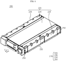
- FIG. 1 is a perspective view schematically showing a battery module according to an embodiment of the present disclosure.
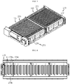
- FIG. 2 is an exploded perspective view schematically showing components of the battery module according to an embodiment of the present disclosure.
- FIG. 3 is a perspective view schematically showing components of the battery module according to an embodiment of the present disclosure.
- the battery module 200 is depicted in a state where an upper cover 220 of a module housing 210 is excluded.
- FIG. 3 in order to show the inside of a battery module 200, the battery module 200 is depicted in a state where an upper cover 220 of a module housing 210 is excluded.
- FIG. 3 in order to show the inside of a battery module 200, the battery module 200 is depicted in a state where an upper cover 220 of a module housing 210 is excluded.
- a positive direction of an X-axis arrow refers to a right direction
- a negative direction thereof refers to a left direction
- a positive direction of a Y-axis arrow refers to a rear direction
- a negative direction thereof refers to a front direction
- a positive direction of a Z-axis direction refers to an upper direction
- a negative direction thereof refers to a lower direction.
- the battery module 200 may include a cell assembly 100, a module housing 210, and a flame-retardant sheet 230.
- the cell assembly 100 may include a plurality of secondary batteries 110 stacked on each other in a front and rear direction.
- the secondary battery 110 may be a pouch-type secondary battery 110.
- each of the two cell assemblies 100 may be configured so that 21 pouch-type secondary batteries 110 are stacked side by side in a front and rear direction (Y direction).
- the pouch-type secondary battery 110 may include an electrode assembly (not shown), an electrolyte (not shown), and a pouch 116.
- the secondary batteries 110 When viewed in the F direction (shown in FIG. 1 ), the secondary batteries 110 may be disposed to be erected approximately perpendicular to the ground (Z direction) so that two wide sides thereof are respectively positioned at front and rear sides and sealing portions are positioned at upper, lower, left and right sides. In other words, each secondary battery 110 may be configured to be erected in a vertical direction. Meanwhile, in this specification, unless otherwise specified, the upper, lower, front, rear, left and right directions will be set based on when viewed in the F direction.
- the pouch 116 may be configured as a pouch having an accommodation portion with a concave shape.
- the electrode assembly and the electrolyte may be accommodated in the accommodation portion.
- each pouch may include an outer insulating layer, a metal layer and an inner adhesive layer, and the inner adhesive layers may be bonded to each other at an edge of the pouch to form a sealing portion.
- a terrace portion may be formed at each end of the secondary battery 110 in a left and right direction (X direction) where a positive electrode lead 111a and a negative electrode lead 111b are formed.
- the electrode assembly is an assembly of an electrode plate coated with an electrode active material and a separator, and may be configured so that at least one positive electrode plate and at least one negative electrode plate are disposed with the separator being interposed therebetween.
- a positive electrode tab may be provided at the positive electrode plate of the electrode assembly, and at least one positive electrode tab may be connected to the positive electrode lead 111a.
- the positive electrode lead 111a may have one end connected to the positive electrode tab and the other end exposed out of the pouch 116, and the exposed portion may serve as an electrode lead of the secondary battery 110, for example a positive electrode terminal of the secondary battery 110.
- a negative electrode tab is provided at the negative electrode plate of the electrode assembly, and at least one negative electrode tab may be connected to the negative electrode lead 111b.
- the negative electrode lead 111b may have one end connected to the negative electrode tab and the other end exposed out of the pouch, and the exposed portion may serve as an electrode lead of the secondary battery 110, for example a negative electrode terminal of the secondary battery 110.
- the positive electrode lead 111a and the negative electrode lead 111b may be formed at the left and right ends in opposite directions (X direction) with respect to the center of the secondary battery 110. That is, the positive electrode lead 111a may be provided at one end (left end) based on the center of the secondary battery 110. In addition, the negative electrode lead 111b may be provided at the other end (right end) based on the center of the secondary battery 110.
- each secondary battery 110 of the cell assembly 100 may be configured such that the positive electrode lead 111a and the negative electrode lead 111b protrude in the left and right direction.
- directions such as 'front', after, left, right, up, and down may vary depending on the position of the observer or the shape of the object. However, in the present specification, for convenience of description, directions such as front, rear, left, right, up, and down are shown separately based on when viewed in the F direction.
- directions such as 'front', 'rear', 'left', 'right', 'upper' and 'lower' used in this specification may vary depending on the position of an observer or the form of a placed object. However, in this specification, for convenience of explanation, the directions such as 'front', 'rear', 'left', 'right', 'upper' and 'lower' are distinguishably expressed based on the case of being viewed in the F direction.
- the positive electrode lead 111a and the negative electrode lead 111b may be configured in a plate shape.
- the positive electrode lead 111a and the negative electrode lead 111b may protrude in a horizontal direction (X direction) in a state where wide sides thereof are erected toward the front and rear direction.
- the horizontal direction may refer to a direction parallel to the ground when the secondary battery 110 is placed on the ground, and may also refer to at least one direction on a plane perpendicular to the vertical direction.
- the battery module 200 according to the present disclosure is not limited to the pouch-type secondary battery 110 described above, and various kinds of secondary batteries 110 known at the time of filing of this application may be employed.
- the at least two or more cell assemblies 100 may be arranged in the front and rear direction.
- two cell assemblies 100 may be arranged in the front and rear direction, and the two cell assemblies 100 may be spaced apart from each other by a predetermined distance.
- the module housing 210 may have an inner space to accommodate the cell assembly 100 therein.
- the module housing 210 may include an upper cover 220, a base plate 255, a front cover 250, and a rear cover 260.
- the base plate 255 may have an area larger than the size of a bottom surface of the at least two cell assemblies 100 so as to mount the at least two cell assemblies 100 to an upper portion thereof.
- the base plate 255 may have a plate shape extending in a horizontal direction.
- the upper cover 220 may include a top portion 224 and a side portion 226.
- the top portion 224 may have a plate shape extending in a horizontal direction to cover an upper portion of the cell assembly 100.
- the side portion 226 may have a plate shape extending downward from both left and right ends of the top portion 224 to cover both left and right sides of the cell assembly 100.
- the side portion 226 may be coupled to a portion of the base plate 255.
- the upper cover 220 may include a top portion 224 having a plate shape extending in the front, rear, left and right directions.
- the upper cover 220 may include two side portions 226 extending downward from both left and right ends of the top portion 224, respectively.
- lower ends of the two side portions 226 may be configured to be coupled with both left and right ends of the base plate 255, respectively.
- the coupling method may be a male and female coupling method or a welding method.
- the side portion 226 may have a beading portion B1 protruding inward toward the secondary battery 110.
- a beading portion B1 protruding inward may be formed on one side portion 226.
- the front cover 250 may be configured to cover the front side of the plurality of secondary batteries 110.
- the front cover 250 may have a plate shape larger than the size of the front surface of the plurality of secondary batteries 110.
- the plate shape may be erected in a vertical direction.
- a portion of the outer circumference of the front cover 250 may be coupled with the base plate 255.
- a lower portion of the outer circumference of the front cover 250 may be coupled to a front end of the base plate 255.
- an upper portion of the outer circumference of the front cover 250 may be coupled to a front end of the upper cover 220.
- the coupling method may employ bolting.
- the rear cover 260 may be configured to cover the rear side of the cell assembly 100.
- the rear cover 260 may have a plate shape larger than the size of the rear surface of the plurality of secondary batteries 110.
- a portion of the outer circumference of the rear cover 260 may be coupled with the base plate 255.
- a lower portion of the outer circumference of the rear cover 260 may be coupled to the front end of the base plate 255.
- an upper portion of the outer circumference of the rear cover 260 may be coupled to the rear end of the upper cover 220.
- the coupling method may employ bolting.
- the rear cover 260 may have a discharge hole 264h formed to allow an external air to flow to the inside or to allow an internal air to flow to the outside.
- the module housing 210 has a structure capable of stably protecting the plurality of secondary batteries 110 from external shocks, it is possible to increase the safety of the battery module 200 against external shocks.
- the battery module 200 of the present disclosure may further include a module BMS 290 configured to control charging and discharging of the cell assembly 100.
- the module BMS 290 may include various sensors and electric circuits to sense the temperature and current of the battery module 200. The sensors and circuits are not shown in the figures.
- the battery module 200 of the present disclosure may include a flame-retardant sheet 280.
- the flame-retardant sheet may be located between the two cell assemblies 100.
- the flame-retardant sheet 280 may have openings 286 formed at both left and right sides thereof so that air may pass therethrough.
- the bus bar assembly 270 may include at least one bus bar 272 and at least one bus bar frame 276 to which the bus bar 272 is mounted.
- the bus bar 272 may be an alloy containing a metal such as copper, nickel or aluminum with excellent electrical conductivity.
- the bus bar 272 may be configured to electrically connect the plurality of secondary batteries 110 to each other. That is, the bus bar 272 may be configured to contact a portion of the electrode lead 111.
- the bus bar 272 may have a plate shape.
- the bus bar 272 may have a plate shape extending in front and rear directions and in upper and lower directions.
- the bus bar frame 276 may include an electrically insulating material.
- the bus bar frame 276 may have a plastic material. More specifically, the plastic material may be polycarbonate, polyvinyl chloride, or the like.
- the battery module 200 may include four bus bar assemblies 270.
- the bus bar assemblies 270 may be located on the left and right sides of the cell assembly 100, respectively.
- Each of the four bus bar assemblies 270 may include four bus bars 272 and a bus bar frame 276 configured so that the four bus bars 272 are mounted to an outer surface thereof.
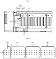
- FIG. 4 is a side view schematically showing a bus bar frame, employed at the battery module according to an embodiment of the present disclosure.
- FIG. 5 is a partial side view schematically showing an inner side surface of the battery module of FIG. 3 .
- the bus bar frame 276 may include a body portion 276a and at least two fixing portions 276b.
- the body portion 276a may have a plate shape so that the at least one bus bar 272 is mounted to an outer surface thereof.
- the body portion 276a may be erected in a vertical direction.
- the body portion 276a may be elongated in a direction along which the plurality of secondary batteries 110 are stacked (the front and rear direction).
- the fixing portion 276b may have a shape protrusively extending outward from the body portion 276a.
- the fixing portions 276b may have a shape protrusively extending outward from an upper portion and a lower portion of the outer surface of the body portion 276a.
- the fixing portion 276b may be configured to be coupled to the flame-retardant sheet 230.
- the flame-retardant sheet 230 may be configured to be interposed between two fixing portions 276b.
- the flame-retardant sheet 230 may be inserted between the fixing portion 276b formed at the upper portion of the body portion 276a and the fixing portion 276b formed at the lower portion and assembled thereto by fitting.
- the bus bar frame 276 of the battery module 200 of the present disclosure may have a plurality of perforated holes H1 through which the electrode leads 111 of the plurality of secondary batteries 110 passes.
- the bus bar frame 276 may have the perforated holes H1 respectively formed at positions corresponding to the electrode leads 111 of the plurality of secondary batteries 110.
- each electrode lead 111 of the plurality of secondary batteries 110 of the cell assembly 100 may be configured to protrude outward through the perforated hole H1 of the bus bar frame 276.
- the perforated hole H1 may have a shape similar to the electrode lead 111.
- the perforated hole H1 may have a rectangular hole elongated in the vertical direction.
- the bus bar 272 may have an insert hole H2 configured to communicate with the perforated hole HI.
- the insert hole H2 may be configured such that the electrode lead 111 of the secondary battery 110 is inserted therein.
- five insert holes H2 may be formed in any one bus bar 272.
- the electrode lead 111 of the secondary battery 110 may be inserted into each of the five insert holes H2, and the inserted portion may be bent in the front and rear direction to contact (be welded to) the outer surface of the bus bar 272.
- the flame-retardant sheet 230 may have a flame-retardant material that does not burn easily.
- the flame-retardant material may be mica, vinyl chloride resin containing chlorine, paraffin chloride, decabromodiphenyl oxide, antimony trioxide, or the like.
- the flame-retardant sheet 230 may have a plate shape. That is, the flame-retardant sheet 230 may have a sheet shape extending in the front and rear direction and in the upper and lower direction. Moreover, the flame-retardant sheet 230 may be configured to close the perforated hole HI. The flame-retardant sheet 230 may be positioned in close contact with the outer side of the bus bar 272. That is, the flame-retardant sheet 230 may be fixed at a position facing the perforated hole H1 of the bus bar frame 276.
- the flame-retardant sheet 230 having a plate shape is located in close contact with the outer side of the bus bar 272 mounted to the bus bar frame 276 to close the perforated hole H1 formed in the bus bar frame 276, if a fire occurs at the cell assembly 100, it is possible to prevent oxygen from being supplied through the perforated hole H1 of the bus bar assembly 270.
- the flame-retardant sheet 230 may prevent the flame generated by thermal runaway or fire of the cell assembly 100 from exploding to other adjacent internal components.
- FIG. 6 is a right side view schematically showing flame-retardant sheets, employed at the battery module according to an embodiment of the present disclosure.
- the flame-retardant sheet 230 may have a plurality of welding holes G1 formed there.
- the welding hole G1 may be formed by perforating a portion of the flame-retardant sheet 230 so that a portion of the electrode lead 111 in contact with the bus bar 272 may be exposed to the outside.
- the plurality of welding holes G1 may be formed at positions corresponding to the welding portions of the electrode leads 111 and the bus bar 272.
- the plurality of welding holes G1 may be formed in each of the four flame-retardant sheets 230 so that a portion of the electrode leads 111 in contact with the bus bar 272 is exposed to the outside.
- the flame-retardant sheet 230 have a plurality of welding holes G1 perforated so that a portion of the electrode lead 111 in contact with the bus bar 272 is exposed to the outside, even if the flame-retardant sheet 230 is positioned on the bus bar 272 of the bus bar assembly 270, the contact portion of the bus bar 272 and the electrode lead 111 may be welded through the plurality of welding holes G1. Accordingly, it is possible to prevent the manufacturing efficiency from deteriorating due to the flame-retardant sheet 230.
- FIG. 7 is a perspective view schematically showing a flame-retardant sheet, employed at a battery module according to another embodiment of the present disclosure.
- a flame-retardant sheet 230A of a battery module may further include a ridged portion 233 on the inner surface 230a as compared to the flame-retardant sheet 230 of FIG. 6 .
- the ridged portion 233 may be formed on the inner surface of the flame-retardant sheet 230A.
- the ridged portion 233 may have a shape protruding inward.
- the ridged portion 233 may be configured to be in close contact with the outer surface of the bus bar 272.
- the ridged portion 233 may have a shape surrounding the outer circumference of the welding hole G1.
- 18 welding holes G1 may be formed in the flame-retardant sheet 230A.
- the ridged portion 233 may be formed at each of the 18 welding holes G1.
- the ridged portion 233 may protrude inward and be in close contact with the outer surface of the bus bar 272 in order to prevent a gap from being created between the flame-retardant sheet 230A and the bus bar 272.
- the flame-retardant sheet 230A since the flame-retardant sheet 230A includes the ridged portion 233 formed on the inner surface thereof facing the bus bar 272, having a shape ridged inward and shaped to surround the outer circumference of the welding hole G1, it is possible to prevent air from entering from the outside to the inside through the welding hole G1 of the flame-retardant sheet 230A.
- FIG. 8 is a perspective view schematically showing a flame-retardant sheet, employed at a battery module according to another embodiment of the present disclosure.
- a flame-retardant sheet 230B of a battery module may further include a protrusion 235 on the inner surface 230A as compared to the flame-retardant sheet 230 of FIG. 6 .
- the protrusion 235 may have a shape protruding inward to a predetermined length so that a portion of the protrusion 235 is inserted into the insert hole H2 of the bus bar 272.
- the flame-retardant sheet 230B may have with five protrusions 235.
- the protrusion 235 may be formed at a position corresponding to the perforated hole H1 ( FIG. 4 ) of the bus bar frame 276.
- the protrusion 235 may be configured to be inserted into the insert hole H2 ( FIG. 5 ) of the bus bar 272.
- the flame-retardant sheet 230B since the flame-retardant sheet 230B includes the protrusion 235 protruding inward so that a portion thereof is inserted into the insert hole H2 of the bus bar 272, it is possible to prevent air from being introduced from the outside to the inside through insert hole H2 communicating with the perforated hole HI. Accordingly, the battery module of the present disclosure may block air inflow to the inside even if a fire or thermal runaway occurs at the cell assembly 100 ( FIG. 2 ), thereby preventing fire or thermal runaway from spreading to other neighboring cell assemblies 100 ( FIG. 2 ).
- FIG. 9 is a partial side view schematically showing a side surface of a battery module according to still another embodiment of the present disclosure.
- a bus bar frame 276C of a battery module 200C may have a fixing hole 276h formed in the fixing portion 276b.
- the fixing hole 276h may be configured such that a portion 272a of the outer circumference of the flame-retardant sheet 230C is inserted therein.
- the fixing portion 276b protruding outward from the body portion 276a may be provided in the bus bar frame 276C.
- the fixing hole 276h may be formed to be perforated in the vertical direction.
- An upper portion 272a of the outer circumference of the flame-retardant sheet 230C may have a shape protruding upward so as to be inserted into the fixing hole 276h.
- Upper and lower portions 272a of the outer circumference of the flame-retardant sheet 230C may have a shape protruding downward so as to be inserted into the fixing hole 276h formed in the fixing portion 276b located below.
- the fixing portion 276b has the fixing hole 276h configured so that the outer circumference of the flame-retardant sheet 230C is inserted therein, the flame-retardant sheet 230C may be easily fixed to the bus bar frame 276C. Moreover, after the flame-retardant sheet 230C is inserted into the bus bar frame 276C, it is possible to prevent the flame-retardant sheet 230C from detaching from the bus bar frame 276C even if an external impact is applied thereto. Accordingly, it is possible to increase the durability of the battery module 200C.
- FIG. 10 is a partial side view schematically showing a side surface of a battery module according to still another embodiment of the present disclosure.
- a bus bar frame 276D of a battery module 200D may further include at least one fixing protrusion 276p formed on the fixing portion 276b.
- the fixing protrusion 276p may be configured to press the outer circumference of the flame-retardant sheet 230 inward to be fixed. That is, the fixing protrusion 276p may have a shape extending from the fixing portion 276b to contact the outer surface of the flame-retardant sheet 230 so as to press the outer surface of the flame-retardant sheet 230 inward.
- the fixing protrusion 276p may be formed on each of the two fixing portions 276b of the bus bar frame 276.
- the fixing protrusion 276p protruding downward may be formed on the fixing portion 276b located at an upper part of the bus bar frame 276.
- the fixing protrusion 276p protruding upward may be formed on the fixing portion 276b located at a lower part of the bus bar frame 276.
- the fixing protrusion 276p formed on the fixing portion 276b may be configured to press the outer circumference of the flame-retardant sheet 230 inward.
- the fixing portion 276b has at least one fixing protrusion 276p configured to press and fix the outer circumference of the flame-retardant sheet 230 inward, the flame-retardant sheet 230 may be easily fixed to the bus bar frame 276. Moreover, after the flame-retardant sheet 230 is inserted into the bus bar frame 276, it is possible to prevent the flame-retardant sheet 230 from detaching from the bus bar frame 276 even if an external impact is applied thereto. Accordingly, it is possible to increase the durability of the battery module 200D.
- FIG. 11 is a partial side view schematically showing a side surface of a battery module according to still another embodiment of the present disclosure.
- FIG. 12 is a perspective view schematically showing a pressing pin, employed at the battery module of FIG. 11 .
- a battery module 200E may further include a pressing pin 240 as compared to the battery module 200 of FIG. 6 .
- the pressing pin 240 may be configured to press a portion S1 of the flame-retardant sheet 230 facing the insert hole H2 of the bus bar 272.
- one flame-retardant sheet 230 may have five portions S1 of the flame-retardant sheet 230 facing the insert hole H2 of the bus bar 272.
- Each of the five pressing pins 240 may press a portion of the flame-retardant sheet 230 facing the insert hole H2 of the bus bar 272 inward.
- the pressing pin 240 may include a pressing portion 245 and a connecting portion 241.
- the connecting portion 241 may be configured to be fitted into an end of the fixing portion 276b formed at the bus bar frame 276.
- the connecting portion 241 may have a clip shape.
- the pressing portion 245 may be a portion extending from the connecting portion 241 to a portion of the flame-retardant sheet 230 facing the insert hole H2 of the bus bar 272.
- the pressing portion 245 may elastically press the outer surface of the flame-retardant sheet 230 inward.
- the pressing portion 245 may have a structure K1 bent in at least one direction.
- the present disclosure further includes the pressing pin 240 configured to press a portion of the flame-retardant sheet 230 facing the insert hole H2 of the bus bar 272 inward, at ordinary time, the pressing pin 240 may bring the flame-retardant sheet 230 into close contact with the bus bar 272 so that the perforated hole H1 of the bus bar frame 276 is closed. Meanwhile, when a fire or thermal runaway occurs at the cell assembly 100, the pressing pin 240 may flexibly allow a high-pressure gas ejected by internal pressure to be discharged through the perforated hole H1 and the insert hole H2 of the bus bar frame 276 while pushing the flame-retardant sheet 230 outward. Accordingly, it is possible to prevent an external air from being introduced into the cell assembly 100 while discharging the high-temperature gas of the cell assembly 100, thereby preventing the fire or thermal runaway of the battery module 200E from spreading to other neighboring cell assemblies 100.
- FIG. 13 is a perspective view schematically showing an energy storage system according to an embodiment of the present disclosure.
- a battery rack 300 may further include a rack BMS (Battery Management System) 330 provided inside or outside a rack case 310 to exchange information with the plurality of module BMS 290.
- a rack BMS Battery Management System
- An energy storage system may include at least one battery rack 300 according to the present disclosure.
- the energy storage system may include a plurality of battery racks 300 according to the present disclosure.
- the plurality of battery racks 300 may be electrically connected to each other.
- the energy storage system according to the present disclosure may be implemented in various forms such as a smart grid system or an electric charging station.
- battery module 100 cell assembly 110: secondary battery 210: module housing 270: bus bar assembly 272, 276: bus bar, bus bar frame HI: perforated hole H2: insert hole 276a: body portion 276b: fixing portion 276h: fixing hole 276p: fixing protrusion 230: flame-retardant sheet G1: welding hole 233: ridged portion 235: protrusion 240: pressing pin 300: battery rack 310: rack case
Landscapes
- Chemical & Material Sciences (AREA)
- Chemical Kinetics & Catalysis (AREA)
- Electrochemistry (AREA)
- General Chemical & Material Sciences (AREA)
- Engineering & Computer Science (AREA)
- Manufacturing & Machinery (AREA)
- Connection Of Batteries Or Terminals (AREA)
- Battery Mounting, Suspending (AREA)
Applications Claiming Priority (2)
| Application Number | Priority Date | Filing Date | Title |
|---|---|---|---|
| KR1020200005522A KR20210092039A (ko) | 2020-01-15 | 2020-01-15 | 방염 시트를 구비한 배터리 모듈, 이를 포함하는 배터리 랙, 및 전력 저장 시스템 |
| PCT/KR2021/000560 WO2021145706A1 (ko) | 2020-01-15 | 2021-01-14 | 방염 시트를 구비한 배터리 모듈, 이를 포함하는 배터리 랙, 및 전력 저장 시스템 |
Publications (2)
| Publication Number | Publication Date |
|---|---|
| EP3989355A1 true EP3989355A1 (de) | 2022-04-27 |
| EP3989355A4 EP3989355A4 (de) | 2022-10-05 |
Family
ID=76864357
Family Applications (1)
| Application Number | Title | Priority Date | Filing Date |
|---|---|---|---|
| EP21740679.2A Pending EP3989355A4 (de) | 2020-01-15 | 2021-01-14 | Batteriemodul mit einer flammhemmenden folie, batteriegestell damit und energiespeichersystem |
Country Status (6)
| Country | Link |
|---|---|
| US (1) | US20220367971A1 (de) |
| EP (1) | EP3989355A4 (de) |
| JP (1) | JP7431867B2 (de) |
| KR (1) | KR20210092039A (de) |
| CN (1) | CN114207921A (de) |
| WO (1) | WO2021145706A1 (de) |
Families Citing this family (10)
| Publication number | Priority date | Publication date | Assignee | Title |
|---|---|---|---|---|
| KR102611509B1 (ko) * | 2021-08-19 | 2023-12-07 | 주식회사 한일하이테크 | 보호 구조가 구비된 배터리 운반 트레이 |
| KR20230032076A (ko) * | 2021-08-30 | 2023-03-07 | 에스케이온 주식회사 | 배터리 모듈 |
| KR20230077873A (ko) * | 2021-11-26 | 2023-06-02 | 주식회사 엘지에너지솔루션 | 전지 모듈 |
| KR20230126842A (ko) * | 2022-02-24 | 2023-08-31 | 에스케이온 주식회사 | 배터리 모듈 |
| CN114552103B (zh) * | 2022-04-26 | 2022-06-24 | 南通龙海电子科技有限公司 | 一种钛酸锂电池组装结构 |
| KR20230168499A (ko) * | 2022-06-07 | 2023-12-14 | 에스케이온 주식회사 | 배터리 모듈 |
| KR20240007856A (ko) * | 2022-07-08 | 2024-01-17 | 주식회사 엘지에너지솔루션 | 벤팅 구조가 개선된 전지 모듈 |
| KR102622154B1 (ko) * | 2023-03-17 | 2024-01-08 | 주식회사 가드케이 | 질식 소화기능을 갖는 화재 방지시스템 |
| KR102583756B1 (ko) * | 2023-03-17 | 2023-09-27 | 주식회사 가드케이 | 화재 확산 방지기능을 갖는 데이터센터 서버 |
| CN116505204A (zh) * | 2023-06-28 | 2023-07-28 | 深圳市驭能科技有限公司 | 一种高阻燃可靠性采集集成母排及其制备方法 |
Family Cites Families (13)
| Publication number | Priority date | Publication date | Assignee | Title |
|---|---|---|---|---|
| US20080280198A1 (en) * | 2007-05-07 | 2008-11-13 | Ajith Kuttannair Kumar | Battery mechanical packaging |
| JP2012113896A (ja) * | 2010-11-23 | 2012-06-14 | Denso Corp | 組電池 |
| KR101944826B1 (ko) * | 2011-10-18 | 2019-04-17 | 에스케이이노베이션 주식회사 | 배터리 모듈 및 이를 포함하는 중·대형 배터리 모듈 |
| EP2894695A3 (de) * | 2013-11-05 | 2015-12-02 | Tyco Electronics Amp Korea Ltd. | Batteriezellenverbindungsplatine |
| CN113300029A (zh) | 2015-06-18 | 2021-08-24 | 24M技术公司 | 单袋电池单元以及制造方法 |
| KR102022590B1 (ko) * | 2015-09-21 | 2019-09-18 | 주식회사 엘지화학 | 배터리 모듈 |
| CN108604653B (zh) | 2016-01-26 | 2021-11-12 | 三洋电机株式会社 | 电池组 |
| KR102082903B1 (ko) * | 2016-02-22 | 2020-02-28 | 주식회사 엘지화학 | 배터리 모듈, 이러한 배터리 모듈을 포함하는 배터리 팩 및 이러한 배터리 팩을 포함하는 자동차 |
| KR102034208B1 (ko) | 2016-03-03 | 2019-10-18 | 주식회사 엘지화학 | 배터리 모듈, 이러한 배터리 모듈을 포함하는 배터리 팩 및 이러한 배터리 팩을 포함하는 자동차 |
| US20180138478A1 (en) * | 2016-11-14 | 2018-05-17 | Anhui Xinen Technology Co., Ltd. | Alleviating explosion propagation in a battery module |
| KR102588723B1 (ko) | 2017-05-08 | 2023-10-12 | 세키스이가가쿠 고교가부시키가이샤 | 액정 표시 소자용 시일제, 상하 도통 재료, 및, 액정 표시 소자 |
| EP3460870B1 (de) * | 2017-09-25 | 2023-12-20 | Ursatech Ltd. | Batteriegehäuse zur verzögerung von thermischem durchgehen |
| EP3948969A4 (de) | 2019-04-01 | 2023-03-22 | Spear Power Systems, Inc. | Vorrichtung zur verminderung der thermischen ereignisausbreitung für batteriesysteme |
-
2020
- 2020-01-15 KR KR1020200005522A patent/KR20210092039A/ko unknown
-
2021
- 2021-01-14 CN CN202180004729.4A patent/CN114207921A/zh active Pending
- 2021-01-14 JP JP2021577109A patent/JP7431867B2/ja active Active
- 2021-01-14 WO PCT/KR2021/000560 patent/WO2021145706A1/ko unknown
- 2021-01-14 US US17/771,853 patent/US20220367971A1/en active Pending
- 2021-01-14 EP EP21740679.2A patent/EP3989355A4/de active Pending
Also Published As
| Publication number | Publication date |
|---|---|
| EP3989355A4 (de) | 2022-10-05 |
| CN114207921A (zh) | 2022-03-18 |
| WO2021145706A1 (ko) | 2021-07-22 |
| US20220367971A1 (en) | 2022-11-17 |
| JP7431867B2 (ja) | 2024-02-15 |
| KR20210092039A (ko) | 2021-07-23 |
| JP2022539114A (ja) | 2022-09-07 |
Similar Documents
| Publication | Publication Date | Title |
|---|---|---|
| EP3989355A1 (de) | Batteriemodul mit einer flammhemmenden folie, batteriegestell damit und energiespeichersystem | |
| US20240079721A1 (en) | Battery module, battery rack comprising same, and power storage device | |
| US11462799B2 (en) | Battery module having gas discharge structure | |
| CN104577017B (zh) | 具有熔断器单元的可再充电电池和电池模块 | |
| EP3902026A1 (de) | Batteriemodul, bestehend aus grundplatte mit gasentladungskanal, batteriepaket und stromspeicher | |
| US10892468B2 (en) | Battery module with short-circuit unit, and battery pack and vehicle including the same | |
| KR20210093636A (ko) | 소화 플레이트를 포함한 배터리 모듈, 이를 포함하는 배터리 랙, 및 전력 저장 시스템 | |
| EP3926735A1 (de) | Batteriepack, elektronische vorrichtung und fahrzeug | |
| EP3940867A1 (de) | Batteriesatz mit verstärkter kurzschlussvermeidung und stossschutzstruktur | |
| CN114303277A (zh) | 电池模块和包括该电池模块的电池组 | |
| US20230201640A1 (en) | Battery module with improved fire protection performance | |
| EP4152503A1 (de) | Batteriepack und fahrzeug damit | |
| EP3770992A1 (de) | Batteriemodul mit innenplatte | |
| EP4138188A1 (de) | Batteriemodul, batteriegestell und energiespeichervorrichtung | |
| EP4250452A1 (de) | Batteriepack und vorrichtung damit | |
| CN116491021A (zh) | 具有提高的安全性的电池组 |
Legal Events
| Date | Code | Title | Description |
|---|---|---|---|
| STAA | Information on the status of an ep patent application or granted ep patent |
Free format text: STATUS: THE INTERNATIONAL PUBLICATION HAS BEEN MADE |
|
| PUAI | Public reference made under article 153(3) epc to a published international application that has entered the european phase |
Free format text: ORIGINAL CODE: 0009012 |
|
| STAA | Information on the status of an ep patent application or granted ep patent |
Free format text: STATUS: REQUEST FOR EXAMINATION WAS MADE |
|
| 17P | Request for examination filed |
Effective date: 20220121 |
|
| AK | Designated contracting states |
Kind code of ref document: A1 Designated state(s): AL AT BE BG CH CY CZ DE DK EE ES FI FR GB GR HR HU IE IS IT LI LT LU LV MC MK MT NL NO PL PT RO RS SE SI SK SM TR |
|
| A4 | Supplementary search report drawn up and despatched |
Effective date: 20220905 |
|
| RIC1 | Information provided on ipc code assigned before grant |
Ipc: H01M 50/507 20210101ALI20220830BHEP Ipc: H01M 50/211 20210101ALI20220830BHEP Ipc: H01M 10/658 20140101ALI20220830BHEP Ipc: H01M 10/647 20140101ALI20220830BHEP Ipc: H01M 10/613 20140101ALI20220830BHEP Ipc: H01M 50/20 20210101ALI20220830BHEP Ipc: H01M 50/24 20210101ALI20220830BHEP Ipc: H01M 50/502 20210101ALI20220830BHEP Ipc: H01M 50/572 20210101AFI20220830BHEP |
|
| DAV | Request for validation of the european patent (deleted) | ||
| DAX | Request for extension of the european patent (deleted) |