EP3989336A1 - Battery module having structure into which cooling water can be introduced when thermal runaway phenomenon occurs, and battery pack and energy storage device comprising same - Google Patents
Battery module having structure into which cooling water can be introduced when thermal runaway phenomenon occurs, and battery pack and energy storage device comprising same Download PDFInfo
- Publication number
- EP3989336A1 EP3989336A1 EP20837142.7A EP20837142A EP3989336A1 EP 3989336 A1 EP3989336 A1 EP 3989336A1 EP 20837142 A EP20837142 A EP 20837142A EP 3989336 A1 EP3989336 A1 EP 3989336A1
- Authority
- EP
- European Patent Office
- Prior art keywords
- battery
- module
- battery module
- cooling water
- housing
- Prior art date
- Legal status (The legal status is an assumption and is not a legal conclusion. Google has not performed a legal analysis and makes no representation as to the accuracy of the status listed.)
- Pending
Links
Images





Classifications
-
- H—ELECTRICITY
- H01—ELECTRIC ELEMENTS
- H01M—PROCESSES OR MEANS, e.g. BATTERIES, FOR THE DIRECT CONVERSION OF CHEMICAL ENERGY INTO ELECTRICAL ENERGY
- H01M10/00—Secondary cells; Manufacture thereof
- H01M10/60—Heating or cooling; Temperature control
- H01M10/65—Means for temperature control structurally associated with the cells
- H01M10/656—Means for temperature control structurally associated with the cells characterised by the type of heat-exchange fluid
- H01M10/6561—Gases
-
- H—ELECTRICITY
- H01—ELECTRIC ELEMENTS
- H01M—PROCESSES OR MEANS, e.g. BATTERIES, FOR THE DIRECT CONVERSION OF CHEMICAL ENERGY INTO ELECTRICAL ENERGY
- H01M10/00—Secondary cells; Manufacture thereof
- H01M10/60—Heating or cooling; Temperature control
- H01M10/65—Means for temperature control structurally associated with the cells
- H01M10/656—Means for temperature control structurally associated with the cells characterised by the type of heat-exchange fluid
- H01M10/6567—Liquids
-
- A—HUMAN NECESSITIES
- A62—LIFE-SAVING; FIRE-FIGHTING
- A62C—FIRE-FIGHTING
- A62C2/00—Fire prevention or containment
- A62C2/06—Physical fire-barriers
-
- A—HUMAN NECESSITIES
- A62—LIFE-SAVING; FIRE-FIGHTING
- A62C—FIRE-FIGHTING
- A62C2/00—Fire prevention or containment
- A62C2/06—Physical fire-barriers
- A62C2/065—Physical fire-barriers having as the main closure device materials, whose characteristics undergo an irreversible change under high temperatures, e.g. intumescent
-
- A—HUMAN NECESSITIES
- A62—LIFE-SAVING; FIRE-FIGHTING
- A62C—FIRE-FIGHTING
- A62C3/00—Fire prevention, containment or extinguishing specially adapted for particular objects or places
- A62C3/14—Fire prevention, containment or extinguishing specially adapted for particular objects or places in connection with doors, windows, ventilators, partitions, or shutters, e.g. automatic closing
-
- A—HUMAN NECESSITIES
- A62—LIFE-SAVING; FIRE-FIGHTING
- A62C—FIRE-FIGHTING
- A62C3/00—Fire prevention, containment or extinguishing specially adapted for particular objects or places
- A62C3/16—Fire prevention, containment or extinguishing specially adapted for particular objects or places in electrical installations, e.g. cableways
-
- H—ELECTRICITY
- H01—ELECTRIC ELEMENTS
- H01M—PROCESSES OR MEANS, e.g. BATTERIES, FOR THE DIRECT CONVERSION OF CHEMICAL ENERGY INTO ELECTRICAL ENERGY
- H01M10/00—Secondary cells; Manufacture thereof
- H01M10/42—Methods or arrangements for servicing or maintenance of secondary cells or secondary half-cells
- H01M10/425—Structural combination with electronic components, e.g. electronic circuits integrated to the outside of the casing
- H01M10/4257—Smart batteries, e.g. electronic circuits inside the housing of the cells or batteries
-
- H—ELECTRICITY
- H01—ELECTRIC ELEMENTS
- H01M—PROCESSES OR MEANS, e.g. BATTERIES, FOR THE DIRECT CONVERSION OF CHEMICAL ENERGY INTO ELECTRICAL ENERGY
- H01M10/00—Secondary cells; Manufacture thereof
- H01M10/42—Methods or arrangements for servicing or maintenance of secondary cells or secondary half-cells
- H01M10/48—Accumulators combined with arrangements for measuring, testing or indicating the condition of cells, e.g. the level or density of the electrolyte
- H01M10/482—Accumulators combined with arrangements for measuring, testing or indicating the condition of cells, e.g. the level or density of the electrolyte for several batteries or cells simultaneously or sequentially
-
- H—ELECTRICITY
- H01—ELECTRIC ELEMENTS
- H01M—PROCESSES OR MEANS, e.g. BATTERIES, FOR THE DIRECT CONVERSION OF CHEMICAL ENERGY INTO ELECTRICAL ENERGY
- H01M10/00—Secondary cells; Manufacture thereof
- H01M10/42—Methods or arrangements for servicing or maintenance of secondary cells or secondary half-cells
- H01M10/48—Accumulators combined with arrangements for measuring, testing or indicating the condition of cells, e.g. the level or density of the electrolyte
- H01M10/486—Accumulators combined with arrangements for measuring, testing or indicating the condition of cells, e.g. the level or density of the electrolyte for measuring temperature
-
- H—ELECTRICITY
- H01—ELECTRIC ELEMENTS
- H01M—PROCESSES OR MEANS, e.g. BATTERIES, FOR THE DIRECT CONVERSION OF CHEMICAL ENERGY INTO ELECTRICAL ENERGY
- H01M10/00—Secondary cells; Manufacture thereof
- H01M10/60—Heating or cooling; Temperature control
- H01M10/61—Types of temperature control
- H01M10/613—Cooling or keeping cold
-
- H—ELECTRICITY
- H01—ELECTRIC ELEMENTS
- H01M—PROCESSES OR MEANS, e.g. BATTERIES, FOR THE DIRECT CONVERSION OF CHEMICAL ENERGY INTO ELECTRICAL ENERGY
- H01M10/00—Secondary cells; Manufacture thereof
- H01M10/60—Heating or cooling; Temperature control
- H01M10/62—Heating or cooling; Temperature control specially adapted for specific applications
- H01M10/627—Stationary installations, e.g. power plant buffering or backup power supplies
-
- H—ELECTRICITY
- H01—ELECTRIC ELEMENTS
- H01M—PROCESSES OR MEANS, e.g. BATTERIES, FOR THE DIRECT CONVERSION OF CHEMICAL ENERGY INTO ELECTRICAL ENERGY
- H01M10/00—Secondary cells; Manufacture thereof
- H01M10/60—Heating or cooling; Temperature control
- H01M10/63—Control systems
-
- H—ELECTRICITY
- H01—ELECTRIC ELEMENTS
- H01M—PROCESSES OR MEANS, e.g. BATTERIES, FOR THE DIRECT CONVERSION OF CHEMICAL ENERGY INTO ELECTRICAL ENERGY
- H01M10/00—Secondary cells; Manufacture thereof
- H01M10/60—Heating or cooling; Temperature control
- H01M10/65—Means for temperature control structurally associated with the cells
- H01M10/656—Means for temperature control structurally associated with the cells characterised by the type of heat-exchange fluid
- H01M10/6561—Gases
- H01M10/6562—Gases with free flow by convection only
-
- H—ELECTRICITY
- H01—ELECTRIC ELEMENTS
- H01M—PROCESSES OR MEANS, e.g. BATTERIES, FOR THE DIRECT CONVERSION OF CHEMICAL ENERGY INTO ELECTRICAL ENERGY
- H01M10/00—Secondary cells; Manufacture thereof
- H01M10/60—Heating or cooling; Temperature control
- H01M10/65—Means for temperature control structurally associated with the cells
- H01M10/656—Means for temperature control structurally associated with the cells characterised by the type of heat-exchange fluid
- H01M10/6567—Liquids
- H01M10/6568—Liquids characterised by flow circuits, e.g. loops, located externally to the cells or cell casings
-
- H—ELECTRICITY
- H01—ELECTRIC ELEMENTS
- H01M—PROCESSES OR MEANS, e.g. BATTERIES, FOR THE DIRECT CONVERSION OF CHEMICAL ENERGY INTO ELECTRICAL ENERGY
- H01M50/00—Constructional details or processes of manufacture of the non-active parts of electrochemical cells other than fuel cells, e.g. hybrid cells
- H01M50/20—Mountings; Secondary casings or frames; Racks, modules or packs; Suspension devices; Shock absorbers; Transport or carrying devices; Holders
- H01M50/204—Racks, modules or packs for multiple batteries or multiple cells
-
- H—ELECTRICITY
- H01—ELECTRIC ELEMENTS
- H01M—PROCESSES OR MEANS, e.g. BATTERIES, FOR THE DIRECT CONVERSION OF CHEMICAL ENERGY INTO ELECTRICAL ENERGY
- H01M50/00—Constructional details or processes of manufacture of the non-active parts of electrochemical cells other than fuel cells, e.g. hybrid cells
- H01M50/20—Mountings; Secondary casings or frames; Racks, modules or packs; Suspension devices; Shock absorbers; Transport or carrying devices; Holders
- H01M50/233—Mountings; Secondary casings or frames; Racks, modules or packs; Suspension devices; Shock absorbers; Transport or carrying devices; Holders characterised by physical properties of casings or racks, e.g. dimensions
- H01M50/24—Mountings; Secondary casings or frames; Racks, modules or packs; Suspension devices; Shock absorbers; Transport or carrying devices; Holders characterised by physical properties of casings or racks, e.g. dimensions adapted for protecting batteries from their environment, e.g. from corrosion
-
- H—ELECTRICITY
- H01—ELECTRIC ELEMENTS
- H01M—PROCESSES OR MEANS, e.g. BATTERIES, FOR THE DIRECT CONVERSION OF CHEMICAL ENERGY INTO ELECTRICAL ENERGY
- H01M50/00—Constructional details or processes of manufacture of the non-active parts of electrochemical cells other than fuel cells, e.g. hybrid cells
- H01M50/20—Mountings; Secondary casings or frames; Racks, modules or packs; Suspension devices; Shock absorbers; Transport or carrying devices; Holders
- H01M50/251—Mountings; Secondary casings or frames; Racks, modules or packs; Suspension devices; Shock absorbers; Transport or carrying devices; Holders specially adapted for stationary devices, e.g. power plant buffering or backup power supplies
-
- H—ELECTRICITY
- H01—ELECTRIC ELEMENTS
- H01M—PROCESSES OR MEANS, e.g. BATTERIES, FOR THE DIRECT CONVERSION OF CHEMICAL ENERGY INTO ELECTRICAL ENERGY
- H01M50/00—Constructional details or processes of manufacture of the non-active parts of electrochemical cells other than fuel cells, e.g. hybrid cells
- H01M50/20—Mountings; Secondary casings or frames; Racks, modules or packs; Suspension devices; Shock absorbers; Transport or carrying devices; Holders
- H01M50/258—Modular batteries; Casings provided with means for assembling
-
- H—ELECTRICITY
- H01—ELECTRIC ELEMENTS
- H01M—PROCESSES OR MEANS, e.g. BATTERIES, FOR THE DIRECT CONVERSION OF CHEMICAL ENERGY INTO ELECTRICAL ENERGY
- H01M50/00—Constructional details or processes of manufacture of the non-active parts of electrochemical cells other than fuel cells, e.g. hybrid cells
- H01M50/50—Current conducting connections for cells or batteries
- H01M50/502—Interconnectors for connecting terminals of adjacent batteries; Interconnectors for connecting cells outside a battery casing
-
- H—ELECTRICITY
- H01—ELECTRIC ELEMENTS
- H01M—PROCESSES OR MEANS, e.g. BATTERIES, FOR THE DIRECT CONVERSION OF CHEMICAL ENERGY INTO ELECTRICAL ENERGY
- H01M50/00—Constructional details or processes of manufacture of the non-active parts of electrochemical cells other than fuel cells, e.g. hybrid cells
- H01M50/50—Current conducting connections for cells or batteries
- H01M50/502—Interconnectors for connecting terminals of adjacent batteries; Interconnectors for connecting cells outside a battery casing
- H01M50/507—Interconnectors for connecting terminals of adjacent batteries; Interconnectors for connecting cells outside a battery casing comprising an arrangement of two or more busbars within a container structure, e.g. busbar modules
-
- H—ELECTRICITY
- H01—ELECTRIC ELEMENTS
- H01M—PROCESSES OR MEANS, e.g. BATTERIES, FOR THE DIRECT CONVERSION OF CHEMICAL ENERGY INTO ELECTRICAL ENERGY
- H01M10/00—Secondary cells; Manufacture thereof
- H01M10/42—Methods or arrangements for servicing or maintenance of secondary cells or secondary half-cells
- H01M10/425—Structural combination with electronic components, e.g. electronic circuits integrated to the outside of the casing
- H01M2010/4271—Battery management systems including electronic circuits, e.g. control of current or voltage to keep battery in healthy state, cell balancing
-
- H—ELECTRICITY
- H01—ELECTRIC ELEMENTS
- H01M—PROCESSES OR MEANS, e.g. BATTERIES, FOR THE DIRECT CONVERSION OF CHEMICAL ENERGY INTO ELECTRICAL ENERGY
- H01M2200/00—Safety devices for primary or secondary batteries
- H01M2200/10—Temperature sensitive devices
-
- H—ELECTRICITY
- H01—ELECTRIC ELEMENTS
- H01M—PROCESSES OR MEANS, e.g. BATTERIES, FOR THE DIRECT CONVERSION OF CHEMICAL ENERGY INTO ELECTRICAL ENERGY
- H01M2220/00—Batteries for particular applications
- H01M2220/10—Batteries in stationary systems, e.g. emergency power source in plant
-
- Y—GENERAL TAGGING OF NEW TECHNOLOGICAL DEVELOPMENTS; GENERAL TAGGING OF CROSS-SECTIONAL TECHNOLOGIES SPANNING OVER SEVERAL SECTIONS OF THE IPC; TECHNICAL SUBJECTS COVERED BY FORMER USPC CROSS-REFERENCE ART COLLECTIONS [XRACs] AND DIGESTS
- Y02—TECHNOLOGIES OR APPLICATIONS FOR MITIGATION OR ADAPTATION AGAINST CLIMATE CHANGE
- Y02E—REDUCTION OF GREENHOUSE GAS [GHG] EMISSIONS, RELATED TO ENERGY GENERATION, TRANSMISSION OR DISTRIBUTION
- Y02E60/00—Enabling technologies; Technologies with a potential or indirect contribution to GHG emissions mitigation
- Y02E60/10—Energy storage using batteries
Definitions
- the present disclosure relates to a battery module having a structure for cooling water introduction when thermal runaway occurs, and a battery pack and an energy storage system comprising the same, and more particularly, to a battery module in which when thermal runaway is detected from a certain battery module in a battery pack including a plurality of battery modules, cooling water is introduced into the corresponding battery module to prevent the thermal runaway from propagating to adjacent battery modules, and a battery pack and an energy storage system comprising the same.
- thermal runaway occurs in a battery module including a plurality of battery cells.
- a failure such as a short circuit occurs in a certain battery cell and the temperature of the battery cell exceeds the critical temperature.
- thermal runaway occurs, the safety issue may arise.
- the battery module adopts an air-cooled structure
- the present disclosure is designed to solve the above-described problem, and therefore the present disclosure is aimed at preventing flames from spreading by quickly lowering the internal temperature of a battery module when thermal runaway occurs in a certain battery cell within the battery module and results in flames.
- a battery module includes a plurality of battery cells, a module housing in which a cell stack is received, the cell stack being formed by stacking the plurality of battery cells, an air inlet passing through the module housing on one side of a stack direction of the cell stack, an air outlet passing through the module housing on the other side in the stack direction of the cell stack, and an expandable pad disposed inside of the air inlet and the air outlet to close the air inlet and the air outlet by expansion upon contact with cooling water introduced into the module housing.
- the expandable pad may be attached to an inner surface of the module housing.
- a pair of expandable pads may be provided, and the pair of expandable pads may be attached to upper and lower inner surfaces of the module housing respectively.
- At least part of the expandable pad may be inserted into a receiving groove formed in an inner surface of the module housing.
- the battery module may include a mesh plate disposed on each of two sides of the expandable pad to guide movement for expansion of the expandable pad.
- the battery module may include a pair of busbar frames coupled to one side and the other side in a widthwise direction of the cell stack respectively.
- the air inlet and the air outlet may be formed at locations corresponding to an empty space between the busbar frames and the module housing.
- a battery pack includes a pack housing, a plurality of battery modules stacked in the pack housing, a water tank disposed on a module stack including the plurality of battery modules to store cooling water, a cooling water pipe connecting the water tank to the battery modules, at least one sensor installed in the pack housing to detect thermal runaway occurring in a certain battery module among the plurality of battery modules, and a controller to output a control signal to introduce the cooling water into the battery module through the cooling water pipe when the thermal runaway is detected by the sensor.
- the battery pack may include a plurality of valves installed in the cooling water pipe, and each of the plurality of valves may be installed adjacent to the plurality of battery modules to individually allow or block a flow of the cooling water introduced into the plurality of battery modules.
- the sensor may be installed in each of the plurality of battery modules.
- the controller may output a control signal to open the valve installed adjacent to the battery module in which the thermal runaway is detected by the sensor among the plurality of valves.
- An energy storage system includes a plurality of battery packs according to an embodiment of the present disclosure.
- a battery pack including air-cooled battery modules can effectively prevent thermal runaway propagation by applying a structure for blocking air channels for cooling to allow cooling water to stay inside when the cooling water is introduced into a battery module in which thermal runaway occurred,.
- an energy storage system includes a plurality of battery packs 100 according to an embodiment of the present disclosure.
- the battery pack 100 includes a pack housing 110, a battery module 120, a water tank 130, a controller 140, a cooling water pipe 150 and a sensor 160.
- the pack housing 110 is an approximately rectangular frame defining the shape of the battery pack 100, and has a space in which a plurality of battery modules 120, the water tank 130, the controller 140, the cooling water pipe 150 and the sensor 160 are installed.
- the plurality of battery modules 120 is provided, and the plurality of battery modules 120 is stacked on top of each other within the pack housing 110 to form a module stack.
- the detailed structure of the battery module 120 will be described in detail below with reference to FIGS. 4 to 7 .
- the water tank 130 is provided in the pack housing 110 to store cooling water to be supplied to the battery module 120 when thermal runaway occurs in the battery module 120.
- the water tank 130 may be disposed on the module stack for quick and good supply of cooling water. In this case, cooling water may be supplied to the battery module 120 quickly by a free fall and cooling water pressure without using a separate cooling water pump. For quicker and better supply of cooling water, a separate cooling water pump may be applied to the water tank 130.
- the controller 140 may be connected to the sensor 160 and the water tank 130 to output a control signal for opening the water tank 130 in response to a sensing signal from the sensor 160.
- the controller 140 may function as a battery management system (BMS) connected to each of the battery modules 120 to manage the charge/discharge.
- BMS battery management system
- the controller 140 When gas or a temperature rise above a reference value is detected in the battery pack 100 due to thermal runaway occurred in at least one of the plurality of battery modules 120, the controller 140 outputs a control signal for opening the water tank 130 to supply cooling water to the battery module 120.
- the cooling water is supplied in a sequential order from the top battery module 120 to the bottom battery module 120. Accordingly, it is possible to put out the flames in the battery module 120 and cool down the battery module 120, thereby preventing the thermal runaway from propagating to the entire battery pack 100.
- the cooling water pipe 150 connects the water tank 130 to the battery module 120 and acts as a passage to transport the cooling water supplied from the water tank 130 to the battery module 120. To perform this function, one end of the cooling water pipe 150 is connected to the water tank, and the other end is divided into the number of branches corresponding to the number of battery modules 120, each branch connected to each of the plurality of battery modules 120.
- the sensor 160 senses an increase in temperature and/or gas generation, and transmits a sensing signal to the controller 140.
- the sensor 160 may be a temperature sensor or a gas detection sensor, and a combination thereof.
- the sensor 160 is installed in the pack housing 110 to detect an increase in the internal temperature or gas generation in the battery pack 100.
- the sensor 160 may be attached to the inner or outer side of each of the plurality of battery modules 120 to quickly sense the temperature of the battery module 120 and/or gas generated from the battery module 120.
- the battery module 120 applied to the battery pack 100 will be described in more detail below with reference to FIGS. 4 to 7 .
- the battery module 120 includes a plurality of battery cells 121, a busbar frame 122, a module housing 123, an air inlet 124, an air outlet 125 and an expandable pad 126.
- the plurality of battery cells 121 is provided, and the plurality of battery cells 121 is stacked to form a cell stack.
- the battery cell 121 may include, for example, a pouch type battery cell.
- the battery cell 121 has a pair of electrode leads 121a extending on two sides in the lengthwise direction respectively.
- a pair of busbar frames 122 are provided, and the busbar frames 122 cover one side and the other side in the widthwise direction of the cell stack (the direction in which the electrode leads are formed) respectively.
- the electrode leads 121a of the battery cell 121 extend through slits formed in the busbar frames 122, and they are bent and fixed onto the busbar frames 122 by welding. That is, the plurality of battery cells 121 may be electrically connected by the busbar frames 122.
- the module housing 123 has a substantially rectangular parallelepiped shape, and receives the cell stack inside.
- the air inlet 124 and the air outlet 125 are formed on one side and the other side in the lengthwise direction of the module housing 123.
- the air inlet 124 is formed on one side (front side) in the stack direction of the cell stack, i.e., one side in the lengthwise direction of the battery module 120.
- the air inlet 124 is formed in the shape of a hole passing through the module housing 123.
- the air outlet 125 is formed on the other side (rear side) in the stack direction of the cell stack, i.e., the other side in the lengthwise direction of the battery module 120.
- the air outlet 125 is formed in the shape of a hole passing through the module housing 123.
- the air inlet 124 and the air outlet 125 are disposed on the opposite sides diagonally across the battery module 120 along the lengthwise direction (the stack direction of the cell stack).
- an empty space is formed between the busbar frames 122 and the module housing 123. That is, an empty space in which air for cooling the battery cells 121 flows is formed between the busbar frames 122 and the surfaces corresponding to one side and the opposite side in the lengthwise direction of the battery cell 121 among the six outer sides of the module housing 123. The empty space is formed on each of the two sides in the widthwise direction of the battery module 120.
- the air inlet 124 is formed at a location corresponding to the empty space formed on one side in the widthwise direction of the battery module 120
- the air outlet 125 is formed at a location corresponding to the empty space formed on the other side in the widthwise direction of the battery module 120.
- the battery module 120 air introduced through the air inlet 124 exits the air outlet 125 after cooling down the battery cell 121 while moving from the empty space formed on one side in the widthwise direction of the battery module 120 to the empty space formed on the other side in the widthwise direction of the battery module 120. That is, the battery module 120 is of an air-cooled type.
- the cooling water pipe 150 is in communication with the empty space formed between the busbar frames 122 and the module housing 123 through the module housing 123 from one side or the other side in the stack direction of the cell stack. That is, the cooling water pipe 150 may be inserted through the same surface as the surface in which the air inlet 124 is formed or the surface in which the air outlet 125 is formed among the six surfaces of the module housing 123.
- cooling water introduced into the battery module 120 through the cooling water pipe 150 flows from the empty space formed on one side in the widthwise direction of the battery module 120 to the empty space formed on the other side in the widthwise direction of the battery module 120 as shown in FIGS. 4 and 5 , and the battery module 120 is filled with the cooling water.
- the expandable pad 126 is disposed inside of the air inlet 124 and the air outlet 125.
- the expandable pad 126 is attached to the inner surface of the module housing 123, and having a size smaller than the open area of the air inlet 124 and the air outlet 125.
- the expandable pad 126 preferably has a size of less than about 30% of the open area of the air inlet 124 and the air outlet 125.
- FIG. 6 shows that the expandable pad 126 is attached to the bottom of the module housing 123, the expandable pad 126 may be attached to the top or the side of the module housing 123.
- the expandable pad 126 expands when it contacts cooling water introduced into the battery module 120, and the air inlet 124 and the air outlet 125 are closed by the expansion of the expandable pad 126.
- the expandable pad 126 contains resin that exhibits a very large expansion rate when the resin absorbs moisture, and when a sufficient amount of moisture is provided, the volume of the resin is larger at least two times than the initial volume.
- the resin used for the expandable pad 126 may include, for example, a nonwoven fabric formed from a mixture of super absorbent fibers (SAFs) and polyester staple fibers.
- SAF super absorbent fibers
- SAP super absorbent polymer
- the closing of the air inlet 124 and the air outlet 125 by the expansion of the expandable pad 126 is not necessarily limited to complete closure of the inlet 124 and the air outlet 125 to prevent cooling water leaks, and encompasses a reduction in the open area of the inlet 124 and the air outlet 125 to reduce cooling water leaks.
- the expandable pad 126 when cooling water is introduced into the battery module 120 in the event that thermal runaway occurs in at least some of the battery modules 120, the air inlet 124 and the air outlet 125 are closed. When the air inlet 124 and the air outlet 125 are closed, the cooling water introduced into the battery module 120 does not leak and stays in the battery module 120, thereby quickly solving the problem of thermal runaway occurred in the battery module 120.
- a pair of expandable pads 126 may be provided, and in this case, the pair of expandable pads 126 are attached to the upper and lower inner surfaces of the module housing 123 respectively.
- the pair of expandable pads 126 are attached at matching locations to close the air inlet 124 and the air outlet 125 when they come into contact with each other by expansion.
- At least part of the expandable pad 126 may be inserted and fixed into a receiving groove G formed at a predetermined depth in the inner surface of the module housing 123.
- the mesh plate 127 is a mesh type plate having a structure that allows air and cooling water to pass therethrough in a non-expanded condition of the expandable pad 126.
- a battery pack according to another embodiment of the present disclosure will be described below with reference to FIG. 11 .
- the battery pack according to another embodiment of the present disclosure is substantially the same as the battery pack 100 according to an embodiment of the present disclosure as described above, but only different in valves 170 installed in the cooling water pipe 150.
- valves 170 are provided below, and redundant descriptions are omitted herein.
- the plurality of valves 170 corresponding to the number of battery modules 120 is provided, and each valve 170 is installed adjacent to the plurality of battery modules 120 to individually allow or block the flow of cooling water introduced into the plurality of battery modules 120.
- At least one sensor 160 is provided for each battery module 120.
- the sensor 160 is provided for each battery module 120, it is possible to introduce cooling water into only the battery module 120 in which thermal runaway occurred.
- the controller 140 determines that thermal runaway occurred in the battery module 120 to which the sensor 160 having transmitted the detection signal is attached, and opens the valve 170 installed adjacent to the battery module 120 in which thermal runaway occurred among the plurality of valves 170 to introduce cooling water into the battery module 120.
- cooling water is introduced into the battery module 120, thereby preventing the thermal runaway from propagating to adjacent battery modules 120.
- the air inlet 124 and the air outlet 125 are closed to fill the battery module 120 with cooling water, thereby preventing thermal runaway propagation more effectively.
Landscapes
- Chemical & Material Sciences (AREA)
- Chemical Kinetics & Catalysis (AREA)
- Electrochemistry (AREA)
- General Chemical & Material Sciences (AREA)
- Engineering & Computer Science (AREA)
- Manufacturing & Machinery (AREA)
- Business, Economics & Management (AREA)
- Public Health (AREA)
- Health & Medical Sciences (AREA)
- Emergency Management (AREA)
- Automation & Control Theory (AREA)
- Microelectronics & Electronic Packaging (AREA)
- Secondary Cells (AREA)
- Battery Mounting, Suspending (AREA)
- Charge And Discharge Circuits For Batteries Or The Like (AREA)
- Connection Of Batteries Or Terminals (AREA)
Abstract
Description
- The present disclosure relates to a battery module having a structure for cooling water introduction when thermal runaway occurs, and a battery pack and an energy storage system comprising the same, and more particularly, to a battery module in which when thermal runaway is detected from a certain battery module in a battery pack including a plurality of battery modules, cooling water is introduced into the corresponding battery module to prevent the thermal runaway from propagating to adjacent battery modules, and a battery pack and an energy storage system comprising the same.
- The present application claims the benefit of
Korean Patent Application No. 10-2019-0082288 filed on July 8, 2019 - In a battery module including a plurality of battery cells, when a failure such as a short circuit occurs in a certain battery cell and the temperature of the battery cell exceeds the critical temperature, thermal runaway occurs. When thermal runaway occurs, the safety issue may arise.
- When thermal runaway occurred in a certain battery cell results in flames, the temperature of adjacent battery cells rapidly increases, leading to thermal runaway propagation in a short time.
- When it fails to quickly cope with the thermal runaway occurred in the battery cell, a catastrophe such as fire and explosion may occur to the battery module or a battery pack having larger capacity than the battery cell, causing economic damage and safety problem.
- Accordingly, when flames occur in a certain battery cell within a battery module due to thermal runaway, it is important to quickly lower the internal temperature of the battery module to prevent the flames from spreading.
- In addition, in case that the battery module adopts an air-cooled structure, even if cooling water is introduced to lower the internal temperature of the battery module and put out the flames, the cooling water does not stay inside and may leak out of air channels. Accordingly, there is a need to develop a battery pack structure for blocking the air channels when cooling water is introduced into the battery module in which the thermal runaway occurred.
- The present disclosure is designed to solve the above-described problem, and therefore the present disclosure is aimed at preventing flames from spreading by quickly lowering the internal temperature of a battery module when thermal runaway occurs in a certain battery cell within the battery module and results in flames.
- The technical problem to be solved is not limited to the above-described problem, and other problems not mentioned herein will be clearly understood by those skilled in the art from the following description.
- To solve the above-described problem, a battery module according to an embodiment of the present disclosure includes a plurality of battery cells, a module housing in which a cell stack is received, the cell stack being formed by stacking the plurality of battery cells, an air inlet passing through the module housing on one side of a stack direction of the cell stack, an air outlet passing through the module housing on the other side in the stack direction of the cell stack, and an expandable pad disposed inside of the air inlet and the air outlet to close the air inlet and the air outlet by expansion upon contact with cooling water introduced into the module housing.
- The expandable pad may be attached to an inner surface of the module housing.
- A pair of expandable pads may be provided, and the pair of expandable pads may be attached to upper and lower inner surfaces of the module housing respectively.
- At least part of the expandable pad may be inserted into a receiving groove formed in an inner surface of the module housing.
- The battery module may include a mesh plate disposed on each of two sides of the expandable pad to guide movement for expansion of the expandable pad.
- The battery module may include a pair of busbar frames coupled to one side and the other side in a widthwise direction of the cell stack respectively.
- The air inlet and the air outlet may be formed at locations corresponding to an empty space between the busbar frames and the module housing.
- A battery pack according to an embodiment of the present disclosure includes a pack housing, a plurality of battery modules stacked in the pack housing, a water tank disposed on a module stack including the plurality of battery modules to store cooling water, a cooling water pipe connecting the water tank to the battery modules, at least one sensor installed in the pack housing to detect thermal runaway occurring in a certain battery module among the plurality of battery modules, and a controller to output a control signal to introduce the cooling water into the battery module through the cooling water pipe when the thermal runaway is detected by the sensor.
- The battery pack may include a plurality of valves installed in the cooling water pipe, and each of the plurality of valves may be installed adjacent to the plurality of battery modules to individually allow or block a flow of the cooling water introduced into the plurality of battery modules.
- The sensor may be installed in each of the plurality of battery modules.
- The controller may output a control signal to open the valve installed adjacent to the battery module in which the thermal runaway is detected by the sensor among the plurality of valves.
- An energy storage system according to an embodiment of the present disclosure includes a plurality of battery packs according to an embodiment of the present disclosure.
- According to an aspect of the present disclosure, it is possible to prevent flames from spreading by quickly lowering the internal temperature of a battery module when thermal runaway occurs in a certain battery cell within the battery module and results in flames.
- In addition, according to another aspect of the present disclosure, a battery pack including air-cooled battery modules can effectively prevent thermal runaway propagation by applying a structure for blocking air channels for cooling to allow cooling water to stay inside when the cooling water is introduced into a battery module in which thermal runaway occurred,.
- The accompanying drawings illustrate preferred embodiments of the present disclosure and, together with the foregoing disclosure, serve to provide further understanding of the technical spirit of the present disclosure. However, the present disclosure is not to be construed as being limited to the drawings.
-
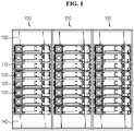
FIG. 1 is a diagram showing an energy storage system according to an embodiment of the present disclosure. -
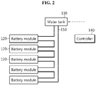
FIG. 2 is a diagram illustrating a connection structure between a water tank and battery modules and a relationship between the water tank and a controller in a battery pack according to an embodiment of the present disclosure. -
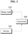
FIG. 3 is a diagram illustrating a relationship between a sensor, a controller and a water tank in a battery pack according to an embodiment of the present disclosure. -
FIGS. 4 and5 are perspective views showing a battery module that is applied to a battery pack according to an embodiment of the present disclosure. -
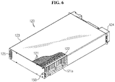
FIG. 6 is a diagram showing an internal structure of a battery module that is applied to a battery pack according to an embodiment of the present disclosure. -
FIG. 7 is a partial front view of a battery module that is applied to a battery pack according to an embodiment of the present disclosure, showing an expandable pad disposed in the battery module. -
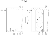
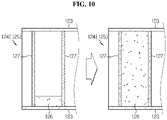
FIGS. 8 to 10 are partial cross-sectional views of a battery module that is applied to a battery pack according to an embodiment of the present disclosure when viewed from the side, showing an expandable pad disposed in the battery module. -
FIG. 11 is a diagram illustrating a connection structure between a water tank and battery modules, and a relationship between valves, a controller and the water tank in a battery pack according to another embodiment of the present disclosure. - Hereinafter, the preferred embodiments of the present disclosure will be described in detail with reference to the accompanying drawings. Prior to the description, it should be understood that the terms or words used in the specification and the appended claims should not be construed as being limited to general and dictionary meanings, but rather interpreted based on the meanings and concepts corresponding to the technical aspects of the present disclosure on the basis of the principle that the inventor is allowed to define the terms appropriately for the best explanation. Therefore, the embodiments described herein and illustrations shown in the drawings are just some preferred embodiment of the present disclosure, but not intended to fully describe the technical aspects of the present disclosure, so it should be understood that a variety of other equivalents and modifications could have been made thereto at the time that the application was filed.
- Referring to
FIG. 1 , an energy storage system according to an embodiment of the present disclosure includes a plurality ofbattery packs 100 according to an embodiment of the present disclosure. - Referring to
FIGS. 1 to 3 , thebattery pack 100 according to an embodiment of the present disclosure includes apack housing 110, abattery module 120, awater tank 130, acontroller 140, acooling water pipe 150 and asensor 160. - The
pack housing 110 is an approximately rectangular frame defining the shape of thebattery pack 100, and has a space in which a plurality ofbattery modules 120, thewater tank 130, thecontroller 140, thecooling water pipe 150 and thesensor 160 are installed. - The plurality of
battery modules 120 is provided, and the plurality ofbattery modules 120 is stacked on top of each other within thepack housing 110 to form a module stack. The detailed structure of thebattery module 120 will be described in detail below with reference toFIGS. 4 to 7 . - The
water tank 130 is provided in thepack housing 110 to store cooling water to be supplied to thebattery module 120 when thermal runaway occurs in thebattery module 120. Thewater tank 130 may be disposed on the module stack for quick and good supply of cooling water. In this case, cooling water may be supplied to thebattery module 120 quickly by a free fall and cooling water pressure without using a separate cooling water pump. For quicker and better supply of cooling water, a separate cooling water pump may be applied to thewater tank 130. - The
controller 140 may be connected to thesensor 160 and thewater tank 130 to output a control signal for opening thewater tank 130 in response to a sensing signal from thesensor 160. In addition to this function, thecontroller 140 may function as a battery management system (BMS) connected to each of thebattery modules 120 to manage the charge/discharge. - When gas or a temperature rise above a reference value is detected in the
battery pack 100 due to thermal runaway occurred in at least one of the plurality ofbattery modules 120, thecontroller 140 outputs a control signal for opening thewater tank 130 to supply cooling water to thebattery module 120. - When the
water tank 130 is open by the control signal of thecontroller 140, the cooling water is supplied in a sequential order from thetop battery module 120 to thebottom battery module 120. Accordingly, it is possible to put out the flames in thebattery module 120 and cool down thebattery module 120, thereby preventing the thermal runaway from propagating to theentire battery pack 100. - The
cooling water pipe 150 connects thewater tank 130 to thebattery module 120 and acts as a passage to transport the cooling water supplied from thewater tank 130 to thebattery module 120. To perform this function, one end of thecooling water pipe 150 is connected to the water tank, and the other end is divided into the number of branches corresponding to the number ofbattery modules 120, each branch connected to each of the plurality ofbattery modules 120. - As described above, when thermal runaway occurs in at least some of the plurality of
battery modules 120, thesensor 160 senses an increase in temperature and/or gas generation, and transmits a sensing signal to thecontroller 140. To perform this function, thesensor 160 may be a temperature sensor or a gas detection sensor, and a combination thereof. - The
sensor 160 is installed in thepack housing 110 to detect an increase in the internal temperature or gas generation in thebattery pack 100. Thesensor 160 may be attached to the inner or outer side of each of the plurality ofbattery modules 120 to quickly sense the temperature of thebattery module 120 and/or gas generated from thebattery module 120. - The
battery module 120 applied to thebattery pack 100 according to an embodiment of the present disclosure will be described in more detail below with reference toFIGS. 4 to 7 . - Referring to
FIGS. 4 to 7 , thebattery module 120 includes a plurality ofbattery cells 121, abusbar frame 122, amodule housing 123, anair inlet 124, anair outlet 125 and anexpandable pad 126. - The plurality of
battery cells 121 is provided, and the plurality ofbattery cells 121 is stacked to form a cell stack. Thebattery cell 121 may include, for example, a pouch type battery cell. Thebattery cell 121 has a pair of electrode leads 121a extending on two sides in the lengthwise direction respectively. - A pair of busbar frames 122 are provided, and the busbar frames 122 cover one side and the other side in the widthwise direction of the cell stack (the direction in which the electrode leads are formed) respectively. The electrode leads 121a of the
battery cell 121 extend through slits formed in the busbar frames 122, and they are bent and fixed onto the busbar frames 122 by welding. That is, the plurality ofbattery cells 121 may be electrically connected by the busbar frames 122. - The
module housing 123 has a substantially rectangular parallelepiped shape, and receives the cell stack inside. Theair inlet 124 and theair outlet 125 are formed on one side and the other side in the lengthwise direction of themodule housing 123. - When the
battery pack 100 of the present disclosure ofFIG. 1 is viewed from the front side, theair inlet 124 is formed on one side (front side) in the stack direction of the cell stack, i.e., one side in the lengthwise direction of thebattery module 120. Theair inlet 124 is formed in the shape of a hole passing through themodule housing 123. Theair outlet 125 is formed on the other side (rear side) in the stack direction of the cell stack, i.e., the other side in the lengthwise direction of thebattery module 120. Theair outlet 125 is formed in the shape of a hole passing through themodule housing 123. - The
air inlet 124 and theair outlet 125 are disposed on the opposite sides diagonally across thebattery module 120 along the lengthwise direction (the stack direction of the cell stack). - Meanwhile, an empty space is formed between the busbar frames 122 and the
module housing 123. That is, an empty space in which air for cooling thebattery cells 121 flows is formed between the busbar frames 122 and the surfaces corresponding to one side and the opposite side in the lengthwise direction of thebattery cell 121 among the six outer sides of themodule housing 123. The empty space is formed on each of the two sides in the widthwise direction of thebattery module 120. - The
air inlet 124 is formed at a location corresponding to the empty space formed on one side in the widthwise direction of thebattery module 120, and theair outlet 125 is formed at a location corresponding to the empty space formed on the other side in the widthwise direction of thebattery module 120. - In the
battery module 120, air introduced through theair inlet 124 exits theair outlet 125 after cooling down thebattery cell 121 while moving from the empty space formed on one side in the widthwise direction of thebattery module 120 to the empty space formed on the other side in the widthwise direction of thebattery module 120. That is, thebattery module 120 is of an air-cooled type. - The cooling
water pipe 150 is in communication with the empty space formed between the busbar frames 122 and themodule housing 123 through themodule housing 123 from one side or the other side in the stack direction of the cell stack. That is, the coolingwater pipe 150 may be inserted through the same surface as the surface in which theair inlet 124 is formed or the surface in which theair outlet 125 is formed among the six surfaces of themodule housing 123. - Accordingly, cooling water introduced into the
battery module 120 through the coolingwater pipe 150 flows from the empty space formed on one side in the widthwise direction of thebattery module 120 to the empty space formed on the other side in the widthwise direction of thebattery module 120 as shown inFIGS. 4 and5 , and thebattery module 120 is filled with the cooling water. - Referring to
FIG. 7 , theexpandable pad 126 is disposed inside of theair inlet 124 and theair outlet 125. Theexpandable pad 126 is attached to the inner surface of themodule housing 123, and having a size smaller than the open area of theair inlet 124 and theair outlet 125. To improve the air flow through theair inlet 124 and the air outlet in the normal condition of thebattery module 120, theexpandable pad 126 preferably has a size of less than about 30% of the open area of theair inlet 124 and theair outlet 125. AlthoughFIG. 6 shows that theexpandable pad 126 is attached to the bottom of themodule housing 123, theexpandable pad 126 may be attached to the top or the side of themodule housing 123. - The
expandable pad 126 expands when it contacts cooling water introduced into thebattery module 120, and theair inlet 124 and theair outlet 125 are closed by the expansion of theexpandable pad 126. Theexpandable pad 126 contains resin that exhibits a very large expansion rate when the resin absorbs moisture, and when a sufficient amount of moisture is provided, the volume of the resin is larger at least two times than the initial volume. The resin used for theexpandable pad 126 may include, for example, a nonwoven fabric formed from a mixture of super absorbent fibers (SAFs) and polyester staple fibers. The SAF is a fiber made of super absorbent polymer (SAP). - The closing of the
air inlet 124 and theair outlet 125 by the expansion of theexpandable pad 126 is not necessarily limited to complete closure of theinlet 124 and theair outlet 125 to prevent cooling water leaks, and encompasses a reduction in the open area of theinlet 124 and theair outlet 125 to reduce cooling water leaks. - By the use of the
expandable pad 126, when cooling water is introduced into thebattery module 120 in the event that thermal runaway occurs in at least some of thebattery modules 120, theair inlet 124 and theair outlet 125 are closed. When theair inlet 124 and theair outlet 125 are closed, the cooling water introduced into thebattery module 120 does not leak and stays in thebattery module 120, thereby quickly solving the problem of thermal runaway occurred in thebattery module 120. - Referring to
FIG. 8 , a pair ofexpandable pads 126 may be provided, and in this case, the pair ofexpandable pads 126 are attached to the upper and lower inner surfaces of themodule housing 123 respectively. The pair ofexpandable pads 126 are attached at matching locations to close theair inlet 124 and theair outlet 125 when they come into contact with each other by expansion. - Referring to
FIG. 9 , at least part of theexpandable pad 126 may be inserted and fixed into a receiving groove G formed at a predetermined depth in the inner surface of themodule housing 123. - Referring to
FIG. 10 , when theexpandable pad 126 expands upon moisture absorption, movement for expansion may be guided by a pair ofmesh plates 127 disposed on two sides respectively. Themesh plate 127 is a mesh type plate having a structure that allows air and cooling water to pass therethrough in a non-expanded condition of theexpandable pad 126. - A battery pack according to another embodiment of the present disclosure will be described below with reference to
FIG. 11 . - The battery pack according to another embodiment of the present disclosure is substantially the same as the
battery pack 100 according to an embodiment of the present disclosure as described above, but only different invalves 170 installed in the coolingwater pipe 150. - Accordingly, in describing the battery pack according to another embodiment of the present disclosure, a detailed description of the
valves 170 is provided below, and redundant descriptions are omitted herein. - The plurality of
valves 170 corresponding to the number ofbattery modules 120 is provided, and eachvalve 170 is installed adjacent to the plurality ofbattery modules 120 to individually allow or block the flow of cooling water introduced into the plurality ofbattery modules 120. - To independently operate the plurality of
valves 170, at least onesensor 160 is provided for eachbattery module 120. When thesensor 160 is provided for eachbattery module 120, it is possible to introduce cooling water into only thebattery module 120 in which thermal runaway occurred. - That is, when the
controller 140 receives a detection signal from acertain sensor 160, thecontroller 140 determines that thermal runaway occurred in thebattery module 120 to which thesensor 160 having transmitted the detection signal is attached, and opens thevalve 170 installed adjacent to thebattery module 120 in which thermal runaway occurred among the plurality ofvalves 170 to introduce cooling water into thebattery module 120. - As described above, in the battery pack according to the present disclosure, when thermal runaway occurs in the
battery module 120, cooling water is introduced into thebattery module 120, thereby preventing the thermal runaway from propagating toadjacent battery modules 120. Particularly, in the battery pack according to the present disclosure, when cooling water is introduced into the air-cooledbattery module 120, theair inlet 124 and theair outlet 125 are closed to fill thebattery module 120 with cooling water, thereby preventing thermal runaway propagation more effectively. - While the present disclosure has been hereinabove described with regard to a limited number of embodiments and drawings, the present disclosure is not limited thereto and it is obvious to those skilled in the art that various modifications and changes may be made thereto within the technical aspects of the present disclosure and the equivalent scope of the appended claims.
Claims (12)
- A battery module comprising:a plurality of battery cells;a module housing in which a cell stack is received, the cell stack being formed by stacking the plurality of battery cells;an air inlet passing through the module housing on one side of a stack direction of the cell stack;an air outlet passing through the module housing on the other side in the stack direction of the cell stack; andan expandable pad disposed inside of the air inlet and the air outlet to close the air inlet and the air outlet by expansion upon contact with cooling water introduced into the module housing.
- The battery module according to claim 1, wherein the expandable pad is attached to an inner surface of the module housing.
- The battery module according to claim 1, wherein a pair of expandable pads are provided, and
the pair of expandable pads are attached to upper and lower inner surfaces of the module housing respectively. - The battery module according to claim 1, wherein at least part of the expandable pad is inserted into a receiving groove formed in an inner surface of the module housing.
- The battery module according to claim 1, wherein the battery module includes a mesh plate disposed on each of two sides of the expandable pad to guide movement for expansion of the expandable pad.
- The battery module according to claim 1, wherein the battery module includes a pair of busbar frames coupled to one side and the other side in a widthwise direction of the cell stack respectively.
- The battery module according to claim 6, wherein the air inlet and the air outlet are formed at locations corresponding to an empty space between the busbar frames and the module housing.
- A battery pack comprising:a pack housing;a plurality of battery modules according to claim 1, stacked in the pack housing;a water tank disposed on a module stack including the plurality of battery modules to store cooling water;a cooling water pipe connecting the water tank to the battery modules;at least one sensor installed in the pack housing to detect thermal runaway occurring in a certain battery module among the plurality of battery modules; anda controller to output a control signal to introduce the cooling water into the battery module through the cooling water pipe when the thermal runaway is detected by the sensor.
- The battery pack according to claim 8, wherein the battery pack includes a plurality of valves installed in the cooling water pipe, and
each of the plurality of valves is installed adjacent to the plurality of battery modules to individually allow or block a flow of the cooling water introduced into the plurality of battery modules. - The battery pack according to claim 9, wherein the sensor is installed in each of the plurality of battery modules.
- The battery pack according to claim 10, wherein the controller outputs a control signal to open the valve installed adjacent to the battery module in which the thermal runaway is detected by the sensor among the plurality of valves.
- An energy storage system comprising a plurality of battery packs according to claim 8.
Applications Claiming Priority (2)
| Application Number | Priority Date | Filing Date | Title |
|---|---|---|---|
| KR1020190082288A KR102791885B1 (en) | 2019-07-08 | 2019-07-08 | Battery Module Having Structure Into Which Cooling Water Can Be Introduced When Thermal Runaway Occurs, Battery Pack and Energy Storage System Comprising The Same |
| PCT/KR2020/008737 WO2021006560A1 (en) | 2019-07-08 | 2020-07-03 | Battery module having structure into which cooling water can be introduced when thermal runaway phenomenon occurs, and battery pack and energy storage device comprising same |
Publications (2)
| Publication Number | Publication Date |
|---|---|
| EP3989336A1 true EP3989336A1 (en) | 2022-04-27 |
| EP3989336A4 EP3989336A4 (en) | 2022-11-16 |
Family
ID=74114266
Family Applications (1)
| Application Number | Title | Priority Date | Filing Date |
|---|---|---|---|
| EP20837142.7A Pending EP3989336A4 (en) | 2019-07-08 | 2020-07-03 | BATTERY MODULE HAVING A STRUCTURE INTO WHICH COOLING WATER CAN BE INTRODUCED WHEN A THERMAL RUNAWAY PHENOMENON OCCURS, AND BATTERY PACK AND ENERGY STORAGE DEVICE COMPRISING THE SAME |
Country Status (5)
| Country | Link |
|---|---|
| US (1) | US12224419B2 (en) |
| EP (1) | EP3989336A4 (en) |
| JP (1) | JP7358609B2 (en) |
| KR (1) | KR102791885B1 (en) |
| WO (1) | WO2021006560A1 (en) |
Cited By (2)
| Publication number | Priority date | Publication date | Assignee | Title |
|---|---|---|---|---|
| EP4024590A4 (en) * | 2020-02-17 | 2023-01-04 | Lg Energy Solution, Ltd. | BATTERY MODULE HAVING A STRUCTURE CAPABLE OF DELAYING THE FLOW OF FIRE FIGHTING WATER INJECTED THEREOF IN THE EVENT OF FIRE, AND BATTERY FRAME, AND ENERGY STORAGE DEVICE COMPRISING THE SAME |
| EP4478475A4 (en) * | 2022-06-14 | 2025-09-24 | Lg Energy Solution Ltd | BATTERY PACK WITH IMPROVED FIRE SAFETY |
Families Citing this family (9)
| Publication number | Priority date | Publication date | Assignee | Title |
|---|---|---|---|---|
| CN115668607A (en) * | 2021-01-28 | 2023-01-31 | 株式会社Lg新能源 | Battery module with improved fire protection |
| KR102718427B1 (en) * | 2021-02-02 | 2024-10-16 | 주식회사 엘지에너지솔루션 | A battery module having a guide wing to induce fire extinguishing agent into a battery cell unit and battery rack comprising the same and energy storage system comprising the same |
| WO2022177210A1 (en) * | 2021-02-19 | 2022-08-25 | 주식회사 엘지에너지솔루션 | Electric vehicle underbody having water tank |
| KR102919208B1 (en) | 2021-03-23 | 2026-01-27 | 주식회사 엘지에너지솔루션 | A battery module with a heat propagation repression structure using coolant and a battery pack including the same |
| CN216354424U (en) * | 2021-11-12 | 2022-04-19 | 宁德时代新能源科技股份有限公司 | Thermal management system for energy storage device and energy storage device |
| KR20230107041A (en) | 2022-01-07 | 2023-07-14 | 주식회사 엘지에너지솔루션 | A Battery Pack Equipped With A Heat Diffusion Prevention Function |
| KR20230107040A (en) | 2022-01-07 | 2023-07-14 | 주식회사 엘지에너지솔루션 | A Battery Pack Equipped With A Heat Diffusion Prevention Function |
| KR20230107039A (en) | 2022-01-07 | 2023-07-14 | 주식회사 엘지에너지솔루션 | A Battery Pack Equipped With A Heat Diffusion Prevention Function |
| CN115693852B (en) * | 2022-10-31 | 2026-01-09 | 华为数字能源技术有限公司 | An energy storage system and a power supply system |
Family Cites Families (26)
| Publication number | Priority date | Publication date | Assignee | Title |
|---|---|---|---|---|
| DE102008011466A1 (en) * | 2008-02-27 | 2009-09-03 | Robert Bosch Gmbh | battery module |
| JP5284181B2 (en) | 2009-05-29 | 2013-09-11 | タイガースポリマー株式会社 | Battery cooling structure |
| JP5856472B2 (en) | 2011-12-22 | 2016-02-09 | 積水化学工業株式会社 | Storage battery installation structure |
| JP6041252B2 (en) | 2012-03-09 | 2016-12-07 | 日産自動車株式会社 | Air battery cartridge and air battery system |
| JP5880847B2 (en) | 2012-04-25 | 2016-03-09 | 三菱自動車工業株式会社 | Battery device |
| JP5953925B2 (en) | 2012-05-15 | 2016-07-20 | 三菱自動車工業株式会社 | Battery energy release device |
| JP6061745B2 (en) | 2013-03-21 | 2017-01-18 | 大阪瓦斯株式会社 | Polymer electrolyte fuel cell |
| JP2014216248A (en) | 2013-04-26 | 2014-11-17 | 三菱自動車工業株式会社 | Battery case |
| JP3187696U (en) | 2013-09-10 | 2013-12-12 | 株式会社ヴィド久米島 | Air battery |
| JP2015141833A (en) | 2014-01-29 | 2015-08-03 | トヨタ自動車株式会社 | Battery pack cooling device |
| KR102172846B1 (en) * | 2014-02-10 | 2020-11-02 | 삼성에스디아이 주식회사 | Battery pack |
| JP2015153616A (en) * | 2014-02-14 | 2015-08-24 | 株式会社オートネットワーク技術研究所 | Battery pack |
| US20160093842A1 (en) | 2014-09-30 | 2016-03-31 | Google Inc. | Battery module |
| KR102553028B1 (en) * | 2016-01-12 | 2023-07-06 | 삼성전자주식회사 | Battery pack for uniform cooling of modules and cooling method thereof |
| KR102179537B1 (en) * | 2016-07-12 | 2020-11-16 | 주식회사 엘지화학 | Battery pack |
| CN106571503A (en) * | 2016-11-11 | 2017-04-19 | 华中科技大学 | Electric automobile battery module thermorunaway safety fire extinguishing system and method |
| JP2019535516A (en) | 2016-11-15 | 2019-12-12 | 8 リバーズ キャピタル,エルエルシー | Removal of impurities from process streams by contact with oxidants and water streams |
| JP2018098074A (en) | 2016-12-14 | 2018-06-21 | 三菱自動車工業株式会社 | Battery pack |
| JP2018133134A (en) | 2017-02-13 | 2018-08-23 | 三菱自動車工業株式会社 | Secondary battery cooling mechanism |
| KR102273194B1 (en) | 2017-07-19 | 2021-07-05 | 주식회사 엘지에너지솔루션 | Apparatus for cooling of battery and battery pack including the same |
| JP6848752B2 (en) | 2017-07-27 | 2021-03-24 | トヨタ自動車株式会社 | Power storage module |
| KR102378539B1 (en) * | 2017-12-06 | 2022-03-23 | 주식회사 엘지에너지솔루션 | Cell edge direct cooling type Battery module and Battery pack including the same |
| CN109546261B (en) | 2018-11-19 | 2024-06-11 | 浙江南都电源动力股份有限公司 | Battery thermal management system of container type energy storage system |
| CN209859997U (en) | 2019-03-22 | 2019-12-27 | 中国电力科学研究院有限公司 | Battery box and energy storage battery cabinet with fire protection structure |
| AU2020282883B2 (en) | 2019-05-30 | 2025-09-04 | Lg Energy Solution, Ltd. | Battery module having path through which internally supplied coolant can flow when thermal runaway occurs, and battery pack and ESS including same |
| CN110212132B (en) * | 2019-06-25 | 2021-09-17 | 江苏快乐电源(涟水)有限公司 | Battery pack with function of removing moisture in air inside battery box |
-
2019
- 2019-07-08 KR KR1020190082288A patent/KR102791885B1/en active Active
-
2020
- 2020-07-03 EP EP20837142.7A patent/EP3989336A4/en active Pending
- 2020-07-03 JP JP2022500978A patent/JP7358609B2/en active Active
- 2020-07-03 US US17/625,561 patent/US12224419B2/en active Active
- 2020-07-03 WO PCT/KR2020/008737 patent/WO2021006560A1/en not_active Ceased
Cited By (3)
| Publication number | Priority date | Publication date | Assignee | Title |
|---|---|---|---|---|
| EP4024590A4 (en) * | 2020-02-17 | 2023-01-04 | Lg Energy Solution, Ltd. | BATTERY MODULE HAVING A STRUCTURE CAPABLE OF DELAYING THE FLOW OF FIRE FIGHTING WATER INJECTED THEREOF IN THE EVENT OF FIRE, AND BATTERY FRAME, AND ENERGY STORAGE DEVICE COMPRISING THE SAME |
| US12294109B2 (en) | 2020-02-17 | 2025-05-06 | Lg Energy Solution, Ltd. | Battery module having structure capable of delaying outflow of fire-fighting water injected therein in case of fire, and battery rack and energy storage device comprising same |
| EP4478475A4 (en) * | 2022-06-14 | 2025-09-24 | Lg Energy Solution Ltd | BATTERY PACK WITH IMPROVED FIRE SAFETY |
Also Published As
| Publication number | Publication date |
|---|---|
| WO2021006560A1 (en) | 2021-01-14 |
| US12224419B2 (en) | 2025-02-11 |
| KR20210006570A (en) | 2021-01-19 |
| US20220294052A1 (en) | 2022-09-15 |
| EP3989336A4 (en) | 2022-11-16 |
| JP2022540461A (en) | 2022-09-15 |
| KR102791885B1 (en) | 2025-04-04 |
| JP7358609B2 (en) | 2023-10-10 |
Similar Documents
| Publication | Publication Date | Title |
|---|---|---|
| US12224419B2 (en) | Battery module having structure into which cooling water can be introduced when thermal runaway phenomenon occurs, and battery pack and energy storage device comprising same | |
| JP7179150B2 (en) | A battery module, a battery pack including the same, and an ESS having a path through which cooling water can flow when a thermal runaway phenomenon occurs | |
| EP4024590B1 (en) | Battery module having structure capable of delaying outflow of fire-fighting water injected therein in case of fire, and battery rack and energy storage device comprising same | |
| JP7480285B2 (en) | Battery pack having a structure capable of injecting cooling water into a battery module when a thermal runaway phenomenon occurs, and energy storage system including the same | |
| KR102882553B1 (en) | Battery module having a structure capable of rapid cooling and the Energy Storage System comprising the same | |
| KR102380446B1 (en) | A battery pack having a structure in which cooling water can be introduced into the battery module when a thermal runaway occurs and Energy storage system comprising the same | |
| KR102380444B1 (en) | A battery module having a path through which cooling water introduced therein can flow when a thermal runaway occurs, a battery pack and ESS comprising the same | |
| KR102886572B1 (en) | Battery module having a structure that allows the sprinkler to operate quickly and the Energy Storage System comprising the same | |
| JP7345628B2 (en) | A battery module having a structure that allows rapid cooling and an energy storage system including the same |
Legal Events
| Date | Code | Title | Description |
|---|---|---|---|
| STAA | Information on the status of an ep patent application or granted ep patent |
Free format text: STATUS: THE INTERNATIONAL PUBLICATION HAS BEEN MADE |
|
| PUAI | Public reference made under article 153(3) epc to a published international application that has entered the european phase |
Free format text: ORIGINAL CODE: 0009012 |
|
| STAA | Information on the status of an ep patent application or granted ep patent |
Free format text: STATUS: REQUEST FOR EXAMINATION WAS MADE |
|
| 17P | Request for examination filed |
Effective date: 20220121 |
|
| AK | Designated contracting states |
Kind code of ref document: A1 Designated state(s): AL AT BE BG CH CY CZ DE DK EE ES FI FR GB GR HR HU IE IS IT LI LT LU LV MC MK MT NL NO PL PT RO RS SE SI SK SM TR |
|
| DAV | Request for validation of the european patent (deleted) | ||
| DAX | Request for extension of the european patent (deleted) | ||
| A4 | Supplementary search report drawn up and despatched |
Effective date: 20221013 |
|
| RIC1 | Information provided on ipc code assigned before grant |
Ipc: A62C 2/06 20060101ALI20221007BHEP Ipc: H01M 10/63 20140101ALI20221007BHEP Ipc: H01M 10/48 20060101ALI20221007BHEP Ipc: H01M 10/613 20140101ALI20221007BHEP Ipc: H01M 10/627 20140101ALI20221007BHEP Ipc: H01M 10/6567 20140101AFI20221007BHEP |