EP3989333A1 - Battery module comprising cell frame - Google Patents
Battery module comprising cell frame Download PDFInfo
- Publication number
- EP3989333A1 EP3989333A1 EP20858696.6A EP20858696A EP3989333A1 EP 3989333 A1 EP3989333 A1 EP 3989333A1 EP 20858696 A EP20858696 A EP 20858696A EP 3989333 A1 EP3989333 A1 EP 3989333A1
- Authority
- EP
- European Patent Office
- Prior art keywords
- cooling
- battery module
- coolant
- module according
- battery cells
- Prior art date
- Legal status (The legal status is an assumption and is not a legal conclusion. Google has not performed a legal analysis and makes no representation as to the accuracy of the status listed.)
- Pending
Links
Images


Classifications
-
- H—ELECTRICITY
- H01—ELECTRIC ELEMENTS
- H01M—PROCESSES OR MEANS, e.g. BATTERIES, FOR THE DIRECT CONVERSION OF CHEMICAL ENERGY INTO ELECTRICAL ENERGY
- H01M10/00—Secondary cells; Manufacture thereof
- H01M10/60—Heating or cooling; Temperature control
- H01M10/65—Means for temperature control structurally associated with the cells
- H01M10/655—Solid structures for heat exchange or heat conduction
- H01M10/6556—Solid parts with flow channel passages or pipes for heat exchange
- H01M10/6557—Solid parts with flow channel passages or pipes for heat exchange arranged between the cells
-
- H—ELECTRICITY
- H01—ELECTRIC ELEMENTS
- H01M—PROCESSES OR MEANS, e.g. BATTERIES, FOR THE DIRECT CONVERSION OF CHEMICAL ENERGY INTO ELECTRICAL ENERGY
- H01M10/00—Secondary cells; Manufacture thereof
- H01M10/60—Heating or cooling; Temperature control
- H01M10/61—Types of temperature control
- H01M10/613—Cooling or keeping cold
-
- H—ELECTRICITY
- H01—ELECTRIC ELEMENTS
- H01M—PROCESSES OR MEANS, e.g. BATTERIES, FOR THE DIRECT CONVERSION OF CHEMICAL ENERGY INTO ELECTRICAL ENERGY
- H01M10/00—Secondary cells; Manufacture thereof
- H01M10/60—Heating or cooling; Temperature control
- H01M10/62—Heating or cooling; Temperature control specially adapted for specific applications
- H01M10/625—Vehicles
-
- H—ELECTRICITY
- H01—ELECTRIC ELEMENTS
- H01M—PROCESSES OR MEANS, e.g. BATTERIES, FOR THE DIRECT CONVERSION OF CHEMICAL ENERGY INTO ELECTRICAL ENERGY
- H01M10/00—Secondary cells; Manufacture thereof
- H01M10/60—Heating or cooling; Temperature control
- H01M10/64—Heating or cooling; Temperature control characterised by the shape of the cells
- H01M10/643—Cylindrical cells
-
- H—ELECTRICITY
- H01—ELECTRIC ELEMENTS
- H01M—PROCESSES OR MEANS, e.g. BATTERIES, FOR THE DIRECT CONVERSION OF CHEMICAL ENERGY INTO ELECTRICAL ENERGY
- H01M10/00—Secondary cells; Manufacture thereof
- H01M10/60—Heating or cooling; Temperature control
- H01M10/65—Means for temperature control structurally associated with the cells
- H01M10/653—Means for temperature control structurally associated with the cells characterised by electrically insulating or thermally conductive materials
-
- H—ELECTRICITY
- H01—ELECTRIC ELEMENTS
- H01M—PROCESSES OR MEANS, e.g. BATTERIES, FOR THE DIRECT CONVERSION OF CHEMICAL ENERGY INTO ELECTRICAL ENERGY
- H01M10/00—Secondary cells; Manufacture thereof
- H01M10/60—Heating or cooling; Temperature control
- H01M10/65—Means for temperature control structurally associated with the cells
- H01M10/655—Solid structures for heat exchange or heat conduction
- H01M10/6556—Solid parts with flow channel passages or pipes for heat exchange
-
- H—ELECTRICITY
- H01—ELECTRIC ELEMENTS
- H01M—PROCESSES OR MEANS, e.g. BATTERIES, FOR THE DIRECT CONVERSION OF CHEMICAL ENERGY INTO ELECTRICAL ENERGY
- H01M10/00—Secondary cells; Manufacture thereof
- H01M10/60—Heating or cooling; Temperature control
- H01M10/65—Means for temperature control structurally associated with the cells
- H01M10/656—Means for temperature control structurally associated with the cells characterised by the type of heat-exchange fluid
- H01M10/6561—Gases
- H01M10/6562—Gases with free flow by convection only
-
- H—ELECTRICITY
- H01—ELECTRIC ELEMENTS
- H01M—PROCESSES OR MEANS, e.g. BATTERIES, FOR THE DIRECT CONVERSION OF CHEMICAL ENERGY INTO ELECTRICAL ENERGY
- H01M10/00—Secondary cells; Manufacture thereof
- H01M10/60—Heating or cooling; Temperature control
- H01M10/65—Means for temperature control structurally associated with the cells
- H01M10/656—Means for temperature control structurally associated with the cells characterised by the type of heat-exchange fluid
- H01M10/6567—Liquids
-
- H—ELECTRICITY
- H01—ELECTRIC ELEMENTS
- H01M—PROCESSES OR MEANS, e.g. BATTERIES, FOR THE DIRECT CONVERSION OF CHEMICAL ENERGY INTO ELECTRICAL ENERGY
- H01M50/00—Constructional details or processes of manufacture of the non-active parts of electrochemical cells other than fuel cells, e.g. hybrid cells
- H01M50/20—Mountings; Secondary casings or frames; Racks, modules or packs; Suspension devices; Shock absorbers; Transport or carrying devices; Holders
- H01M50/204—Racks, modules or packs for multiple batteries or multiple cells
- H01M50/207—Racks, modules or packs for multiple batteries or multiple cells characterised by their shape
- H01M50/213—Racks, modules or packs for multiple batteries or multiple cells characterised by their shape adapted for cells having curved cross-section, e.g. round or elliptic
-
- H—ELECTRICITY
- H01—ELECTRIC ELEMENTS
- H01M—PROCESSES OR MEANS, e.g. BATTERIES, FOR THE DIRECT CONVERSION OF CHEMICAL ENERGY INTO ELECTRICAL ENERGY
- H01M50/00—Constructional details or processes of manufacture of the non-active parts of electrochemical cells other than fuel cells, e.g. hybrid cells
- H01M50/20—Mountings; Secondary casings or frames; Racks, modules or packs; Suspension devices; Shock absorbers; Transport or carrying devices; Holders
- H01M50/258—Modular batteries; Casings provided with means for assembling
-
- H—ELECTRICITY
- H01—ELECTRIC ELEMENTS
- H01M—PROCESSES OR MEANS, e.g. BATTERIES, FOR THE DIRECT CONVERSION OF CHEMICAL ENERGY INTO ELECTRICAL ENERGY
- H01M50/00—Constructional details or processes of manufacture of the non-active parts of electrochemical cells other than fuel cells, e.g. hybrid cells
- H01M50/20—Mountings; Secondary casings or frames; Racks, modules or packs; Suspension devices; Shock absorbers; Transport or carrying devices; Holders
- H01M50/271—Lids or covers for the racks or secondary casings
-
- H—ELECTRICITY
- H01—ELECTRIC ELEMENTS
- H01M—PROCESSES OR MEANS, e.g. BATTERIES, FOR THE DIRECT CONVERSION OF CHEMICAL ENERGY INTO ELECTRICAL ENERGY
- H01M50/00—Constructional details or processes of manufacture of the non-active parts of electrochemical cells other than fuel cells, e.g. hybrid cells
- H01M50/20—Mountings; Secondary casings or frames; Racks, modules or packs; Suspension devices; Shock absorbers; Transport or carrying devices; Holders
- H01M50/289—Mountings; Secondary casings or frames; Racks, modules or packs; Suspension devices; Shock absorbers; Transport or carrying devices; Holders characterised by spacing elements or positioning means within frames, racks or packs
- H01M50/291—Mountings; Secondary casings or frames; Racks, modules or packs; Suspension devices; Shock absorbers; Transport or carrying devices; Holders characterised by spacing elements or positioning means within frames, racks or packs characterised by their shape
-
- H—ELECTRICITY
- H01—ELECTRIC ELEMENTS
- H01M—PROCESSES OR MEANS, e.g. BATTERIES, FOR THE DIRECT CONVERSION OF CHEMICAL ENERGY INTO ELECTRICAL ENERGY
- H01M2220/00—Batteries for particular applications
- H01M2220/20—Batteries in motive systems, e.g. vehicle, ship, plane
-
- Y—GENERAL TAGGING OF NEW TECHNOLOGICAL DEVELOPMENTS; GENERAL TAGGING OF CROSS-SECTIONAL TECHNOLOGIES SPANNING OVER SEVERAL SECTIONS OF THE IPC; TECHNICAL SUBJECTS COVERED BY FORMER USPC CROSS-REFERENCE ART COLLECTIONS [XRACs] AND DIGESTS
- Y02—TECHNOLOGIES OR APPLICATIONS FOR MITIGATION OR ADAPTATION AGAINST CLIMATE CHANGE
- Y02E—REDUCTION OF GREENHOUSE GAS [GHG] EMISSIONS, RELATED TO ENERGY GENERATION, TRANSMISSION OR DISTRIBUTION
- Y02E60/00—Enabling technologies; Technologies with a potential or indirect contribution to GHG emissions mitigation
- Y02E60/10—Energy storage using batteries
Definitions
- the present disclosure relates to a battery module comprising a cell frame, and more particularly, to a battery module having the increased operating life by efficiently maintaining the heat balance.
- the lithium secondary battery mainly uses lithium-based oxide and a carbon material for a positive electrode active material and a negative electrode active material respectively.
- the lithium secondary battery includes an electrode assembly including a positive electrode plate coated with the positive electrode active material, a negative electrode plate coated with the negative electrode active material and a separator interposed between, and a hermetically sealed packaging material or battery pouch case in which the electrode assembly is received together with an electrolyte solution.
- secondary batteries are being widely used in not only small devices such as portable electronic products but also medium- and large-scale devices such as vehicles and energy storage systems (ESSs).
- ESSs vehicles and energy storage systems
- many secondary batteries are electrically connected to increase the capacity and output.
- pouch-type secondary batteries are widely used in medium- and large-scale devices because they are easy to stack.
- a battery module including a plurality of secondary batteries electrically connected in series and/or in parallel and a metal plate electrically connecting the secondary batteries.
- the battery module generally uses cooling technology to prevent the rapid temperature rise of the secondary batteries during use. For example, it is general to cool the received secondary batteries by feeding cold air into a housing of the battery module.
- the cooling effect concentrates on some secondary batteries and the cooling effect on the remaining secondary batteries is low, so overheat may occur in some secondary batteries. That is, in case that heat imbalance occurs, when some of secondary batteries are placed in high temperature condition, degradation occurs, and the life of some secondary batteries may greatly reduce, which may be the main factor that reduces the life of the battery module.
- the present disclosure is designed to solve the above-described problem, and therefore the present disclosure is directed to providing a battery module having the increased operational life by efficiently maintaining the heat balance.
- a battery module includes a plurality of cylindrical battery cells including an electrode terminal formed in each of an upper end and a lower end, and arranged in a horizontal direction, a module housing including an upper wall, a sidewall and a lower wall to receive the plurality of cylindrical battery cells, at least one of the upper wall or the lower wall having a plurality of cooling holes through the coolant flows in and out, at least two of the cooling holes having different sizes, and a cell frame received in the module housing and including an insertion portion having an inner wall to wrap around at least part of an outer surface of each of the plurality of cylindrical battery cells, and a plurality of cooling passages connected to the cooling holes in communication with the cooling holes and having a tubular shape extending in a vertical direction to allow the coolant to flow in and out.
- At least two of the plurality of cooling holes may be configured such that a cooling hole closer to a center has a larger diameter than a cooling hole disposed at an outer side.
- the cooling passage may have a size corresponding to a diameter of the cooling hole in communication with the cooling passage.
- the plurality of cylindrical battery cells may be spaced apart from each other to allow the coolant to flow.
- the cell frame may include an upper case including the plurality of insertion portions and the plurality of cooling passages, and a lower case coupled to bottom of the upper case and including the plurality of insertion portions and the plurality of cooling passages.
- the plurality of cooling passages of the upper case and the plurality of cooling passages of the lower case may be disposed corresponding to each other in the vertical direction, and the plurality of cooling passages of the upper case and the plurality of cooling passages of the lower case may be spaced apart from each other in the vertical direction.
- the plurality of cooling holes in the upper wall of the module housing may be configured to allow the coolant to flow from outside to inside, and the plurality of cooling holes provided in the lower wall of the module housing may be configured to force the coolant fed into the module housing out.
- cooling passages of the upper case may include a guide portion configured to change a flow direction of the coolant to a horizontal inward direction of the plurality of cylindrical battery cells.
- the guide portion may include a guide protrusion extending in the horizontal inward direction of the plurality of cylindrical battery cells.
- the guide portion may have a bent structure in which the cooling passages of the upper case are bent in the horizontal inward direction of the plurality of cylindrical battery cells.
- the plurality of cooling holes provided in the upper wall of the module housing may include a tapered structure having an inner diameter gradually decreasing in the horizontal inward direction.
- the plurality of cooling holes provided in the lower wall of the module housing may include a tapered structure having an inner diameter gradually decreasing in a vertical outward direction.
- the cooling passage may have an outer end extending in the vertical direction from an outer surface of the cell frame, and the cell frame may have an exposure hole to expose the electrode terminal to the outside.
- the battery module may further include a connection hole mounted on each of the upper and lower parts of the cell frame, the connection hole in communication with the exposure hole, a connection terminal extending from an inner side of the connection hole to electrically connect the plurality of cylindrical battery cells, and at least one connecting plate having an insertion groove in which the end of the cooling passage is inserted.
- each of an upper surface and a lower surface of the cell frame may have a partition wall extending in an outward direction and extending linearly in the horizontal direction, of which part connects the plurality of cooling passages, and the partition wall may be disposed corresponding to an outer periphery of the connecting plate in the horizontal direction.
- the battery module may further include a thermally conductive pad mounted on an outer side of the connecting plate and including a fixing groove into which the cooling passage is inserted, and a heat sink the mounted on an outer side of the thermally conductive pad and including a fixing hole into which the cooling passage is inserted.
- a battery pack according to the present disclosure includes at least one battery module.
- an electronic device includes the battery pack.
- the battery module of the present disclosure is configured such that at least two of the plurality of cooling holes provided in the module housing have different sizes, to increase the amount of the flow of coolant in an area where cooling is required, thereby adjusting the temperature for each area inside the battery module. Accordingly, it is possible to prevent overheat at a specific area of the battery module.
- the cell frame of the present disclosure includes the plurality of cooling passages configured to be in communication with the cooling holes, heat of the coolant flowing into the cooling holes may be effectively transmitted to the plurality of cylindrical battery cells received in the insertion portion.
- the present disclosure may protect the plurality of cylindrical battery cells from external impacts by the module housing and the cell frame, and supply the coolant supplied from the outside to the plurality of cylindrical battery cells, thereby greatly increasing the cooling efficiency.
- the present disclosure is configured such that among at least two of the plurality of cooling holes provided in the lower wall of the module housing, the cooling hole closer to the center has a larger diameter than the cooling hole disposed at the outer side, so that a larger amount of coolant may be fed into the lower wall of the module housing or a larger amount of coolants fed into the module housing may be forced out as it is closer to the horizontal center of the module housing.
- At least two of the plurality of cooling holes provided in the upper wall of the module housing are configured such that the cooling hole closer to the center has a larger diameter than the cooling hole disposed at the outer side, so that a larger amount of coolants may be fed into the upper wall of the module housing or a larger amount of coolants fed into the module housing may be forced out as it is closer to the horizontal center of the module housing.
- the cooling passage is configured to have the size corresponding to the dimeter of the cooling hole in communication with the cooling passage, to allow the coolant flowing in through the cooling hole of the module housing to move along the cooling passage without interruption, thereby increasing the cooling efficiency.
- the plurality of cylindrical battery cells may be spaced apart from each other to allow the coolant to flow, and thus the present disclosure may allow the coolant to flow in the gap well. Accordingly, there is no stagnant coolant, thereby increasing the cooling efficiency of the battery module.
- the present disclosure is configured such that the plurality of cooling passages of the upper case and the plurality of cooling passages of the lower case are spaced apart from each other in the vertical direction, to form a hollow (empty) space between the upper case and the lower case, thereby allowing the coolant to intensively flow in an area in which more cooling is required (for example, at the horizontal center of the plurality of cylindrical battery cells) inside the module housing through which the gap. Accordingly, it is possible to increase the life of the battery module, and significantly reduce a failure rate.
- FIG. 1 is a schematic perspective view of a battery module according to an embodiment of the present disclosure.
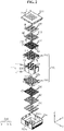
- FIG. 2 is a schematic partial exploded perspective view of the battery module according to an embodiment of the present disclosure.
- the battery module 200 may include a plurality of cylindrical battery cells 100, a module housing 210 and a cell frame 220.
- the cylindrical battery cell 100 may include a cylindrical battery can 120 and an electrode assembly (not shown) received in the battery can 120.
- the cylindrical battery cell 100 may include the battery can 120 standing upright in the vertical direction.
- the battery can 120 may include a material having high electrical conductivity, and for example, the battery can 120 may include an aluminum alloy or a copper alloy.
- 2 electrode terminals 111 may be formed on top and bottom of the battery can 120.
- a positive electrode terminal 111a may be formed on a flat circular upper surface on top of the battery can 120
- a negative electrode terminal 111b may be formed on a flat circular lower surface on bottom of the battery can 120.
- the battery can 120 may be coated with an electrical insulating element on the side.
- the battery can 120 since the battery can 120 is electrically connected to the electrode of the electrode assembly inside, the battery can 120 may be covered with an insulating film (not shown) or an electrical insulating adhesive on the side to prevent electrical leakage caused by the contact between an unintentional conductive object and the battery can 120.
- the electrode assembly may be formed by winding, into a jelly-roll shape, the positive electrode including a positive electrode plate coated with a positive electrode active material and the negative electrode including a negative electrode plate coated with a negative electrode active material with a separator interposed between the positive electrode and the negative electrode.
- the positive electrode may have a positive electrode tab attached thereto, and the positive electrode tab may be electrically connected to the positive electrode terminal 111a on top of the battery can 120.
- the negative electrode (not shown) may have a negative electrode tab attached thereto, and the negative electrode tab may be electrically connected to the negative electrode terminal 111b on bottom of the battery can 120.
- the plurality of cylindrical battery cells 100 may stand upright in the vertical direction and may be arranged in the horizontal direction within the module housing 210 when viewed from the direction F of FIG. 1 .
- the first battery module 200 includes 56 cylindrical battery cells 100.
- the 56 cylindrical battery cells 100 may stand upright in the vertical direction, and may be arranged closely to each other in the horizontal direction.
- the terms indicating directions as used herein such as front and rear, left, right, upper, lower may change depending on the position of an observe or the stated element.
- the front and rear, left, right, up and down directions are defined when viewed from the direction F.
- the plurality of battery cells 110 may stand upright in the vertical direction when received in the module housing 210.
- the module housing 210 may include an upper wall 211a, a side wall 213 and a lower wall 212a to form an internal space in which the plurality of cylindrical battery cells 100 is received.
- the side wall 213 of the module housing 210 include a front sidewall 213a, a rear sidewall 213b, a left sidewall 213c and a right sidewall 213d.
- the upper wall 211a may be mounted on top of the side wall 213 and they may be coupled to each other.
- the lower wall 212a may be mounted on bottom of the side wall 213 and they may be coupled to each other.
- the module housing 210 may include an upper housing 211 and a lower housing 212 coupled to the bottom of the upper housing 211.
- the upper housing 211 and the lower housing 212 may be bolt-coupled to each other.
- the module housing 210 may be configured to receive the cell frame 220 therein.
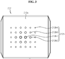
- FIG. 3 is a schematic bottom view of the battery module according to an embodiment of the present disclosure.
- At least one of the upper wall 211a or the lower wall 212a of the module housing 210 may have a plurality of cooling holes 211h through which a coolant K1 flows in and out.
- the upper wall 211a may have 30 cooling holes 211h that are open in the vertical direction.
- the lower wall 212a may have 30 cooling holes 212h that are open in the vertical direction.
- the coolant K1 may be continuously fed into the module housing 210 from the outside and the heated coolant K1 may be forced out of the module housing 210.
- a pump may be used to feed or force the coolant K1 out.
- the coolant K1 may be air, nitrogen, carbon dioxide, water, a Freon-based coolant, ammonia, acetone, methanol, ethanol, naphthalene, sulfur or mercury.
- At least two of the cooling holes 211h of the module housing 210 may have different sizes.
- the plurality of cooling holes 211h may be arranged in row and column, spaced a predetermined distance apart in the front-rear left-right directions.
- 2 or more of the cooling holes 211h arranged in rows may have different sizes.
- 2 or more of the cooling holes 211h arranged in columns may have different sizes.
- the battery module 200 of the present disclosure is configured such that at least two of the cooling holes 211h provided in the module housing 210 have different sizes, to increase the amount of the flow of coolant K1 at an area where cooling is required, thereby adjusting the temperature for each area within the battery module 200. Accordingly, it is possible to prevent overheat from occurring at a specific area of the battery module 200.
- the cell frame 220 may be received in the module housing 210.
- the cell frame 220 may include an insertion portion 225 having an inner wall around at least part of the outer surface of each of the plurality of cylindrical battery cells 100.
- the insertion portion 225 may have a hollow H4 around the outer side of the cylindrical battery cell 100.
- the insertion portion 225 may be configured to wrap around the outer surface of the upper and lower ends of the remaining cylindrical battery cells 100 except the electrode terminal.
- the cell frame 220 may include a plurality of cooling passages 221h configured to be in communication with the plurality of cooling holes 211h.
- the cooling passage 221h may be connected to the cooling hole 211h and may have a hollow tubular shape extending vertically, through which the coolant K1 flows.
- the cell frame 220 includes the plurality of cooling passages 221h configured to be in communication with the cooling holes 211h, to effectively transmit the heat of the coolant K1 flowing into the cooling hole 211h to the plurality of cylindrical battery cells 100 received in the insertion portions 225. Accordingly, with the module housing 210 and the cell frame 220, the present disclosure may protect the plurality of cylindrical battery cells 100 from external impacts, and supply the coolant K1 supplied from the outside to the plurality of cylindrical battery cells 100, thereby greatly increasing the cooling efficiency.
- At least two of the cooling holes 212h provided in the lower wall 212a of the lower housing 212 of the module housing 210 are configured such that the cooling hole 212h closer to the center has a larger diameter than the cooling hole 212h disposed at the outer side.
- 30 cooling holes 212h arranged in 6 rows x 5 columns provided in the lower wall 212a of the module housing 210 may be arranged in the front-rear and left-right direction.
- the cooling holes 212h1 of 3 rd row 3 rd column and 4 th row 3 rd column disposed at the center may be largest, the cooling holes 212h2 of 2 nd row 3 rd column, 3 rd row 2 nd column, 3 rd row 4 th column, 4 th row 2 nd column, 4 th row 4 th column and 5 th row 3 rd column may be second largest, the cooling holes 212h3 of 2 nd row 2 nd column, 2 nd row 4 th column, 3 rd row 1 st column, 3 rd row 5 th column, 4 th row 1 st column, 4 th row 5 th column, 5 th row 2 nd column and 5 th row 4 th column may be third largest, the cooling holes of 1 st row 2 nd column, 1 st row 3 rd column, 1 st row 4 th column, 2 nd row 1 st column, 2 nd row 5 th column, 5 th column,
- At least two of the cooling holes 212h provided in the lower wall 212a of the module housing 210 are configured such that the cooling hole 212h closer to the center has a larger diameter than the cooling hole 212h disposed at the outer side, so that the amount of the coolant K1 flowing into the lower wall 212a of the module housing 210 or the amount of the coolant K1 flowing out of the module housing 210 becomes larger as it is closer to the center of the module housing 210 in the horizontal direction.
- the battery module 200 of the present disclosure may have a higher cooling efficiency at the center in the horizontal direction. Accordingly, it is possible to effectively prevent the degradation of the cylindrical battery cell 100 caused by heat concentrated at the center of the plurality of cylindrical battery cells 100.
- the horizontal direction refers to a direction parallel to the ground when the module housing 210 is placed on the ground, and may be at least one direction on the plane perpendicular to the vertical direction.
- FIG. 4 is a schematic plane view of a battery module according to another embodiment of the present disclosure.
- an upper wall 211a of an upper housing 211A of a module housing may have cooling holes 211h, and at least two of the cooling holes 211h may be configured such that the cooling hole 211h close to the center has a larger diameter than the cooling hole 211h disposed at the outer side.
- cooling holes 211h arranged in 6 rows x 5 columns provided in the upper wall 211a of the module housing 210 may be arranged in the front-rear and left-right directions.
- the cooling holes 211h1 of 3 rd row 3 rd column and 4 th row 3 rd column disposed at the center may be largest
- the cooling holes 211h2 of 2 nd row 3 rd column, 3 rd row 2 nd column, 3 rd row 4 th column, 4 th row 2 nd column, 4 th row 4 th column and 5 th row 3 rd column may be second largest
- the cooling holes 211h3 of 2 nd row 2 nd column, 2 nd row 4 th column, 3 rd row 1 st column, 3 rd row 5 th column, 4 th row 1 st column, 4 th row 5 th column, 5 th row 2 nd column and 5 th row 4 th column may be third largest
- the cooling hole 211h closer to the center may have a larger diameter than the cooling hole 211h disposed at the outer side, so that the amount of the coolant K1 flowing into the upper wall 211a of the module housing 210 or the amount of the coolant K1 flowing out of the module housing 210 is larger as it is closer to the center of the module housing 210 in the horizontal direction.
- the battery module 200 may have a higher cooling efficiency at the center in the horizontal direction. Accordingly, it is possible to effectively prevent the degradation of the cylindrical battery cell 100 caused by heat concentrated at the center of the plurality of cylindrical battery cells 100.
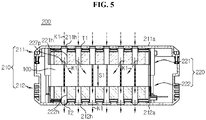
- FIG. 5 is a schematic cross-sectional view taken along the line A-A' of FIG. 1 .
- the cooling passage 221h may have the size corresponding to the diameter of the cooling hole 211h in communication with the cooling passage 221h.
- the cooling passage 221h disposed at the outermost side on the basis of the horizontal center may have the size corresponding to the diameter of the cooling hole 211h in communication with the cooling passage 221h.
- the size of the cooling passage 221h is set according to the diameter of the cooling hole 211h in communication with the cooling passage 221h, when at least two of the cooling holes 211h have different sizes, at least two of the cooling passages 221h may have different sizes.
- the cell frame 220 may include 30 cooling passages 221h arranged in 6 rows x 5 columns.
- the cooling passages 221h of 3 rd row 3 rd column and 4 th row 3 rd column disposed at the center may be largest
- the cooling passages 221h of 2 nd row 3 rd column, 3 rd row 2 nd column, 3 rd row 4 th column, 4 th row 2 nd column, 4 th row 4 th column, 5 th row 3 rd column may be second largest
- the cooling passages 221h of 2 nd row 2 nd column, 2 nd row 4 th column, 3 rd row 1 st column, 3 rd row 5 th column, 4 th row 1 st column, 4 th row 5 th column, 5 th row 2 nd column and 5 th row 4 th column may be third largest, the cooling passages 221h of 1 st row 2 nd column, 1 st row 3 rd column,
- the present disclosure is configured such that the cooling passage 221h has the size corresponding to the diameter of the cooling hole 211h in communication with the cooling passage 221h, to allow the coolant K1 flowing in through the cooling hole 211h of the module housing 210 to move along the cooling passage 221h without interruption, thereby increasing the cooling efficiency.
- At least two of the cooling passages 221h may have different sizes, to differently set the amount of the coolant K1 flowing in each of the cooling passages 221h. Accordingly, it is possible to intensively deliver the coolant K1 to an area in which more cooling is required within the battery module 200, thereby increasing the life of the battery module 200 and significantly reducing the probability that a failure will occur.
- the plurality of cylindrical battery cells 100 may be spaced apart from each other to allow the coolant K1 to flow.
- the cooling passage 221h may be disposed in the gap of the plurality of cylindrical battery cells 100.
- the plurality of cylindrical battery cells 100 may be spaced a predetermined distance apart from each other.
- the coolant K1 flowing in through the cooling hole may flow along the gap S1.
- the gap S1 may be in communication with the cooling passages 221h, 222h.
- the plurality of cylindrical battery cells 100 is spaced apart from each other to allow the coolant K1 to flow, resulting in a smooth flow of the coolant K1 in the gap S1. Accordingly, the coolant K1 may flow smoothly without delay, thereby increasing the cooling efficiency of the battery module 200.
- the cell frame 220 may include a lower case 222 and an upper case 221.
- the lower case 222 may be coupled to the bottom of the upper case 221.
- at least part of the upper surface of the lower case 222 may be connected to the lower surface of the upper case 221.
- the upper case 221 and the lower case 222 may be bolt-coupled to each other.
- part of the upper surface of the lower case 222 corresponding to the outer periphery may contact part of the lower surface of the upper case 221 corresponding to the outer periphery.
- the plurality of cooling passages 221h of the upper case 221 and the plurality of cooling passages 222h of the lower case 222 may be disposed at the corresponding positions in the vertical direction. That is, the coolant K1 flowing in through the cooling hole 211h of the module housing 210 may flow down along the cooling passage 221h of the upper case 221, then flow down through the cooling passage 222h of the lower case 222, and go to the outside.
- the cooling passages 221h may be disposed between the plurality of insertion portions 225 into which the cylindrical battery cells 100 are inserted.
- the plurality of cooling passages 221h of the upper case 221 and the plurality of cooling passages 222h of the lower case 222 may be spaced apart from each other in the vertical direction. That is, parts of the upper case 221 and the lower case 222 may be hollow (empty). For example, the remaining lower surface except the outer periphery of the upper case 221 in contact with the lower case 222 may be recessed in the upward direction. The remaining upper surface except the outer periphery of the lower case 222 in contact with the upper case 221 may be recessed in the downward direction.
- the 30 cooling passages 221h of the upper case 221 and the 30 cooling passages 222h of the lower case 222 may be spaced a predetermined distance apart from each other in the vertical direction.
- Each of the upper case 221 and the lower case 222 may have a step structure.
- the hollow (empty) space formed by the upper case 221 and the lower case 222 may be configured to allow the coolant K1 flowing in through the cooling passage 221h of the cell frame 220 to freely move along many directions in a distributed manner within the hollow (empty) space.
- the present disclosure has the hollow (empty) space between the upper case 221 and the lower case 222 since the plurality of cooling passages 221h of the upper case 221 and the plurality of cooling passages 222h of the lower case 222 are spaced apart from each other in the vertical direction.
- the coolant K1 may intensively flow in an area in which more cooling is required (for example, the horizontal center of the plurality of cylindrical battery cells) within the module housing 210. Accordingly, it is possible to increase the life of the battery module 200, and significantly reduce a failure rate.
- the plurality of cooling holes 211h provided in the upper wall 211a of the module housing 210 may be configured to introduce the coolant K1 into the module housing 210 from the outside by an external device capable of feeding the coolant K1.
- the plurality of cooling holes 212h provided in the lower wall 212a of the module housing 210 may be configured to force the coolant K1 out of the module housing 210 by an external device capable of sucking the coolant K1.
- an external device capable of sucking the coolant K1 it is possible to reduce the influence of heat from a pump or a motor provided in the external device on the temperature rise of the coolant K1 more fundamentally.
- the plurality of cooling holes 212h provided in the lower wall 212a of the module housing 210 is configured to force the coolant K1 fed into the module housing 210 out by the external device capable of sucking the coolant K1, it is possible to prevent the coolant K1 from increasing the temperature by the external device. Accordingly, it is possible to cool the battery module 200 more effectively.
- the cell frame 220 when the cell frame 220 according to an embodiment of the present disclosure is configured to allow the coolant K1 fed from the outside to move along the cooling passage 221h provided in the upper case 221, at least some of the cooling passages 221h of the upper case 221 may include a guide portion configured to change the flow direction of the coolant K1 to the horizontal inward direction of the plurality of cylindrical battery cells 100.
- the guide portion may include a guide protrusion 227p extending in the horizontal inward direction of the plurality of cylindrical battery cells 100.
- the cooling passage 221h disposed at the outer side on the basis of the horizontal center may have the guide protrusion 227p.
- the guide protrusion 227p may be configured to always move the coolant K1 fed into the cooling passage 221h of the upper case 221 to the center of the plurality of cylindrical battery cells 100 through the gap S1 when the coolant K1 flows out of the cooling passage 221h. Accordingly, the guide protrusions 227p provided in the plurality of cooling passages 221h may extend toward the center of the plurality of cylindrical battery cells 100.
- the plurality of guide protrusions 227p may extend to different extents or at different angles.
- the guide protrusion 227p disposed at the outer side on the basis of the horizontal center may extend to a greater extent or at a higher angle.
- the guide protrusion 227p provided in the cooling passage 221h closer to the horizontal center may extend to a smaller extent or at a lower angle than the guide protrusion 227p disposed at the outer side.
- the cooling passage 221h disposed at the horizontal center may not have the guide protrusion 227p.
- the guide portion includes the guide protrusions 227p extending in the horizontal inward direction of the plurality of cylindrical battery cells 100, to induce the coolant K1 to intensively flow at the center of the plurality of cylindrical battery cells 100. Accordingly, it is possible to prevent some battery cells from degrading due to heat imbalance of the plurality of cylindrical battery cells 100, thereby significantly increasing the life of the battery module 200.
- FIG. 6 is a schematic vertical cross-sectional view of the battery module according to another embodiment of the present disclosure.
- the guide portion of the battery module 200A may have a bent structure 227k in which the cooling passages 221h of the upper case 221 are bent in the horizontal inward direction of the plurality of cylindrical battery cells 100. That is, the present disclosure may have the bent structure 227k formed by bending parts of the cooling passages 221h, to guide the coolant K1 discharged to the gap S1 through the cooling passages 221h to move toward the horizontal center of the plurality of cylindrical battery cells 100.
- the guide portion disposed at the outer side on the basis of the horizontal center may have a higher bend angle of the cooling passage 221h.
- the bend angle of the cooling passage 221h closer to the horizontal center may be smaller than the guide portion disposed at the outer side.
- the cooling passage 221h disposed at the horizontal center may not have the bent guide portion.
- the cooling passage 221h of the upper case 221 includes the guide portion bent in the horizontal inward direction of the plurality of cylindrical battery cells 100, to induce the coolant K1 to intensively flow at the center of the plurality of cylindrical battery cells 100. Accordingly, it is possible to prevent some battery cells from degrading due to heat imbalance of the plurality of cylindrical battery cells 100, thereby significantly increasing the life of the battery module 200.
- the plurality of cooling holes 211h provided in the upper wall 211a of the module housing 210 may include a tapered structure T1 having the inner diameter gradually decreasing in the vertical inward direction toward the plurality of cylindrical battery cells 100.
- each of 30 cooling holes 211h provided in the upper wall 211a of the module housing 210 may include the tapered structure T1 having the inner diameter gradually decreasing in the downward direction toward the plurality of cylindrical battery cells 100.
- the plurality of cooling holes 211h may have the tapered structure T1 to allow the coolant K1 to flow into the module housing 210 in a large amount at a higher flow rate.
- the plurality of cooling holes 211h provided in the upper wall 211a of the module housing 210 includes the tapered structure T1 having the inner diameter gradually decreasing in the vertical inward direction toward the plurality of cylindrical battery cells 100, to increase the rate and amount of the coolant K1 flowing into the module housing 210, thereby increasing the cooling efficiency of the battery module 200.
- the plurality of cooling holes 212h provided in the lower wall 212a of the module housing 210 may include a tapered structure T2 having the inner diameter gradually decreasing in the vertical outward direction (to the outside).
- each of 30 cooling holes 211h provided in the lower wall 212a of the module housing 210 may include the tapered structure T2 having the inner diameter gradually decreasing in the downward direction to force the coolant K1 out.
- the plurality of cooling holes 212h provided in the lower wall 212a of the module housing 210 may have the tapered structure T2 to allow the coolant K1 heated in the module housing 210 to flow out of the module housing 210 in a large amount at a higher flow rate.
- the plurality of cooling holes 212h provided in the lower wall 212a of the module housing 210 includes the tapered structure T2 having the inner diameter gradually decreasing in the vertical outward direction, to increase the rate and amount of the coolant K1 flowing out of the module housing 210, thereby further increasing the cooling efficiency of the battery module 200.
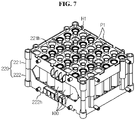
- FIG. 7 is a schematic perspective view of some components of the battery pack according to an embodiment of the present disclosure.
- the cooling passage 221h provided in the cell frame 220 may have an outer end extending vertically from the outer side of the cell frame 220.
- the cooling passage 221h provided in the upper case 221 may extend further upwards than the outer side around the cooling passage 221h.
- the cooling passage 222h provided in the lower case 222 may extend further downwards than the outer side around the cooling passage 222h.
- the cell frame 220 may have an exposure hole H1 through which the electrode terminal (111 in FIG. 2 ) is exposed to the outside.
- the electrode terminal 111 in FIG. 2
- 42 cylindrical battery cells 100 may be inserted and received in 42 insertion portions 225 of the cell frame 220.
- the electrode terminals of the 42 cylindrical battery cells 100 may be exposed to the outside through the exposure holes H1 of the cell frame 220.
- Each of the upper case 221 and the lower case 222 may have 42 exposure holes H1.
- the battery module 200 may further include a plurality of connecting plates 230 mounted on each of the top and bottom of the cell frame 220.
- each of the plurality of connecting plates 230 may include a connection hole H2 in communication with the exposure hole HI, a connection terminal 232 extending from the inner side of the connection hole H2 to electrically connect the plurality of cylindrical battery cells 100, and an insertion groove H3 into which the end of the cooling passage 221h is inserted.
- the connecting plate 230 may include an electrically conductive material.
- the electrically conductive material may be a metal alloy including copper, nickel, aluminum, gold and silver as the main material.
- the upper case 221 may include 30 cooling passages 221h extending further upwards than the remaining upper surface.
- the connecting plate 230 mounted on the upper surface of the upper case 221 may have 30 insertion grooves H3 into which the ends of 30 cooling passages 221h are inserted.
- the lower case 222 may include 30 cooling passages (not shown) extending further downwards than the remaining lower surface.
- the connecting plate 230 mounted on the lower surface of the lower case 222 may have 30 insertion grooves H3 into which the ends of the 30 cooling passages (not shown) are inserted.
- the battery module 200 of the present disclosure further includes at least one connecting plate 230 having the insertion groove H3 into which the end of the cooling passage 221h is inserted, the connecting plate 230 electrically connected to the electrode terminal may generate a very large amount of heat due to electrical resistance, and thus when the end of the cooling passage 221h is inserted into the insertion groove H3 of the connecting plate 230, the heat of the connecting plate 230 may be effectively cooled down through the cooling passage 221h through which the coolant K1 flows.
- the present disclosure may effectively prevent the connecting plate 230 from moving through the insertion groove H3 through which the cooling passage 221h is inserted during the welding operation between the connection terminal 232 and the electrode terminal (111 in FIG. 2 ), thereby greatly increasing the efficiency of the welding operation.
- a partition wall PI may be provided on each of the upper surface and the lower surface of the cell frame 220.
- the partition wall PI may extend in the outward direction and extend linearly in the horizontal direction.
- Part of the partition wall PI may be configured to connect the plurality of cooling passages 221h.
- the partition wall PI linearly extending in the front-rear and left-right directions may be provided on the upper surface of the cell frame 220.
- the partition wall PI may extend along the outer periphery of the upper surface of the cell frame 220.
- the partition wall PI may be disposed between the plurality of cooling passages 221h.
- the connecting plate 230 may be mounted in the space defined by the partition wall PI on the upper and lower surfaces of the cell frame 220.
- the upper surface of the upper case 221 may be divided into 7 areas by the partition wall P1.
- 7 connecting plates 230 may be respectively mounted on the 7 areas.
- the partition wall PI extending in the outward direction and extending linearly in the horizontal direction and having part connecting the plurality of cooling passages 221h is provided on each of the upper and lower surfaces of the cell frame 220, and thus when at least two connecting plates 230 are mounted on the upper and lower surfaces of the cell frame 220, it is possible to electrically insulate the at least two connecting plates 230 to prevent a short circuit between the at least two connecting plates 230. Accordingly, it is possible to effectively increase the safety and durability of the battery module 200 of the present disclosure.
- the partition wall PI may be provided on the outer periphery of each of the upper surface and the lower surface of the cell frame 220. Part of the partition wall PI formed on the periphery may have an opening that runs in the horizontal direction. Part of the connecting plate 230 may extend to the outside through the opening. The partition wall PI provided on the periphery may prevent the separation of the connecting plate 230 or the contact with an external conductive material.
- the battery module 200 may further include a thermally conductive pad 240 and a heat sink 250.
- the thermally conductive pad 240 may include a material having high thermal conductivity.
- the thermally conductive pad 240 may include an electrical insulating material.
- the thermally conductive pad 240 may have a solidified form of polymer resin having high thermal conductivity or a silicon-based resin.
- the polymer resin may be polysiloxane resin, polyamide resin, urethane resin or epoxy-based resin.
- the thermally conductive pad 240 may be a solidified form of an added adhesive material.
- the adhesive material may be an acrylic, polyester-based, polyurethane-based or rubber-based material.
- the thermally conductive pad 240 may have a fixing groove H5 mounted on the outer side of the connecting plate 230, into which the cooling passage 221h is inserted.
- the thermally conductive pad 240 mounted on top of the upper case 221 may have 30 fixing grooves H5 into which the ends of the 30 cooling passages 221h are inserted.
- the thermally conductive pad 240 of the present disclosure includes the fixing grooves H5 into which the cooling passages 221h are inserted, so it is easy to mount and fix the thermally conductive pad 240 onto the cell frame 220, thereby increasing the fabrication efficiency.
- the thermally conductive pad 240 may effectively absorb heat of the connecting plate 230 that generates a very large amount of heat due to electrical resistance, thereby effectively increasing the cooling efficiency of the battery module 200.
- the heat sink 250 may have a fixing hole H6 mounted on the outer side of the thermally conductive pad 240, into which the cooling passage 221h is inserted.
- the heat sink 250 may be configured to be disposed between the module housing 210 and the thermally conductive pad 240.
- the heat sink 250 may be a cooling plate including a material having high thermal conductivity.
- the material having high thermal conductivity may be copper or aluminum.
- a battery pack (not shown) according to the present disclosure may include at least one battery module 200.
- the battery pack according to the present disclosure may further include a pack case to receive the battery module 200, various types of devices to control the charge/discharge of the battery module 200, for example, a Battery Management System (BMS), a current sensor and a fuse.
- BMS Battery Management System
- An electronic device may include the battery pack.
- the electronic device (not shown) may include a case (not shown) to receive the battery pack therein.
- a vehicle (not shown) according to the present disclosure may include the battery pack.
- the vehicle may be, for example, an electric vehicle including an electric motor (not shown) using the battery pack as a power source.
- Battery module 100 Cylindrical battery cell
- 210 Module housing 211, 212: Upper housing, Lower housing 220: Cell frame 211h, 212h: Cooling hole 221h, 222h: Cooling passage 221: Insertion portion 221, 222: Upper case, Lower case K1: Coolant 227p: Guide protrusion 227k: Bent structure T1, T2: Tapered structure 230: Connecting plate H1, H2, H3: Exposure hole, Connection hole, Insertion groove 232: Connection terminal P1: Partition wall 240: Thermally conductive pad 250: Heat sink
- the present disclosure relates to a battery module and a battery pack.
- the present disclosure can be used in the industry of battery modules, and electronic devices comprising battery packs.
Abstract
Disclosed is a battery module having the increased operating life by efficiently maintaining the heat balance. To achieve the object, the battery module according to the present disclosure includes a plurality of cylindrical battery cells including an electrode terminal formed in each of an upper end and a lower end, and arranged in a horizontal direction, a module housing including an upper wall, a sidewall and a lower wall to receive the plurality of cylindrical battery cells, at least one of the upper wall or the lower wall having a plurality of cooling holes through the coolant flows in and out, at least two of the cooling holes having different sizes, and a cell frame including an insertion portion having an inner wall to wrap around at least part of an outer surface of each of the plurality of cylindrical battery cells, and a plurality of cooling passages connected to the cooling holes in communication with the cooling holes and having a tubular shape extending in a vertical direction to allow the coolant to flow in and out.
Description
- The present disclosure relates to a battery module comprising a cell frame, and more particularly, to a battery module having the increased operating life by efficiently maintaining the heat balance.
- The present application claims the benefit of
Korean Patent Application No. 10-2019-0105126 filed on August 27, 2019 - Currently, commercially available secondary batteries include nickel cadmium batteries, nickel hydride batteries, nickel zinc batteries, lithium secondary batteries, etc., and among them, lithium secondary batteries have little or no memory effect, and thus they are gaining more attention than nickel-based secondary batteries for their advantages that recharging can be done whenever it is convenient, the self-discharge rate is very low and the energy density is high.
- The lithium secondary battery mainly uses lithium-based oxide and a carbon material for a positive electrode active material and a negative electrode active material respectively. The lithium secondary battery includes an electrode assembly including a positive electrode plate coated with the positive electrode active material, a negative electrode plate coated with the negative electrode active material and a separator interposed between, and a hermetically sealed packaging material or battery pouch case in which the electrode assembly is received together with an electrolyte solution.
- More recently, secondary batteries are being widely used in not only small devices such as portable electronic products but also medium- and large-scale devices such as vehicles and energy storage systems (ESSs). For use in medium- and large-scale devices, many secondary batteries are electrically connected to increase the capacity and output. In particular, pouch-type secondary batteries are widely used in medium- and large-scale devices because they are easy to stack.
- With the growing need for a large-capacity structure for use as an energy storage source, there is an increasing demand for a battery module including a plurality of secondary batteries electrically connected in series and/or in parallel and a metal plate electrically connecting the secondary batteries.
- The battery module generally uses cooling technology to prevent the rapid temperature rise of the secondary batteries during use. For example, it is general to cool the received secondary batteries by feeding cold air into a housing of the battery module.
- However, since the contact area with cold air in the battery module is not uniform for each secondary battery, the cooling effect concentrates on some secondary batteries and the cooling effect on the remaining secondary batteries is low, so overheat may occur in some secondary batteries. That is, in case that heat imbalance occurs, when some of secondary batteries are placed in high temperature condition, degradation occurs, and the life of some secondary batteries may greatly reduce, which may be the main factor that reduces the life of the battery module.
- Accordingly, to increase the life of the battery module, it is important to maintain the heat balance (uniform temperature) between the secondary batteries during the use of the battery module.
- The present disclosure is designed to solve the above-described problem, and therefore the present disclosure is directed to providing a battery module having the increased operational life by efficiently maintaining the heat balance.
- These and other objects and advantages of the present disclosure can be understood by the following description, and will be apparent from the embodiments of the present disclosure. In addition, it will be readily appreciated that the objects and advantages of the present disclosure can be realized by means and combinations thereof.
- To achieve the above-described object, a battery module according to the present disclosure includes a plurality of cylindrical battery cells including an electrode terminal formed in each of an upper end and a lower end, and arranged in a horizontal direction, a module housing including an upper wall, a sidewall and a lower wall to receive the plurality of cylindrical battery cells, at least one of the upper wall or the lower wall having a plurality of cooling holes through the coolant flows in and out, at least two of the cooling holes having different sizes, and a cell frame received in the module housing and including an insertion portion having an inner wall to wrap around at least part of an outer surface of each of the plurality of cylindrical battery cells, and a plurality of cooling passages connected to the cooling holes in communication with the cooling holes and having a tubular shape extending in a vertical direction to allow the coolant to flow in and out.
- Additionally, at least two of the plurality of cooling holes may be configured such that a cooling hole closer to a center has a larger diameter than a cooling hole disposed at an outer side.
- Additionally, the cooling passage may have a size corresponding to a diameter of the cooling hole in communication with the cooling passage.
- Additionally, the plurality of cylindrical battery cells may be spaced apart from each other to allow the coolant to flow.
- Additionally, the cell frame may include an upper case including the plurality of insertion portions and the plurality of cooling passages, and a lower case coupled to bottom of the upper case and including the plurality of insertion portions and the plurality of cooling passages.
- Additionally, the plurality of cooling passages of the upper case and the plurality of cooling passages of the lower case may be disposed corresponding to each other in the vertical direction, and the plurality of cooling passages of the upper case and the plurality of cooling passages of the lower case may be spaced apart from each other in the vertical direction.
- Additionally, the plurality of cooling holes in the upper wall of the module housing may be configured to allow the coolant to flow from outside to inside, and the plurality of cooling holes provided in the lower wall of the module housing may be configured to force the coolant fed into the module housing out.
- Additionally, at least some of the cooling passages of the upper case may include a guide portion configured to change a flow direction of the coolant to a horizontal inward direction of the plurality of cylindrical battery cells.
- Additionally, the guide portion may include a guide protrusion extending in the horizontal inward direction of the plurality of cylindrical battery cells.
- Additionally, the guide portion may have a bent structure in which the cooling passages of the upper case are bent in the horizontal inward direction of the plurality of cylindrical battery cells.
- Additionally, the plurality of cooling holes provided in the upper wall of the module housing may include a tapered structure having an inner diameter gradually decreasing in the horizontal inward direction.
- Additionally, the plurality of cooling holes provided in the lower wall of the module housing may include a tapered structure having an inner diameter gradually decreasing in a vertical outward direction.
- Additionally, the cooling passage may have an outer end extending in the vertical direction from an outer surface of the cell frame, and the cell frame may have an exposure hole to expose the electrode terminal to the outside.
- Additionally, the battery module may further include a connection hole mounted on each of the upper and lower parts of the cell frame, the connection hole in communication with the exposure hole, a connection terminal extending from an inner side of the connection hole to electrically connect the plurality of cylindrical battery cells, and at least one connecting plate having an insertion groove in which the end of the cooling passage is inserted.
- Additionally, each of an upper surface and a lower surface of the cell frame may have a partition wall extending in an outward direction and extending linearly in the horizontal direction, of which part connects the plurality of cooling passages, and the partition wall may be disposed corresponding to an outer periphery of the connecting plate in the horizontal direction.
- Additionally, the battery module may further include a thermally conductive pad mounted on an outer side of the connecting plate and including a fixing groove into which the cooling passage is inserted, and a heat sink the mounted on an outer side of the thermally conductive pad and including a fixing hole into which the cooling passage is inserted.
- Additionally, to achieve the above-described object, a battery pack according to the present disclosure includes at least one battery module.
- Additionally, to achieve the above-described object, an electronic device according to the present disclosure includes the battery pack.
- According to an aspect of the present disclosure, the battery module of the present disclosure is configured such that at least two of the plurality of cooling holes provided in the module housing have different sizes, to increase the amount of the flow of coolant in an area where cooling is required, thereby adjusting the temperature for each area inside the battery module. Accordingly, it is possible to prevent overheat at a specific area of the battery module.
- The cell frame of the present disclosure includes the plurality of cooling passages configured to be in communication with the cooling holes, heat of the coolant flowing into the cooling holes may be effectively transmitted to the plurality of cylindrical battery cells received in the insertion portion. The present disclosure may protect the plurality of cylindrical battery cells from external impacts by the module housing and the cell frame, and supply the coolant supplied from the outside to the plurality of cylindrical battery cells, thereby greatly increasing the cooling efficiency.
- According to an aspect of an embodiment of the present disclosure, the present disclosure is configured such that among at least two of the plurality of cooling holes provided in the lower wall of the module housing, the cooling hole closer to the center has a larger diameter than the cooling hole disposed at the outer side, so that a larger amount of coolant may be fed into the lower wall of the module housing or a larger amount of coolants fed into the module housing may be forced out as it is closer to the horizontal center of the module housing.
- According to an aspect of the present disclosure, at least two of the plurality of cooling holes provided in the upper wall of the module housing are configured such that the cooling hole closer to the center has a larger diameter than the cooling hole disposed at the outer side, so that a larger amount of coolants may be fed into the upper wall of the module housing or a larger amount of coolants fed into the module housing may be forced out as it is closer to the horizontal center of the module housing.
- According to an aspect of the present disclosure, the cooling passage is configured to have the size corresponding to the dimeter of the cooling hole in communication with the cooling passage, to allow the coolant flowing in through the cooling hole of the module housing to move along the cooling passage without interruption, thereby increasing the cooling efficiency.
- According to an aspect of the present disclosure, the plurality of cylindrical battery cells may be spaced apart from each other to allow the coolant to flow, and thus the present disclosure may allow the coolant to flow in the gap well. Accordingly, there is no stagnant coolant, thereby increasing the cooling efficiency of the battery module.
- According to an aspect of the present disclosure, the present disclosure is configured such that the plurality of cooling passages of the upper case and the plurality of cooling passages of the lower case are spaced apart from each other in the vertical direction, to form a hollow (empty) space between the upper case and the lower case, thereby allowing the coolant to intensively flow in an area in which more cooling is required (for example, at the horizontal center of the plurality of cylindrical battery cells) inside the module housing through which the gap. Accordingly, it is possible to increase the life of the battery module, and significantly reduce a failure rate.
- The accompanying drawings illustrate preferred embodiments of the present disclosure, and together with the foregoing disclosure, serve to provide further understanding of the technical spirit of the present disclosure. However, the present disclosure is not to be construed as being limited to the drawings.
-
FIG. 1 is a schematic perspective view of a battery module according to an embodiment of the present disclosure. -
FIG. 2 is a schematic exploded perspective view of a battery module according to an embodiment of the present disclosure. -
FIG. 3 is a schematic bottom view of a battery module according to an embodiment of the present disclosure. -
FIG. 4 is a schematic plane view of a battery module according to another embodiment of the present disclosure. -
FIG. 5 is a schematic cross-sectional view taken along the line A-A' ofFIG. 1 . -
FIG. 6 is a schematic vertical cross-sectional view of a battery module according to another embodiment of the present disclosure. -
FIG. 7 is a schematic partial perspective view of a battery pack according to an embodiment of the present disclosure. - Hereinafter, the preferred embodiments of the present disclosure will be described in detail with reference to the accompanying drawings. Prior to the description, it should be understood that the terms or words used in the specification and the appended claims should not be construed as being limited to general and dictionary meanings, but rather interpreted based on the meanings and concepts corresponding to the technical aspects of the present disclosure on the basis of the principle that the inventor is allowed to define the terms appropriately for the best explanation.
- Therefore, the embodiments described herein and illustrations shown in the drawings are just a most preferred embodiment of the present disclosure, but not intended to fully describe the technical aspects of the present disclosure, so it should be understood that a variety of other equivalents and modifications could have been made thereto at the time that the application was filed.
-
FIG. 1 is a schematic perspective view of a battery module according to an embodiment of the present disclosure.FIG. 2 is a schematic partial exploded perspective view of the battery module according to an embodiment of the present disclosure. - Referring to
FIGS. 1 and2 , thebattery module 200 according to an embodiment of the present disclosure may include a plurality ofcylindrical battery cells 100, amodule housing 210 and acell frame 220. - Here, the
cylindrical battery cell 100 may include a cylindrical battery can 120 and an electrode assembly (not shown) received in the battery can 120. - The
cylindrical battery cell 100 may include the battery can 120 standing upright in the vertical direction. The battery can 120 may include a material having high electrical conductivity, and for example, the battery can 120 may include an aluminum alloy or a copper alloy. - 2
electrode terminals 111 may be formed on top and bottom of the battery can 120. In detail, apositive electrode terminal 111a may be formed on a flat circular upper surface on top of the battery can 120, and anegative electrode terminal 111b may be formed on a flat circular lower surface on bottom of the battery can 120. - The battery can 120 may be coated with an electrical insulating element on the side.
- That is, since the battery can 120 is electrically connected to the electrode of the electrode assembly inside, the battery can 120 may be covered with an insulating film (not shown) or an electrical insulating adhesive on the side to prevent electrical leakage caused by the contact between an unintentional conductive object and the battery can 120.
- The electrode assembly (not shown) may be formed by winding, into a jelly-roll shape, the positive electrode including a positive electrode plate coated with a positive electrode active material and the negative electrode including a negative electrode plate coated with a negative electrode active material with a separator interposed between the positive electrode and the negative electrode. The positive electrode (not shown) may have a positive electrode tab attached thereto, and the positive electrode tab may be electrically connected to the
positive electrode terminal 111a on top of the battery can 120. The negative electrode (not shown) may have a negative electrode tab attached thereto, and the negative electrode tab may be electrically connected to thenegative electrode terminal 111b on bottom of the battery can 120. - The plurality of
cylindrical battery cells 100 may stand upright in the vertical direction and may be arranged in the horizontal direction within themodule housing 210 when viewed from the direction F ofFIG. 1 . - For example, as shown in
FIG. 3 , thefirst battery module 200 includes 56cylindrical battery cells 100. The 56cylindrical battery cells 100 may stand upright in the vertical direction, and may be arranged closely to each other in the horizontal direction. - Here, the terms indicating directions as used herein such as front and rear, left, right, upper, lower may change depending on the position of an observe or the stated element. However, for convenience of description, the front and rear, left, right, up and down directions are defined when viewed from the direction F.
- The plurality of battery cells 110 may stand upright in the vertical direction when received in the
module housing 210. - Referring back to
FIGS. 1 and2 , themodule housing 210 may include anupper wall 211a, aside wall 213 and alower wall 212a to form an internal space in which the plurality ofcylindrical battery cells 100 is received. For example, as shown inFIG. 1 , theside wall 213 of themodule housing 210 include afront sidewall 213a, arear sidewall 213b, aleft sidewall 213c and aright sidewall 213d. Theupper wall 211a may be mounted on top of theside wall 213 and they may be coupled to each other. Thelower wall 212a may be mounted on bottom of theside wall 213 and they may be coupled to each other. - The
module housing 210 may include anupper housing 211 and alower housing 212 coupled to the bottom of theupper housing 211. Theupper housing 211 and thelower housing 212 may be bolt-coupled to each other. Themodule housing 210 may be configured to receive thecell frame 220 therein. -
FIG. 3 is a schematic bottom view of the battery module according to an embodiment of the present disclosure. - Referring to
FIG. 3 together withFIG. 2 , at least one of theupper wall 211a or thelower wall 212a of themodule housing 210 may have a plurality ofcooling holes 211h through which a coolant K1 flows in and out. For example, as shown inFIG. 2 , theupper wall 211a may have 30cooling holes 211h that are open in the vertical direction. Thelower wall 212a may have 30cooling holes 212h that are open in the vertical direction. - Here, the coolant K1 may be continuously fed into the
module housing 210 from the outside and the heated coolant K1 may be forced out of themodule housing 210. A pump may be used to feed or force the coolant K1 out. - For example, the coolant K1 may be air, nitrogen, carbon dioxide, water, a Freon-based coolant, ammonia, acetone, methanol, ethanol, naphthalene, sulfur or mercury.
- At least two of the
cooling holes 211h of themodule housing 210 may have different sizes. When viewed from the direction F ofFIG. 1 , the plurality ofcooling holes 211h may be arranged in row and column, spaced a predetermined distance apart in the front-rear left-right directions. In this instance, 2 or more of thecooling holes 211h arranged in rows may have different sizes. 2 or more of thecooling holes 211h arranged in columns may have different sizes. - According to this configuration of the present disclosure, the
battery module 200 of the present disclosure is configured such that at least two of thecooling holes 211h provided in themodule housing 210 have different sizes, to increase the amount of the flow of coolant K1 at an area where cooling is required, thereby adjusting the temperature for each area within thebattery module 200. Accordingly, it is possible to prevent overheat from occurring at a specific area of thebattery module 200. - Referring back to
FIGS. 1 and2 , thecell frame 220 may be received in themodule housing 210. - The
cell frame 220 may include aninsertion portion 225 having an inner wall around at least part of the outer surface of each of the plurality ofcylindrical battery cells 100. Theinsertion portion 225 may have a hollow H4 around the outer side of thecylindrical battery cell 100. For example, theinsertion portion 225 may be configured to wrap around the outer surface of the upper and lower ends of the remainingcylindrical battery cells 100 except the electrode terminal. - The
cell frame 220 may include a plurality ofcooling passages 221h configured to be in communication with the plurality ofcooling holes 211h. Thecooling passage 221h may be connected to thecooling hole 211h and may have a hollow tubular shape extending vertically, through which the coolant K1 flows. - According to this configuration of the present disclosure, the
cell frame 220 includes the plurality ofcooling passages 221h configured to be in communication with thecooling holes 211h, to effectively transmit the heat of the coolant K1 flowing into thecooling hole 211h to the plurality ofcylindrical battery cells 100 received in theinsertion portions 225. Accordingly, with themodule housing 210 and thecell frame 220, the present disclosure may protect the plurality ofcylindrical battery cells 100 from external impacts, and supply the coolant K1 supplied from the outside to the plurality ofcylindrical battery cells 100, thereby greatly increasing the cooling efficiency. - Referring back to
FIG. 3 , at least two of thecooling holes 212h provided in thelower wall 212a of thelower housing 212 of themodule housing 210 are configured such that thecooling hole 212h closer to the center has a larger diameter than thecooling hole 212h disposed at the outer side. For example, as shown inFIG. 3 , 30cooling holes 212h arranged in 6 rows x 5 columns provided in thelower wall 212a of themodule housing 210 may be arranged in the front-rear and left-right direction. Among them, the cooling holes 212h1 of 3rd row 3rd column and 4th row 3rd column disposed at the center may be largest, the cooling holes 212h2 of 2nd row 3rd column, 3rd row 2nd column, 3rd row 4th column, 4th row 2nd column, 4th row 4th column and 5th row 3rd column may be second largest, the cooling holes 212h3 of 2nd row 2nd column, 2nd row 4th column, 3rd row 1st column, 3rd row 5th column, 4th row 1st column, 4th row 5th column, 5th row 2nd column and 5th row 4th column may be third largest, the cooling holes of 1st row 2nd column, 1st row 3rd column, 1st row 4th column, 2nd row 1st column, 2nd row 5th column, 5th row 1st column, 5th row 5th column, 6th row 2nd column, 6th row 3rd column, 6th row 4th column may be fourth largest, and the cooling holes 212h4 of 1st row 1st column, 1st row 5th column, 6th row 1st column and 6th row 5th column may be fifth largest. - According to this configuration of the present disclosure, at least two of the
cooling holes 212h provided in thelower wall 212a of themodule housing 210 are configured such that thecooling hole 212h closer to the center has a larger diameter than thecooling hole 212h disposed at the outer side, so that the amount of the coolant K1 flowing into thelower wall 212a of themodule housing 210 or the amount of the coolant K1 flowing out of themodule housing 210 becomes larger as it is closer to the center of themodule housing 210 in the horizontal direction. - That is, the
battery module 200 of the present disclosure may have a higher cooling efficiency at the center in the horizontal direction. Accordingly, it is possible to effectively prevent the degradation of thecylindrical battery cell 100 caused by heat concentrated at the center of the plurality ofcylindrical battery cells 100. - Here, the horizontal direction refers to a direction parallel to the ground when the
module housing 210 is placed on the ground, and may be at least one direction on the plane perpendicular to the vertical direction. -
FIG. 4 is a schematic plane view of a battery module according to another embodiment of the present disclosure. - Referring to
FIG. 4 together withFIG. 2 , anupper wall 211a of anupper housing 211A of a module housing according to another embodiment of the present disclosure may havecooling holes 211h, and at least two of thecooling holes 211h may be configured such that thecooling hole 211h close to the center has a larger diameter than thecooling hole 211h disposed at the outer side. - For example, as shown in
FIG. 4 , 30cooling holes 211h arranged in 6 rows x 5 columns provided in theupper wall 211a of themodule housing 210 may be arranged in the front-rear and left-right directions. Among them, the cooling holes 211h1 of 3rd row 3rd column and 4th row 3rd column disposed at the center may be largest, the cooling holes 211h2 of 2nd row 3rd column, 3rd row 2nd column, 3rd row 4th column, 4th row 2nd column, 4th row 4th column and 5th row 3rd column may be second largest, the cooling holes 211h3 of 2nd row 2nd column, 2nd row 4th column, 3rd row 1st column, 3rd row 5th column, 4th row 1st column, 4th row 5th column, 5th row 2nd column and 5th row 4th column may be third largest, thecooling holes 211h of 1st row 2nd column, 1st row 3rd column, 1st row 4th column, 2nd row 1st column, 2nd row 5th column, 5th row 1st column, 5th row 5th column, 6th row 2nd column, 6th row 3rd column and 6th row 4th column may be fourth largest, and the cooling holes 211h4 of 1st row 1st column, 1st row 5th column, 6th row 1st column and 6th row 5th column may be fifth largest. - According to this configuration of the present disclosure, among at least two of the
cooling holes 211h provided in theupper wall 211a of theupper housing 211A, thecooling hole 211h closer to the center may have a larger diameter than thecooling hole 211h disposed at the outer side, so that the amount of the coolant K1 flowing into theupper wall 211a of themodule housing 210 or the amount of the coolant K1 flowing out of themodule housing 210 is larger as it is closer to the center of themodule housing 210 in the horizontal direction. - That is, the
battery module 200 may have a higher cooling efficiency at the center in the horizontal direction. Accordingly, it is possible to effectively prevent the degradation of thecylindrical battery cell 100 caused by heat concentrated at the center of the plurality ofcylindrical battery cells 100. -
FIG. 5 is a schematic cross-sectional view taken along the line A-A' ofFIG. 1 . - Referring to
FIG. 5 together withFIG. 2 , thecooling passage 221h may have the size corresponding to the diameter of thecooling hole 211h in communication with thecooling passage 221h. As shown inFIG. 5 , thecooling passage 221h disposed at the outermost side on the basis of the horizontal center may have the size corresponding to the diameter of thecooling hole 211h in communication with thecooling passage 221h. - In the
cell frame 220 according to another embodiment of the present disclosure, since the size of thecooling passage 221h is set according to the diameter of thecooling hole 211h in communication with thecooling passage 221h, when at least two of thecooling holes 211h have different sizes, at least two of thecooling passages 221h may have different sizes. - For example, the
cell frame 220 may include 30cooling passages 221h arranged in 6 rows x 5 columns. Among them, thecooling passages 221h of 3rd row 3rd column and 4th row 3rd column disposed at the center may be largest, thecooling passages 221h of 2nd row 3rd column, 3rd row 2nd column, 3rd row 4th column, 4th row 2nd column, 4th row 4th column, 5th row 3rd column may be second largest, thecooling passages 221h of 2nd row 2nd column, 2nd row 4th column, 3rd row 1st column, 3rd row 5th column, 4th row 1st column, 4th row 5th column, 5th row 2nd column and 5th row 4th column may be third largest, thecooling passages 221h of 1st row 2nd column, 1st row 3rd column, 1st row 4th column, 2nd row 1st column, 2nd row 5th column, 5th row 1st column, 5th row 5th column, 6th row 2nd column, 6th row 3rd column and 6th row 4th column may be fourth largest, and thecooling passages 221h of 1st row 1st column, 1st row 5th column, 6th row 1st column and 6th row 5th column may be fifth largest. - According to this configuration of the present disclosure, the present disclosure is configured such that the
cooling passage 221h has the size corresponding to the diameter of thecooling hole 211h in communication with thecooling passage 221h, to allow the coolant K1 flowing in through thecooling hole 211h of themodule housing 210 to move along thecooling passage 221h without interruption, thereby increasing the cooling efficiency. - According to the present disclosure, at least two of the
cooling passages 221h may have different sizes, to differently set the amount of the coolant K1 flowing in each of thecooling passages 221h. Accordingly, it is possible to intensively deliver the coolant K1 to an area in which more cooling is required within thebattery module 200, thereby increasing the life of thebattery module 200 and significantly reducing the probability that a failure will occur. - The plurality of
cylindrical battery cells 100 may be spaced apart from each other to allow the coolant K1 to flow. Thecooling passage 221h may be disposed in the gap of the plurality ofcylindrical battery cells 100. For example, as shown inFIG. 5 , the plurality ofcylindrical battery cells 100 may be spaced a predetermined distance apart from each other. The coolant K1 flowing in through the cooling hole may flow along the gap S1. The gap S1 may be in communication with thecooling passages - According to this configuration of the present disclosure, the plurality of
cylindrical battery cells 100 is spaced apart from each other to allow the coolant K1 to flow, resulting in a smooth flow of the coolant K1 in the gap S1. Accordingly, the coolant K1 may flow smoothly without delay, thereby increasing the cooling efficiency of thebattery module 200. - Referring back to
FIGS. 2 and5 , thecell frame 220 may include alower case 222 and anupper case 221. In detail, thelower case 222 may be coupled to the bottom of theupper case 221. In other words, at least part of the upper surface of thelower case 222 may be connected to the lower surface of theupper case 221. In this instance, theupper case 221 and thelower case 222 may be bolt-coupled to each other. For example, part of the upper surface of thelower case 222 corresponding to the outer periphery may contact part of the lower surface of theupper case 221 corresponding to the outer periphery. - The plurality of
cooling passages 221h of theupper case 221 and the plurality ofcooling passages 222h of thelower case 222 may be disposed at the corresponding positions in the vertical direction. That is, the coolant K1 flowing in through thecooling hole 211h of themodule housing 210 may flow down along thecooling passage 221h of theupper case 221, then flow down through thecooling passage 222h of thelower case 222, and go to the outside. Thecooling passages 221h may be disposed between the plurality ofinsertion portions 225 into which thecylindrical battery cells 100 are inserted. - The plurality of
cooling passages 221h of theupper case 221 and the plurality ofcooling passages 222h of thelower case 222 may be spaced apart from each other in the vertical direction. That is, parts of theupper case 221 and thelower case 222 may be hollow (empty). For example, the remaining lower surface except the outer periphery of theupper case 221 in contact with thelower case 222 may be recessed in the upward direction. The remaining upper surface except the outer periphery of thelower case 222 in contact with theupper case 221 may be recessed in the downward direction. - As shown in
FIG. 5 , the 30cooling passages 221h of theupper case 221 and the 30cooling passages 222h of thelower case 222 may be spaced a predetermined distance apart from each other in the vertical direction. Each of theupper case 221 and thelower case 222 may have a step structure. The hollow (empty) space formed by theupper case 221 and thelower case 222 may be configured to allow the coolant K1 flowing in through thecooling passage 221h of thecell frame 220 to freely move along many directions in a distributed manner within the hollow (empty) space. - According to this configuration of the present disclosure, the present disclosure has the hollow (empty) space between the
upper case 221 and thelower case 222 since the plurality ofcooling passages 221h of theupper case 221 and the plurality ofcooling passages 222h of thelower case 222 are spaced apart from each other in the vertical direction. Through the gap, the coolant K1 may intensively flow in an area in which more cooling is required (for example, the horizontal center of the plurality of cylindrical battery cells) within themodule housing 210. Accordingly, it is possible to increase the life of thebattery module 200, and significantly reduce a failure rate. - The plurality of
cooling holes 211h provided in theupper wall 211a of themodule housing 210 may be configured to introduce the coolant K1 into themodule housing 210 from the outside by an external device capable of feeding the coolant K1. - The plurality of
cooling holes 212h provided in thelower wall 212a of themodule housing 210 may be configured to force the coolant K1 out of themodule housing 210 by an external device capable of sucking the coolant K1. In this case, compared to the external device capable of feeding the coolant K1, it is possible to reduce the influence of heat from a pump or a motor provided in the external device on the temperature rise of the coolant K1 more fundamentally. - According to this configuration of the present disclosure, when the plurality of
cooling holes 212h provided in thelower wall 212a of themodule housing 210 is configured to force the coolant K1 fed into themodule housing 210 out by the external device capable of sucking the coolant K1, it is possible to prevent the coolant K1 from increasing the temperature by the external device. Accordingly, it is possible to cool thebattery module 200 more effectively. - Referring back to
FIG. 5 , when thecell frame 220 according to an embodiment of the present disclosure is configured to allow the coolant K1 fed from the outside to move along thecooling passage 221h provided in theupper case 221, at least some of thecooling passages 221h of theupper case 221 may include a guide portion configured to change the flow direction of the coolant K1 to the horizontal inward direction of the plurality ofcylindrical battery cells 100. - For example, the guide portion may include a
guide protrusion 227p extending in the horizontal inward direction of the plurality ofcylindrical battery cells 100. For example, as shown inFIG. 5 , among the plurality ofcooling passages 221h provided in theupper case 221, thecooling passage 221h disposed at the outer side on the basis of the horizontal center may have theguide protrusion 227p. - The
guide protrusion 227p may be configured to always move the coolant K1 fed into thecooling passage 221h of theupper case 221 to the center of the plurality ofcylindrical battery cells 100 through the gap S1 when the coolant K1 flows out of thecooling passage 221h. Accordingly, theguide protrusions 227p provided in the plurality ofcooling passages 221h may extend toward the center of the plurality ofcylindrical battery cells 100. - The plurality of
guide protrusions 227p may extend to different extents or at different angles. For example, among the plurality ofcooling passages 221h, theguide protrusion 227p disposed at the outer side on the basis of the horizontal center may extend to a greater extent or at a higher angle. On the contrary, theguide protrusion 227p provided in thecooling passage 221h closer to the horizontal center may extend to a smaller extent or at a lower angle than theguide protrusion 227p disposed at the outer side. Among the plurality ofcooling passages 221h provided in theupper case 221, thecooling passage 221h disposed at the horizontal center may not have theguide protrusion 227p. - According to this configuration of the present disclosure, the guide portion includes the
guide protrusions 227p extending in the horizontal inward direction of the plurality ofcylindrical battery cells 100, to induce the coolant K1 to intensively flow at the center of the plurality ofcylindrical battery cells 100. Accordingly, it is possible to prevent some battery cells from degrading due to heat imbalance of the plurality ofcylindrical battery cells 100, thereby significantly increasing the life of thebattery module 200. -
FIG. 6 is a schematic vertical cross-sectional view of the battery module according to another embodiment of the present disclosure. - Referring to
FIG. 6 , the guide portion of thebattery module 200A according to another embodiment of the present disclosure may have abent structure 227k in which thecooling passages 221h of theupper case 221 are bent in the horizontal inward direction of the plurality ofcylindrical battery cells 100. That is, the present disclosure may have thebent structure 227k formed by bending parts of thecooling passages 221h, to guide the coolant K1 discharged to the gap S1 through thecooling passages 221h to move toward the horizontal center of the plurality ofcylindrical battery cells 100. - Among the plurality of
cooling passages 221h of theupper case 221, the guide portion disposed at the outer side on the basis of the horizontal center may have a higher bend angle of thecooling passage 221h. On the contrary, the bend angle of thecooling passage 221h closer to the horizontal center may be smaller than the guide portion disposed at the outer side. Among the plurality ofcooling passages 221h provided in theupper case 221, thecooling passage 221h disposed at the horizontal center may not have the bent guide portion. - According to this configuration of the present disclosure, the
cooling passage 221h of theupper case 221 includes the guide portion bent in the horizontal inward direction of the plurality ofcylindrical battery cells 100, to induce the coolant K1 to intensively flow at the center of the plurality ofcylindrical battery cells 100. Accordingly, it is possible to prevent some battery cells from degrading due to heat imbalance of the plurality ofcylindrical battery cells 100, thereby significantly increasing the life of thebattery module 200. - Referring back to
FIG. 5 , the plurality ofcooling holes 211h provided in theupper wall 211a of themodule housing 210 may include a tapered structure T1 having the inner diameter gradually decreasing in the vertical inward direction toward the plurality ofcylindrical battery cells 100. For example, each of 30cooling holes 211h provided in theupper wall 211a of themodule housing 210 may include the tapered structure T1 having the inner diameter gradually decreasing in the downward direction toward the plurality ofcylindrical battery cells 100. - That is, when the coolant K1 is fed into the
upper wall 211a of themodule housing 210 by the external device, the plurality ofcooling holes 211h may have the tapered structure T1 to allow the coolant K1 to flow into themodule housing 210 in a large amount at a higher flow rate. - According to this configuration of the present disclosure, the plurality of
cooling holes 211h provided in theupper wall 211a of themodule housing 210 includes the tapered structure T1 having the inner diameter gradually decreasing in the vertical inward direction toward the plurality ofcylindrical battery cells 100, to increase the rate and amount of the coolant K1 flowing into themodule housing 210, thereby increasing the cooling efficiency of thebattery module 200. - Referring back to
FIG. 5 , the plurality ofcooling holes 212h provided in thelower wall 212a of themodule housing 210 may include a tapered structure T2 having the inner diameter gradually decreasing in the vertical outward direction (to the outside). For example, each of 30cooling holes 211h provided in thelower wall 212a of themodule housing 210 may include the tapered structure T2 having the inner diameter gradually decreasing in the downward direction to force the coolant K1 out. - That is, the plurality of
cooling holes 212h provided in thelower wall 212a of themodule housing 210 may have the tapered structure T2 to allow the coolant K1 heated in themodule housing 210 to flow out of themodule housing 210 in a large amount at a higher flow rate. - According to this configuration of the present disclosure, the plurality of
cooling holes 212h provided in thelower wall 212a of themodule housing 210 includes the tapered structure T2 having the inner diameter gradually decreasing in the vertical outward direction, to increase the rate and amount of the coolant K1 flowing out of themodule housing 210, thereby further increasing the cooling efficiency of thebattery module 200. -
FIG. 7 is a schematic perspective view of some components of the battery pack according to an embodiment of the present disclosure. - Referring to
FIG. 7 together withFIG. 2 , thecooling passage 221h provided in thecell frame 220 may have an outer end extending vertically from the outer side of thecell frame 220. For example, thecooling passage 221h provided in theupper case 221 may extend further upwards than the outer side around thecooling passage 221h. Thecooling passage 222h provided in thelower case 222 may extend further downwards than the outer side around thecooling passage 222h. - The
cell frame 220 may have an exposure hole H1 through which the electrode terminal (111 inFIG. 2 ) is exposed to the outside. For example, as shown inFIG. 7 , 42cylindrical battery cells 100 may be inserted and received in 42insertion portions 225 of thecell frame 220. The electrode terminals of the 42cylindrical battery cells 100 may be exposed to the outside through the exposure holes H1 of thecell frame 220. Each of theupper case 221 and thelower case 222 may have 42 exposure holes H1. - The
battery module 200 according to an embodiment of the present disclosure may further include a plurality of connectingplates 230 mounted on each of the top and bottom of thecell frame 220. In detail, each of the plurality of connectingplates 230 may include a connection hole H2 in communication with the exposure hole HI, aconnection terminal 232 extending from the inner side of the connection hole H2 to electrically connect the plurality ofcylindrical battery cells 100, and an insertion groove H3 into which the end of thecooling passage 221h is inserted. - Here, the connecting
plate 230 may include an electrically conductive material. For example, the electrically conductive material may be a metal alloy including copper, nickel, aluminum, gold and silver as the main material. - For example, the
upper case 221 may include 30cooling passages 221h extending further upwards than the remaining upper surface. The connectingplate 230 mounted on the upper surface of theupper case 221 may have 30 insertion grooves H3 into which the ends of 30cooling passages 221h are inserted. - The
lower case 222 may include 30 cooling passages (not shown) extending further downwards than the remaining lower surface. The connectingplate 230 mounted on the lower surface of thelower case 222 may have 30 insertion grooves H3 into which the ends of the 30 cooling passages (not shown) are inserted. - According to this configuration of the present disclosure, as the
battery module 200 of the present disclosure further includes at least one connectingplate 230 having the insertion groove H3 into which the end of thecooling passage 221h is inserted, the connectingplate 230 electrically connected to the electrode terminal may generate a very large amount of heat due to electrical resistance, and thus when the end of thecooling passage 221h is inserted into the insertion groove H3 of the connectingplate 230, the heat of the connectingplate 230 may be effectively cooled down through thecooling passage 221h through which the coolant K1 flows. - It is easy to mount and fix at least one connecting
plate 230 of the present disclosure on thecell frame 220, thereby increasing the fabrication efficiency. The present disclosure may effectively prevent the connectingplate 230 from moving through the insertion groove H3 through which thecooling passage 221h is inserted during the welding operation between theconnection terminal 232 and the electrode terminal (111 inFIG. 2 ), thereby greatly increasing the efficiency of the welding operation. - Referring back to
FIG. 7 together withFIG. 2 , a partition wall PI may be provided on each of the upper surface and the lower surface of thecell frame 220. In detail, the partition wall PI may extend in the outward direction and extend linearly in the horizontal direction. Part of the partition wall PI may be configured to connect the plurality ofcooling passages 221h. - For example, as shown in
FIG. 7 , the partition wall PI linearly extending in the front-rear and left-right directions may be provided on the upper surface of thecell frame 220. The partition wall PI may extend along the outer periphery of the upper surface of thecell frame 220. The partition wall PI may be disposed between the plurality ofcooling passages 221h. - The connecting
plate 230 may be mounted in the space defined by the partition wall PI on the upper and lower surfaces of thecell frame 220. For example, as shown inFIG. 7 , the upper surface of theupper case 221 may be divided into 7 areas by the partition wall P1. 7 connectingplates 230 may be respectively mounted on the 7 areas. - According to this configuration of the present disclosure, the partition wall PI extending in the outward direction and extending linearly in the horizontal direction and having part connecting the plurality of
cooling passages 221h is provided on each of the upper and lower surfaces of thecell frame 220, and thus when at least two connectingplates 230 are mounted on the upper and lower surfaces of thecell frame 220, it is possible to electrically insulate the at least two connectingplates 230 to prevent a short circuit between the at least two connectingplates 230. Accordingly, it is possible to effectively increase the safety and durability of thebattery module 200 of the present disclosure. - The partition wall PI may be provided on the outer periphery of each of the upper surface and the lower surface of the
cell frame 220. Part of the partition wall PI formed on the periphery may have an opening that runs in the horizontal direction. Part of the connectingplate 230 may extend to the outside through the opening. The partition wall PI provided on the periphery may prevent the separation of the connectingplate 230 or the contact with an external conductive material. - Referring back to
FIGS. 2 and7 , thebattery module 200 according to an embodiment of the present disclosure may further include a thermallyconductive pad 240 and aheat sink 250. - In detail, the thermally
conductive pad 240 may include a material having high thermal conductivity. The thermallyconductive pad 240 may include an electrical insulating material. For example, the thermallyconductive pad 240 may have a solidified form of polymer resin having high thermal conductivity or a silicon-based resin. In more detail, the polymer resin may be polysiloxane resin, polyamide resin, urethane resin or epoxy-based resin. Alternatively, the thermallyconductive pad 240 may be a solidified form of an added adhesive material. For example, the adhesive material may be an acrylic, polyester-based, polyurethane-based or rubber-based material. - The thermally
conductive pad 240 may have a fixing groove H5 mounted on the outer side of the connectingplate 230, into which thecooling passage 221h is inserted. For example, the thermallyconductive pad 240 mounted on top of theupper case 221 may have 30 fixing grooves H5 into which the ends of the 30cooling passages 221h are inserted. - According to this configuration of the present disclosure, the thermally
conductive pad 240 of the present disclosure includes the fixing grooves H5 into which thecooling passages 221h are inserted, so it is easy to mount and fix the thermallyconductive pad 240 onto thecell frame 220, thereby increasing the fabrication efficiency. The thermallyconductive pad 240 may effectively absorb heat of the connectingplate 230 that generates a very large amount of heat due to electrical resistance, thereby effectively increasing the cooling efficiency of thebattery module 200. - The
heat sink 250 may have a fixing hole H6 mounted on the outer side of the thermallyconductive pad 240, into which thecooling passage 221h is inserted. Here, theheat sink 250 may be configured to be disposed between themodule housing 210 and the thermallyconductive pad 240. Theheat sink 250 may be a cooling plate including a material having high thermal conductivity. The material having high thermal conductivity may be copper or aluminum. - A battery pack (not shown) according to the present disclosure may include at least one
battery module 200. In addition to thebattery module 200, the battery pack according to the present disclosure may further include a pack case to receive thebattery module 200, various types of devices to control the charge/discharge of thebattery module 200, for example, a Battery Management System (BMS), a current sensor and a fuse. - An electronic device according to the present disclosure may include the battery pack. The electronic device (not shown) may include a case (not shown) to receive the battery pack therein.
- A vehicle (not shown) according to the present disclosure may include the battery pack. The vehicle may be, for example, an electric vehicle including an electric motor (not shown) using the battery pack as a power source.
- The terms indicating directions as used herein such as upper, lower, left, right, front and rear are used for convenience of description only, and it is obvious to those skilled in the art that the term may change depending on the position of the stated element or an observer.
- While the present disclosure has been hereinabove described with regard to a limited number of embodiments and drawings, the present disclosure is not limited thereto and it is obvious to those skilled in the art that various modifications and changes may be made thereto within the technical aspects of the present disclosure and the equivalent scope of the appended claims.
[Description of Reference Numerals] 200: Battery module 100: Cylindrical battery cell 210: Module housing 211, 212: Upper housing, Lower housing 220: Cell frame 211h, 212h: Cooling hole 221h, 222h: Cooling passage 221: Insertion portion 221, 222: Upper case, Lower case K1: Coolant 227p: Guide protrusion 227k: Bent structure T1, T2: Tapered structure 230: Connecting plate H1, H2, H3: Exposure hole, Connection hole, Insertion groove 232: Connection terminal P1: Partition wall 240: Thermally conductive pad 250: Heat sink - The present disclosure relates to a battery module and a battery pack. In addition, the present disclosure can be used in the industry of battery modules, and electronic devices comprising battery packs.
Claims (16)
- A battery module comprising:a plurality of cylindrical battery cells including an electrode terminal formed in each of an upper end and a lower end, and arranged in a horizontal direction;a module housing including an upper wall, a sidewall and a lower wall to receive the plurality of cylindrical battery cells, at least one of the upper wall or the lower wall having a plurality of cooling holes through the coolant flows in and out, at least two of the cooling holes having different sizes; anda cell frame received in the module housing and including a plurality of insertion portions having an inner wall to wrap around at least part of an outer surface of each of the plurality of cylindrical battery cells, and a plurality of cooling passages connected to the cooling holes in communication with the cooling holes and having a tubular shape extending in a vertical direction to allow the coolant to flow in and out.
- The battery module according to claim 1, wherein at least two of the plurality of cooling holes are configured such that a cooling hole closer to a center has a larger diameter than a cooling hole disposed at an outer side.
- The battery module according to claim 1, wherein the cooling passage has a size corresponding to a diameter of the cooling hole in communication with the cooling passage.
- The battery module according to claim 1, wherein the plurality of cylindrical battery cells is spaced apart from each other to allow the coolant to flow.
- The battery module according to claim 4, wherein the cell frame includes an upper case including the plurality of insertion portions and the plurality of cooling passages, and a lower case coupled to bottom of the upper case and including the plurality of insertion portions and the plurality of cooling passages,the plurality of cooling passages of the upper case and the plurality of cooling passages of the lower case are disposed corresponding to each other in the vertical direction, andthe plurality of cooling passages of the upper case and the plurality of cooling passages of the lower case are spaced apart from each other in the vertical direction.
- The battery module according to claim 5, wherein the plurality of cooling holes in the upper wall of the module housing is configured to allow the coolant to flow from outside to inside, and
the plurality of cooling holes provided in the lower wall of the module housing is configured to force the coolant fed into the module housing out. - The battery module according to claim 6, wherein at least some of the cooling passages of the upper case include a guide portion configured to change a flow direction of the coolant to a horizontal inward direction of the plurality of cylindrical battery cells.
- The battery module according to claim 7, wherein the guide portion includes a guide protrusion extending in the horizontal inward direction of the plurality of cylindrical battery cells.
- The battery module according to claim 7, wherein the guide portion has a bent structure in which the cooling passages of the upper case are bent in the horizontal inward direction of the plurality of cylindrical battery cells.
- The battery module according to claim 7, wherein the plurality of cooling holes provided in the upper wall of the module housing includes a tapered structure having an inner diameter gradually decreasing in the horizontal inward direction.
- The battery module according to claim 7, wherein the plurality of cooling holes provided in the lower wall of the module housing includes a tapered structure having an inner diameter gradually decreasing in a vertical outward direction.
- The battery module according to claim 1, wherein the cooling passage has an outer end extending in the vertical direction from an outer surface of the cell frame,the cell frame has an exposure hole to expose the electrode terminal to the outside, andthe battery module further includes a connection hole mounted on each of the upper and lower parts of the cell frame, the connection hole in communication with the exposure hole, a connection terminal extending from an inner side of the connection hole to electrically connect the plurality of cylindrical battery cells, and at least one connecting plate having an insertion groove in which the end of the cooling passage is inserted.
- The battery module according to claim 12, wherein each of an upper surface and a lower surface of the cell frame has a partition wall extending in an outward direction and extending linearly in the horizontal direction, of which part connects the plurality of cooling passages, and
the partition wall is disposed corresponding to an outer periphery of the connecting plate in the horizontal direction. - The battery module according to claim 12, further comprising:a thermally conductive pad mounted on an outer side of the connecting plate and including a fixing groove into which the cooling passage is inserted; anda heat sink the mounted on an outer side of the thermally conductive pad and including a fixing hole into which the cooling passage is inserted.
- A battery pack comprising at least one battery module according to any one of claims 1 to 14.
- An electronic device comprising the battery pack according to claim 15.
Applications Claiming Priority (2)
| Application Number | Priority Date | Filing Date | Title |
|---|---|---|---|
| KR1020190105126A KR20210025293A (en) | 2019-08-27 | 2019-08-27 | Battery Pack Having Cell Frame |
| PCT/KR2020/010801 WO2021040293A1 (en) | 2019-08-27 | 2020-08-13 | Battery module comprising cell frame |
Publications (1)
| Publication Number | Publication Date |
|---|---|
| EP3989333A1 true EP3989333A1 (en) | 2022-04-27 |
Family
ID=74685497
Family Applications (1)
| Application Number | Title | Priority Date | Filing Date |
|---|---|---|---|
| EP20858696.6A Pending EP3989333A1 (en) | 2019-08-27 | 2020-08-13 | Battery module comprising cell frame |
Country Status (6)
| Country | Link |
|---|---|
| US (1) | US20220328905A1 (en) |
| EP (1) | EP3989333A1 (en) |
| JP (1) | JP7309910B2 (en) |
| KR (1) | KR20210025293A (en) |
| CN (1) | CN113939948B (en) |
| WO (1) | WO2021040293A1 (en) |
Families Citing this family (4)
| Publication number | Priority date | Publication date | Assignee | Title |
|---|---|---|---|---|
| KR102648405B1 (en) * | 2021-06-18 | 2024-03-18 | 니구옌딘흉 | Battery pack using immersion cooling method |
| KR20230059610A (en) * | 2021-10-26 | 2023-05-03 | 주식회사 엘지에너지솔루션 | Cell tray |
| DE102022109170A1 (en) | 2022-04-14 | 2023-10-19 | Man Truck & Bus Se | Battery module and cover for a battery module |
| CN116565376B (en) * | 2023-05-04 | 2024-02-20 | 江苏果下科技有限公司 | Hot-blast battery box heat abstractor of reposition of redundant personnel |
Family Cites Families (11)
| Publication number | Priority date | Publication date | Assignee | Title |
|---|---|---|---|---|
| JP3669048B2 (en) * | 1995-04-18 | 2005-07-06 | 日本電池株式会社 | Assembled battery |
| JP3625683B2 (en) * | 1999-04-01 | 2005-03-02 | 三洋電機株式会社 | Power supply |
| DE10003247B4 (en) * | 1999-01-29 | 2005-02-24 | Sanyo Electric Co., Ltd., Moriguchi | Power source, equipped with rechargeable batteries |
| JP4046463B2 (en) * | 2000-08-03 | 2008-02-13 | 三洋電機株式会社 | Power supply |
| JP4320133B2 (en) * | 2001-06-05 | 2009-08-26 | パナソニック株式会社 | Battery power supply |
| KR101016596B1 (en) * | 2009-01-29 | 2011-02-22 | 강정욱 | Cell cartridge |
| KR101097268B1 (en) * | 2010-03-03 | 2011-12-21 | 삼성에스디아이 주식회사 | Battery pack with improved heat dissipation and mounting structure and battery pack assembly having the same |
| JP5899420B2 (en) * | 2012-03-16 | 2016-04-06 | パナソニックIpマネジメント株式会社 | Battery module |
| US10009619B2 (en) | 2012-09-28 | 2018-06-26 | Sony Corporation | Image processing device for suppressing deterioration in encoding efficiency |
| KR101919943B1 (en) * | 2016-08-18 | 2018-11-21 | (주)엠피에스코리아 | A Cell Case Structure for cylindrical battery Cells |
| KR20190030835A (en) * | 2017-09-15 | 2019-03-25 | 엠에이치기술개발 주식회사 | Apparatus for cooling of battery and electric vehicle having the same |
-
2019
- 2019-08-27 KR KR1020190105126A patent/KR20210025293A/en unknown
-
2020
- 2020-08-13 US US17/615,810 patent/US20220328905A1/en active Pending
- 2020-08-13 EP EP20858696.6A patent/EP3989333A1/en active Pending
- 2020-08-13 JP JP2021562386A patent/JP7309910B2/en active Active
- 2020-08-13 CN CN202080037070.8A patent/CN113939948B/en active Active
- 2020-08-13 WO PCT/KR2020/010801 patent/WO2021040293A1/en unknown
Also Published As
| Publication number | Publication date |
|---|---|
| US20220328905A1 (en) | 2022-10-13 |
| CN113939948A (en) | 2022-01-14 |
| JP2022529795A (en) | 2022-06-24 |
| CN113939948B (en) | 2023-11-17 |
| JP7309910B2 (en) | 2023-07-18 |
| KR20210025293A (en) | 2021-03-09 |
| WO2021040293A1 (en) | 2021-03-04 |
Similar Documents
| Publication | Publication Date | Title |
|---|---|---|
| EP3989333A1 (en) | Battery module comprising cell frame | |
| EP3660974B1 (en) | Battery module having heat dissipation plate | |
| EP3570364B1 (en) | Battery pack including heat conduction medium with louver fin shape | |
| KR102204303B1 (en) | Battery module having fixing structure intergrated with cooling material for battery cells and Battery pack including the same | |
| US11362391B2 (en) | Battery pack | |
| CN110024211B (en) | Cartridge for battery cell and battery module including the same | |
| EP2763214B1 (en) | Battery module | |
| US20200280040A1 (en) | Battery module having bus bar, and battery pack | |
| US20180331336A1 (en) | Battery module | |
| KR102378374B1 (en) | Battery Module Having Bus-bar and Battery Pack | |
| CN111373597B (en) | Battery module with improved cooling structure | |
| US11777157B2 (en) | Battery module | |
| KR101960922B1 (en) | Battery module | |
| EP3696883A1 (en) | Battery module including module busbars | |
| US20130309546A1 (en) | Cell case for secondary battery | |
| KR102026386B1 (en) | Battery module | |
| KR20170098590A (en) | The cartridge, Battery module including the cartridge, Battery pack | |
| KR101761825B1 (en) | Battery module, and battery pack including the same | |
| EP3780253A1 (en) | Battery module comprising module housing | |
| EP3686986A1 (en) | Battery module and battery pack including same | |
| US20230044305A1 (en) | Battery module, battery pack comprising the same, vehicle, and method for manufacturing battery pack | |
| EP3792992B1 (en) | Battery module comprising module housing | |
| EP4210154A1 (en) | Battery pack and device comprising same | |
| KR20230106219A (en) | Vehicle battery module and manufacturing method thereof | |
| KR20210035521A (en) | Battery Module |
Legal Events
| Date | Code | Title | Description |
|---|---|---|---|
| STAA | Information on the status of an ep patent application or granted ep patent |
Free format text: STATUS: THE INTERNATIONAL PUBLICATION HAS BEEN MADE |
|
| PUAI | Public reference made under article 153(3) epc to a published international application that has entered the european phase |
Free format text: ORIGINAL CODE: 0009012 |
|
| STAA | Information on the status of an ep patent application or granted ep patent |
Free format text: STATUS: REQUEST FOR EXAMINATION WAS MADE |
|
| 17P | Request for examination filed |
Effective date: 20220120 |
|
| AK | Designated contracting states |
Kind code of ref document: A1 Designated state(s): AL AT BE BG CH CY CZ DE DK EE ES FI FR GB GR HR HU IE IS IT LI LT LU LV MC MK MT NL NO PL PT RO RS SE SI SK SM TR |
|
| DAV | Request for validation of the european patent (deleted) | ||
| DAX | Request for extension of the european patent (deleted) |