EP3989011A1 - Retrograder uhranzeigemechanismus vom schleppzeigertyp, der mit einer kupplungswippe der anzeige ausgestattet ist - Google Patents
Retrograder uhranzeigemechanismus vom schleppzeigertyp, der mit einer kupplungswippe der anzeige ausgestattet ist Download PDFInfo
- Publication number
- EP3989011A1 EP3989011A1 EP21200062.4A EP21200062A EP3989011A1 EP 3989011 A1 EP3989011 A1 EP 3989011A1 EP 21200062 A EP21200062 A EP 21200062A EP 3989011 A1 EP3989011 A1 EP 3989011A1
- Authority
- EP
- European Patent Office
- Prior art keywords
- display
- retrograde
- wheel
- indication
- horological
- Prior art date
- Legal status (The legal status is an assumption and is not a legal conclusion. Google has not performed a legal analysis and makes no representation as to the accuracy of the status listed.)
- Granted
Links
- 230000007246 mechanism Effects 0.000 title claims abstract description 172
- 230000000284 resting effect Effects 0.000 abstract description 2
- 241000282461 Canis lupus Species 0.000 description 18
- 210000003323 beak Anatomy 0.000 description 17
- 230000008859 change Effects 0.000 description 7
- 238000012549 training Methods 0.000 description 6
- 238000013461 design Methods 0.000 description 5
- 230000007257 malfunction Effects 0.000 description 5
- 230000007547 defect Effects 0.000 description 4
- 230000000694 effects Effects 0.000 description 4
- 230000007704 transition Effects 0.000 description 4
- 230000008901 benefit Effects 0.000 description 3
- 238000012423 maintenance Methods 0.000 description 3
- 230000006870 function Effects 0.000 description 2
- 238000012986 modification Methods 0.000 description 2
- 230000004048 modification Effects 0.000 description 2
- 101100114358 Neurospora crassa (strain ATCC 24698 / 74-OR23-1A / CBS 708.71 / DSM 1257 / FGSC 987) cog-6 gene Proteins 0.000 description 1
- 241000287107 Passer Species 0.000 description 1
- 238000000034 method Methods 0.000 description 1
- 230000008447 perception Effects 0.000 description 1
- 230000008569 process Effects 0.000 description 1
- 239000000523 sample Substances 0.000 description 1
- 230000002123 temporal effect Effects 0.000 description 1
Images


Classifications
-
- G—PHYSICS
- G04—HOROLOGY
- G04B—MECHANICALLY-DRIVEN CLOCKS OR WATCHES; MECHANICAL PARTS OF CLOCKS OR WATCHES IN GENERAL; TIME PIECES USING THE POSITION OF THE SUN, MOON OR STARS
- G04B19/00—Indicating the time by visual means
- G04B19/24—Clocks or watches with date or week-day indicators, i.e. calendar clocks or watches; Clockwork calendars
- G04B19/243—Clocks or watches with date or week-day indicators, i.e. calendar clocks or watches; Clockwork calendars characterised by the shape of the date indicator
- G04B19/247—Clocks or watches with date or week-day indicators, i.e. calendar clocks or watches; Clockwork calendars characterised by the shape of the date indicator disc-shaped
- G04B19/253—Driving or releasing mechanisms
- G04B19/25333—Driving or releasing mechanisms wherein the date indicators are driven or released mechanically by a clockwork movement
- G04B19/2534—Driving or releasing mechanisms wherein the date indicators are driven or released mechanically by a clockwork movement driven or released continuously by the clockwork movement
-
- G—PHYSICS
- G04—HOROLOGY
- G04B—MECHANICALLY-DRIVEN CLOCKS OR WATCHES; MECHANICAL PARTS OF CLOCKS OR WATCHES IN GENERAL; TIME PIECES USING THE POSITION OF THE SUN, MOON OR STARS
- G04B19/00—Indicating the time by visual means
- G04B19/02—Back-gearing arrangements between gear train and hands
-
- G—PHYSICS
- G04—HOROLOGY
- G04B—MECHANICALLY-DRIVEN CLOCKS OR WATCHES; MECHANICAL PARTS OF CLOCKS OR WATCHES IN GENERAL; TIME PIECES USING THE POSITION OF THE SUN, MOON OR STARS
- G04B19/00—Indicating the time by visual means
- G04B19/24—Clocks or watches with date or week-day indicators, i.e. calendar clocks or watches; Clockwork calendars
-
- G—PHYSICS
- G04—HOROLOGY
- G04B—MECHANICALLY-DRIVEN CLOCKS OR WATCHES; MECHANICAL PARTS OF CLOCKS OR WATCHES IN GENERAL; TIME PIECES USING THE POSITION OF THE SUN, MOON OR STARS
- G04B19/00—Indicating the time by visual means
- G04B19/04—Hands; Discs with a single mark or the like
-
- G—PHYSICS
- G04—HOROLOGY
- G04B—MECHANICALLY-DRIVEN CLOCKS OR WATCHES; MECHANICAL PARTS OF CLOCKS OR WATCHES IN GENERAL; TIME PIECES USING THE POSITION OF THE SUN, MOON OR STARS
- G04B19/00—Indicating the time by visual means
- G04B19/06—Dials
- G04B19/08—Geometrical arrangement of the graduations
- G04B19/082—Geometrical arrangement of the graduations varying from the normal closed scale
-
- G—PHYSICS
- G04—HOROLOGY
- G04B—MECHANICALLY-DRIVEN CLOCKS OR WATCHES; MECHANICAL PARTS OF CLOCKS OR WATCHES IN GENERAL; TIME PIECES USING THE POSITION OF THE SUN, MOON OR STARS
- G04B19/00—Indicating the time by visual means
- G04B19/24—Clocks or watches with date or week-day indicators, i.e. calendar clocks or watches; Clockwork calendars
- G04B19/241—Clocks or watches with date or week-day indicators, i.e. calendar clocks or watches; Clockwork calendars the date is indicated by one or more hands
Definitions
- the present invention relates to a retrograde horological display mechanism of the dragging type equipped with a device for disengaging the display.
- a retrograde mechanism is said to be a horological display mechanism which, having reached an extreme position, goes back and returns to its starting point.
- retrograde date display mechanisms an example of which is given by a display hand which moves opposite an index on which appear the date indications from “1” to “31”. The display hand successively points to each of the date indications "1" to “31” then, when, at the end of the month, it reaches the date indication "31", it is pulled back and brought back next to the date indication "1”. Then, the display hand starts to move next to the date indications from “1” to “31”.
- retrograde date display mechanisms when the display hand passes from one date indication to the next date indication, it must advance slightly beyond the date indication on which it must point before coming to position itself appropriately opposite this date indication.
- timepieces of this type are often of great value and the period of a few hours during which the retrograde watchmaking display mechanism provides an erroneous indication is often perceived by owners as a fault in design or as a sign of malfunction of the timepiece.
- the object of the present invention is to remedy the problem mentioned above as well as still others by providing a retrograde horological display mechanism of the dragging type which permanently displays the correct indication, in particular during its retrograde return from its extreme position towards its initial position.
- the present invention provides a retrograde watchmaking display mechanism of the dragging type which, thanks to the presence of the release device, constantly provides the owner of the timepiece in which such a mechanism is embedded with an exact indication of the information displayed, particularly when this horological display mechanism returns retrograde from its position extreme to its initial position.
- the retrograde horological display mechanism of the dragging type according to the invention constantly points precisely to the indication concerned, and this in particular when he is about to return to his starting point.
- the owner of a timepiece in which a retrograde timepiece display mechanism according to the invention is embedded will at no time have the feeling that his timepiece suffers from a design defect or has a malfunction, which is very positive in terms of the owner's perception of his timepiece.
- the present invention proceeds from the general inventive idea which consists in providing a retrograde horological display mechanism of the dragging type with a disengagement device which enables this mechanism to provide an exact indication of the information displayed, in particular during the period of a few hours during which the retrograde return of this horological display mechanism takes place from its extreme position to its initial position.
- a retrograde horological display mechanism of the conventional dragging type when the display hand passes from one indication to the following indication, this hand needs to go slightly beyond the indication, for example of the date, on which it must point before coming to position itself appropriately opposite this date indication. This is troublesome during the few hours that lasts the period during which the display mechanism is in a situation which allows its retrograde return from its extreme position to its initial position. Indeed, during this period, the display hand provides an erroneous indication, which may lead the owner of the timepiece to believe that it suffers from a design defect or is the subject of a malfunction, and in any case the owner has a bad image of his timepiece.
- the term “direct” direction is understood to mean the direction in which the various components of the retrograde horological display mechanism rotate when the latter passes from a displayed indication to the display of the following indication
- “retrograde” direction means the direction in which the various components of the retrograde timepiece display mechanism rotate when the latter returns retrogradely to its initial position passing from the last displayed indication to the display of the next first indication.
- the retrograde horological display mechanism of the dragging type according to the invention is represented in top view at the figure 1 and in view from below figure 2 .
- this retrograde horological display mechanism 1 is arranged to display, for example, the date indications from “1” to “31”. It will nevertheless be understood that this example is given for purely illustrative and non-limiting purposes only, and that this retrograde horological display mechanism can be used to display any type of temporal quantity such as the days of the week, the months of the year or even the number of weeks.
- the retrograde watchmaking display mechanism 1 comprises a return element such as, without limitation, a return rake 2 elastically constrained by a return spring 4. Thanks to its return spring 4, the return rake 4 recall 2 creates in a gear train 6 a mechanical tension which, via a first, a second and a third return wheel respectively 8, 10 and 12 constrains a display pinion 14 in rotation in the counter-clockwise direction.
- a return element such as, without limitation, a return rake 2 elastically constrained by a return spring 4. Thanks to its return spring 4, the return rake 4 recall 2 creates in a gear train 6 a mechanical tension which, via a first, a second and a third return wheel respectively 8, 10 and 12 constrains a display pinion 14 in rotation in the counter-clockwise direction.
- the return rake 2 comprises a toothed sector 16 by which it meshes with a first pinion 18 which, with the first deflection wheel 8, forms a first mobile 20.
- this first deflection wheel 8 meshes with a second pinion 22 which, with the second deflection wheel 10, forms a second mobile 24.
- This second deflection wheel 10 itself meshes with the third deflection wheel 12.
- the third deflection wheel 12 meshes with the pinion of display 14.
- the number of return wheels is given here by way of example only and may be varied depending, in particular, on the size of the retrograde watch display mechanism and the space available in a box. a timepiece (not shown) in which this retrograde timepiece display mechanism 1 is embedded.
- a display hand 23 is fixed by any suitable means such as by driving onto the second deflection wheel 10.
- hand display 23 will move clockwise opposite an index 26 on which appear the date indications from "1" to "31” (see figure 4 ).
- the retrograde horological display mechanism 1 is completed by a display wheel 28 on which the display pinion 14 is freely mounted and to which it is coaxially coupled.
- the retrograde horological display mechanism 1 also comprises a fixed display wheel 30 provided with a set of teeth 32 preferably of the wolf-tooth type. This fixed display wheel 30 is mounted fixed on a bridge or a plate of the movement of the timepiece (not shown) concentrically to the pinion 14 and to the display wheel 28.
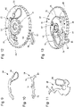
- a jumper 34 provided with an elastic blade 35 is particularly illustrated in figure 9 .
- This jumper 34 is carried by the display wheel 28 and presses a holding element preferably of the type of a holding finger 36 in the toothing 32 of the fixed display wheel 30.
- This holding finger 36 carried by the display wheel 28, is pivotally mounted about a pivot axis 37 and is provided with a beak 38 by which it engages in the toothing 32 of the fixed display wheel 30. It is therefore this finger holding pin 36 which permanently holds the retrograde timepiece display mechanism 1 under the tension produced by the return spring 4.
- This holding finger 36 also comprises (see figure 10 ) a first foot 40 whose role will be detailed later.
- the toothing 32 makes it possible to retain the elastic tension in the counter-clockwise direction and allows the display wheel 28 to advance one step in the clockwise direction. a watch when changing from one date indication to the next date indication.
- the jumper 34 and the holding finger 36 are arranged on either side of a plate 42 of the display wheel 28.
- the jumper 34 acts on the holding finger 36 for example via a first pin 44 carried by the finger of holder 36 and which projects through an opening 46 formed in the plate 42 of the display wheel 28 (see figure 12 ).
- the teeth of the toothing 32 have an inclined wolf-tooth profile to allow the holding finger 36 to pass from an interval between two wolf teeth to the following interval
- the retrograde horological display mechanism 1 must allow this holding finger 36 to go slightly beyond the interval between the two wolf teeth in which it must fall before then being able to return slightly back and fall within this range. It is for this reason that, when passing from one date indication to the following date indication, the display hand 23 goes slightly beyond the date indication on which it must point before coming to position appropriately next to this date indication. During a current month, this does not pose any particular problem because the movement made by the display hand 23 beyond the date indication to which it must point is furtive and almost imperceptible by the owner of the timepiece.
- the clutch release device firstly comprises a display release rocker 48 which is integral display pinion 14, for example by driving. Furthermore, the display disengagement rocker 48 is coupled in rotation with the display wheel 28 by means of a second pin 50 fixed in the plate 42 of this display wheel 28. As can be seen in particular on the figure 11 , the display disengagement rocker 48 also comprises an elastic blade 54 elastically bearing against a third pin 56 fixed in the board 42 of the display wheel 28. The second pin 50 protrudes into an opening 52 provided in the Display disengagement rocker 48. Finally, the display disengagement rocker 48 comprises a second foot 58 whose role will be detailed in the following description.
- the retrograde horological display mechanism 1 begins to change from a date indication to the following date indication.
- a drive wheel 60 driven in a manner known per se by the movement of the timepiece at the rate of one complete revolution in twenty-four hours, drives with it a drive finger 62 which, in turn turn, drives the display wheel 28 one step per day clockwise.
- the holding finger 36 passes from an interval between two successive teeth of the wolf-toothed toothing 32 of the fixed display wheel 30 to the immediately following interval, thus guaranteeing the maintenance under elastic tension of the assembly of the retrograde watchmaking display mechanism 1.
- the drive finger 62 is elastic, so that it can be erased in front of the teeth of the display wheel 28 when the latter rotates in the retrograde direction when the retrograde watch display mechanism 1 returns to its initial position.
- Another advantage offered by the drive finger 62 is that, due to its elasticity, it allows the owner of the timepiece to set the time counter-clockwise without the retrograde watchmaking display mechanism 1 is driven and therefore out of adjustment.
- the display disengagement rocker 48 is integral with the display pinion 14 and, via the second pin 50, is coupled in rotation with the display wheel 28 which is free in rotation with respect to the fixed display wheel. 30. Consequently, the display pinion 14 which is freely mounted coaxially on the display wheel 28 in turn pivots and, via the third idler wheel 12, drives the second idler wheel 10 on which was fixed the display hand 23, so that the display can pass from one indication to the next indication. Similarly, the third pin 56 comes into contact with the elastic blade 54 of the disengagement rocker of the display 48 and drives the latter in rotation.
- the drive finger 62 drives the display wheel 28 and therefore the holding finger 36 which is carried by the display wheel 28 over 11.1°, whereas the angle which separates two consecutive teeth of the wolf-toothed toothing 32 of the fixed display wheel 30 is only 8.57°. It is therefore understood that the holding finger 36 advances more than necessary, this in order to guarantee its correct passage from an interval between two consecutive teeth of the toothing 32 in wolf teeth to the immediately following interval, and therefore the good increment of the information displayed. It should nevertheless be understood that this embodiment should not be interpreted in a limiting manner, in particular as regards the angle values which are functions of the dimensioning of the retrograde horological display mechanism 1.
- the example of the display of the date indications from “1" to "31” is also given for purely illustrative purposes. and not limiting only, and that other time indications can be displayed by the retrograde horological display mechanism 1 according to the invention, so that the speed of rotation of the drive wheel 60 can be different from twenty-four time.
- the drive wheel 60 will make a complete revolution in seven days if the retrograde watch display mechanism 1 according to the invention is used to display the week.
- the drive wheel 60 will make a complete revolution in 31 days if the display mechanism according to the invention is intended to display the months of the year.
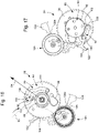
- the retrograde horological display mechanism 1 is of the perpetual calendar type.
- this mechanism comprises a cam 64 on which is fixed a star wheel 66 with twelve teeth which is driven by a second drive finger 68.
- This second drive finger 68 is carried by the return rake 2 provided with its toothed sector 16 engaged with the display pinion 14 and therefore with the movement of the timepiece via the first and second mobiles 20 and 24 and the third deflection wheel 12.
- the return rake 2 rotates one degree per day in the direction of clockwise.
- the second drive finger 68 gradually retracts and comes gradually to position itself behind a given tooth of the star 66.
- the retrograde horological display mechanism 1 is finally completed by a feeler 70 which has four successive bearing surfaces 70a, 70b, 70c and 70d which each correspond to a different duration for the months 28, 29, 30 and 31 days. More precisely, the first bearing surface 70a located furthest at the end of the feeler 70 corresponds to months of 31 days. The second support surface 70b immediately following corresponds to the months of 30 days and the third and fourth support surfaces 70c and 70d which follow correspond to the month of February depending on whether it has 29 days (leap years) or 28 days.
- the feeler 70 bears against the profile of the cam 64 by a follower 72.
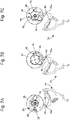
- the retrograde watchmaking display mechanism 1 according to the invention is located in a situation corresponding to the display of the date indications of a 31-day month.
- the holding finger 36 and the disengagement of the display 48 find themselves facing the first support surface 70a of the feeler 70 via their respective feet 40 and 58. In this position, the retrograde timepiece display mechanism 1 is not yet disengaged.
- the holding finger 36 By pivoting, the holding finger 36 will thus go against the elastic force of the jumper 34 and will be able to disengage from the wolf-toothed toothing 32 of the fixed display wheel 30.
- the disengagement rocker of the display 48 being blocked, the elastic blade 54 is, under the effect of the pivoting of display wheel 28, driven by third pin 56 and stretches.
- the holding finger 36 disengages from the wolf-toothed toothing 32 of the fixed display wheel 30
- the retaining force exerted by the elastic blade 54 of the disengagement rocker of the display 48 is released.
- the display of the date indication is linked to the disengagement rocker of the display 48; indeed, the drive wheel 60 drives the display wheel 28 which itself drives the display disengagement rocker 48.
- the retrograde watchmaking display mechanism 1 finds itself in the position illustrated in Figures 7A-7C in which it displays the date indication “1” of the following month.
- the beak 38 of the holding finger 36 is constantly in engagement with the teeth of the toothing 32 in wolf teeth, except when around midnight, this mechanism of the retrograde horological display 1 passes from one date indication to the following date indication and that the holding finger 36 pivots just by the amount necessary to allow its beak 38 to pass from an interval between two teeth of the toothing 32 in wolf teeth at the immediately following interval.
- the foot 40 of the holding finger 36 deviates from the surface of support 70a of feeler 70, so that holding finger 36 tilts and its beak 38 disengages from its grip with toothing 32 in wolf teeth.
- this mechanism will seek to return retrogradely to the date indication "1" which marks the start of a new month, then the beak 38 of the holding finger 36 will once again engage in the teeth of the wolf-toothed toothing 32, which will again ensure the holding in position of the retrograde watchmaking display mechanism 1.
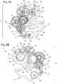
- the figures 8A to 8E illustrate the operation of the retrograde horological display mechanism 1 at the precise moment when it passes from the last date indication of a month to the first date indication of the following month.
- the reset cam 74 whose role consists, when the retrograde watchmaker display mechanism 1 returns to the date indication "1" of the following month, to bring the beak 38 of the holding finger 36 engaged in toothing 32 in wolf teeth.
- this reset cam 74 fixedly mounted on a bridge or a plate of the movement of the timepiece, is provided with a nose 76 against which a homologous appendage 78 provided on the holding finger will slide 36.
- the display wheel 28 rotates, in the top views 8A, 8C and 8E, counterclockwise, carrying with it the finger support 36 which pivots around its pivot axis 37 and whose homologous appendage 78 slides along the fixed nose 76 of the reset cam 74 as is clear from the figure 8B , 8D and 8F .
- the profile of this nose 76 is arranged so that when the retrograde horological display mechanism 1 has returned to its initial position, in other words when it indicates the date indication "1" of the new month, the holding finger 36 has finished pivoting and is again engaged by its beak 38 with the wolf-toothed teeth 32 of the fixed display wheel 30.
- this first pin 44 begins to slide under jumper 34, and at the figure 8E which corresponds to the situation in which the retrograde horological display mechanism 1 has returned to its initial position in which it points to the date indication "1", the first pin 44 has once again passed completely under the jumper 34, this which allows the latter to elastically press the beak 38 of the holding finger 36 into the toothing 32 in wolf teeth.
- the feeler 70 is arranged to be in a position in which the second foot 58 of the rocker disengagement of the display 48 will abut against the second support surface 70b one day earlier than when this second foot 58 abuts against the first support surface 70a corresponding to a month of 31 days. Consequently, the elastic tension will relax and the retrograde timepiece display mechanism 1 will be reset one day earlier than in the case where the second foot 58 abuts against the first support surface 70a.
- the bearing surfaces 70a, 70b, 70c and 70d are four in number and correspond respectively to the months of 31 days, to the months of 30 days and to the month of February which, depending on the case, can be 29 days or 28 days. Consequently, these four bearing surfaces 70a, 70b, 70c and 70d make it possible to provide a retrograde horological display mechanism 1 of the perpetual calendar type.
- bearing surfaces could only be two in number, namely a first bearing surface for the months of 31 days and a second bearing surface for the months of 30 days, which would make it possible to provide a retrograde horological display mechanism 1 of the conventional annual calendar type in which the change of date from February 28 to March 1 does not take place automatically.
- FIG. 14 to 38 A simplified embodiment of the retrograde horological display mechanism of the dragging type according to the invention is illustrated in figures 14 to 38 .
- this retrograde horological display mechanism of the dragging type is shown in its simplified embodiment in top view at the figure 14 and in view from below figure 15 .
- this retrograde horological display mechanism 1 is a simple date display mechanism arranged to display the date indications from “1” to “31” in retrograde fashion.
- the retrograde horological display mechanism 80 comprises a display pinion 82.
- This display pinion 82 is forced to rotate counter-clockwise by a mechanical tension induced by a return element 83 such as a booster rake.
- a display hand 84 moves clockwise opposite an index 86 on which appear the date indications from "1" to "31” (see figure 38 ).
- the retrograde horological display mechanism 80 is completed by a display wheel 88 on which the display pinion 82 is freely mounted and to which it is coaxially coupled.
- the retrograde watchmaking display mechanism 80 further comprises a fixed display wheel 90 provided with toothing 92 preferably of the wolf-tooth type. This fixed display wheel 90 is mounted fixed on a bridge or a plate of the movement of the timepiece (not shown) concentrically to the display pinion 82 and to the display wheel 88.
- a jumper 94 provided with an elastic blade 96 is particularly illustrated in figure 39 .
- This jumper 94 is carried by the display wheel 88 and presses a holding element preferably of the type of a holding finger 98 in the toothing 92 of the fixed display wheel 90.
- This holding finger 98 carried by the display wheel 88, is pivotally mounted about a pivot axis 100 and is provided with a beak 102 by which it engages in the toothing 92 of the fixed display wheel 90. It is therefore this finger holding mechanism 98 which permanently holds the retrograde horological display mechanism 80 against the mechanical tension at which the display pinion 82 is submitted.
- This holding finger 98 also comprises (see figure 40 ) a first foot 104 whose role will be detailed later.
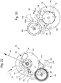
- the toothing 92 makes it possible to retain the elastic tension which is exerted on the display pinion 82 in the counter-clockwise direction and allows the display wheel 88 to advance by one step in clockwise when passing from one date indication to the next date indication ( figures 16 to 21 ).
- the jumper 94 and the holding finger 98 are arranged on either side of a plate 106 of the display wheel 88.
- the jumper 94 acts on the holding finger 98 for example via a first pin 108 carried by the holding finger 98 and which projects through an opening 110 made in the plate 106 of the display wheel 88 (see figure 42 ).
- the mechanism retrograde horological display 80 must allow this holding finger 98 to go slightly beyond the interval between the two wolf teeth in which it must fall before then being able to return slightly back and fall into this interval. It is for this reason that, when passing from one date indication to the following date indication, the display hand 84 goes slightly beyond the date indication on which it must point before coming to position appropriately next to this date indication.
- the display hand 84 provides an erroneous indication, which may lead the owner of the timepiece to believe that the latter suffers from a design defect or is the subject of damage. a malfunction, and in any case the owner has a bad image of his timepiece.
- the present invention provides for equipping the retrograde timepiece display mechanism with a disengagement device which will now be described.
- the disengagement device firstly comprises a display disengagement rocker 112 which is integral display pinion 82, for example by driving. Furthermore, the display disengagement rocker 112 is coupled in rotation with the display wheel 88 by means of a second pin 114 fixed in the plate 106 of this display wheel 88. As visible in particular on the figure 43 , the display disengagement rocker 112 also comprises an elastic blade 116 elastically bearing against a third pin 118 fixed in the plate 106 of the display wheel 88. The second pin 114 protrudes into an opening 120 provided in the Display disengagement rocker 112. Finally, the display disengagement rocker 112 comprises a second foot 122 whose role will be detailed in the following description.
- the retrograde horological display mechanism 80 begins to change from a date indication to indication of next date.
- the display wheel 88 is driven one step per day by the movement of the timepiece in the clockwise direction.
- the holding finger 98 passes from an interval between two successive teeth of the wolf-toothed toothing 92 of the fixed display wheel 90 to the immediately following interval, thus guaranteeing the maintenance under elastic tension of the entire retrograde watchmaking display mechanism 80.
- a drive wheel 126 driven in a manner known per se by the movement of the timepiece at the rate of one complete revolution in twenty-four hours, drives with it a drive finger 128 which, in turn turn, drives the display wheel 88 one step per day in a clockwise direction.
- the holding finger 98 passes from an interval between two successive teeth of the wolf-toothed toothing 92 of the fixed display wheel 90 to the immediately following interval, thus guaranteeing the maintenance under elastic tension of the assembly of the retrograde watchmaking display mechanism 1.
- the drive finger 128 is elastic, so that it can be erased in front of the teeth of the display wheel 88 when the latter rotates in the retrograde direction when the retrograde horological display mechanism 80 returns to its initial position.
- Another advantage offered by the drive finger 128 is that, due to its elasticity, it allows the owner of the timepiece to set the time counter-clockwise without that the retrograde watchmaking display mechanism 80 is driven and therefore disturbed.
- the display disengagement rocker 112 is integral with the display pinion 82 and, via the second pin 114, is coupled in rotation with the display wheel 88 which is free in rotation with respect to the fixed display wheel. 90. Consequently, the display pinion 82 which is freely coaxially mounted on the display wheel 88 in turn pivots and drives the display hand 84, so that the display can pass from one date indication to the following date indication. Similarly, the third pin 118 comes into contact with the elastic blade 116 of the disengagement rocker of the display 112 and drives the latter in rotation.
- the display wheel 88 drives the holding finger 98 which is carried by the display wheel 88 over 11.1°, whereas the angle which separates two consecutive teeth of the toothing 92 in wolf teeth of the fixed display wheel 90 is only 8.57°. It is therefore understood that the holding finger 98 advances more than necessary, this in order to guarantee its correct passage from an interval between two consecutive teeth of the toothing 92 in wolf teeth to the immediately following interval, and therefore the correct increment of the information displayed. It should nevertheless be understood that this embodiment should not be interpreted in a limiting manner, in particular as regards the angle values which are functions of the dimensioning of the retrograde horological display mechanism 80.
- the example of the display of the date indications from “1" to “31” is also given for purely illustrative and non-limiting purposes only, and that other time indications can be displayed by the mechanism of retrograde horological display 80 according to the invention, such that the number of steps taken by the display wheel 88 between two successive returns to the display of the first date indication may be different from thirty-one.
- the display wheel 88 will advance six steps between two successive returns to the display of the indication of the day. " Monday ".
- the display wheel 88 will advance one step per month if the display mechanism according to the invention is intended to display the months of the year.
- this retrograde horological display mechanism 80 is finally supplemented by a period limitation element 124 fixed which has a single support surface 124a which corresponds to the duration of a month of 31 days.
- the retrograde horological display mechanism 80 is in a situation corresponding to the display of the date indications of a month of 31 days.
- the holding finger 98 and the display disengagement rocker 112 find themselves facing the bearing surface 124a of the period limitation 124 via their respective feet 104 and 122.
- the retrograde horological display mechanism 80 when the retrograde horological display mechanism 80 is about to switch again to the date indication "1", the feet 104 and 122 of the holding finger 98 and of the display declutch rocker 112 are in abutment against the support surface 124a of the period limiting element 124 (see figures 24 and 25 ). In this position, the retrograde watch display mechanism 80 is not yet disengaged. Indeed, during the period of time which separates the passage of the display from the date indication “31” to the date indication “1”, the display wheel 88 is in the process of pivoting. By pivoting, this display wheel 88 drives with it via the second pin 114 the display disengagement rocker 112 which, in turn, drives the display pinion 82.
- the display disengagement rocker 112 abuts by its foot 122 against the support surface 124a of the period limiting element 124 and remains blocked (see figures 26 and 27 ).
- the holding finger 98 driven by the display wheel 88, it abuts by its foot 104 against this same support surface 124a of the period limiting element 124, which forces this holding finger 98 to pivot around its pivot axis 100.
- the Holding finger 98 will thus go against the elastic force of the jumper 94 and will be able to disengage from the wolf-toothed toothing 92 of the fixed display wheel 90.
- the display of the date indication is linked to the disengagement rocker of the display 112; in fact, by pivoting, the display wheel 88 itself drives the display disengagement rocker 112.
- the beak 102 of the holding finger 98 is constantly in engagement with the teeth of the toothing 92 in wolf teeth, except when around midnight, this mechanism of retrograde horological display 80 passes from one date indication to the following date indication and that the holding finger 98 pivots just by the amount necessary to allow its beak 102 to pass from an interval between two teeth of the toothing 92 in wolf teeth at the immediately following interval ( figures 16 and 17 ).
- the foot 104 of the holding finger 98 moves away from the support surface 124a of the period limiting element 124, so that the holding finger 98 tilts and its beak 102 disengages from its grip with toothing 92 in wolf teeth ( figures 26 and 27 ).
- the figures 24 to 31 illustrate the operation of the retrograde horological display mechanism 80 at the precise moment when it goes retrograde from the date indication “31” to the date indication “1”. This movement is assisted by the cooperation between the holding finger 98 and the jumper 94. Indeed, by carefully observing the figure 26 , 28 , 30 , 32 , 34 and 36 , we see that the first pin 108 carried by the holding finger 98 gradually changes plane of contact with the jumper 94.
- this first pin 108 begins to slide under jumper 94, and at the figure 36 which corresponds to the situation in which the retrograde horological display mechanism 80 has returned to its position initial in which it points to the date indication "1", the first pin 108 is again completely passed under the jumper 94, which allows the latter to elastically press the beak 102 of the holding finger 98 into the toothing 92 in wolf teeth.
Landscapes
- Physics & Mathematics (AREA)
- General Physics & Mathematics (AREA)
- Geometry (AREA)
- Measurement Of Unknown Time Intervals (AREA)
- Electromechanical Clocks (AREA)
Applications Claiming Priority (1)
| Application Number | Priority Date | Filing Date | Title |
|---|---|---|---|
| EP20217232.6A EP4020099A1 (de) | 2020-12-24 | 2020-12-24 | Retrograder anzeigemechanismus für uhr vom schleppzeigertyp, der mit einer kupplungswippe der anzeige ausgestattet ist |
Publications (2)
| Publication Number | Publication Date |
|---|---|
| EP3989011A1 true EP3989011A1 (de) | 2022-04-27 |
| EP3989011B1 EP3989011B1 (de) | 2023-06-14 |
Family
ID=73943173
Family Applications (2)
| Application Number | Title | Priority Date | Filing Date |
|---|---|---|---|
| EP20217232.6A Withdrawn EP4020099A1 (de) | 2020-12-24 | 2020-12-24 | Retrograder anzeigemechanismus für uhr vom schleppzeigertyp, der mit einer kupplungswippe der anzeige ausgestattet ist |
| EP21200062.4A Active EP3989011B1 (de) | 2020-12-24 | 2021-09-30 | Retrograder uhranzeigemechanismus vom schleppzeigertyp, der mit einer kupplungswippe der anzeige ausgestattet ist |
Family Applications Before (1)
| Application Number | Title | Priority Date | Filing Date |
|---|---|---|---|
| EP20217232.6A Withdrawn EP4020099A1 (de) | 2020-12-24 | 2020-12-24 | Retrograder anzeigemechanismus für uhr vom schleppzeigertyp, der mit einer kupplungswippe der anzeige ausgestattet ist |
Country Status (4)
| Country | Link |
|---|---|
| US (1) | US20220206436A1 (de) |
| EP (2) | EP4020099A1 (de) |
| JP (1) | JP7274552B2 (de) |
| CN (1) | CN114675522A (de) |
Families Citing this family (1)
| Publication number | Priority date | Publication date | Assignee | Title |
|---|---|---|---|---|
| CN117826559B (zh) * | 2024-01-12 | 2024-09-13 | 深圳市贝伦斯智能穿戴科技有限公司 | 一种逆跳微调机构 |
Citations (4)
| Publication number | Priority date | Publication date | Assignee | Title |
|---|---|---|---|---|
| EP1918792A1 (de) * | 2006-11-06 | 2008-05-07 | Compagnie des Montres Longines, Francillon SA | Uhr, die einen Korrekturmechanismus für eine Vorrichtung zur Anzeige einer Zeitgröße umfasst |
| EP1134627B1 (de) * | 2000-03-16 | 2008-05-14 | Roger Dubuis S.A. Manufacture | Dreifache rückläufige Anzeige und deren Mechanismus |
| CH704915A2 (fr) * | 2011-05-11 | 2012-11-15 | Manuf La Joux Perret Sa | Dispositif d'affichage sautant amélioré. |
| CH711768A2 (fr) * | 2015-11-10 | 2017-05-15 | Impulsion Sa | Dispositif d'embrayage bidirectionnel à débrayage dynamométrique unidirectionnel pour pièce d'horlogerie. |
Family Cites Families (7)
| Publication number | Priority date | Publication date | Assignee | Title |
|---|---|---|---|---|
| JP4453645B2 (ja) * | 2005-01-24 | 2010-04-21 | セイコーエプソン株式会社 | 時計の表示装置、ムーブメント、および時計 |
| JP6004857B2 (ja) * | 2012-09-20 | 2016-10-12 | セイコーインスツル株式会社 | 表示機構、時計用ムーブメント、及び機械式時計 |
| EP3540522B1 (de) * | 2018-03-13 | 2020-10-28 | Harry Winston SA | Retrograder anzeigemechanismus für uhr |
| CH714747B1 (fr) * | 2018-03-13 | 2024-06-28 | Montres Breguet Sa | Mécanisme d'affichage d'horlogerie sautant et régulé. |
| EP3637197B1 (de) * | 2018-10-12 | 2021-05-19 | Blancpain SA | Vorrichtung zur regulierung der retrograden anzeige einer uhr |
| EP3667434B1 (de) * | 2018-12-10 | 2021-08-04 | Montres Breguet S.A. | Grossanzeigemechanismus für datum, und mit einem solchen mechanismus ausgestattete uhr |
| EP3839657A1 (de) * | 2019-12-16 | 2021-06-23 | Montres Breguet S.A. | On-demand-anzeigemechanismus für uhr |
-
2020
- 2020-12-24 EP EP20217232.6A patent/EP4020099A1/de not_active Withdrawn
-
2021
- 2021-09-30 EP EP21200062.4A patent/EP3989011B1/de active Active
- 2021-10-05 US US17/494,159 patent/US20220206436A1/en active Pending
- 2021-11-12 JP JP2021184493A patent/JP7274552B2/ja active Active
- 2021-12-24 CN CN202111607256.5A patent/CN114675522A/zh active Pending
Patent Citations (4)
| Publication number | Priority date | Publication date | Assignee | Title |
|---|---|---|---|---|
| EP1134627B1 (de) * | 2000-03-16 | 2008-05-14 | Roger Dubuis S.A. Manufacture | Dreifache rückläufige Anzeige und deren Mechanismus |
| EP1918792A1 (de) * | 2006-11-06 | 2008-05-07 | Compagnie des Montres Longines, Francillon SA | Uhr, die einen Korrekturmechanismus für eine Vorrichtung zur Anzeige einer Zeitgröße umfasst |
| CH704915A2 (fr) * | 2011-05-11 | 2012-11-15 | Manuf La Joux Perret Sa | Dispositif d'affichage sautant amélioré. |
| CH711768A2 (fr) * | 2015-11-10 | 2017-05-15 | Impulsion Sa | Dispositif d'embrayage bidirectionnel à débrayage dynamométrique unidirectionnel pour pièce d'horlogerie. |
Also Published As
| Publication number | Publication date |
|---|---|
| US20220206436A1 (en) | 2022-06-30 |
| CN114675522A (zh) | 2022-06-28 |
| EP3989011B1 (de) | 2023-06-14 |
| JP2022101476A (ja) | 2022-07-06 |
| JP7274552B2 (ja) | 2023-05-16 |
| EP4020099A1 (de) | 2022-06-29 |
Similar Documents
| Publication | Publication Date | Title |
|---|---|---|
| EP1586962B1 (de) | Perpetual calendar mechanism | |
| EP1785783B1 (de) | Jahreskalendermechanismus für Uhrwerk | |
| EP2751623B1 (de) | Antriebsmechanismus eines anzeigers | |
| EP2180383B1 (de) | Hilfsvorrichtung zur Positionshaltung einer Datumsanzeigescheibe für Uhrwerk | |
| EP2115537A2 (de) | Zeitmessgerät mit einem mechanismus zum betrieb einer vorrichtung zur anzeige eines zeitbezogenen wertes | |
| EP3009893B1 (de) | Ewiger Kalender mit Ausgleichsgetriebe | |
| EP2407833A1 (de) | Spielausgleichsmechanismus für Uhrwerk | |
| CH681761B5 (fr) | Pièce d'horlogerie du type mécanique et/ou électromécanique, pourvue de moyens d'affichage à déplacement retrograde automatique. | |
| EP0987609B1 (de) | Jährlicher Kalendermechanismus für Uhrwerk | |
| EP3989011B1 (de) | Retrograder uhranzeigemechanismus vom schleppzeigertyp, der mit einer kupplungswippe der anzeige ausgestattet ist | |
| EP3913442B1 (de) | Retrograder uhranzeigemechanismus, der mit einer sicherheitsvorrichtung ausgestattet ist | |
| CH712222A2 (fr) | Roue d'entraînement d'indicateur de date, mécanisme de calendrier, mouvement et pièce d'horlogerie. | |
| CH715809A1 (fr) | Pièce d'horlogerie comportant un affichage à pas variable. | |
| EP0606576B1 (de) | Islamitischer Kalender | |
| CH699794B1 (fr) | Dispositif d'aide au maintien en position d'un anneau indicateur de quantième pour pièce d'horlogerie. | |
| EP3776095A1 (de) | Jahreskalendermechanismus | |
| CH718166A2 (fr) | Mécanisme d'affichage horloger rétrograde de type traînant équipé d'une bascule de débrayage de l'affichage. | |
| CH691088A5 (fr) | Mécanisme de mise à l'heure d'un mouvement d'horlogerie à quantième perpétuel. | |
| EP3460588B1 (de) | Datumsmechanismus | |
| EP3644130B1 (de) | Datumsmechanismus | |
| EP3667435B1 (de) | Einstellsystem der position eines ersten gezahnten drehteils in bezug auf eine halterung, auf der dieser ersten gezahnten drehteil drehbar befestigt ist, und uhr, die ein solches system umfasst | |
| CH689601A5 (fr) | Mécanisme de quantième pour mouvement d'horlogerie. | |
| CH718804A1 (fr) | Mécanisme de quantième perpétuel ou annuel. | |
| CH712123A2 (fr) | Mécanisme de calendrier, mouvement et pièce d'horlogerie. | |
| CH717011B1 (fr) | Mécanisme d'affichage horloger rétrograde muni d'un dispositif de sécurité. |
Legal Events
| Date | Code | Title | Description |
|---|---|---|---|
| PUAI | Public reference made under article 153(3) epc to a published international application that has entered the european phase |
Free format text: ORIGINAL CODE: 0009012 |
|
| STAA | Information on the status of an ep patent application or granted ep patent |
Free format text: STATUS: THE APPLICATION HAS BEEN PUBLISHED |
|
| AK | Designated contracting states |
Kind code of ref document: A1 Designated state(s): AL AT BE BG CH CY CZ DE DK EE ES FI FR GB GR HR HU IE IS IT LI LT LU LV MC MK MT NL NO PL PT RO RS SE SI SK SM TR |
|
| STAA | Information on the status of an ep patent application or granted ep patent |
Free format text: STATUS: REQUEST FOR EXAMINATION WAS MADE |
|
| 17P | Request for examination filed |
Effective date: 20221027 |
|
| RBV | Designated contracting states (corrected) |
Designated state(s): AL AT BE BG CH CY CZ DE DK EE ES FI FR GB GR HR HU IE IS IT LI LT LU LV MC MK MT NL NO PL PT RO RS SE SI SK SM TR |
|
| GRAP | Despatch of communication of intention to grant a patent |
Free format text: ORIGINAL CODE: EPIDOSNIGR1 |
|
| STAA | Information on the status of an ep patent application or granted ep patent |
Free format text: STATUS: GRANT OF PATENT IS INTENDED |
|
| INTG | Intention to grant announced |
Effective date: 20230317 |
|
| GRAS | Grant fee paid |
Free format text: ORIGINAL CODE: EPIDOSNIGR3 |
|
| GRAA | (expected) grant |
Free format text: ORIGINAL CODE: 0009210 |
|
| STAA | Information on the status of an ep patent application or granted ep patent |
Free format text: STATUS: THE PATENT HAS BEEN GRANTED |
|
| AK | Designated contracting states |
Kind code of ref document: B1 Designated state(s): AL AT BE BG CH CY CZ DE DK EE ES FI FR GB GR HR HU IE IS IT LI LT LU LV MC MK MT NL NO PL PT RO RS SE SI SK SM TR |
|
| REG | Reference to a national code |
Ref country code: CH Ref legal event code: EP |
|
| REG | Reference to a national code |
Ref country code: DE Ref legal event code: R096 Ref document number: 602021002928 Country of ref document: DE |
|
| REG | Reference to a national code |
Ref country code: AT Ref legal event code: REF Ref document number: 1579667 Country of ref document: AT Kind code of ref document: T Effective date: 20230715 |
|
| P01 | Opt-out of the competence of the unified patent court (upc) registered |
Effective date: 20230611 |
|
| REG | Reference to a national code |
Ref country code: LT Ref legal event code: MG9D |
|
| REG | Reference to a national code |
Ref country code: NL Ref legal event code: MP Effective date: 20230614 |
|
| PG25 | Lapsed in a contracting state [announced via postgrant information from national office to epo] |
Ref country code: SE Free format text: LAPSE BECAUSE OF FAILURE TO SUBMIT A TRANSLATION OF THE DESCRIPTION OR TO PAY THE FEE WITHIN THE PRESCRIBED TIME-LIMIT Effective date: 20230614 Ref country code: NO Free format text: LAPSE BECAUSE OF FAILURE TO SUBMIT A TRANSLATION OF THE DESCRIPTION OR TO PAY THE FEE WITHIN THE PRESCRIBED TIME-LIMIT Effective date: 20230914 Ref country code: ES Free format text: LAPSE BECAUSE OF FAILURE TO SUBMIT A TRANSLATION OF THE DESCRIPTION OR TO PAY THE FEE WITHIN THE PRESCRIBED TIME-LIMIT Effective date: 20230614 |
|
| REG | Reference to a national code |
Ref country code: AT Ref legal event code: MK05 Ref document number: 1579667 Country of ref document: AT Kind code of ref document: T Effective date: 20230614 |
|
| PG25 | Lapsed in a contracting state [announced via postgrant information from national office to epo] |
Ref country code: RS Free format text: LAPSE BECAUSE OF FAILURE TO SUBMIT A TRANSLATION OF THE DESCRIPTION OR TO PAY THE FEE WITHIN THE PRESCRIBED TIME-LIMIT Effective date: 20230614 Ref country code: NL Free format text: LAPSE BECAUSE OF FAILURE TO SUBMIT A TRANSLATION OF THE DESCRIPTION OR TO PAY THE FEE WITHIN THE PRESCRIBED TIME-LIMIT Effective date: 20230614 Ref country code: LV Free format text: LAPSE BECAUSE OF FAILURE TO SUBMIT A TRANSLATION OF THE DESCRIPTION OR TO PAY THE FEE WITHIN THE PRESCRIBED TIME-LIMIT Effective date: 20230614 Ref country code: LT Free format text: LAPSE BECAUSE OF FAILURE TO SUBMIT A TRANSLATION OF THE DESCRIPTION OR TO PAY THE FEE WITHIN THE PRESCRIBED TIME-LIMIT Effective date: 20230614 Ref country code: HR Free format text: LAPSE BECAUSE OF FAILURE TO SUBMIT A TRANSLATION OF THE DESCRIPTION OR TO PAY THE FEE WITHIN THE PRESCRIBED TIME-LIMIT Effective date: 20230614 Ref country code: GR Free format text: LAPSE BECAUSE OF FAILURE TO SUBMIT A TRANSLATION OF THE DESCRIPTION OR TO PAY THE FEE WITHIN THE PRESCRIBED TIME-LIMIT Effective date: 20230915 |
|
| PGFP | Annual fee paid to national office [announced via postgrant information from national office to epo] |
Ref country code: FR Payment date: 20230822 Year of fee payment: 3 Ref country code: DE Payment date: 20230822 Year of fee payment: 3 |
|
| PG25 | Lapsed in a contracting state [announced via postgrant information from national office to epo] |
Ref country code: FI Free format text: LAPSE BECAUSE OF FAILURE TO SUBMIT A TRANSLATION OF THE DESCRIPTION OR TO PAY THE FEE WITHIN THE PRESCRIBED TIME-LIMIT Effective date: 20230614 |
|
| PG25 | Lapsed in a contracting state [announced via postgrant information from national office to epo] |
Ref country code: SK Free format text: LAPSE BECAUSE OF FAILURE TO SUBMIT A TRANSLATION OF THE DESCRIPTION OR TO PAY THE FEE WITHIN THE PRESCRIBED TIME-LIMIT Effective date: 20230614 |
|
| PG25 | Lapsed in a contracting state [announced via postgrant information from national office to epo] |
Ref country code: IS Free format text: LAPSE BECAUSE OF FAILURE TO SUBMIT A TRANSLATION OF THE DESCRIPTION OR TO PAY THE FEE WITHIN THE PRESCRIBED TIME-LIMIT Effective date: 20231014 |
|
| PG25 | Lapsed in a contracting state [announced via postgrant information from national office to epo] |
Ref country code: SM Free format text: LAPSE BECAUSE OF FAILURE TO SUBMIT A TRANSLATION OF THE DESCRIPTION OR TO PAY THE FEE WITHIN THE PRESCRIBED TIME-LIMIT Effective date: 20230614 Ref country code: SK Free format text: LAPSE BECAUSE OF FAILURE TO SUBMIT A TRANSLATION OF THE DESCRIPTION OR TO PAY THE FEE WITHIN THE PRESCRIBED TIME-LIMIT Effective date: 20230614 Ref country code: RO Free format text: LAPSE BECAUSE OF FAILURE TO SUBMIT A TRANSLATION OF THE DESCRIPTION OR TO PAY THE FEE WITHIN THE PRESCRIBED TIME-LIMIT Effective date: 20230614 Ref country code: PT Free format text: LAPSE BECAUSE OF FAILURE TO SUBMIT A TRANSLATION OF THE DESCRIPTION OR TO PAY THE FEE WITHIN THE PRESCRIBED TIME-LIMIT Effective date: 20231016 Ref country code: IS Free format text: LAPSE BECAUSE OF FAILURE TO SUBMIT A TRANSLATION OF THE DESCRIPTION OR TO PAY THE FEE WITHIN THE PRESCRIBED TIME-LIMIT Effective date: 20231014 Ref country code: EE Free format text: LAPSE BECAUSE OF FAILURE TO SUBMIT A TRANSLATION OF THE DESCRIPTION OR TO PAY THE FEE WITHIN THE PRESCRIBED TIME-LIMIT Effective date: 20230614 Ref country code: CZ Free format text: LAPSE BECAUSE OF FAILURE TO SUBMIT A TRANSLATION OF THE DESCRIPTION OR TO PAY THE FEE WITHIN THE PRESCRIBED TIME-LIMIT Effective date: 20230614 Ref country code: AT Free format text: LAPSE BECAUSE OF FAILURE TO SUBMIT A TRANSLATION OF THE DESCRIPTION OR TO PAY THE FEE WITHIN THE PRESCRIBED TIME-LIMIT Effective date: 20230614 |
|
| PG25 | Lapsed in a contracting state [announced via postgrant information from national office to epo] |
Ref country code: PL Free format text: LAPSE BECAUSE OF FAILURE TO SUBMIT A TRANSLATION OF THE DESCRIPTION OR TO PAY THE FEE WITHIN THE PRESCRIBED TIME-LIMIT Effective date: 20230614 |
|
| REG | Reference to a national code |
Ref country code: DE Ref legal event code: R097 Ref document number: 602021002928 Country of ref document: DE |
|
| PLBE | No opposition filed within time limit |
Free format text: ORIGINAL CODE: 0009261 |
|
| STAA | Information on the status of an ep patent application or granted ep patent |
Free format text: STATUS: NO OPPOSITION FILED WITHIN TIME LIMIT |
|
| PG25 | Lapsed in a contracting state [announced via postgrant information from national office to epo] |
Ref country code: DK Free format text: LAPSE BECAUSE OF FAILURE TO SUBMIT A TRANSLATION OF THE DESCRIPTION OR TO PAY THE FEE WITHIN THE PRESCRIBED TIME-LIMIT Effective date: 20230614 |
|
| PG25 | Lapsed in a contracting state [announced via postgrant information from national office to epo] |
Ref country code: SI Free format text: LAPSE BECAUSE OF FAILURE TO SUBMIT A TRANSLATION OF THE DESCRIPTION OR TO PAY THE FEE WITHIN THE PRESCRIBED TIME-LIMIT Effective date: 20230614 |
|
| PG25 | Lapsed in a contracting state [announced via postgrant information from national office to epo] |
Ref country code: LU Free format text: LAPSE BECAUSE OF NON-PAYMENT OF DUE FEES Effective date: 20230930 |
|
| 26N | No opposition filed |
Effective date: 20240315 |
|
| REG | Reference to a national code |
Ref country code: BE Ref legal event code: MM Effective date: 20230930 |
|
| PG25 | Lapsed in a contracting state [announced via postgrant information from national office to epo] |
Ref country code: SI Free format text: LAPSE BECAUSE OF FAILURE TO SUBMIT A TRANSLATION OF THE DESCRIPTION OR TO PAY THE FEE WITHIN THE PRESCRIBED TIME-LIMIT Effective date: 20230614 Ref country code: LU Free format text: LAPSE BECAUSE OF NON-PAYMENT OF DUE FEES Effective date: 20230930 Ref country code: IT Free format text: LAPSE BECAUSE OF FAILURE TO SUBMIT A TRANSLATION OF THE DESCRIPTION OR TO PAY THE FEE WITHIN THE PRESCRIBED TIME-LIMIT Effective date: 20230614 Ref country code: MC Free format text: LAPSE BECAUSE OF FAILURE TO SUBMIT A TRANSLATION OF THE DESCRIPTION OR TO PAY THE FEE WITHIN THE PRESCRIBED TIME-LIMIT Effective date: 20230614 |
|
| REG | Reference to a national code |
Ref country code: IE Ref legal event code: MM4A |
|
| PG25 | Lapsed in a contracting state [announced via postgrant information from national office to epo] |
Ref country code: IE Free format text: LAPSE BECAUSE OF NON-PAYMENT OF DUE FEES Effective date: 20230930 |
|
| PG25 | Lapsed in a contracting state [announced via postgrant information from national office to epo] |
Ref country code: IE Free format text: LAPSE BECAUSE OF NON-PAYMENT OF DUE FEES Effective date: 20230930 |
|
| PG25 | Lapsed in a contracting state [announced via postgrant information from national office to epo] |
Ref country code: BE Free format text: LAPSE BECAUSE OF NON-PAYMENT OF DUE FEES Effective date: 20230930 |