EP3988979A1 - Optical fiber cable - Google Patents
Optical fiber cable Download PDFInfo
- Publication number
- EP3988979A1 EP3988979A1 EP21215417.3A EP21215417A EP3988979A1 EP 3988979 A1 EP3988979 A1 EP 3988979A1 EP 21215417 A EP21215417 A EP 21215417A EP 3988979 A1 EP3988979 A1 EP 3988979A1
- Authority
- EP
- European Patent Office
- Prior art keywords
- optical fiber
- filling
- core
- inner filling
- fiber cable
- Prior art date
- Legal status (The legal status is an assumption and is not a legal conclusion. Google has not performed a legal analysis and makes no representation as to the accuracy of the status listed.)
- Pending
Links
Images


Classifications
-
- G—PHYSICS
- G02—OPTICS
- G02B—OPTICAL ELEMENTS, SYSTEMS OR APPARATUS
- G02B6/00—Light guides; Structural details of arrangements comprising light guides and other optical elements, e.g. couplings
- G02B6/44—Mechanical structures for providing tensile strength and external protection for fibres, e.g. optical transmission cables
- G02B6/4401—Optical cables
- G02B6/441—Optical cables built up from sub-bundles
-
- G—PHYSICS
- G02—OPTICS
- G02B—OPTICAL ELEMENTS, SYSTEMS OR APPARATUS
- G02B6/00—Light guides; Structural details of arrangements comprising light guides and other optical elements, e.g. couplings
- G02B6/44—Mechanical structures for providing tensile strength and external protection for fibres, e.g. optical transmission cables
- G02B6/4401—Optical cables
- G02B6/4403—Optical cables with ribbon structure
- G02B6/4404—Multi-podded
-
- G—PHYSICS
- G02—OPTICS
- G02B—OPTICAL ELEMENTS, SYSTEMS OR APPARATUS
- G02B6/00—Light guides; Structural details of arrangements comprising light guides and other optical elements, e.g. couplings
- G02B6/44—Mechanical structures for providing tensile strength and external protection for fibres, e.g. optical transmission cables
- G02B6/4401—Optical cables
- G02B6/4429—Means specially adapted for strengthening or protecting the cables
- G02B6/443—Protective covering
- G02B6/4432—Protective covering with fibre reinforcements
-
- G—PHYSICS
- G02—OPTICS
- G02B—OPTICAL ELEMENTS, SYSTEMS OR APPARATUS
- G02B6/00—Light guides; Structural details of arrangements comprising light guides and other optical elements, e.g. couplings
- G02B6/44—Mechanical structures for providing tensile strength and external protection for fibres, e.g. optical transmission cables
- G02B6/4401—Optical cables
- G02B6/4429—Means specially adapted for strengthening or protecting the cables
- G02B6/4434—Central member to take up tensile loads
-
- G—PHYSICS
- G02—OPTICS
- G02B—OPTICAL ELEMENTS, SYSTEMS OR APPARATUS
- G02B6/00—Light guides; Structural details of arrangements comprising light guides and other optical elements, e.g. couplings
- G02B6/44—Mechanical structures for providing tensile strength and external protection for fibres, e.g. optical transmission cables
- G02B6/4401—Optical cables
- G02B6/4429—Means specially adapted for strengthening or protecting the cables
- G02B6/44384—Means specially adapted for strengthening or protecting the cables the means comprising water blocking or hydrophobic materials
-
- G—PHYSICS
- G02—OPTICS
- G02B—OPTICAL ELEMENTS, SYSTEMS OR APPARATUS
- G02B6/00—Light guides; Structural details of arrangements comprising light guides and other optical elements, e.g. couplings
- G02B6/46—Processes or apparatus adapted for installing or repairing optical fibres or optical cables
- G02B6/48—Overhead installation
- G02B6/483—Installation of aerial type
Definitions
- the present invention relates to an optical fiber cable.
- optical fiber cables as disclosed in JP 2014-219494 A and JP 2014-139609 A are known. These optical fiber cables are configured by accommodating a plurality of optical fibers in a sheath.
- EP 0 286 349 A2 discloses an optical fiber cable that includes optical fiber units, a tubular member, an absorbing tape, a corrugated metallic shield and a plastic jacket. A water blocking material is disposed in the inner space of the tubular member to fill the core.
- US 2003/049002 A1 concerns an optical fiber cable that includes optical fibers, a filling material, a central plastic tube, a water blocking tape and an outer sheath.
- the filling material is typically a jelly-like material that has a viscosity sufficiently low to be easily introduced into the buffer tubes during the manufacturing process and to allow a substantially free relative movement of the fibers, but sufficiently high in order to oppose a sufficient physical barrier against the longitudinal flow of water.
- JP 2017 049510 A describes a rectangular-shaped optical fiber cable that includes an optical fiber ribbon, a pair of intervention tapes, a pair of intervention cords and a cable jacket. No wrapping tube is provided.
- a core may be formed by wrapping a plurality of optical fibers and a filling with a press winding tape (also referred to simply as a wrapping tube), and the core may be accommodated in a sheath. Further, the use of filling having water absorbency may prevent water from running in the optical fiber cable.
- An object of the present invention is to provide an optical fiber cable having stable waterproof performance.
- an optical fiber cable includes a core including a plurality of optical fibers, an inner filling, and a wrapping tube which wraps the plurality of optical fibers and the inner filling; an outer filling that is disposed outside the core; and a sheath that covers the core and the outer filling, wherein the plurality of optical fibers are twisted together, Wherein grooves between adjacent optical fibers are formed on an outer periphery of a bundle of the plurality of optical fibers, and wherein the inner filling is disposed to cross the grooves.
- an optical fiber cable having stable waterproof performance due to an outer filling and an inner filling.
- an optical fiber cable includes a core including a plurality of optical fibers, an inner filling, and a wrapping tube which wraps the plurality of optical fibers and the inner filling; an outer filling that is disposed outside the core; a pair of tension members disposed so as to sandwich the core; and a sheath that covers the core, the outer filling, and the pair of tension members, in which the outer filling is longitudinally attached to the outside of the core, and the inner filling is twisted and disposed in an SZ manner inside the core.
- the fillings can be prevented from being unevenly disposed in the optical fiber cable, and local deterioration of the waterproof property can be suppressed.
- the wrapping tube prefferably wound so as to have an overlapping area of both edges of the wrapping tube, and for the outer filling to be disposed at a position not adjacent to the overlapping area of the wrapping tube.
- the outer filling can be suppressed from entering the inside of the wrapping tube from the overlapping area of the wrapping tube.
- the outer filling prefferably be disposed on the opposite side of the overlapping area of the wrapping tube as viewed from the core.
- the outer filling can be further suppressed from entering the inside of the wrapping tube from the overlapping area of the wrapping tube.
- the outer filling prefferably be disposed closer to the outside edge of the wrapping tube which is outside of the overlapping area.
- the outer filling can be further suppressed from entering the inside of the wrapping tube from the overlapping area of the wrapping tube.
- the plurality of optical fibers prefferably be twisted and arranged in the SZ manner.
- the transmission loss of the optical fiber can be suppressed.
- the inner filling prefferably be twisted in the SZ manner together with the plurality of optical fibers.
- both the inner filling and the plurality of optical fibers can be twisted in the SZ manner.
- the inner filling prefferably be disposed so as to cross SZ-shaped gaps of the optical fibers.
- the running of water in the gaps of the optical fibers can be suppressed.
- phase of the SZ-shaped twist of the inner filling is shifted by 180 degrees with respect to the SZ-shaped twist of the optical fiber.
- running of water in the gaps of the optical fibers can be further suppressed.
- a method of manufacturing an optical fiber cable in which a core is formed by wrapping a plurality of optical fibers twisted in an SZ manner and an inner filling with a wrapping tube, and an outer filling longitudinally attached to the outside of the core and a pair of tension members arranged so as to sandwich the core are collectively covered with a sheath is provided.
- the fillings can be prevented from being unevenly disposed in the optical fiber cable, and local deterioration of the waterproof property can be suppressed.
- both the inner filling and the plurality of optical fibers can be twisted in the SZ manner by a simple method.
- the twist of the inner filling can be arbitrarily set with respect to the twist of the optical fiber.
- the inner filling prefferably be twisted in the SZ manner by attaching the inner filling along the longitudinal direction to the outer periphery of the plurality of optical fibers twisted in the SZ manner.
- the inner filling can be twisted in the SZ manner by a simple method.
- the inner filling prefferably be twisted in an SZ manner in the direction opposite to the twisting direction of the plurality of optical fibers by attaching the inner filling along the longitudinal direction to the outer peripheries of the plurality of optical fibers twisted in the SZ manner, and untwisting the plurality of optical fibers.
- phase of the SZ-shaped twist of the inner filling can be shifted by 180 degrees with respect to the SZ-shaped twist of the optical fiber, and running of water in the gaps of the optical fibers can be suppressed.
- FIG. 1 is a cross-sectional view (hereinafter simply referred to as "transverse cross-sectional view”) orthogonal to the longitudinal direction of the optical fiber cable 100 of the first embodiment.
- the longitudinal direction of the optical fiber cable 100 is simply referred to as the longitudinal direction, and is represented by the X axis.
- the optical fiber cable 100 includes a main body portion having a core 3 and a support wire portion having a support wire 50.
- the main body portion and the support wire portion are each formed in a substantially circular shape in a transverse cross-sectional view.
- the outer diameter of the main body portion is larger than the outer diameter of the support wire portion.
- the support wire portion is configured by covering the support wire 50 made of a steel wire or the like with a sheath 60 (second covering portion 60B).
- the support wire portion and the main body portion are connected by the sheath 60 (connecting portion 60C).
- connecting portion 60C By cutting the connecting portion 60C, the main body portion and the support wire portion can be separated.
- both of the optical fiber cable with the supporting wire and the optical fiber cable only including the main body portion without the support wire portion are simply referred to as the "optical fiber cable 100".
- the optical fiber cable 100 includes a core 3 having an optical fiber unit 10, a pair of tension members 20, and a sheath 60.
- the optical fiber cable 100 of the present embodiment includes an inner filling 40A and an outer filling 40B.
- the optical fiber unit 10 is configured with a plurality of optical fibers 1 (optical fiber core wires).
- the optical fiber unit 10 is configured with a plurality of intermittently-adhered optical fiber ribbons (intermittently-fixed optical fiber ribbons).
- FIGS. 2A and 2B are explanatory views of an intermittently-adhered optical fiber ribbon.
- the intermittently-adhered optical fiber ribbon is an optical fiber ribbon in which a plurality of optical fibers 1 are arranged in parallel with each other, and are intermittently connected.
- the direction in which the plurality of optical fibers 1 are arranged in parallel is referred to as the ribbon width direction.
- a connecting portion 11 which connect two adjacent optical fibers 1 are connected by a connecting portion 11.
- a plurality of connecting portions 11 which connect two adjacent optical fibers 1 are intermittently disposed in the longitudinal direction.
- the plurality of connecting portions 11 of the optical fiber ribbon are intermittently disposed two-dimensionally in the longitudinal direction and the ribbon width direction.
- the connecting portions 11 are formed by applying an ultraviolet curing resin as an adhesive to the optical fibers 1 arranged in parallel and then irradiating and solidifying the fibers with ultraviolet rays.
- the connecting portions 11 may be made of a thermoplastic resin.
- a region other than the connecting portion 11 between two adjacent optical fibers 1 is a non-connecting portion 12 (separation portion).
- the non-connecting portion 12 two adjacent optical fibers 1 are not connected.
- the connecting portions 11 and the non-connecting portions 12 are alternately arranged in the ribbon width direction.
- the optical fiber ribbon can be spread in a mesh shape as shown in Fig. 2B by applying force to the ribbon so that it spreads in the width direction of the ribbon. Further, the optical fiber ribbon can be rolled into a bundle, and a large number of optical fibers 1 can be accommodated at a high density.
- two adjacent optical fibers 1 may be in contact with or separated from each other.
- FIGS. 3A and 3B are explanatory views of another intermittently-adhered optical fiber ribbon.
- the intermittently-adhered optical fiber ribbon includes a plurality of (here, four) pairs of optical fibers 1 (fiber pairs) connected along the longitudinal direction. Adjacent fiber pairs are intermittently connected by the connecting portions 11. Also, in this intermittently-adhered optical fiber ribbon, the connecting portions 11 and the non-connecting portions 12 are alternately arranged in the ribbon width direction. Through this, it is possible to spread the optical fiber ribbon in a mesh shape, or to roll the fiber pairs into a bundle.
- the configuration of the intermittently-adhered optical fiber ribbon is not limited to that shown in drawings.
- the arrangement of the connecting portions 11 may be changed, or the number of optical fibers 1 may be changed.
- the configuration of the optical fiber unit 10 may be changed as appropriate.
- the optical fiber unit 10 may be configured by bundling a plurality of single optical fibers 1.
- the core 3 includes the optical fiber unit 10 and a wrapping tube 2 (press winding tape). Specifically, the core 3 is formed by wrapping the optical fiber unit 10 with the wrapping tube 2. In the present embodiment, the core 3 further has an inner filling 40A. The inner filling 40A is disposed inside the wrapping tube 2.
- the wrapping tube 2 is a member that wraps the optical fiber unit 10. By wrapping the optical fiber unit 10 with the wrapping tube 2, the optical fiber 1 can be prevented from being buried in (biting into the inside of) the sheath 60 when the sheath is formed 60 with a molten resin.
- the wrapping tube 2 is made of, for example, a plastic tape member.
- PET polyethylene terephthalate
- PET polyethylene terephthalate
- the wrapping tube 2 is wound in a spiral shape, and the overlapping area 2a (see FIG. 1 ) is formed by overlapping the two edges of the wrapping tube 2.
- the inner filling 40A is a filling disposed inside the wrapping tube 2.
- the inner filling 40A has a role of securing the volume of the space (accommodation space) in the first covering portion 60A of the sheath 60. That is, when the sheath 60 is extruded, the inner filling 40A resists the pressure of the resin that forms the sheath 60, thereby making it possible to prevent the accommodation space from being narrowed excessively.
- the upper limit and lower limit of the cross-sectional area of the accommodation space are set, and the amount of the inner filling 40A may be adjusted such that the cross-sectional area of the accommodation space is in the range of the upper limit and the lower limit.
- the inner filling 40A is a water absorbing yarn. Since the inner filling 40A has water absorbency as described above, it is possible to suppress running of water on the inside of the core 3 (inside of the wrapping tube 2). As the inner filling 40A, it is desirable to use a yarn whose fineness can be freely selected or changed.
- the tension member 20 is a member that resists the contraction of the sheath 60 and suppresses strain, distortion or bending applied to the optical fiber unit 10 (particularly, the optical fiber 1).
- the tension member 20 is a linear member and is embedded in the inside of the sheath 60.
- non-metallic materials or metallic materials can be used.
- non-metallic materials for example, glass fiber reinforced plastics (GFRP), aramid fiber reinforced plastics (KFRP) reinforced with Kevlar (registered trademark), and fiber reinforced plastics (FRP) such as polyethylene fiber reinforced plastics reinforced with polyethylene fibers can be used.
- GFRP glass fiber reinforced plastics
- KFRP aramid fiber reinforced plastics
- Kevlar registered trademark
- FRP fiber reinforced plastics
- metallic material metal wires such as steel wires can be used.
- the cross-sectional shape of the tension member 20 is circular in FIG. 1 , the cross-sectional shape may be flat, elliptical, rectangular, or square, for example.
- the outer filling 40B is a filling disposed between the wrapping tube 2 and the sheath 60 (first covering portion 60A). That is, the outer filling 40B is a filling disposed outside the wrapping tube 2.
- the outer filling 40B has a role of filling the gap between the wrapping tube 2 and the sheath 60.
- the outer filling 40B is a water absorbing yarn. Since the outer filling 40B has water absorbency as described above, it is possible to suppress running of water in the gap between the wrapping tube 2 and the sheath 60.
- the sheath 60 is a member that covers other components to be accommodated.
- the sheath 60 covers the periphery of the core 3, the pair of tension members 20, the outer fillings 40B, the support wire 50 and the like all together.
- the sheath 60 has a first covering portion 60A, a second covering portion 60B, and a connecting portion 60C.
- the first covering portion 60A is a portion for collectively covering the periphery of the core 3, the pair of tension members 20, and the outer filling 40B.
- the first covering portion 60A is formed in a substantially cylindrical shape.
- the outer shape in the cross section of the first covering portion 60A is circular.
- the second covering portion 60B is a portion that covers the support wire 50.
- the connecting portion 60C is a portion that connects the first covering portion 60A and the second covering portion 60B.
- the first covering portion 60A, the second covering portion 60B, and the connecting portion 60C are collectively molded of a resin.
- polyolefin (PO) resin such as polyethylene (PE), polypropylene (PP), ethylene ethyl acrylate copolymer (EEA), ethylene vinyl acetate copolymer (EVA), and ethylene propylene copolymer (EP), polyvinyl chloride (PVC), or the like can be used.
- PO polyolefin
- the sheath 60 can be formed by extrusion molding or the like. It is desirable for the set temperature for extrusion molding of the sheath 60 to be lower than the melting point of the wrapping tube 2.
- the optical fiber unit 10 (a plurality of optical fibers 1) is disposed inside the core 3 (the wrapping tube 2), and is twisted in an SZ manner.
- the transmission loss can be suppressed, and the optical fiber 1 can be easily taken out at the time of intermediate post-branching operation.
- the outer filling 40B is disposed outside of the core 3.
- the outer filling 40B is longitudinally attached to (is placed along with) the core 3.
- the sheath 60 is extruded, it is difficult to change the position of the outer filling 40B relative to the core 3 in the chamber (in the molten resin). Therefore, by longitudinally attaching the outer filling 40B with the core 3, the optical fiber cable 100 can be manufactured more stably.
- the outer filling 40B is disposed at a substantially constant position with respect to the core 3.
- the inner filling 40A is disposed closer to the outer filling 40B inside the core 3 (the wrapping tube 2). However, if the inner filling 40A is disposed in the vicinity of the outer filling 40B in any cross section of the optical fiber cable 100 in the longitudinal direction, the inner filling 40A and the outer filling 40B are unevenly disposed in the optical fiber cable 100, and the waterproof property may be reduced on the opposite side of the core 3.
- the inner filling 40A in order to enhance the waterproof property of the whole of the core 3, it is also conceivable to disperse the inner filling 40A inside the core 3 (wrapping tube 2).
- the amount of the inner filling 40A to be disposed inside the core 3 is relatively large.
- the transmission loss of the optical fiber 1 may increase due to the contraction of the inner filling 40A (the contraction due to the heat at the time of extrusion molding of the sheath 60).
- the inner filling 40A in a twisted state inside the wrapping tube 2.
- the optical fiber unit 10 is wound and tightened by the inner filling 40A, and there is a possibility of the transmission loss of the optical fiber 1 increasing.
- the inner filling 40A is twisted and disposed in an SZ manner inside the core 3 (the wrapping tube 2).
- the position of the inner filling 40A relative to the core 3 changes in the longitudinal direction.
- the inner filling 40A and the outer filling 40B can be suppressed from being unevenly disposed inside the optical fiber cable 100 and local deterioration of the waterproof property can be suppressed.
- the optical fiber unit 10 is not tightened by the inner filling 40A, and therefore an increase in the transmission loss of the optical fiber 1 can be suppressed.
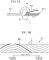
- the twist pitch of the inner fillings 40A twisted in the SZ manner is 3 meters or less.
- the twist pitch is the interval in the longitudinal direction between the reversal positions in the rotation direction (see FIG. 5B ).
- the twist pitch is a distance in the longitudinal direction from the position at which the winding direction of the inner filling 40A reverses from the S direction to the Z direction to the position at which the winding direction reverses from the Z direction to the S direction.
- the outer filling 40B is disposed so as not to be adjacent to the overlapping area 2a of the wrapping tube 2.
- the outer fillings 40B can be suppressed from entering the inside of the wrapping tube 2 from the overlapping area 2a.
- the outer filling 40B is disposed on the opposite side of the overlapping area 2a as viewed in the core 3 while being disposed not to be adjacent to the overlapping area 2a of the wrapping tube 2.
- the overlapping area 2a is disposed below the core 3 in FIG. 1
- the outer filling 40B is disposed above the core 3 in FIG. 1 .
- the outer filling 40B can be further suppressed from entering the inside of the wrapping tube 2 from the overlapping area 2a.
- FIG. 4 is an explanatory view of a manufacturing apparatus 70 of the optical fiber cable 100.
- the manufacturing apparatus 70 includes a supply source of each member, a core assembly machine 71, an extruder 72, a cooler 73, and a drum 74.
- the core assembly machine 71 is an apparatus that forms the core 3 by wrapping the optical fiber unit 10 and the inner filling 40A with the wrapping tube 2. Therefore, the core assembly machine 71 is supplied with the optical fiber unit 10 (for example, one or a plurality of intermittently-adhered optical fiber ribbons), the inner filling 40A, and the wrapping tube 2. In the present embodiment, the core assembly machine 71 assembles the optical fiber unit 10 and the inner filling 40A while twisting the optical fiber unit 10 and the inner filling 40A in the SZ manner (described later). Then, the core assembly machine 71 forms the core 3 by wrapping the optical fiber unit 10 and the inner filling 40A twisted in the SZ manner with the wrapping tube 2 and sends the core 3 to the extruder 72.
- the optical fiber unit 10 for example, one or a plurality of intermittently-adhered optical fiber ribbons
- the core assembly machine 71 assembles the optical fiber unit 10 and the inner filling 40A while twisting the optical fiber unit 10 and the inner filling 40A in
- the extruder 72 is an apparatus that extrudes the sheath 60.
- the core 3, the pair of tension members 20, the outer filling 40B, and the support wire 50 are supplied to the extruder 72.
- the optical fiber cable 100 in which the members are collectively covered with the sheath 60 is manufactured.
- the sheath 60 is extruded.
- the cooler 73 is a device that cools the sheath 60 of the optical fiber cable 100.
- the drum 74 is a member for winding the optical fiber cable 100.
- FIG. 5A is an explanatory view of a first twisting method of the optical fiber unit 10 and the inner filling 40A.
- the core assembly machine 71 has a rotary plate 6 (mesh plate) that swings and rotates (rotates in the SZ direction).
- the rotary plate 6 is formed in a circular plate shape.
- the rotary plate 6 has a plurality of unit holes 6a for inserting the optical fiber unit 10 (optical fiber ribbon) and an filling hole 6b for inserting the inner filling 40A.
- the unit holes 6a and the filling hole 6b are provided in one rotary plate 6, but the unit holes 6a and the filling hole 6b may be provided in separate rotary plates 6.
- the unit holes 6a and the filling hole 6b are provided in the separate rotary plates 6, in the first twisting method, the two rotary plates 6 swing and rotate in synchronization.
- the first twisting method is sometimes called "co-twisting" because the optical fiber unit 10 and the inner filling 40A are twisted together.
- FIG. 5B is an explanatory view (conceptual view) of the optical fiber unit 10 and the inner filling 40A twisted in the SZ manner by the first twisting method.
- FIG. 5B is a conceptual diagram for explaining the twisting method, and the scale of the drawing is not accurate (for example, the diameter of the optical fiber 1 is about 0.25 mm while the twist pitch in the drawing is 3 meters or less).
- the optical fiber unit 10 and the inner filling 40A are twisted together in the SZ manner. Therefore, the twist pitches (the interval in the longitudinal direction between the reversal positions in the rotation direction) of the optical fiber unit 10 and the inner filling 40A are substantially the same, and the reversal positions in the rotational direction are also substantially the same. In other words, the twisting phases of the optical fiber unit 10 and the inner filling 40A substantially match. Further, the twisting angles are substantially the same. Therefore, in the case of the first twist method (co-twisting), the inner filling 40A is disposed so as to be interposed between the optical fibers 1.
- the optical fiber 1 and the inner filling 40A can be twisted in an SZ manner by a simple method.
- the inner filling 40A is strongly constrained by the optical fiber 1.
- the constraint between the inner filling 40A and the optical fiber 1 is desirable for the constraint between the inner filling 40A and the optical fiber 1 to be weak. Therefore, in the twisting methods to be described below (second to fourth twisting methods), the optical fiber 1 and the inner filling 40A are each twisted in an SZ manner without being twisted together.
- FIG. 6A is an explanatory view of a second twisting method of the optical fiber unit 10 and the inner filling 40A.
- the core assembly machine 71 has two rotary plates 7A, 7B that swing and rotate (rotate in the SZ direction).
- the two rotary plates 7A, 7B include a unit rotary plate 7A for twisting the optical fiber unit 10 (optical fiber ribbon) and a filling rotary plate 7B for twisting the inner filling 40A.
- the unit rotary plate 7A and the filling rotary plate 7B are formed in a circular plate shape.
- a plurality of unit holes 7a for inserting the optical fiber unit 10 are formed in the unit rotary plate 7A.
- the filling rotary plate 7B has an filling hole 7b for inserting the inner filling 40A and a passage hole 7c for passing the optical fiber unit 10 which is twisted by the unit rotary plate 7A.
- the passage hole 7c is formed at the central portion of the filling rotary plate 7B.
- the filling hole 7b is located outside the passage hole 7c.
- the optical fiber unit 10 is twisted in the SZ manner. Since the cross section of each optical fiber 1 is circular, unevenness due to the outer shape of the optical fiber 1 is formed on the outer periphery of the optical fiber unit 10 configured by bundling a plurality of optical fibers 1. In other words, grooves (concave strips formed by gaps between the adjacent optical fibers 1 on the outer periphery of the optical fiber unit 10) are formed along the optical fibers 1 at the outer periphery of the twisted optical fiber unit 10 (the bundle of the optical fibers 1).
- the grooves formed on the outer periphery of the optical fiber unit 10 are also formed in the SZ manner. That is, on the outer periphery of the bundle of optical fibers 1, grooves between the adjacent optical fibers 1 are formed in the SZ manner.
- the filling rotary plate 7B swings and rotates on the downstream side of the unit rotary plate 7A, so that the inner filling 40A is twisted and disposed in an SZ manner in the outer periphery of the optical fiber unit 10 twisted in the SZ manner.
- the SZ-shaped twist of the inner filling 40A can be arbitrarily set with respect to the SZ-shaped twist of the optical fiber unit 10 without particular limitation.
- FIG. 6B is an explanatory view (conceptual view) of the optical fiber unit 10 and the inner filling 40A twisted in the SZ manner by the second twisting method.
- the inner filling 40A is disposed to cross the SZ-shaped grooves formed on the outer periphery of the twisted optical fiber unit 10 (bundle of the optical fibers 1). If at least one of the twist pitches, the reversal positions in the rotation direction, or the twist angles of the optical fiber unit 10 and the inner filling 40A is different, the inner filling 40A can be disposed to cross the SZ-shaped grooves. By disposing the inner filling 40A to cross the grooves, compared with the case where the inner filling 40A is interposed between the specific optical fibers 1 as shown in FIG. 5B , it is possible to suppress running of water in the gaps between the optical fibers 1.
- the inner filling 40A can be disposed to cross more grooves, and therefore it is possible to further suppress running of water in the gaps between the optical fibers 1.
- the rotary plates 6, 7B having the filling holes 6b, 7b are swung in order to twist the inner filling 40A in the SZ manner, so that the core assembly machine 71 will be enlarged. Therefore, in the twisting methods to be described below (third and fourth twisting methods), the inner filling 40A is twisted in the SZ manner without the inner filling 40A being moved largely by the rotary plate.
- FIG. 7A is an explanatory view of a third twisting method of the optical fiber unit 10 and the inner fillings 40A.
- the core assembly machine 71 has a unit rotary plate 7A that swings and rotates (rotates in the SZ direction) to twist the optical fiber unit 10 (optical fiber ribbon).
- the third twisting method unlike the first twisting method and the second twisting method, since the rotary plate for twisting the inner filling 40A is not provided, the configuration of the core assembly machine 71 can be simplified.
- the optical fiber unit 10 is twisted in the SZ manner. Since the cross section of each optical fiber 1 is circular, unevenness due to the outer shape of the optical fiber 1 is formed on the outer periphery of the optical fiber unit 10 configured by bundling a plurality of optical fibers 1. In other words, the above-described grooves are formed along the optical fiber 1 on the outer periphery of the twisted optical fiber unit 10 (the bundle of optical fibers 1). In the present embodiment, since the plurality of optical fibers 1 are twisted in the SZ manner, the grooves are also formed in the SZ manner.
- the inner filling 40A is longitudinally attached to the optical fiber unit 10 twisted in the SZ manner, on the downstream side of the unit rotary plate 7A.
- the inner filling 40A is attached to the outer periphery of the optical fiber unit 10 along the longitudinal direction.
- the inner filling 40A is guided to the inside of the grooves described above.
- the inner filling 40A is guided to the SZ-shaped grooves and displaced in the circumferential direction, and the inner filling 40A is twisted in the SZ manner on the outer periphery of the optical fiber unit 10 (see FIG. 7B ).
- the twist angle of the inner filling 40A is equal to the twist angle of the optical fiber unit 10.
- the inner filling 40A is usually thicker than the optical fiber 1, and the inner filling 40A is thicker than the width and depth of the grooves. Therefore, the inner filling 40A guided to the grooves may come out of the grooves while being attached to the outer periphery of the optical fiber unit 10. In such a case, the twist angle of the inner filling 40A is smaller than the twist angle of the optical fiber unit 10.
- the twist angle of the inner filling 40A is equal to or less than the twist angle of the optical fiber unit 10.
- the twist pitch and the reversal position in the rotation direction of the inner filling 40A may deviate from the twist pitch and the reversal position in the rotation direction of the optical fiber unit 10.
- FIG. 7B is an explanatory view (conceptual view) of the optical fiber unit 10 twisted in the SZ manner and the inner filling 40A by the third twisting method.
- the twist angle of the inner filling 40A is smaller than the twist angle of the optical fiber unit 10. Further, it is also possible to change the phase of the SZ-shaped twist of the inner filling 40A with respect to the SZ-shaped twist of the optical fiber unit 10 by adjusting the back tension of the inner filling 40A. Even in the third twisting method, at least one of the twist pitches, the reversal positions in the rotation direction, and the twist angles of the optical fiber unit 10 or the inner filling 40A can be made different. Therefore, the inner filling 40A can be disposed to cross the SZ-shaped grooves formed on the outer periphery of the optical fiber unit 10 (the bundle of optical fibers 1).
- FIG. 8 is an explanatory view (conceptual view) of a fourth twisting method of the optical fiber unit 10 and the inner filling 40A.
- the inner filling 40A is longitudinally attached to the optical fiber unit 10 twisted in the SZ manner.
- the inner filling 40A is attached along the longitudinal direction to the outer periphery of the optical fiber unit 10 twisted in the SZ manner. Therefore, the core assembly machine 71 does not have to be provided with a rotary plate for twisting the inner filling 40A.
- the twist is returned such that the twist angle of the optical fiber unit 10 becomes smaller (the twist angle is reduced).
- the inner filling 40A attached to the optical fiber unit 10 at the outer periphery of the optical fiber unit 10 is dragged back to untwist the optical fiber unit 10.
- the inner filling 40A is twisted in the SZ manner in the direction opposite to the SZ twist direction of the optical fiber unit 10.
- the twist pitches of the optical fiber unit 10 and the inner filling 40A are substantially the same as each other, and the reversal positions in the rotation direction are also substantially the same as each other, but the rotating directions at the reversal position are reversed.
- the phase of the SZ-shaped twist of the inner filling 40A with respect to the SZ-shaped twist of the optical fiber unit 10 is shifted by 180 degrees. Therefore, in the case of the fourth twisting method, since the inner filling 40A can be disposed to cross more grooves, it is possible to further suppress running of water in the gaps of the optical fibers 1.
- the optical fiber cable 100 includes a core 3 including a plurality of optical fibers 1, an inner filling 40A, and a wrapping tube 2 which wraps the plurality of optical fibers 1 and the inner filling 40A, an outer filling 40B disposed outside the core 3, and a sheath 60 that covers the core 3 and the outer filling 40B.
- a core 3 including a plurality of optical fibers 1, an inner filling 40A, and a wrapping tube 2 which wraps the plurality of optical fibers 1 and the inner filling 40A, an outer filling 40B disposed outside the core 3, and a sheath 60 that covers the core 3 and the outer filling 40B.
- the outer filling 40B and the inner filling 40A have water absorbency. Thereby, the running water inside and outside the core 3 can be prevented more reliably.
- the inner filling 40A is disposed such that the position in the core 3 changes in the longitudinal direction. Thereby, as compared with the case where the position of the inner filling 40A in the core 3 does not change, it is possible to suppress the deviation of the waterproof performance in the core 3.
- the outer filling 40 B is longitudinally attached to the core 3.
- the sheath 60 can be easily extruded, and the optical fiber cable 100 can be manufactured more stably.
- the position of the inner filling 40A in the core 3 changes in the longitudinal direction
- the outer filling 40B is longitudinally attached to the core 3.
- the relative positions of the inner filling 40A and the outer filling 40B change in the longitudinal direction of the optical fiber cable 100. Therefore, the inner filling 40A and the outer filling 40B can be prevented from being unevenly disposed in the optical fiber cable 100, and local deterioration in waterproof performance can be suppressed.
- the inner filling 40A may be disposed by the second to fourth twisting methods so as to cross these grooves.
- This effect can also be obtained in a case where the plurality of optical fibers 1 are twisted in one direction (helically). That is, by disposing the inner filling 40A so as to cross the grooves between the adjacent optical fibers 1, formed on the outer periphery of the bundle of the plurality of optical fibers 1 twisted together, regardless of the twisted state of the optical fibers 1, waterproof performance can be enhanced.
- the wrapping tube 2 is wound so as to have an overlapping area 2a in which both edges of the wrapping tube 2 overlap, and the outer filling 40B is disposed at a position not adjacent to the overlapping area 2a.
- the outer filling 40B can be suppressed from entering from the overlapping area 2a to the inside of the wrapping tube 2.
- a method of manufacturing an optical fiber cable according to the present embodiment includes forming a core 3 by wrapping a plurality of optical fibers 1 and an inner filling 40A with a wrapping tube; and forming a sheath 60 that covers the core 3 and an outer filling 40B, in a state where the outer filling 40B is attached to the outside of the core 3. According to the manufacturing method, it is possible to manufacture an optical fiber cable 100 having stable waterproof performance, including the inner filling 40A and the outer filling 40B.
- FIG. 9 is a transverse cross-sectional view of an optical fiber cable 100 according to a second embodiment.
- the same members as in the first embodiment are denoted by the same reference numerals, and description thereof is omitted.
- the main body portion having the core 3 is formed in a rectangular shape (square shape), and the support wire portion having the support wire 50 is formed in a circular shape in the transverse cross-sectional view.
- the longitudinal direction (X direction) is the direction in which the optical fiber cable 100 extends.
- a long-side direction (width direction or Y direction) is a direction in which the pair of tension members 20 are arranged.
- a short-side direction (thickness direction or Z direction) is a direction in which the pair of separators 30 are arranged, and is orthogonal to both the longitudinal direction and the long-side direction.
- the long-side direction is a direction along the long side in the cross section of the optical fiber cable 100 (main body portion).
- the short-side direction is a direction along the short side in the cross section of the optical fiber cable 100 (main body portion).
- the optical fiber cable 100 includes a core 3 having an optical fiber unit 10, a pair of tension members 20, and a sheath 60. Further, the optical fiber cable 100 of the second embodiment includes a pair of separators 30. Even in the second embodiment, the optical fiber cable 100 has an inner filling 40A and an outer filling 40B.
- the optical fiber unit 10 is configured with a plurality of intermittently-adhered optical fiber ribbons (intermittently-fixed optical fiber ribbons).
- the optical fiber unit 10 of the second embodiment is configured with one intermittently-adhered optical fiber ribbon.
- the configuration of the optical fiber unit 10 may be changed as appropriate.
- the optical fiber unit 10 may be configured with a plurality of optical fiber ribbons, or may be configured by bundling a plurality of single optical fibers 1.
- a 12-fiber optical fiber cable 100 is configured instead of the 24-fiber optical fiber cable which is generally used.
- the inner filling 40A has a role of securing the volume of the accommodation space in the first covering portion 60A.
- the inner filling 40A is a water absorbing yarn. This makes it possible to suppress running of water on the inside of the core 3 (the inside of the wrapping tube 2).
- the separators 30 are members for facilitating the separation operation of the sheath 60.
- the separators 30 are tape-shaped (flat-shaped and strip-shaped) members, and are disposed between the core 3 (the wrapping tube 2) and the sheath 60 along the longitudinal direction.
- the thickness of the separators 30 is, for example, about 0.2 mm.
- the separators 30 are not fused or adhered to the sheath 60, and are formed of a material that easily peels off from the sheath 60.
- the tape-shaped separators 30 are disposed such that the tape surfaces are parallel to the width direction.
- the pair of separators 30 are disposed side by side in the thickness direction.
- the core 3 is disposed between the pair of separators 30.
- the outer filling 40B is disposed between the pair of separators 30. Further, as in the first embodiment, a structure in which the separators 30 are not provided may be adopted.
- the sheath 60 of the second embodiment covers the periphery of the core 3, the pair of tension members 20, the pair of separators 30, the outer filling 40B, the support wire 50 and the like.
- the first covering portion 60A covers the periphery of the core 3, the pair of tension members 20, the pair of separators 30, and the outer filling 40B.
- the first covering portion 60A has a substantially rectangular outer shape in a cross section.
- a plurality of notches 60N are formed on the outer surface of the first covering portion 60A.
- a pair of the notches 60N are provided on each of the upper and lower surfaces, but the notches 60N may be formed one by one on the upper and lower surfaces. Further, as in the first embodiment, the notches 60N may not be present. It is desirable for the set temperature for extrusion molding of the sheath 60 to be lower than the melting points of the separator 30 and the wrapping tube 2.
- the outer filling 40B is longitudinally attached to the outside of the core 3, and the inner filling 40Ais twisted and disposed in an SZ manner inside the core 3.
- the position of the inner filling 40A relative to the core 3 changes in the longitudinal direction. Accordingly, the inner filling 40A and the outer filling 40B can be suppressed from being unevenly disposed inside the optical fiber cable 100 and local deterioration of the waterproof property can be suppressed.
- the optical fiber unit 10 is not tightened by the inner filling 40A, and thus an increase in the transmission loss of the optical fiber 1 can be suppressed.
- the outer filling 40B is disposed so as not to be adjacent to the overlapping area 2a of the wrapping tube 2.
- the outer filling 40B can be suppressed from entering the inside of the wrapping tube 2 from the overlapping area 2a.
- the outer filling 40B is disposed so as not to be adjacent to the overlapping area 2a of the wrapping tube 2, and is disposed so as to be closer to the outside edge of the press winding 2 which is the outside of the overlapping area 2a.
- the outer filling 40B is disposed closer to the left side (the support wire 50 side) of FIG. 9 viewed from the overlapping area 2a so as to be closer to the edge of the wrapping tube 2 which is the outside (lower side in FIG. 9 ) of the overlapping area 2a.
- the outer filling 40B can be further suppressed from entering the inside of the wrapping tube 2 from the overlapping area 2a.
- FIG. 10 is an explanatory view of a manufacturing apparatus 70 of the optical fiber cable 100 according to the second embodiment.
- the manufacturing apparatus 70 includes a supply source of each member, a core assembly machine 71, an extruder 72, a cooler 73, and a drum 74.
- the core assembly machine 71 twists and arranges the inner filling 40A in the SZ manner inside the core 3.
- the method of the core assembly machine 71 twisting the inner filling 40A in the SZ manner may be any of the first to fourth twisting methods described above or any other method.
- the core 3, the pair of tension members 20, the outer filling 40B, and the support wire 50 are supplied to the extruder 72 as in the first embodiment, and in the second embodiment, the pair of separators 30 are also supplied.
- the optical fiber cable 100 in which the members are collectively covered with the sheath 60 is manufactured.
- the optical fiber cable 100 includes the core 3 having the optical fiber unit 10, the outer filling 40B, the pair of tension members 20, the pair of separators 30, the support wire 50, and the sheath 60.
- the X direction is the direction in which the optical fiber cable 100 extends.
- the Y direction is a direction in which the pair of tension members 20 face each other.
- the Z direction is a direction orthogonal to both the X direction and the Y direction.
- the X direction is referred to as the longitudinal direction
- the Y direction is referred to as the width direction
- the Z direction is referred to as the thickness direction.
- the cross-section perpendicular to the longitudinal direction is referred to as a transverse cross-section.
- the optical fiber unit 10 of the present embodiment is a so-called intermittently-fixed optical fiber ribbon, and is formed by intermittently connecting a plurality of optical fibers 1 by the connecting portions 11. More specifically, the plurality of optical fibers 1 are arranged in parallel, and adjacent optical fibers 1 are connected by the connecting portions 11.
- the connecting portions 11 are disposed at regular intervals in the longitudinal direction.
- the connecting portions 11 connecting the adjacent optical fibers 1 which are adjacent to each other 1 in the vicinity of the adjacent optical fibers 1 are disposed at positions shifted in the longitudinal direction, with respect to the positions of the connecting portions 11 connecting the adjacent optical fibers 1. In this manner, the connecting portions 11 are disposed in a staggered manner with respect to both directions of the longitudinal direction and the width direction orthogonal to the longitudinal direction.
- the connecting portions 11 are formed of, for example, a UV curable resin or the like, and are bonded to the optical fibers 1 adjacent to each other to connect the optical fibers 1 with each other.
- the connection state can be released by separating the connecting portions 11 from the optical fibers 1 by the force of the fingers.
- the configuration of the optical fiber unit 10 is not limited to the intermittently-fixed optical fiber ribbon, but may be, for example, a configuration in which a plurality of optical fibers 1 are bundled with a binding material or the like.
- an optical fiber strand or an optical fiber core wire can be used as the optical fibers 1.
- the primary layer or secondary layer covering the bare fiber of the optical fibers 1 is preferably formed of a UV curable resin.
- the secondary layer itself may be colored, or a colored layer may be further provided on the outer periphery of the secondary layer. Alternatively, an identification marking may be provided on the outer periphery of the optical fibers 1.
- the core 3 is formed by wrapping the optical fiber unit 10 and the inner filling 40A by the wrapping tube 2.
- the inner filling 40A is disposed inside the wrapping tube 2.
- a plastic tape member or the like can be used as the wrapping tube 2.
- PET polyethylene terephthalate
- PET polyethylene terephthalate
- the inner filling 40A it is desirable to use a yarn whose fineness can be freely selected or changed.
- a material for forming the inner filling 40A for example, polypropylene (PP), polyester (PEs) or the like can be used.
- a yarn made of PP is used as the inner filling 40A.
- the material of the inner filling 40A is not limited to PP yarns, and some or all of the inner filling 40A may be replaced with water absorbing yarns and the like.
- the optical fiber unit 10 and the inner filling 40A are wrapped by the wrapping tube 2 while twisted together in the SZ manner.
- the tension and the side pressure applied to the optical fiber 1 can be suppressed, and the intermediate post-branching operation or the like can be easily performed.
- optical fiber unit 10 and the inner filling 40A may be twisted in a spiral.
- the outer filling 40B is disposed in the gap between the wrapping tube 2 and the sheath 60, that is, on the outside of the core 3.
- the outer filling 40B can be formed using a PP yarn or the like, similar to the inner filling 40A.
- the inner filling 40A and the outer filling 40B secures the volume of an accommodation space that will be described later.
- the inner filling 40A resists the pressure of the resin that forms the sheath 60, thereby making it possible to prevent the accommodation space from being narrowed excessively.
- the upper limit and lower limit of the cross-sectional area of the accommodation space are set, and the amount of the inner filling 40A may be adjusted such that the cross-sectional area of the accommodation space is in the range of the upper limit and the lower limit.
- the pair of tension members 20 are disposed so as to sandwich the core 3 and the outer filling 40B in the width direction.
- steel wire, metal fiber, aramid fiber, glass fiber, carbon fiber, fiber reinforced plastic (FRP), or the like can be used.
- the tension members 20 function to resist the tension applied to the optical fibers 1 in the longitudinal direction, and suppress the application of the tension to the optical fibers 1.
- the pair of separators 30 are disposed so as to sandwich the core 3 and the outer filling 40B in the thickness direction.
- the separators 30 are each formed in a plate shape extending in the width direction in a transverse cross-sectional view, and are disposed substantially in parallel with each other.
- the sheath 60 partially enters between the pair of separators 30 from both sides in the width direction.
- the pair of separators 30 and the sheath 60 between the pair of separators form a substantially rectangular accommodation space in a transverse cross-sectional view.
- the core 3 and the outer filling 40B are disposed in the substantially rectangular accommodation space.
- a sheet material such as polypropylene, polyamide, or polyimide can be used.
- the separators 30 are preferably formed of a material having a melting point higher than the melting point of the sheath 60 in order to prevent fusion with the sheath 60 at the time of extrusion molding of the sheath 60.
- the support wire 50 is formed of a steel wire or the like.
- the outer diameter of the support wire 50 is larger than the outer diameter of the tension members 20.
- the support wire 50 and the pair of tension members 20 are disposed side by side in the width direction.
- the support wire 50 is used as a suspension line for the overhead installation of the optical fiber cable 100.
- the optical fiber cable 100 may not have the support wire 50.
- the sheath 60 has a first covering portion 60A, a second covering portion 60B, and a connecting portion 60C connecting the first covering portion 60A and the second covering portion 60B to each other.
- the first covering portion 60A integrally covers the core 3, the outer filling 40B, the pair of separators 30, and the pair of tension members 20.
- the second covering portion 60B covers the support wire 50.
- the first covering portion 60A is formed in a substantially rectangular shape in a transverse cross-sectional view.
- a notch 60N is formed in a portion covering the separator 30 in the first covering portion 60A.
- the notch 60N is formed in a V-shape in a transverse cross-sectional view, and the width gradually decreases toward the separator 30.
- a pair of notches 60N are formed in each of the upper end surface and the lower end surface of the first covering portion 60A.
- a cutting blade or the like is brought into contact with each notch 60N, and cuts the first covering portion 60A covering the separator 30. Thereby, the first covering portion 60A can be divided and the core 3 can be easily taken out.
- polyolefin (PO) resin such as polyethylene (PE), polypropylene (PP), ethylene ethyl acrylate copolymer (EEA), ethylene vinyl acetate copolymer (EVA), and ethylene propylene copolymer (EP), polyvinyl chloride
- PE polyethylene
- PP polypropylene
- EOA ethylene ethyl acrylate copolymer
- EVA ethylene vinyl acetate copolymer
- EP ethylene propylene copolymer
- the sheath 60 can be formed by extrusion molding or the like. Even in this case, since the optical fiber unit 10 is wrapped by the wrapping tube 2, the sheath 60 flowing at high temperature can be suppressed from entering the gap between the optical fibers 1. It is desirable for the set temperature at the time of extrusion molding of the sheath 60 to be lower than the melting point of the separator 30 or the wrapping tube 2 such that the separator 30 and the wrapping tube 2 are not fused with the sheath 60.
- the optical fiber cable 100 of the present example has a configuration in which four-fiber intermittently-fixed optical fiber ribbons are used as the optical fiber unit 10, and six intermittently-fixed optical fiber ribbon s are wrapped by the wrapping tube 2.
- As the inner filling 40A one 1670 dtex PEs water absorbing yarn is used.
- As the outer filling 40B one 1670 dtex PEs water absorbing yarn is used.
- a tape made of PET with a thickness of 0.25 mm is used as the wrapping tube 2.
- the thickness in the thickness direction of the first covering portion 60A is about 3.5 mm, and the width in the width direction is about 5.5 mm.
- the installation density of the optical fiber 1 in the accommodation space formed by the pair of separators 30 and the sheath 60 between the separators 30 is in the range of 8.5 to 10.9 fibers/mm 2 .
- the installation density of the optical fiber is a numerical value defined by the following Expression (1).
- d is the installation density of the optical fiber
- N is the number of fibers of the optical fiber
- S is the sectional area of the accommodation space
- P is the sum of the cross-sectional areas of each member accommodated in the accommodation space (inner filling 40A, outer filling 40B, and wrapping tube 2).
- d N ⁇ S ⁇ P
- the installation density d of the optical fiber 1 in a predetermined range, the following advantages can be obtained. That is, when the installation density d of the optical fiber 1 is significantly small, the possibility of the optical fiber 1 moving in the accommodation space increases. Further, the running water length at the time of the waterproof test becomes long, and the possibility of failing the waterproof test increases. On the other hand, if the installation density d of the optical fiber 1 is significantly large, transmission loss may increase.
- the above-described numerical range of the installation density d is suitable as an index for making the optical fiber cable 100 have desired performance in a case where, for example, the amount of the inner filling 40A and the outer filling 40B are fixed.
- the installation density d described above does not limit the present invention, and the optical fiber cable 100 may be defined by an index other than the installation density d according to the type, shape, application, or the like of the optical fiber cable 100.
- the core 3 is formed by SZ twisting the optical fiber unit 10 and the inner filling 40A and wrapping them with the wrapping tube 2. Further, while the core 3 is formed, the outer filling 40B and the like are longitudinally attached to the core 3, and the first covering portion 60A is extruded around the respective members.
- the excess length ratio is in the range of 99.85% to 100.2%.
- the excess length ratio refers to the ratio of the length of the non-tensioned outer filling 40B to the length of the sheath 60 in the longitudinal direction. The length of the non-tensioned outer filling 40B is measured by taking the outer filling 40B out of the sheath 60.
- Table 1 below shows the results of checking the transmission loss and the waterproof performance of the plurality of optical fiber cables 100 having different excess length ratios as described above.
- the transmission loss at a wavelength of 1550 nm is measured by an OTDR (optical time domain reflectometer).
- Table 1 below the maximum value of the transmission loss of the 24 optical fibers 1 included in each optical fiber cable 100 is described.
- Example 1 Comparative Example 1 Comparative Example 2 Excess length ratio 99.95% 100% 100.1 % 100.2% 99.85% - Transmission loss 0.23 dB/km 0.21 dB/km 0.20 dB/km 0.21 dB/km 0.28 dB/km 0.20 dB/km Running water length ⁇ 3 m ⁇ 3 m ⁇ 3 m ⁇ 3 m ⁇ 3 m fail
- the transmission loss is 0.25 dB/km or less and the running water length is 3 meters or less, and good results are obtained.
- the tension applied to the outer filling 40B is significantly low when the outer filling 40B is covered with the first covering portion 60A, so it is difficult to stably manufacture the optical fiber cable 100.
- the extra length ratio it is more preferable for the extra length ratio to be 100.2% or less.
- the optical fiber cable 100A of Comparative Example 2 as shown in FIG. 13 is manufactured and its performance is checked.
- the optical fiber cable 100A of Comparative Example 2 does not have the inner filling 40A, and the fillings of the combined amount of the inner filling 40A and the outer filling 40B in Example 1 are disposed as the outer filling 40C. That is, the optical fiber cable 100A of Comparative Example 2 has the same configuration as the optical fiber cable 100 of Example 1 except that the inner filling 40A of Example 1 is disposed outside the core 3.
- the outer filling 40C causes the wrapping tube 2 to be largely recessed toward the inside of the core 3.
- the core 3 is greatly deformed in this manner, when the optical fiber unit 10 is twisted together inside the core 3, the optical fiber unit 10 may be caught on the depressed portion of the wrapping tube 2 and may not be properly twisted.
- the twisting is easily inhibited by deformation of the core 3.
- the fillings 40A and 40B are separately disposed on both the inside and the outside of the core 3, thereby reducing the deformation of the core 3. Therefore, the occurrence of inconveniences such as the optical fiber unit 10 not being properly twisted can be suppressed.
- the fillings 40A and 40B are disposed on both the inside and the outside of the core 3, so that running of water in both the inside and the outside of the core 3 is prevented, and waterproof performance can be secured.
- the deformation of the core 3 caused by the outer filling pressing the core 3 can be reduced.
- the transmission loss of the optical fiber 1 can be suppressed to a small amount by making the excess length ratio of the outer filling 40B into 99.95% or more.
- the optical fiber cable 100 can be manufactured more stably.
- Example 1 4-fiber intermittently-fixed optical fiber ribbons are used as the optical fiber unit 10 and the total number of fibers included in the core 3 is 24 fibers, but the number of fibers of the optical fiber unit 10 and the total number of fibers included in the core 3 can be changed as appropriate.
- the installation density is 6.5 to 13.5 fibers/mm 2 in the case of 8 fibers, and 6.8 to 10.6 fibers/mm 2 in the case of 12 fibers.
- the size of the first covering portion 60A is made larger than that of Example 1 and a 48-fiber core 3 is used, the installation density is 7.5 to 9.0 fibers/mm 2 .
Abstract
Description
- The present invention relates to an optical fiber cable.
- Priority is claimed on
Japanese Patent Application No. 2017-109872 filed in Japan on June 02, 2017 Japanese Patent Application No. 2018-039696 filed in Japan on March 06, 2018 - In the related art, optical fiber cables as disclosed in
JP 2014-219494 A JP 2014-139609 A -
EP 0 286 349 A2 discloses an optical fiber cable that includes optical fiber units, a tubular member, an absorbing tape, a corrugated metallic shield and a plastic jacket. A water blocking material is disposed in the inner space of the tubular member to fill the core. -
US 2003/049002 A1 concerns an optical fiber cable that includes optical fibers, a filling material, a central plastic tube, a water blocking tape and an outer sheath. The filling material is typically a jelly-like material that has a viscosity sufficiently low to be easily introduced into the buffer tubes during the manufacturing process and to allow a substantially free relative movement of the fibers, but sufficiently high in order to oppose a sufficient physical barrier against the longitudinal flow of water. -
JP 2017 049510 A - In this type of optical fiber cable, a core may be formed by wrapping a plurality of optical fibers and a filling with a press winding tape (also referred to simply as a wrapping tube), and the core may be accommodated in a sheath. Further, the use of filling having water absorbency may prevent water from running in the optical fiber cable.
- However, in a case where such a core is formed, it has been found that the desired waterproof performance may not be obtained depending on the position and state of the filling.
- An object of the present invention is to provide an optical fiber cable having stable waterproof performance.
- In order to solve the above problems, an optical fiber cable according to a first aspect of the present invention includes a core including a plurality of optical fibers, an inner filling, and a wrapping tube which wraps the plurality of optical fibers and the inner filling; an outer filling that is disposed outside the core; and a sheath that covers the core and the outer filling, wherein the plurality of optical fibers are twisted together,
Wherein grooves between adjacent optical fibers are formed on an outer periphery of a bundle of the plurality of optical fibers, and wherein the inner filling is disposed to cross the grooves. - According to the above aspects of the present invention, it is possible to provide an optical fiber cable having stable waterproof performance due to an outer filling and an inner filling.
-
-
FIG. 1 is a transverse cross-sectional view of an optical fiber cable according to a first embodiment. -
FIG. 2A is an explanatory view of an intermittently-adhered optical fiber ribbon. -
FIG. 2B is an explanatory view of the intermittently-adhered optical fiber ribbon. -
FIG. 3A is an explanatory view of another intermittently-adhered optical fiber ribbon. -
FIG. 3B is an explanatory view of the other intermittently-adhered optical fiber ribbon. -
FIG. 4 is an explanatory view of a method of manufacturing an optical fiber cable. -
FIG. 5A is an explanatory view of a first twisting method of an optical fiber unit and an inner filling. -
FIG. 5B is an explanatory view (conceptual view) of the optical fiber unit and the inner filling twisted in an SZ manner by the first twisting method. -
FIG. 6A is an explanatory view of a second twisting method of the optical fiber unit and the inner filling. -
FIG. 6B is an explanatory view (conceptual view) of the optical fiber unit and the inner filling twisted in the SZ manner by a second twisting method. -
FIG. 7A is an explanatory view of a third twisting method of the optical fiber unit and the inner filling. -
FIG. 7B is an explanatory view of the optical fiber unit and the inner filling twisted in the SZ manner by the third twisting method. -
FIG. 8 is an explanatory view (conceptual view) of a fourth twisting method of the optical fiber unit and the inner filling. -
FIG. 9 is a cross-sectional view of an optical fiber cable according to a second embodiment. -
FIG. 10 is an explanatory view of an apparatus for manufacturing the optical fiber cable according to the second embodiment. -
FIG. 11 is a transverse cross-sectional view of an optical fiber cable according to a third embodiment. -
FIG. 12 is an explanatory view of an optical fiber unit ofFIG. 11 . -
FIG. 13 is a transverse cross-sectional view of an optical fiber cable of a comparative example. - At least the following matters will be clear from the description of the specification and drawings to be described below. It is clear that an optical fiber cable includes a core including a plurality of optical fibers, an inner filling, and a wrapping tube which wraps the plurality of optical fibers and the inner filling; an outer filling that is disposed outside the core; a pair of tension members disposed so as to sandwich the core; and a sheath that covers the core, the outer filling, and the pair of tension members, in which the outer filling is longitudinally attached to the outside of the core, and the inner filling is twisted and disposed in an SZ manner inside the core. Thus, the fillings can be prevented from being unevenly disposed in the optical fiber cable, and local deterioration of the waterproof property can be suppressed.
- It is desirable for the wrapping tube to be wound so as to have an overlapping area of both edges of the wrapping tube, and for the outer filling to be disposed at a position not adjacent to the overlapping area of the wrapping tube. Thus, the outer filling can be suppressed from entering the inside of the wrapping tube from the overlapping area of the wrapping tube.
- It is desirable for the outer filling to be disposed on the opposite side of the overlapping area of the wrapping tube as viewed from the core. Thus, the outer filling can be further suppressed from entering the inside of the wrapping tube from the overlapping area of the wrapping tube.
- It is desirable for the outer filling to be disposed closer to the outside edge of the wrapping tube which is outside of the overlapping area. Thus, the outer filling can be further suppressed from entering the inside of the wrapping tube from the overlapping area of the wrapping tube.
- It is desirable for the plurality of optical fibers to be twisted and arranged in the SZ manner. Thus, the transmission loss of the optical fiber can be suppressed.
- It is desirable for the inner filling to be twisted in the SZ manner together with the plurality of optical fibers. Thus, both the inner filling and the plurality of optical fibers can be twisted in the SZ manner.
- It is desirable for the inner filling to be disposed so as to cross SZ-shaped gaps of the optical fibers. Thus, the running of water in the gaps of the optical fibers can be suppressed.
- It is desirable for the phase of the SZ-shaped twist of the inner filling to be shifted by 180 degrees with respect to the SZ-shaped twist of the optical fiber. Thus, the running of water in the gaps of the optical fibers can be further suppressed.
- A method of manufacturing an optical fiber cable in which a core is formed by wrapping a plurality of optical fibers twisted in an SZ manner and an inner filling with a wrapping tube, and an outer filling longitudinally attached to the outside of the core and a pair of tension members arranged so as to sandwich the core are collectively covered with a sheath is provided. Thus, the fillings can be prevented from being unevenly disposed in the optical fiber cable, and local deterioration of the waterproof property can be suppressed.
- It is desirable for the plurality of optical fibers and the inner filling to be twisted together in an SZ manner. Thus, both the inner filling and the plurality of optical fibers can be twisted in the SZ manner by a simple method.
- It is desirable for the plurality of optical fibers and the inner filling to be twisted separately in an SZ manner. Thus, the twist of the inner filling can be arbitrarily set with respect to the twist of the optical fiber.
- It is desirable for the inner filling to be twisted in the SZ manner by attaching the inner filling along the longitudinal direction to the outer periphery of the plurality of optical fibers twisted in the SZ manner. Thus, the inner filling can be twisted in the SZ manner by a simple method.
- It is desirable for the inner filling to be twisted in an SZ manner in the direction opposite to the twisting direction of the plurality of optical fibers by attaching the inner filling along the longitudinal direction to the outer peripheries of the plurality of optical fibers twisted in the SZ manner, and untwisting the plurality of optical fibers.
- Thus, the phase of the SZ-shaped twist of the inner filling can be shifted by 180 degrees with respect to the SZ-shaped twist of the optical fiber, and running of water in the gaps of the optical fibers can be suppressed.
-
FIG. 1 is a cross-sectional view (hereinafter simply referred to as "transverse cross-sectional view") orthogonal to the longitudinal direction of theoptical fiber cable 100 of the first embodiment. Hereinafter, the longitudinal direction of theoptical fiber cable 100 is simply referred to as the longitudinal direction, and is represented by the X axis. - The
optical fiber cable 100 includes a main body portion having acore 3 and a support wire portion having asupport wire 50. The main body portion and the support wire portion are each formed in a substantially circular shape in a transverse cross-sectional view. The outer diameter of the main body portion is larger than the outer diameter of the support wire portion. - The support wire portion is configured by covering the
support wire 50 made of a steel wire or the like with a sheath 60 (second coveringportion 60B). The support wire portion and the main body portion are connected by the sheath 60 (connectingportion 60C). By cutting the connectingportion 60C, the main body portion and the support wire portion can be separated. In the present specification, both of the optical fiber cable with the supporting wire and the optical fiber cable only including the main body portion without the support wire portion are simply referred to as the "optical fiber cable 100". - The
optical fiber cable 100 includes acore 3 having anoptical fiber unit 10, a pair oftension members 20, and asheath 60. In addition, theoptical fiber cable 100 of the present embodiment includes aninner filling 40A and anouter filling 40B. - The
optical fiber unit 10 is configured with a plurality of optical fibers 1 (optical fiber core wires). Here, theoptical fiber unit 10 is configured with a plurality of intermittently-adhered optical fiber ribbons (intermittently-fixed optical fiber ribbons). -
FIGS. 2A and 2B are explanatory views of an intermittently-adhered optical fiber ribbon. The intermittently-adhered optical fiber ribbon is an optical fiber ribbon in which a plurality ofoptical fibers 1 are arranged in parallel with each other, and are intermittently connected. In the following description, the direction in which the plurality ofoptical fibers 1 are arranged in parallel is referred to as the ribbon width direction. - Two adjacent
optical fibers 1 are connected by a connectingportion 11. A plurality of connectingportions 11 which connect two adjacentoptical fibers 1 are intermittently disposed in the longitudinal direction. Further, the plurality of connectingportions 11 of the optical fiber ribbon are intermittently disposed two-dimensionally in the longitudinal direction and the ribbon width direction. The connectingportions 11 are formed by applying an ultraviolet curing resin as an adhesive to theoptical fibers 1 arranged in parallel and then irradiating and solidifying the fibers with ultraviolet rays. In addition, the connectingportions 11 may be made of a thermoplastic resin. - A region other than the connecting
portion 11 between two adjacentoptical fibers 1 is a non-connecting portion 12 (separation portion). In thenon-connecting portion 12, two adjacentoptical fibers 1 are not connected. The connectingportions 11 and thenon-connecting portions 12 are alternately arranged in the ribbon width direction. Thus, the optical fiber ribbon can be spread in a mesh shape as shown inFig. 2B by applying force to the ribbon so that it spreads in the width direction of the ribbon. Further, the optical fiber ribbon can be rolled into a bundle, and a large number ofoptical fibers 1 can be accommodated at a high density. In thenon-connecting portion 12, two adjacentoptical fibers 1 may be in contact with or separated from each other. -
FIGS. 3A and 3B are explanatory views of another intermittently-adhered optical fiber ribbon. The intermittently-adhered optical fiber ribbon includes a plurality of (here, four) pairs of optical fibers 1 (fiber pairs) connected along the longitudinal direction. Adjacent fiber pairs are intermittently connected by the connectingportions 11. Also, in this intermittently-adhered optical fiber ribbon, the connectingportions 11 and thenon-connecting portions 12 are alternately arranged in the ribbon width direction. Through this, it is possible to spread the optical fiber ribbon in a mesh shape, or to roll the fiber pairs into a bundle. - The configuration of the intermittently-adhered optical fiber ribbon is not limited to that shown in drawings. For example, the arrangement of the connecting
portions 11 may be changed, or the number ofoptical fibers 1 may be changed. Further, the configuration of theoptical fiber unit 10 may be changed as appropriate. For example, theoptical fiber unit 10 may be configured by bundling a plurality of singleoptical fibers 1. - As shown in
FIG. 1 , thecore 3 includes theoptical fiber unit 10 and a wrapping tube 2 (press winding tape). Specifically, thecore 3 is formed by wrapping theoptical fiber unit 10 with the wrappingtube 2. In the present embodiment, thecore 3 further has aninner filling 40A. Theinner filling 40A is disposed inside the wrappingtube 2. - The wrapping
tube 2 is a member that wraps theoptical fiber unit 10. By wrapping theoptical fiber unit 10 with the wrappingtube 2, theoptical fiber 1 can be prevented from being buried in (biting into the inside of) thesheath 60 when the sheath is formed 60 with a molten resin. The wrappingtube 2 is made of, for example, a plastic tape member. For example, polyethylene terephthalate (PET) can be used as a material of the wrappingtube 2. In the present embodiment, in the cross section of theoptical fiber cable 100, the wrappingtube 2 is wound in a spiral shape, and the overlappingarea 2a (seeFIG. 1 ) is formed by overlapping the two edges of the wrappingtube 2. - The
inner filling 40A is a filling disposed inside the wrappingtube 2. Theinner filling 40A has a role of securing the volume of the space (accommodation space) in thefirst covering portion 60A of thesheath 60. That is, when thesheath 60 is extruded, theinner filling 40A resists the pressure of the resin that forms thesheath 60, thereby making it possible to prevent the accommodation space from being narrowed excessively. In addition, in order to form the accommodation space appropriately, the upper limit and lower limit of the cross-sectional area of the accommodation space are set, and the amount of theinner filling 40A may be adjusted such that the cross-sectional area of the accommodation space is in the range of the upper limit and the lower limit. - In the present embodiment, the
inner filling 40A is a water absorbing yarn. Since the inner filling 40A has water absorbency as described above, it is possible to suppress running of water on the inside of the core 3 (inside of the wrapping tube 2).
As theinner filling 40A, it is desirable to use a yarn whose fineness can be freely selected or changed. - The
tension member 20 is a member that resists the contraction of thesheath 60 and suppresses strain, distortion or bending applied to the optical fiber unit 10 (particularly, the optical fiber 1). Thetension member 20 is a linear member and is embedded in the inside of thesheath 60. As a material of thetension member 20, non-metallic materials or metallic materials can be used. As non-metallic materials, for example, glass fiber reinforced plastics (GFRP), aramid fiber reinforced plastics (KFRP) reinforced with Kevlar (registered trademark), and fiber reinforced plastics (FRP) such as polyethylene fiber reinforced plastics reinforced with polyethylene fibers can be used. As the metallic material, metal wires such as steel wires can be used. Although the cross-sectional shape of thetension member 20 is circular inFIG. 1 , the cross-sectional shape may be flat, elliptical, rectangular, or square, for example. Thetension members 20 are disposed in parallel in the longitudinal direction. Thecore 3 is disposed between the pair oftension members 20. - The
outer filling 40B is a filling disposed between the wrappingtube 2 and the sheath 60 (first coveringportion 60A). That is, theouter filling 40B is a filling disposed outside the wrappingtube 2. Theouter filling 40B has a role of filling the gap between the wrappingtube 2 and thesheath 60. In the present embodiment, theouter filling 40B is a water absorbing yarn. Since the outer filling 40B has water absorbency as described above, it is possible to suppress running of water in the gap between the wrappingtube 2 and thesheath 60. - The
sheath 60 is a member that covers other components to be accommodated.
Thesheath 60 covers the periphery of thecore 3, the pair oftension members 20, theouter fillings 40B, thesupport wire 50 and the like all together. Thesheath 60 has afirst covering portion 60A, asecond covering portion 60B, and a connectingportion 60C. - The
first covering portion 60A is a portion for collectively covering the periphery of thecore 3, the pair oftension members 20, and the outer filling 40B. Thefirst covering portion 60A is formed in a substantially cylindrical shape. The outer shape in the cross section of thefirst covering portion 60A is circular. - The
second covering portion 60B is a portion that covers thesupport wire 50. The connectingportion 60C is a portion that connects thefirst covering portion 60A and thesecond covering portion 60B. Thefirst covering portion 60A, thesecond covering portion 60B, and the connectingportion 60C are collectively molded of a resin. - As the material of the
sheath 60, polyolefin (PO) resin such as polyethylene (PE), polypropylene (PP), ethylene ethyl acrylate copolymer (EEA), ethylene vinyl acetate copolymer (EVA), and ethylene propylene copolymer (EP), polyvinyl chloride (PVC), or the like can be used. Thesheath 60 can be formed by extrusion molding or the like. It is desirable for the set temperature for extrusion molding of thesheath 60 to be lower than the melting point of the wrappingtube 2. - The optical fiber unit 10 (a plurality of optical fibers 1) is disposed inside the core 3 (the wrapping tube 2), and is twisted in an SZ manner. Thus, the transmission loss can be suppressed, and the
optical fiber 1 can be easily taken out at the time of intermediate post-branching operation. - The
outer filling 40B is disposed outside of thecore 3. Theouter filling 40B is longitudinally attached to (is placed along with) thecore 3. When thesheath 60 is extruded, it is difficult to change the position of the outer filling 40B relative to thecore 3 in the chamber (in the molten resin). Therefore, by longitudinally attaching the outer filling 40B with thecore 3, theoptical fiber cable 100 can be manufactured more stably. As a result, in any cross section of theoptical fiber cable 100 in the longitudinal direction, theouter filling 40B is disposed at a substantially constant position with respect to thecore 3. - In the cross section shown in
FIG. 1 , theinner filling 40A is disposed closer to the outer filling 40B inside the core 3 (the wrapping tube 2). However, if theinner filling 40A is disposed in the vicinity of the outer filling 40B in any cross section of theoptical fiber cable 100 in the longitudinal direction, theinner filling 40A and the outer filling 40B are unevenly disposed in theoptical fiber cable 100, and the waterproof property may be reduced on the opposite side of thecore 3. - Here, in order to enhance the waterproof property of the whole of the
core 3, it is also conceivable to disperse theinner filling 40A inside the core 3 (wrapping tube 2). However, in this case, the amount of the inner filling 40A to be disposed inside thecore 3 is relatively large. When theinner filling 40A is dispersed, the transmission loss of theoptical fiber 1 may increase due to the contraction of theinner filling 40A (the contraction due to the heat at the time of extrusion molding of the sheath 60). - Therefore, it is desirable to dispose the
inner filling 40A in a twisted state inside the wrappingtube 2. However, in a case where theinner filling 40A is spirally twisted in one direction, when theinner filling 40A contracts, theoptical fiber unit 10 is wound and tightened by theinner filling 40A, and there is a possibility of the transmission loss of theoptical fiber 1 increasing. - Thus, in the present embodiment, the
inner filling 40A is twisted and disposed in an SZ manner inside the core 3 (the wrapping tube 2). Thus, the position of theinner filling 40A relative to the core 3 (the position in the cross section of the optical fiber cable 100) changes in the longitudinal direction. Accordingly, theinner filling 40A and theouter filling 40B can be suppressed from being unevenly disposed inside theoptical fiber cable 100 and local deterioration of the waterproof property can be suppressed. In addition, even if theinner filling 40A is contracted, theoptical fiber unit 10 is not tightened by theinner filling 40A, and therefore an increase in the transmission loss of theoptical fiber 1 can be suppressed. - In the present embodiment, it is desirable for the twist pitch of the
inner fillings 40A twisted in the SZ manner to be 3 meters or less. Here, the twist pitch is the interval in the longitudinal direction between the reversal positions in the rotation direction (seeFIG. 5B ). In other words, the twist pitch is a distance in the longitudinal direction from the position at which the winding direction of theinner filling 40A reverses from the S direction to the Z direction to the position at which the winding direction reverses from the Z direction to the S direction. By setting the twist pitch of theinner filling 40A to 3 meters or less, the running water length inside thecore 3 can be set to 3 meters or less, and therefore theoptical fiber cable 100 can be adapted to the waterproof test standard (IEC 60794-1-22 F5B). - Further, as shown in
FIG. 1 , in the present embodiment, theouter filling 40B is disposed so as not to be adjacent to the overlappingarea 2a of the wrappingtube 2. Thus, theouter fillings 40B can be suppressed from entering the inside of the wrappingtube 2 from the overlappingarea 2a. - Further, in the present embodiment, the
outer filling 40B is disposed on the opposite side of the overlappingarea 2a as viewed in thecore 3 while being disposed not to be adjacent to the overlappingarea 2a of the wrappingtube 2. For example, in the cross section shown inFIG. 1 , the overlappingarea 2a is disposed below thecore 3 inFIG. 1 , while theouter filling 40B is disposed above thecore 3 inFIG. 1 . Thus, theouter filling 40B can be further suppressed from entering the inside of the wrappingtube 2 from the overlappingarea 2a. -
FIG. 4 is an explanatory view of amanufacturing apparatus 70 of theoptical fiber cable 100. Themanufacturing apparatus 70 includes a supply source of each member, acore assembly machine 71, anextruder 72, a cooler 73, and adrum 74. - The
core assembly machine 71 is an apparatus that forms thecore 3 by wrapping theoptical fiber unit 10 and theinner filling 40A with the wrappingtube 2. Therefore, thecore assembly machine 71 is supplied with the optical fiber unit 10 (for example, one or a plurality of intermittently-adhered optical fiber ribbons), theinner filling 40A, and thewrapping tube 2. In the present embodiment, thecore assembly machine 71 assembles theoptical fiber unit 10 and theinner filling 40A while twisting theoptical fiber unit 10 and theinner filling 40A in the SZ manner (described later). Then, thecore assembly machine 71 forms thecore 3 by wrapping theoptical fiber unit 10 and theinner filling 40A twisted in the SZ manner with the wrappingtube 2 and sends thecore 3 to theextruder 72. - The
extruder 72 is an apparatus that extrudes thesheath 60. Thecore 3, the pair oftension members 20, theouter filling 40B, and thesupport wire 50 are supplied to theextruder 72. By extruding the molten resin out of the die hole while inserting each member into the die hole (not shown) of theextruder 72, theoptical fiber cable 100 in which the members are collectively covered with thesheath 60 is manufactured. In the state where theouter filling 40B is attached to the outside of the core 3 (longitudinally attached), thesheath 60 is extruded. - The cooler 73 is a device that cools the
sheath 60 of theoptical fiber cable 100. Thedrum 74 is a member for winding theoptical fiber cable 100. -
FIG. 5A is an explanatory view of a first twisting method of theoptical fiber unit 10 and theinner filling 40A. - The
core assembly machine 71 has a rotary plate 6 (mesh plate) that swings and rotates (rotates in the SZ direction). Therotary plate 6 is formed in a circular plate shape. Therotary plate 6 has a plurality ofunit holes 6a for inserting the optical fiber unit 10 (optical fiber ribbon) and anfilling hole 6b for inserting theinner filling 40A. Here, the unit holes 6a and the fillinghole 6b are provided in onerotary plate 6, but the unit holes 6a and the fillinghole 6b may be provided inseparate rotary plates 6. In a case where the unit holes 6a and the fillinghole 6b are provided in theseparate rotary plates 6, in the first twisting method, the tworotary plates 6 swing and rotate in synchronization. The first twisting method is sometimes called "co-twisting" because theoptical fiber unit 10 and theinner filling 40A are twisted together. -
FIG. 5B is an explanatory view (conceptual view) of theoptical fiber unit 10 and theinner filling 40A twisted in the SZ manner by the first twisting method.FIG. 5B is a conceptual diagram for explaining the twisting method, and the scale of the drawing is not accurate (for example, the diameter of theoptical fiber 1 is about 0.25 mm while the twist pitch in the drawing is 3 meters or less). - In the case of the first twisting method (co-twisting), the
optical fiber unit 10 and theinner filling 40A are twisted together in the SZ manner. Therefore, the twist pitches (the interval in the longitudinal direction between the reversal positions in the rotation direction) of theoptical fiber unit 10 and theinner filling 40A are substantially the same, and the reversal positions in the rotational direction are also substantially the same. In other words, the twisting phases of theoptical fiber unit 10 and the inner filling 40A substantially match. Further, the twisting angles are substantially the same. Therefore, in the case of the first twist method (co-twisting), theinner filling 40A is disposed so as to be interposed between theoptical fibers 1. - According to the first twisting method described above, the
optical fiber 1 and theinner filling 40A can be twisted in an SZ manner by a simple method. On the other hand, in the case of the first twisting method, since theoptical fiber 1 and theinner filling 40A are twisted together, theinner filling 40A is strongly constrained by theoptical fiber 1. Thus, when theinner filling 40A contracts due to the heat generated when thesheath 60 is extruded, theoptical fiber 1 is easily subjected to a force from theinner filling 40A, and the transmission loss of theoptical fiber 1 may increase. Therefore, it is desirable for the constraint between theinner filling 40A and theoptical fiber 1 to be weak. Therefore, in the twisting methods to be described below (second to fourth twisting methods), theoptical fiber 1 and theinner filling 40A are each twisted in an SZ manner without being twisted together. -
FIG. 6A is an explanatory view of a second twisting method of theoptical fiber unit 10 and theinner filling 40A. - The
core assembly machine 71 has tworotary plates rotary plates unit rotary plate 7A for twisting the optical fiber unit 10 (optical fiber ribbon) and a fillingrotary plate 7B for twisting theinner filling 40A. Theunit rotary plate 7A and the fillingrotary plate 7B are formed in a circular plate shape. - A plurality of
unit holes 7a for inserting theoptical fiber unit 10 are formed in theunit rotary plate 7A. The fillingrotary plate 7B has an fillinghole 7b for inserting theinner filling 40A and apassage hole 7c for passing theoptical fiber unit 10 which is twisted by theunit rotary plate 7A. Thepassage hole 7c is formed at the central portion of the fillingrotary plate 7B. The fillinghole 7b is located outside thepassage hole 7c. - In the second twisting method, it is possible to separately set the swing cycles and the swing angles of the two
rotary plates - In the second twisting method, when the
unit rotary plate 7A swings and rotates, theoptical fiber unit 10 is twisted in the SZ manner. Since the cross section of eachoptical fiber 1 is circular, unevenness due to the outer shape of theoptical fiber 1 is formed on the outer periphery of theoptical fiber unit 10 configured by bundling a plurality ofoptical fibers 1. In other words, grooves (concave strips formed by gaps between the adjacentoptical fibers 1 on the outer periphery of the optical fiber unit 10) are formed along theoptical fibers 1 at the outer periphery of the twisted optical fiber unit 10 (the bundle of the optical fibers 1). In the present embodiment, since the plurality ofoptical fibers 1 are twisted in the SZ manner, the grooves formed on the outer periphery of theoptical fiber unit 10 are also formed in the SZ manner. That is, on the outer periphery of the bundle ofoptical fibers 1, grooves between the adjacentoptical fibers 1 are formed in the SZ manner. - Further, in the second twisting method, the filling
rotary plate 7B swings and rotates on the downstream side of theunit rotary plate 7A, so that theinner filling 40A is twisted and disposed in an SZ manner in the outer periphery of theoptical fiber unit 10 twisted in the SZ manner. In the second twisting method, the SZ-shaped twist of theinner filling 40A can be arbitrarily set with respect to the SZ-shaped twist of theoptical fiber unit 10 without particular limitation. -
FIG. 6B is an explanatory view (conceptual view) of theoptical fiber unit 10 and theinner filling 40A twisted in the SZ manner by the second twisting method. - In the case of the second twisting method, it is possible to make the twist pitches and the reversal positions in the rotation direction of the
optical fiber unit 10 and theinner filling 40A different. Further, it is possible to make the twist angles of theoptical fiber unit 10 and theinner filling 40A different. That is, according to the second twisting method, the twist pitch, the twist angle, and the like of theinner filling 40A can be arbitrarily set independently with respect to the twist of theoptical fiber unit 10. - In the case of the second twisting method, the
inner filling 40A is disposed to cross the SZ-shaped grooves formed on the outer periphery of the twisted optical fiber unit 10 (bundle of the optical fibers 1). If at least one of the twist pitches, the reversal positions in the rotation direction, or the twist angles of theoptical fiber unit 10 and theinner filling 40A is different, theinner filling 40A can be disposed to cross the SZ-shaped grooves. By disposing the inner filling 40A to cross the grooves, compared with the case where theinner filling 40A is interposed between the specificoptical fibers 1 as shown inFIG. 5B , it is possible to suppress running of water in the gaps between theoptical fibers 1. If the phase of the SZ-shaped twist of theinner filling 40A to the SZ-shaped twist of theoptical fiber unit 10 is shifted by 180 degrees, theinner filling 40A can be disposed to cross more grooves, and therefore it is possible to further suppress running of water in the gaps between theoptical fibers 1. - However, in the case of the first and second twisting methods described above, the
rotary plates holes inner filling 40A in the SZ manner, so that thecore assembly machine 71 will be enlarged. Therefore, in the twisting methods to be described below (third and fourth twisting methods), theinner filling 40A is twisted in the SZ manner without theinner filling 40A being moved largely by the rotary plate. -
FIG. 7A is an explanatory view of a third twisting method of theoptical fiber unit 10 and theinner fillings 40A. - The
core assembly machine 71 has aunit rotary plate 7A that swings and rotates (rotates in the SZ direction) to twist the optical fiber unit 10 (optical fiber ribbon). In the third twisting method, unlike the first twisting method and the second twisting method, since the rotary plate for twisting theinner filling 40A is not provided, the configuration of thecore assembly machine 71 can be simplified. - In the third twisting method, when the
unit rotary plate 7A swings and rotates, theoptical fiber unit 10 is twisted in the SZ manner. Since the cross section of eachoptical fiber 1 is circular, unevenness due to the outer shape of theoptical fiber 1 is formed on the outer periphery of theoptical fiber unit 10 configured by bundling a plurality ofoptical fibers 1. In other words, the above-described grooves are formed along theoptical fiber 1 on the outer periphery of the twisted optical fiber unit 10 (the bundle of optical fibers 1). In the present embodiment, since the plurality ofoptical fibers 1 are twisted in the SZ manner, the grooves are also formed in the SZ manner. - In the third twisting method, the
inner filling 40A is longitudinally attached to theoptical fiber unit 10 twisted in the SZ manner, on the downstream side of theunit rotary plate 7A. Thus, theinner filling 40A is attached to the outer periphery of theoptical fiber unit 10 along the longitudinal direction. When theinner filling 40A is joined to theoptical fiber unit 10 at a predetermined pressure, theinner filling 40A is guided to the inside of the grooves described above. As a result, theinner filling 40A is guided to the SZ-shaped grooves and displaced in the circumferential direction, and theinner filling 40A is twisted in the SZ manner on the outer periphery of the optical fiber unit 10 (seeFIG. 7B ). - If the
inner filling 40A guided to the inside of the grooves does not come out of the grooves while being attached to the outer periphery of theoptical fiber unit 10, the twist angle of theinner filling 40A is equal to the twist angle of theoptical fiber unit 10. However, theinner filling 40A is usually thicker than theoptical fiber 1, and theinner filling 40A is thicker than the width and depth of the grooves. Therefore, theinner filling 40A guided to the grooves may come out of the grooves while being attached to the outer periphery of theoptical fiber unit 10. In such a case, the twist angle of theinner filling 40A is smaller than the twist angle of theoptical fiber unit 10. That is, in the third twisting method, the twist angle of theinner filling 40A is equal to or less than the twist angle of theoptical fiber unit 10. In addition, in a case where theinner filling 40A deviates from the grooves once guided, the twist pitch and the reversal position in the rotation direction of theinner filling 40A may deviate from the twist pitch and the reversal position in the rotation direction of theoptical fiber unit 10. -
FIG. 7B is an explanatory view (conceptual view) of theoptical fiber unit 10 twisted in the SZ manner and theinner filling 40A by the third twisting method. - In the case of the third twisting method, the twist angle of the
inner filling 40A is smaller than the twist angle of theoptical fiber unit 10. Further, it is also possible to change the phase of the SZ-shaped twist of theinner filling 40A with respect to the SZ-shaped twist of theoptical fiber unit 10 by adjusting the back tension of theinner filling 40A. Even in the third twisting method, at least one of the twist pitches, the reversal positions in the rotation direction, and the twist angles of theoptical fiber unit 10 or theinner filling 40A can be made different. Therefore, theinner filling 40A can be disposed to cross the SZ-shaped grooves formed on the outer periphery of the optical fiber unit 10 (the bundle of optical fibers 1). -
FIG. 8 is an explanatory view (conceptual view) of a fourth twisting method of theoptical fiber unit 10 and theinner filling 40A. - In the fourth twisting method, as shown in part (a) of
FIG. 8 , theinner filling 40A is longitudinally attached to theoptical fiber unit 10 twisted in the SZ manner. In the fourth twisting method, as in the third twisting method, theinner filling 40A is attached along the longitudinal direction to the outer periphery of theoptical fiber unit 10 twisted in the SZ manner. Therefore, thecore assembly machine 71 does not have to be provided with a rotary plate for twisting theinner filling 40A. - Next, in the fourth twisting method, after the
inner filling 40A is longitudinally attached to theoptical fiber unit 10 twisted in the SZ manner, the twist is returned such that the twist angle of theoptical fiber unit 10 becomes smaller (the twist angle is reduced). At this time, as shown in part (b) ofFIG. 8 , theinner filling 40A attached to theoptical fiber unit 10 at the outer periphery of theoptical fiber unit 10 is dragged back to untwist theoptical fiber unit 10. As a result, theinner filling 40A is twisted in the SZ manner in the direction opposite to the SZ twist direction of theoptical fiber unit 10. - In the case of the fourth twisting method, the twist pitches of the
optical fiber unit 10 and theinner filling 40A are substantially the same as each other, and the reversal positions in the rotation direction are also substantially the same as each other, but the rotating directions at the reversal position are reversed. In other words, the phase of the SZ-shaped twist of theinner filling 40A with respect to the SZ-shaped twist of theoptical fiber unit 10 is shifted by 180 degrees. Therefore, in the case of the fourth twisting method, since theinner filling 40A can be disposed to cross more grooves, it is possible to further suppress running of water in the gaps of theoptical fibers 1. - As described above, the
optical fiber cable 100 according to the present embodiment includes acore 3 including a plurality ofoptical fibers 1, aninner filling 40A, and awrapping tube 2 which wraps the plurality ofoptical fibers 1 and the inner filling 40A, anouter filling 40B disposed outside thecore 3, and asheath 60 that covers thecore 3 and the outer filling 40B. Thus, by disposing the fillings on both the inside and the outside of the wrappingtube 2, it is possible to prevent running of water inside and outside thecore 3. In addition, since theouter filling 40B is located on the outside of the wrappingtube 2, theouter filling 40B is not easily affected by the twist of theoptical fiber 1, and the position is easily stabilized. Accordingly, theoptical fiber cable 100 having stable waterproof performance can be provided. - Further, the outer filling 40B and the
inner filling 40A have water absorbency. Thereby, the running water inside and outside thecore 3 can be prevented more reliably. - Further, the
inner filling 40A is disposed such that the position in thecore 3 changes in the longitudinal direction. Thereby, as compared with the case where the position of theinner filling 40A in thecore 3 does not change, it is possible to suppress the deviation of the waterproof performance in thecore 3. - Further, the outer filling 40 B is longitudinally attached to the
core 3. Thus, thesheath 60 can be easily extruded, and theoptical fiber cable 100 can be manufactured more stably. - Further, the position of the
inner filling 40A in thecore 3 changes in the longitudinal direction, and theouter filling 40B is longitudinally attached to thecore 3. By this constitution, the relative positions of theinner filling 40A and the outer filling 40B change in the longitudinal direction of theoptical fiber cable 100. Therefore, theinner filling 40A and theouter filling 40B can be prevented from being unevenly disposed in theoptical fiber cable 100, and local deterioration in waterproof performance can be suppressed. - When the plurality of
optical fibers 1 are twisted in the SZ manner, grooves between the adjacentoptical fibers 1 are formed in the SZ manner on the outer periphery of the bundle of the plurality ofoptical fibers 1. Theinner filling 40A may be disposed by the second to fourth twisting methods so as to cross these grooves. With this configuration, it is possible to suppress a running water phenomenon in which the water travels along the grooves, and to enhance the waterproof performance more reliably. - This effect can also be obtained in a case where the plurality of
optical fibers 1 are twisted in one direction (helically). That is, by disposing theinner filling 40A so as to cross the grooves between the adjacentoptical fibers 1, formed on the outer periphery of the bundle of the plurality ofoptical fibers 1 twisted together, regardless of the twisted state of theoptical fibers 1, waterproof performance can be enhanced. - Further, the wrapping
tube 2 is wound so as to have an overlappingarea 2a in which both edges of the wrappingtube 2 overlap, and theouter filling 40B is disposed at a position not adjacent to the overlappingarea 2a. With this configuration, theouter filling 40B can be suppressed from entering from the overlappingarea 2a to the inside of the wrappingtube 2. - A method of manufacturing an optical fiber cable according to the present embodiment includes forming a
core 3 by wrapping a plurality ofoptical fibers 1 and aninner filling 40A with a wrapping tube; and forming asheath 60 that covers thecore 3 and anouter filling 40B, in a state where theouter filling 40B is attached to the outside of thecore 3. According to the manufacturing method, it is possible to manufacture anoptical fiber cable 100 having stable waterproof performance, including theinner filling 40A and the outer filling 40B. -
FIG. 9 is a transverse cross-sectional view of anoptical fiber cable 100 according to a second embodiment. The same members as in the first embodiment are denoted by the same reference numerals, and description thereof is omitted. - In the present embodiment, the main body portion having the
core 3 is formed in a rectangular shape (square shape), and the support wire portion having thesupport wire 50 is formed in a circular shape in the transverse cross-sectional view. - In the following description, directions are defined as shown in
FIG. 9 . The longitudinal direction (X direction) is the direction in which theoptical fiber cable 100 extends. A long-side direction (width direction or Y direction) is a direction in which the pair oftension members 20 are arranged. A short-side direction (thickness direction or Z direction) is a direction in which the pair ofseparators 30 are arranged, and is orthogonal to both the longitudinal direction and the long-side direction. The long-side direction is a direction along the long side in the cross section of the optical fiber cable 100 (main body portion). The short-side direction is a direction along the short side in the cross section of the optical fiber cable 100 (main body portion). - As in the first embodiment, the
optical fiber cable 100 includes acore 3 having anoptical fiber unit 10, a pair oftension members 20, and asheath 60. Further, theoptical fiber cable 100 of the second embodiment includes a pair ofseparators 30. Even in the second embodiment, theoptical fiber cable 100 has aninner filling 40A and anouter filling 40B. - In the above-described first embodiment, the
optical fiber unit 10 is configured with a plurality of intermittently-adhered optical fiber ribbons (intermittently-fixed optical fiber ribbons). On the other hand, theoptical fiber unit 10 of the second embodiment is configured with one intermittently-adhered optical fiber ribbon. Further, the configuration of theoptical fiber unit 10 may be changed as appropriate. For example, theoptical fiber unit 10 may be configured with a plurality of optical fiber ribbons, or may be configured by bundling a plurality of singleoptical fibers 1. - In the second embodiment, a 12-fiber
optical fiber cable 100 is configured instead of the 24-fiber optical fiber cable which is generally used. Thus, in a case where the number of fibers of theoptical fiber 1 included in thecore 3 is small, the inner filling 40A has a role of securing the volume of the accommodation space in thefirst covering portion 60A. Even in the second embodiment, theinner filling 40A is a water absorbing yarn. This makes it possible to suppress running of water on the inside of the core 3 (the inside of the wrapping tube 2). - The
separators 30 are members for facilitating the separation operation of thesheath 60. Theseparators 30 are tape-shaped (flat-shaped and strip-shaped) members, and are disposed between the core 3 (the wrapping tube 2) and thesheath 60 along the longitudinal direction. The thickness of theseparators 30 is, for example, about 0.2 mm. Theseparators 30 are not fused or adhered to thesheath 60, and are formed of a material that easily peels off from thesheath 60. The tape-shapedseparators 30 are disposed such that the tape surfaces are parallel to the width direction. The pair ofseparators 30 are disposed side by side in the thickness direction. Thecore 3 is disposed between the pair ofseparators 30. Further, in the present embodiment, theouter filling 40B is disposed between the pair ofseparators 30. Further, as in the first embodiment, a structure in which theseparators 30 are not provided may be adopted. - The
sheath 60 of the second embodiment covers the periphery of thecore 3, the pair oftension members 20, the pair ofseparators 30, theouter filling 40B, thesupport wire 50 and the like. Thefirst covering portion 60A covers the periphery of thecore 3, the pair oftension members 20, the pair ofseparators 30, and the outer filling 40B. Thefirst covering portion 60A has a substantially rectangular outer shape in a cross section. A plurality ofnotches 60N are formed on the outer surface of thefirst covering portion 60A. Here, a pair of thenotches 60N are provided on each of the upper and lower surfaces, but thenotches 60N may be formed one by one on the upper and lower surfaces. Further, as in the first embodiment, thenotches 60N may not be present. It is desirable for the set temperature for extrusion molding of thesheath 60 to be lower than the melting points of theseparator 30 and thewrapping tube 2. - Even in the second embodiment, as in the first embodiment, the
outer filling 40B is longitudinally attached to the outside of thecore 3, and the inner filling 40Ais twisted and disposed in an SZ manner inside thecore 3. Thus, as in the first embodiment, the position of theinner filling 40A relative to the core 3 (the position in the cross section of the optical fiber cable 100) changes in the longitudinal direction. Accordingly, theinner filling 40A and theouter filling 40B can be suppressed from being unevenly disposed inside theoptical fiber cable 100 and local deterioration of the waterproof property can be suppressed. In addition, even if theinner filling 40A is contracted, theoptical fiber unit 10 is not tightened by theinner filling 40A, and thus an increase in the transmission loss of theoptical fiber 1 can be suppressed. - Even in the second embodiment, as in the first embodiment, the
outer filling 40B is disposed so as not to be adjacent to the overlappingarea 2a of the wrappingtube 2. Thus, theouter filling 40B can be suppressed from entering the inside of the wrappingtube 2 from the overlappingarea 2a. - Further, in the second embodiment, the
outer filling 40B is disposed so as not to be adjacent to the overlappingarea 2a of the wrappingtube 2, and is disposed so as to be closer to the outside edge of the press winding 2 which is the outside of the overlappingarea 2a. For example, in the cross section shown inFIG. 9 , theouter filling 40B is disposed closer to the left side (thesupport wire 50 side) ofFIG. 9 viewed from the overlappingarea 2a so as to be closer to the edge of the wrappingtube 2 which is the outside (lower side inFIG. 9 ) of the overlappingarea 2a. Thus, theouter filling 40B can be further suppressed from entering the inside of the wrappingtube 2 from the overlappingarea 2a. -
FIG. 10 is an explanatory view of amanufacturing apparatus 70 of theoptical fiber cable 100 according to the second embodiment. Even in the second embodiment, themanufacturing apparatus 70 includes a supply source of each member, acore assembly machine 71, anextruder 72, a cooler 73, and adrum 74. Thecore assembly machine 71 twists and arranges theinner filling 40A in the SZ manner inside thecore 3. The method of thecore assembly machine 71 twisting theinner filling 40A in the SZ manner may be any of the first to fourth twisting methods described above or any other method. Thecore 3, the pair oftension members 20, theouter filling 40B, and thesupport wire 50 are supplied to theextruder 72 as in the first embodiment, and in the second embodiment, the pair ofseparators 30 are also supplied. By extruding the molten resin out of the die hole while inserting each member into the die hole (not shown) of theextruder 72, as shown inFIG. 9 , theoptical fiber cable 100 in which the members are collectively covered with thesheath 60 is manufactured. - The configuration of an optical fiber cable according to a present embodiment will be described below with reference to
FIG. 11 to FIG. 13 . - As shown in
FIG. 11 , theoptical fiber cable 100 includes thecore 3 having theoptical fiber unit 10, theouter filling 40B, the pair oftension members 20, the pair ofseparators 30, thesupport wire 50, and thesheath 60. - Here, in the present embodiment, an XYZ orthogonal coordinate system will be defined in order to describe the positional relationships within the configuration. The X direction is the direction in which the
optical fiber cable 100 extends. The Y direction is a direction in which the pair oftension members 20 face each other. The Z direction is a direction orthogonal to both the X direction and the Y direction. Hereinafter, the X direction is referred to as the longitudinal direction, the Y direction is referred to as the width direction, and the Z direction is referred to as the thickness direction. The cross-section perpendicular to the longitudinal direction is referred to as a transverse cross-section. - As shown in
FIG. 12 , theoptical fiber unit 10 of the present embodiment is a so-called intermittently-fixed optical fiber ribbon, and is formed by intermittently connecting a plurality ofoptical fibers 1 by the connectingportions 11. More specifically, the plurality ofoptical fibers 1 are arranged in parallel, and adjacentoptical fibers 1 are connected by the connectingportions 11. The connectingportions 11 are disposed at regular intervals in the longitudinal direction. The connectingportions 11 connecting the adjacentoptical fibers 1 which are adjacent to each other 1 in the vicinity of the adjacentoptical fibers 1 are disposed at positions shifted in the longitudinal direction, with respect to the positions of the connectingportions 11 connecting the adjacentoptical fibers 1. In this manner, the connectingportions 11 are disposed in a staggered manner with respect to both directions of the longitudinal direction and the width direction orthogonal to the longitudinal direction. - The connecting
portions 11 are formed of, for example, a UV curable resin or the like, and are bonded to theoptical fibers 1 adjacent to each other to connect theoptical fibers 1 with each other. By pulling theoptical fibers 1 connected to each other by the connectingportions 11 away from each other in the width direction of theoptical fiber unit 10 with fingers, for example, the connection state can be released by separating the connectingportions 11 from theoptical fibers 1 by the force of the fingers. - The configuration of the
optical fiber unit 10 is not limited to the intermittently-fixed optical fiber ribbon, but may be, for example, a configuration in which a plurality ofoptical fibers 1 are bundled with a binding material or the like. - As the
optical fibers 1, an optical fiber strand or an optical fiber core wire can be used. The primary layer or secondary layer covering the bare fiber of theoptical fibers 1 is preferably formed of a UV curable resin. In addition, for identification of theoptical fibers 1, the secondary layer itself may be colored, or a colored layer may be further provided on the outer periphery of the secondary layer. Alternatively, an identification marking may be provided on the outer periphery of theoptical fibers 1. - As shown in
FIG. 11 , thecore 3 is formed by wrapping theoptical fiber unit 10 and theinner filling 40A by the wrappingtube 2. Theinner filling 40A is disposed inside the wrappingtube 2. - A plastic tape member or the like can be used as the wrapping
tube 2. For example, polyethylene terephthalate (PET) can be used as a material of the wrappingtube 2. - As the
inner filling 40A, it is desirable to use a yarn whose fineness can be freely selected or changed. As a material for forming theinner filling 40A, for example, polypropylene (PP), polyester (PEs) or the like can be used. In the present embodiment, a yarn made of PP is used as theinner filling 40A. The material of theinner filling 40A is not limited to PP yarns, and some or all of theinner filling 40A may be replaced with water absorbing yarns and the like. - In the present embodiment, the
optical fiber unit 10 and theinner filling 40A are wrapped by the wrappingtube 2 while twisted together in the SZ manner. Thus, the tension and the side pressure applied to theoptical fiber 1 can be suppressed, and the intermediate post-branching operation or the like can be easily performed. - Further, the
optical fiber unit 10 and theinner filling 40A may be twisted in a spiral. - The
outer filling 40B is disposed in the gap between the wrappingtube 2 and thesheath 60, that is, on the outside of thecore 3. Theouter filling 40B can be formed using a PP yarn or the like, similar to theinner filling 40A. Thus, by disposing theinner filling 40A and the outer filling 40B on the inside and the outside of thecore 3, it is possible to prevent running of water on both the inside and the outside of thecore 3. In a case where the number of fibers of theoptical fiber 1 included in thecore 3 is small, theinner filling 40A secures the volume of an accommodation space that will be described later. That is, when thesheath 60 is extruded, theinner filling 40A resists the pressure of the resin that forms thesheath 60, thereby making it possible to prevent the accommodation space from being narrowed excessively. In addition, in order to form the accommodation space appropriately, the upper limit and lower limit of the cross-sectional area of the accommodation space are set, and the amount of theinner filling 40A may be adjusted such that the cross-sectional area of the accommodation space is in the range of the upper limit and the lower limit. - The pair of
tension members 20 are disposed so as to sandwich thecore 3 and the outer filling 40B in the width direction. As thetension members 20, steel wire, metal fiber, aramid fiber, glass fiber, carbon fiber, fiber reinforced plastic (FRP), or the like can be used. Thetension members 20 function to resist the tension applied to theoptical fibers 1 in the longitudinal direction, and suppress the application of the tension to theoptical fibers 1. - The pair of
separators 30 are disposed so as to sandwich thecore 3 and the outer filling 40B in the thickness direction. Theseparators 30 are each formed in a plate shape extending in the width direction in a transverse cross-sectional view, and are disposed substantially in parallel with each other. Thesheath 60 partially enters between the pair ofseparators 30 from both sides in the width direction. The pair ofseparators 30 and thesheath 60 between the pair of separators form a substantially rectangular accommodation space in a transverse cross-sectional view. Thecore 3 and the outer filling 40B are disposed in the substantially rectangular accommodation space. - As a material of the
separators 30, a sheet material such as polypropylene, polyamide, or polyimide can be used. Theseparators 30 are preferably formed of a material having a melting point higher than the melting point of thesheath 60 in order to prevent fusion with thesheath 60 at the time of extrusion molding of thesheath 60. - The
support wire 50 is formed of a steel wire or the like. The outer diameter of thesupport wire 50 is larger than the outer diameter of thetension members 20. Thesupport wire 50 and the pair oftension members 20 are disposed side by side in the width direction. Thesupport wire 50 is used as a suspension line for the overhead installation of theoptical fiber cable 100. Theoptical fiber cable 100 may not have thesupport wire 50. - The
sheath 60 has afirst covering portion 60A, asecond covering portion 60B, and a connectingportion 60C connecting thefirst covering portion 60A and thesecond covering portion 60B to each other. - The
first covering portion 60A integrally covers thecore 3, theouter filling 40B, the pair ofseparators 30, and the pair oftension members 20. Thesecond covering portion 60B covers thesupport wire 50. - The
first covering portion 60A is formed in a substantially rectangular shape in a transverse cross-sectional view. Anotch 60N is formed in a portion covering theseparator 30 in thefirst covering portion 60A. Thenotch 60N is formed in a V-shape in a transverse cross-sectional view, and the width gradually decreases toward theseparator 30. A pair ofnotches 60N are formed in each of the upper end surface and the lower end surface of thefirst covering portion 60A. - In a case where the
core 3 is taken out of theoptical fiber cable 100, a cutting blade or the like is brought into contact with eachnotch 60N, and cuts thefirst covering portion 60A covering theseparator 30. Thereby, thefirst covering portion 60A can be divided and thecore 3 can be easily taken out. - As the material of the
sheath 60, polyolefin (PO) resin such as polyethylene (PE), polypropylene (PP), ethylene ethyl acrylate copolymer (EEA), ethylene vinyl acetate copolymer (EVA), and ethylene propylene copolymer (EP), polyvinyl chloride - (PVC), or the like can be used. The
sheath 60 can be formed by extrusion molding or the like. Even in this case, since theoptical fiber unit 10 is wrapped by the wrappingtube 2, thesheath 60 flowing at high temperature can be suppressed from entering the gap between theoptical fibers 1. It is desirable for the set temperature at the time of extrusion molding of thesheath 60 to be lower than the melting point of theseparator 30 or thewrapping tube 2 such that theseparator 30 and thewrapping tube 2 are not fused with thesheath 60. - Hereinafter, the above embodiment will be described using specific examples. The following examples do not limit the present invention.
- The
optical fiber cable 100 of the present example has a configuration in which four-fiber intermittently-fixed optical fiber ribbons are used as theoptical fiber unit 10, and six intermittently-fixed optical fiber ribbon s are wrapped by the wrappingtube 2. As theinner filling 40A, one 1670 dtex PEs water absorbing yarn is used. As the outer filling 40B, one 1670 dtex PEs water absorbing yarn is used. A tape made of PET with a thickness of 0.25 mm is used as the wrappingtube 2. The thickness in the thickness direction of thefirst covering portion 60A is about 3.5 mm, and the width in the width direction is about 5.5 mm. The installation density of theoptical fiber 1 in the accommodation space formed by the pair ofseparators 30 and thesheath 60 between theseparators 30 is in the range of 8.5 to 10.9 fibers/mm2. The installation density of the optical fiber is a numerical value defined by the following Expression (1). In Expression (1), d is the installation density of the optical fiber, N is the number of fibers of the optical fiber, S is the sectional area of the accommodation space, and P is the sum of the cross-sectional areas of each member accommodated in the accommodation space (inner filling 40A, outer filling 40B, and wrapping tube 2).
- Here, by setting the installation density d of the
optical fiber 1 in a predetermined range, the following advantages can be obtained. That is, when the installation density d of theoptical fiber 1 is significantly small, the possibility of theoptical fiber 1 moving in the accommodation space increases. Further, the running water length at the time of the waterproof test becomes long, and the possibility of failing the waterproof test increases. On the other hand, if the installation density d of theoptical fiber 1 is significantly large, transmission loss may increase. - The above-described numerical range of the installation density d is suitable as an index for making the
optical fiber cable 100 have desired performance in a case where, for example, the amount of theinner filling 40A and the outer filling 40B are fixed. However, the installation density d described above does not limit the present invention, and theoptical fiber cable 100 may be defined by an index other than the installation density d according to the type, shape, application, or the like of theoptical fiber cable 100. - Under the above conditions, the
core 3 is formed by SZ twisting theoptical fiber unit 10 and theinner filling 40A and wrapping them with the wrappingtube 2. Further, while thecore 3 is formed, the outer filling 40B and the like are longitudinally attached to thecore 3, and thefirst covering portion 60A is extruded around the respective members. Here, in a case where a plurality ofoptical fiber cables 100 are prepared by changing the tension of the outer filling 40B when covering the outer filling 40B with thefirst covering portion 60A, the excess length ratio is in the range of 99.85% to 100.2%. The excess length ratio refers to the ratio of the length of the non-tensioned outer filling 40B to the length of thesheath 60 in the longitudinal direction. The length of the non-tensioned outer filling 40B is measured by taking the outer filling 40B out of thesheath 60. - Table 1 below shows the results of checking the transmission loss and the waterproof performance of the plurality of
optical fiber cables 100 having different excess length ratios as described above. In this example, the transmission loss at a wavelength of 1550 nm is measured by an OTDR (optical time domain reflectometer). In Table 1 below, the maximum value of the transmission loss of the 24optical fibers 1 included in eachoptical fiber cable 100 is described. - In addition, the waterproof test is performed under the conditions of a hydraulic head of 1 meter and 24 hours, using tap water, according to IEC 60794-1-22 F5B. As a result, in the case where running water length is 3 meters or less, the test is passed, and in the case where running water length exceeds 3 meters, the test is failed.
[Table 1] Example 1 Comparative Example 1 Comparative Example 2 Excess length ratio 99.95% 100% 100.1 % 100.2% 99.85% - Transmission loss 0.23 dB/km 0.21 dB/km 0.20 dB/km 0.21 dB/km 0.28 dB/km 0.20 dB/km Running water length ≤3 m ≤3 m ≤3 m ≤3 m ≤3 m fail - As shown in Table 1, within the range where the excess length ratio is 99.95% or more (Example 1), the transmission loss is 0.25 dB/km or less and the running water length is 3 meters or less, and good results are obtained.
- On the other hand, in the case where the excess length ratios is 99.85% (comparative example 1), the transmission loss is 0.28 dB/km, the transmission loss is larger compared to Example 1, and the test is failed. This is considered to be attributable to the fact that in Comparative example 1, tension applied to the
outer filling 40B is larger than that of Example 1. - That is, when the tension of the
outer filling 40B is large, theouter filling 40B is strongly pressed against thecore 3 to cause the side pressure to act on theoptical fiber 1, which increases the transmission loss. In addition, it is also conceivable that in a case where the tension of theouter filling 40B is large, the flow of the resin material of thefirst covering portion 60A changes when thefirst covering portion 60A is extruded, and the accommodation space of thecore 3 in thefirst covering portion 60A is reduced. As described above, when the accommodation space of thecore 3 is reduced, it is considered that the side pressure acts on theoptical fiber 1 to increase the transmission loss. - From the above, in order to suppress the increase in transmission loss by setting the tension of the outer filling 40B within an appropriate range, it is preferable to set the excess length ratio of the outer filling 40B to 99.95% or more.
- In a case where the excess length ratio is 100.3% or more, the tension applied to the
outer filling 40B is significantly low when theouter filling 40B is covered with thefirst covering portion 60A, so it is difficult to stably manufacture theoptical fiber cable 100. - Therefore, from the viewpoint of stably manufacturing the
optical fiber cable 100, it is more preferable for the extra length ratio to be 100.2% or less. - Next, the
optical fiber cable 100A of Comparative Example 2 as shown inFIG. 13 is manufactured and its performance is checked. Theoptical fiber cable 100A of Comparative Example 2 does not have theinner filling 40A, and the fillings of the combined amount of theinner filling 40A and the outer filling 40B in Example 1 are disposed as theouter filling 40C. That is, theoptical fiber cable 100A of Comparative Example 2 has the same configuration as theoptical fiber cable 100 of Example 1 except that theinner filling 40A of Example 1 is disposed outside thecore 3. - As shown in Table 1, in the
optical fiber cable 100A of Comparative Example 2, the running water length exceeds 3 meters, and the waterproofing test is failed. This is because the running water in thecore 3 cannot be suppressed because there is no filling inside the wrappingtube 2. From this, it can be seen that theinner filling 40A in Example 1 improves the waterproof performance of theoptical fiber cable 100. - Further, as shown in
FIG. 13 , in theoptical fiber cable 100A of Comparative Example 2, the outer filling 40C causes thewrapping tube 2 to be largely recessed toward the inside of thecore 3. In a case where thecore 3 is greatly deformed in this manner, when theoptical fiber unit 10 is twisted together inside thecore 3, theoptical fiber unit 10 may be caught on the depressed portion of the wrappingtube 2 and may not be properly twisted. In particular, in the case where theoptical fiber unit 10 and theinner filling 40A are twisted in an SZ manner, the twisting is easily inhibited by deformation of thecore 3. - On the other hand, in the
optical fiber cable 100 according to Example 1 shown inFIG. 11 , thefillings core 3, thereby reducing the deformation of thecore 3. Therefore, the occurrence of inconveniences such as theoptical fiber unit 10 not being properly twisted can be suppressed. - As described above, according to the
optical fiber cable 100 of the present embodiment, thefillings core 3, so that running of water in both the inside and the outside of thecore 3 is prevented, and waterproof performance can be secured. - Further, for example, by separately disposing the fillings on both the inside and the outside of the
core 3 as compared with the case where the fillings are disposed only on the outside of thecore 3, the deformation of thecore 3 caused by the outer filling pressing thecore 3 can be reduced. - Further, the transmission loss of the
optical fiber 1 can be suppressed to a small amount by making the excess length ratio of the outer filling 40B into 99.95% or more. - Further, by setting the extra length ratio of the outer filling 40B to 100.2% or less, the
optical fiber cable 100 can be manufactured more stably. - For example, in Example 1, 4-fiber intermittently-fixed optical fiber ribbons are used as the
optical fiber unit 10 and the total number of fibers included in thecore 3 is 24 fibers, but the number of fibers of theoptical fiber unit 10 and the total number of fibers included in thecore 3 can be changed as appropriate. For example, under the conditions of Example 1, when the total number of fibers in thecore 3 is changed, the installation density is 6.5 to 13.5 fibers/mm2 in the case of 8 fibers, and 6.8 to 10.6 fibers/mm2 in the case of 12 fibers. Further, when the size of thefirst covering portion 60A is made larger than that of Example 1 and a 48-fiber core 3 is used, the installation density is 7.5 to 9.0 fibers/mm2. - It is possible to appropriately replace the constituent elements in the above-described embodiment with well-known constituent elements, and the above-described embodiment and modification examples may be appropriately combined.
-
- 1
- optical fiber
- 2
- wrapping tube
- 2a
- overlapping area
- 3
- core
- 10
- optical fiber unit (intermittently-fixed optical fiber ribbon)
- 20
- tension member
- 30
- separator
- 40A
- inner filling
- 40B
- outer filling
- 50
- support wire
- 60
- sheath
- 100
- optical fiber cable
Claims (6)
- An optical fiber cable (100) comprising:a core (3) including a plurality of optical fibers (1), an inner filling (40A), and a wrapping tube (2) which wraps the plurality of optical fibers (1) and the inner filling (40A);an outer filling (40B) that is disposed outside the core (3); anda sheath (60) that covers the core (3) and the outer filling (40B),wherein the plurality of optical fibers (1) are twisted together,wherein grooves between adjacent optical fibers (1) are formed on an outer periphery of a bundle of the plurality of optical fibers (1), andwherein the inner filling (40A) is disposed to cross the grooves.
- The optical fiber cable (100) according to claim 1,
wherein the outer filling (40B) and the inner filling (40A) have water absorbency. - The optical fiber cable (100) according to claim 1 or 2,
wherein the outer filling (40B) is longitudinally attached to the core (3). - The optical fiber cable (100) according to any one of claims 1 to 3,wherein the wrapping tube (2) is wound so as to have an overlapping area (2a) in which both edges of the wrapping tube (2) overlap, andwherein the outer filling (40B) is disposed at a position not adjacent to the overlapping area (2a).
- The optical fiber cable (100) according to any one of claims 1 to 4, wherein the sheath (60) is formed in a rectangular shape in a transverse cross-sectional view.
- The optical fiber cable (100) according to claim 5, further comprising:a pair of separators (30) disposed so as to sandwich the core (3) therebetween,wherein each of the separators (30) is located between the core (3) and the sheath (60).
Applications Claiming Priority (4)
| Application Number | Priority Date | Filing Date | Title |
|---|---|---|---|
| JP2017109872A JP6302120B1 (en) | 2017-06-02 | 2017-06-02 | Fiber optic cable |
| JP2018039696A JP7025958B2 (en) | 2018-03-06 | 2018-03-06 | Optical fiber cable and manufacturing method of optical fiber cable |
| EP18809868.5A EP3633432B1 (en) | 2017-06-02 | 2018-05-09 | Optical fiber cable and method for manufacturing optical fiber cable |
| PCT/JP2018/017936 WO2018221142A1 (en) | 2017-06-02 | 2018-05-09 | Optical fiber cable and method for manufacturing optical fiber cable |
Related Parent Applications (2)
| Application Number | Title | Priority Date | Filing Date |
|---|---|---|---|
| EP18809868.5A Division EP3633432B1 (en) | 2017-06-02 | 2018-05-09 | Optical fiber cable and method for manufacturing optical fiber cable |
| EP18809868.5A Division-Into EP3633432B1 (en) | 2017-06-02 | 2018-05-09 | Optical fiber cable and method for manufacturing optical fiber cable |
Publications (1)
| Publication Number | Publication Date |
|---|---|
| EP3988979A1 true EP3988979A1 (en) | 2022-04-27 |
Family
ID=64455362
Family Applications (4)
| Application Number | Title | Priority Date | Filing Date |
|---|---|---|---|
| EP21215417.3A Pending EP3988979A1 (en) | 2017-06-02 | 2018-05-09 | Optical fiber cable |
| EP21215422.3A Active EP3988980B1 (en) | 2017-06-02 | 2018-05-09 | Optical fiber cable |
| EP21215426.4A Active EP3988981B1 (en) | 2017-06-02 | 2018-05-09 | Optical fiber cable |
| EP18809868.5A Active EP3633432B1 (en) | 2017-06-02 | 2018-05-09 | Optical fiber cable and method for manufacturing optical fiber cable |
Family Applications After (3)
| Application Number | Title | Priority Date | Filing Date |
|---|---|---|---|
| EP21215422.3A Active EP3988980B1 (en) | 2017-06-02 | 2018-05-09 | Optical fiber cable |
| EP21215426.4A Active EP3988981B1 (en) | 2017-06-02 | 2018-05-09 | Optical fiber cable |
| EP18809868.5A Active EP3633432B1 (en) | 2017-06-02 | 2018-05-09 | Optical fiber cable and method for manufacturing optical fiber cable |
Country Status (8)
| Country | Link |
|---|---|
| US (1) | US11048054B2 (en) |
| EP (4) | EP3988979A1 (en) |
| KR (1) | KR102328960B1 (en) |
| CN (1) | CN110662993B (en) |
| AU (1) | AU2018277435B2 (en) |
| CA (2) | CA3061885C (en) |
| HU (3) | HUE058111T2 (en) |
| WO (1) | WO2018221142A1 (en) |
Families Citing this family (7)
| Publication number | Priority date | Publication date | Assignee | Title |
|---|---|---|---|---|
| TWI764004B (en) * | 2019-06-13 | 2022-05-11 | 中華電信股份有限公司 | High strength bending resistant small size optical cable |
| JP7269108B2 (en) * | 2019-06-17 | 2023-05-08 | 古河電気工業株式会社 | fiber optic cable |
| CN114641717A (en) * | 2020-02-07 | 2022-06-17 | 株式会社藤仓 | Optical cable and method for manufacturing optical cable |
| JP7457821B2 (en) * | 2020-09-02 | 2024-03-28 | 株式会社フジクラ | Optical cable and optical cable manufacturing method |
| JPWO2022092251A1 (en) * | 2020-10-30 | 2022-05-05 | ||
| US20240069297A1 (en) * | 2020-11-11 | 2024-02-29 | Sumitomo Electric Industries, Ltd. | Optical fiber cable |
| CN116430532B (en) * | 2023-05-19 | 2024-03-15 | 宏安集团有限公司 | Butterfly-shaped optical cable capable of preventing internal optical fiber from being damaged |
Citations (9)
| Publication number | Priority date | Publication date | Assignee | Title |
|---|---|---|---|---|
| EP0286349A2 (en) | 1987-04-10 | 1988-10-12 | AT&T Corp. | Optical fiber cable |
| EP0996015A1 (en) * | 1998-10-21 | 2000-04-26 | Lucent Technologies Inc. | Central-core fiber optic cable having stranded ribbons |
| US20030049002A1 (en) | 1999-08-23 | 2003-03-13 | Claudio Bosisio | Optical fiber cable with components having improved compatibility with waterblocking filling compositions |
| JP2014139609A (en) | 2013-01-21 | 2014-07-31 | Fujikura Ltd | Optical fiber cable |
| JP2014219494A (en) | 2013-05-07 | 2014-11-20 | 株式会社フジクラ | Optical fiber cable |
| JP2015225168A (en) * | 2014-05-27 | 2015-12-14 | 住友電気工業株式会社 | Optical cable |
| JP2017049510A (en) | 2015-09-04 | 2017-03-09 | 住友電気工業株式会社 | Optical fiber cable |
| JP2017109872A (en) | 2015-12-15 | 2017-06-22 | 株式会社Screenホールディングス | Conveyance device and printer having the same |
| JP2018039696A (en) | 2016-09-07 | 2018-03-15 | 日本製紙株式会社 | Method for producing inorganic carbonate |
Family Cites Families (36)
| Publication number | Priority date | Publication date | Assignee | Title |
|---|---|---|---|---|
| JPS6134512A (en) * | 1984-07-26 | 1986-02-18 | Furukawa Electric Co Ltd:The | Waterproof cable |
| JPS6350806A (en) | 1986-08-21 | 1988-03-03 | Nippon Telegr & Teleph Corp <Ntt> | Water-proof optical fiber cable and its manufacture |
| JPH02165111A (en) * | 1988-12-20 | 1990-06-26 | Showa Electric Wire & Cable Co Ltd | Waterproof type optical fiber code |
| US5029974A (en) * | 1990-01-22 | 1991-07-09 | Alcatel Na Cable Systems, Inc. | Unitube optical fiber cable |
| JPH05203852A (en) | 1992-01-24 | 1993-08-13 | Showa Electric Wire & Cable Co Ltd | Water proof type optical fiber cable |
| JPH08146259A (en) | 1994-11-15 | 1996-06-07 | Sumitomo Electric Ind Ltd | Production of plastic optical fiber cord |
| US5621841A (en) | 1995-09-20 | 1997-04-15 | Siecor Corporation | Optical fiber cable containing ribbons in stranded tubes |
| JPH09120009A (en) | 1995-10-26 | 1997-05-06 | Furukawa Electric Co Ltd:The | Pulling end of communication cable |
| US5630003A (en) | 1995-11-30 | 1997-05-13 | Lucent Technologies Inc. | Loose tube fiber optic cable |
| JPH10153714A (en) | 1996-11-25 | 1998-06-09 | Sumitomo Electric Ind Ltd | Optical fiber cable |
| JPH10170780A (en) | 1996-12-06 | 1998-06-26 | Sumitomo Electric Ind Ltd | Cable |
| JP3523996B2 (en) | 1997-12-24 | 2004-04-26 | 住友電気工業株式会社 | Fiber optic cable |
| US6574400B1 (en) * | 1998-03-26 | 2003-06-03 | Corning Cable Systems Llc | Fiber optic cable with water blocking features |
| JP2000171672A (en) | 1998-12-03 | 2000-06-23 | Hitachi Cable Ltd | Optical fiber cable |
| US6249629B1 (en) | 1998-12-10 | 2001-06-19 | Siecor Operations, Llc | Robust fiber optic cables |
| US6278826B1 (en) | 1999-09-15 | 2001-08-21 | Lucent Technologies Inc. | Cables with water-blocking and flame-retarding foam |
| US6563991B1 (en) * | 2000-06-13 | 2003-05-13 | Alcatel | Optical fiber cable for easy access to ripcords and having ripcord reliability |
| US6671441B1 (en) * | 2000-08-22 | 2003-12-30 | Fitel Usa Corp. | Optical cabling apparatus having improved dry filling compound and method for making |
| JP2002072032A (en) | 2000-08-28 | 2002-03-12 | Sumitomo Electric Ind Ltd | Optical cable |
| WO2003085436A1 (en) | 2002-04-08 | 2003-10-16 | Fujikura Ltd. | Optical fiber cable and method of manufacturing the optical fiber cable |
| DE60332260D1 (en) * | 2002-11-06 | 2010-06-02 | Sumitomo Electric Industries | FIBER OPTIC BAND AND FIBER OPTIC CABLE WITH IT |
| US6931184B2 (en) * | 2003-05-30 | 2005-08-16 | Corning Cable Systems Llc | Dry tube fiber optic assemblies, cables, and manufacturing methods therefor |
| US20070297730A1 (en) | 2006-06-21 | 2007-12-27 | Bringuier Anne G | Optical fiber assemblies having one or more water-swellable members |
| JP2008191209A (en) | 2007-02-01 | 2008-08-21 | Toyokuni Electric Cable Co Ltd | Loose-type optical fiber cord |
| US7590322B2 (en) | 2007-03-09 | 2009-09-15 | Superior Essex Communications Lp | Fiber optic cable with enhanced saltwater performance |
| WO2009034666A1 (en) * | 2007-09-12 | 2009-03-19 | Fujikura Ltd. | Water absorptive optical fiber and method for manufacturing the same |
| JP5840911B2 (en) | 2011-10-21 | 2016-01-06 | 株式会社フジクラ | Fiber optic cable |
| WO2013130121A1 (en) | 2012-03-02 | 2013-09-06 | Ofs Fitel, Llc | Aerial optical fiber cables |
| JP2014137480A (en) | 2013-01-17 | 2014-07-28 | Sumitomo Electric Ind Ltd | Optical fiber cable |
| JP5956961B2 (en) * | 2013-08-02 | 2016-07-27 | 株式会社フジクラ | Fiber optic cable |
| US9360646B2 (en) | 2013-08-15 | 2016-06-07 | Corning Optical Communications LLC | Fiber optic ribbon cable |
| JP2015099314A (en) | 2013-11-20 | 2015-05-28 | 株式会社フジクラ | Slot type optical fiber cable |
| CN203720422U (en) * | 2014-03-09 | 2014-07-16 | 北京亨通斯博通讯科技有限公司 | Optical fiber cable for micro-trench of road surface |
| US20160169711A1 (en) * | 2014-10-02 | 2016-06-16 | Ofs Fitel, Llc | Fiber optic sensor cable and fiber optic sensing system |
| CN105353485A (en) * | 2015-12-16 | 2016-02-24 | 南京华信藤仓光通信有限公司 | Waterproof optical fiber and preparation method thereof |
| CN205899095U (en) * | 2016-07-08 | 2017-01-18 | 江苏盈科通信科技有限公司 | Outdoor optical cable is used in communication |
-
2018
- 2018-05-09 EP EP21215417.3A patent/EP3988979A1/en active Pending
- 2018-05-09 WO PCT/JP2018/017936 patent/WO2018221142A1/en active Application Filing
- 2018-05-09 CN CN201880034975.2A patent/CN110662993B/en active Active
- 2018-05-09 EP EP21215422.3A patent/EP3988980B1/en active Active
- 2018-05-09 EP EP21215426.4A patent/EP3988981B1/en active Active
- 2018-05-09 AU AU2018277435A patent/AU2018277435B2/en active Active
- 2018-05-09 HU HUE18809868A patent/HUE058111T2/en unknown
- 2018-05-09 EP EP18809868.5A patent/EP3633432B1/en active Active
- 2018-05-09 CA CA3061885A patent/CA3061885C/en active Active
- 2018-05-09 US US16/610,018 patent/US11048054B2/en active Active
- 2018-05-09 HU HUE21215422A patent/HUE062324T2/en unknown
- 2018-05-09 HU HUE21215426A patent/HUE062998T2/en unknown
- 2018-05-09 KR KR1020197033675A patent/KR102328960B1/en active IP Right Grant
- 2018-05-09 CA CA3223249A patent/CA3223249A1/en active Pending
Patent Citations (9)
| Publication number | Priority date | Publication date | Assignee | Title |
|---|---|---|---|---|
| EP0286349A2 (en) | 1987-04-10 | 1988-10-12 | AT&T Corp. | Optical fiber cable |
| EP0996015A1 (en) * | 1998-10-21 | 2000-04-26 | Lucent Technologies Inc. | Central-core fiber optic cable having stranded ribbons |
| US20030049002A1 (en) | 1999-08-23 | 2003-03-13 | Claudio Bosisio | Optical fiber cable with components having improved compatibility with waterblocking filling compositions |
| JP2014139609A (en) | 2013-01-21 | 2014-07-31 | Fujikura Ltd | Optical fiber cable |
| JP2014219494A (en) | 2013-05-07 | 2014-11-20 | 株式会社フジクラ | Optical fiber cable |
| JP2015225168A (en) * | 2014-05-27 | 2015-12-14 | 住友電気工業株式会社 | Optical cable |
| JP2017049510A (en) | 2015-09-04 | 2017-03-09 | 住友電気工業株式会社 | Optical fiber cable |
| JP2017109872A (en) | 2015-12-15 | 2017-06-22 | 株式会社Screenホールディングス | Conveyance device and printer having the same |
| JP2018039696A (en) | 2016-09-07 | 2018-03-15 | 日本製紙株式会社 | Method for producing inorganic carbonate |
Also Published As
| Publication number | Publication date |
|---|---|
| CN110662993B (en) | 2021-01-08 |
| EP3988980B1 (en) | 2023-06-14 |
| US11048054B2 (en) | 2021-06-29 |
| EP3988981B1 (en) | 2023-09-13 |
| HUE062324T2 (en) | 2023-10-28 |
| HUE062998T2 (en) | 2023-12-28 |
| CA3061885C (en) | 2024-01-30 |
| WO2018221142A1 (en) | 2018-12-06 |
| KR102328960B1 (en) | 2021-11-18 |
| AU2018277435B2 (en) | 2021-04-01 |
| CA3223249A1 (en) | 2019-10-29 |
| EP3633432A1 (en) | 2020-04-08 |
| KR20190135531A (en) | 2019-12-06 |
| HUE058111T2 (en) | 2022-07-28 |
| US20200073068A1 (en) | 2020-03-05 |
| EP3633432A4 (en) | 2020-05-20 |
| CA3061885A1 (en) | 2019-10-29 |
| AU2018277435A1 (en) | 2019-11-14 |
| EP3633432B1 (en) | 2022-02-09 |
| EP3988981A1 (en) | 2022-04-27 |
| CN110662993A (en) | 2020-01-07 |
| EP3988980A1 (en) | 2022-04-27 |
Similar Documents
| Publication | Publication Date | Title |
|---|---|---|
| EP3633432B1 (en) | Optical fiber cable and method for manufacturing optical fiber cable | |
| AU2012315847B8 (en) | Fiber optic ribbon cable having enhanced ribbon stack coupling and methods thereof | |
| EP3115816B1 (en) | Optical cable | |
| JPH09113772A (en) | Optical fiber cable having ribbon in twist tube | |
| US11099346B1 (en) | Optical cable having a buffer tube with flexible ribbon | |
| AU2015396473A1 (en) | Optical cable for terrestrial networks | |
| US11520114B2 (en) | Optical fiber cable having rollable ribbons and central strength member | |
| EP3611545B1 (en) | Manufacturing method for optical fiber cable and manufacturing device for optical fiber cable | |
| JP7025958B2 (en) | Optical fiber cable and manufacturing method of optical fiber cable | |
| US10401583B2 (en) | Optical cable for terrestrial networks |
Legal Events
| Date | Code | Title | Description |
|---|---|---|---|
| PUAI | Public reference made under article 153(3) epc to a published international application that has entered the european phase |
Free format text: ORIGINAL CODE: 0009012 |
|
| STAA | Information on the status of an ep patent application or granted ep patent |
Free format text: STATUS: REQUEST FOR EXAMINATION WAS MADE |
|
| 17P | Request for examination filed |
Effective date: 20211217 |
|
| AC | Divisional application: reference to earlier application |
Ref document number: 3633432 Country of ref document: EP Kind code of ref document: P |
|
| AK | Designated contracting states |
Kind code of ref document: A1 Designated state(s): AL AT BE BG CH CY CZ DE DK EE ES FI FR GB GR HR HU IE IS IT LI LT LU LV MC MK MT NL NO PL PT RO RS SE SI SK SM TR |
|
| RBV | Designated contracting states (corrected) |
Designated state(s): AL AT BE BG CH CY CZ DE DK EE ES FI FR GB GR HR HU IE IS IT LI LT LU LV MC MK MT NL NO PL PT RO RS SE SI SK SM TR |
|
| STAA | Information on the status of an ep patent application or granted ep patent |
Free format text: STATUS: EXAMINATION IS IN PROGRESS |
|
| 17Q | First examination report despatched |
Effective date: 20230222 |