EP3988787A1 - Druckabschaltventil für einen hochdruckreiniger und hochdruckreiniger mit einem druckabschaltventil - Google Patents
Druckabschaltventil für einen hochdruckreiniger und hochdruckreiniger mit einem druckabschaltventil Download PDFInfo
- Publication number
- EP3988787A1 EP3988787A1 EP20203837.8A EP20203837A EP3988787A1 EP 3988787 A1 EP3988787 A1 EP 3988787A1 EP 20203837 A EP20203837 A EP 20203837A EP 3988787 A1 EP3988787 A1 EP 3988787A1
- Authority
- EP
- European Patent Office
- Prior art keywords
- valve
- pressure
- valve body
- throttle gap
- pressure cut
- Prior art date
- Legal status (The legal status is an assumption and is not a legal conclusion. Google has not performed a legal analysis and makes no representation as to the accuracy of the status listed.)
- Granted
Links
Images



Classifications
-
- F—MECHANICAL ENGINEERING; LIGHTING; HEATING; WEAPONS; BLASTING
- F04—POSITIVE - DISPLACEMENT MACHINES FOR LIQUIDS; PUMPS FOR LIQUIDS OR ELASTIC FLUIDS
- F04B—POSITIVE-DISPLACEMENT MACHINES FOR LIQUIDS; PUMPS
- F04B49/00—Control, e.g. of pump delivery, or pump pressure of, or safety measures for, machines, pumps, or pumping installations, not otherwise provided for, or of interest apart from, groups F04B1/00 - F04B47/00
- F04B49/22—Control, e.g. of pump delivery, or pump pressure of, or safety measures for, machines, pumps, or pumping installations, not otherwise provided for, or of interest apart from, groups F04B1/00 - F04B47/00 by means of valves
- F04B49/225—Control, e.g. of pump delivery, or pump pressure of, or safety measures for, machines, pumps, or pumping installations, not otherwise provided for, or of interest apart from, groups F04B1/00 - F04B47/00 by means of valves with throttling valves or valves varying the pump inlet opening or the outlet opening
-
- F—MECHANICAL ENGINEERING; LIGHTING; HEATING; WEAPONS; BLASTING
- F04—POSITIVE - DISPLACEMENT MACHINES FOR LIQUIDS; PUMPS FOR LIQUIDS OR ELASTIC FLUIDS
- F04B—POSITIVE-DISPLACEMENT MACHINES FOR LIQUIDS; PUMPS
- F04B43/00—Machines, pumps, or pumping installations having flexible working members
- F04B43/02—Machines, pumps, or pumping installations having flexible working members having plate-like flexible members, e.g. diaphragms
- F04B43/06—Pumps having fluid drive
-
- F—MECHANICAL ENGINEERING; LIGHTING; HEATING; WEAPONS; BLASTING
- F16—ENGINEERING ELEMENTS AND UNITS; GENERAL MEASURES FOR PRODUCING AND MAINTAINING EFFECTIVE FUNCTIONING OF MACHINES OR INSTALLATIONS; THERMAL INSULATION IN GENERAL
- F16K—VALVES; TAPS; COCKS; ACTUATING-FLOATS; DEVICES FOR VENTING OR AERATING
- F16K47/00—Means in valves for absorbing fluid energy
- F16K47/08—Means in valves for absorbing fluid energy for decreasing pressure or noise level and having a throttling member separate from the closure member, e.g. screens, slots, labyrinths
-
- B—PERFORMING OPERATIONS; TRANSPORTING
- B08—CLEANING
- B08B—CLEANING IN GENERAL; PREVENTION OF FOULING IN GENERAL
- B08B3/00—Cleaning by methods involving the use or presence of liquid or steam
- B08B3/02—Cleaning by the force of jets or sprays
- B08B3/026—Cleaning by making use of hand-held spray guns; Fluid preparations therefor
- B08B3/028—Spray guns
-
- B—PERFORMING OPERATIONS; TRANSPORTING
- B08—CLEANING
- B08B—CLEANING IN GENERAL; PREVENTION OF FOULING IN GENERAL
- B08B3/00—Cleaning by methods involving the use or presence of liquid or steam
- B08B3/02—Cleaning by the force of jets or sprays
-
- B—PERFORMING OPERATIONS; TRANSPORTING
- B08—CLEANING
- B08B—CLEANING IN GENERAL; PREVENTION OF FOULING IN GENERAL
- B08B3/00—Cleaning by methods involving the use or presence of liquid or steam
- B08B3/02—Cleaning by the force of jets or sprays
- B08B3/026—Cleaning by making use of hand-held spray guns; Fluid preparations therefor
-
- F—MECHANICAL ENGINEERING; LIGHTING; HEATING; WEAPONS; BLASTING
- F04—POSITIVE - DISPLACEMENT MACHINES FOR LIQUIDS; PUMPS FOR LIQUIDS OR ELASTIC FLUIDS
- F04B—POSITIVE-DISPLACEMENT MACHINES FOR LIQUIDS; PUMPS
- F04B49/00—Control, e.g. of pump delivery, or pump pressure of, or safety measures for, machines, pumps, or pumping installations, not otherwise provided for, or of interest apart from, groups F04B1/00 - F04B47/00
- F04B49/02—Stopping, starting, unloading or idling control
- F04B49/03—Stopping, starting, unloading or idling control by means of valves
-
- F—MECHANICAL ENGINEERING; LIGHTING; HEATING; WEAPONS; BLASTING
- F04—POSITIVE - DISPLACEMENT MACHINES FOR LIQUIDS; PUMPS FOR LIQUIDS OR ELASTIC FLUIDS
- F04B—POSITIVE-DISPLACEMENT MACHINES FOR LIQUIDS; PUMPS
- F04B49/00—Control, e.g. of pump delivery, or pump pressure of, or safety measures for, machines, pumps, or pumping installations, not otherwise provided for, or of interest apart from, groups F04B1/00 - F04B47/00
- F04B49/08—Regulating by delivery pressure
-
- F—MECHANICAL ENGINEERING; LIGHTING; HEATING; WEAPONS; BLASTING
- F04—POSITIVE - DISPLACEMENT MACHINES FOR LIQUIDS; PUMPS FOR LIQUIDS OR ELASTIC FLUIDS
- F04B—POSITIVE-DISPLACEMENT MACHINES FOR LIQUIDS; PUMPS
- F04B49/00—Control, e.g. of pump delivery, or pump pressure of, or safety measures for, machines, pumps, or pumping installations, not otherwise provided for, or of interest apart from, groups F04B1/00 - F04B47/00
- F04B49/22—Control, e.g. of pump delivery, or pump pressure of, or safety measures for, machines, pumps, or pumping installations, not otherwise provided for, or of interest apart from, groups F04B1/00 - F04B47/00 by means of valves
- F04B49/24—Bypassing
-
- F—MECHANICAL ENGINEERING; LIGHTING; HEATING; WEAPONS; BLASTING
- F16—ENGINEERING ELEMENTS AND UNITS; GENERAL MEASURES FOR PRODUCING AND MAINTAINING EFFECTIVE FUNCTIONING OF MACHINES OR INSTALLATIONS; THERMAL INSULATION IN GENERAL
- F16K—VALVES; TAPS; COCKS; ACTUATING-FLOATS; DEVICES FOR VENTING OR AERATING
- F16K1/00—Lift valves or globe valves, i.e. cut-off apparatus with closure members having at least a component of their opening and closing motion perpendicular to the closing faces
- F16K1/32—Details
- F16K1/34—Cutting-off parts, e.g. valve members, seats
- F16K1/36—Valve members
- F16K1/38—Valve members of conical shape
-
- F—MECHANICAL ENGINEERING; LIGHTING; HEATING; WEAPONS; BLASTING
- F16—ENGINEERING ELEMENTS AND UNITS; GENERAL MEASURES FOR PRODUCING AND MAINTAINING EFFECTIVE FUNCTIONING OF MACHINES OR INSTALLATIONS; THERMAL INSULATION IN GENERAL
- F16K—VALVES; TAPS; COCKS; ACTUATING-FLOATS; DEVICES FOR VENTING OR AERATING
- F16K17/00—Safety valves; Equalising valves, e.g. pressure relief valves
- F16K17/02—Safety valves; Equalising valves, e.g. pressure relief valves opening on surplus pressure on one side; closing on insufficient pressure on one side
- F16K17/04—Safety valves; Equalising valves, e.g. pressure relief valves opening on surplus pressure on one side; closing on insufficient pressure on one side spring-loaded
-
- F—MECHANICAL ENGINEERING; LIGHTING; HEATING; WEAPONS; BLASTING
- F16—ENGINEERING ELEMENTS AND UNITS; GENERAL MEASURES FOR PRODUCING AND MAINTAINING EFFECTIVE FUNCTIONING OF MACHINES OR INSTALLATIONS; THERMAL INSULATION IN GENERAL
- F16K—VALVES; TAPS; COCKS; ACTUATING-FLOATS; DEVICES FOR VENTING OR AERATING
- F16K25/00—Details relating to contact between valve members and seats
- F16K25/005—Particular materials for seats or closure elements
-
- F—MECHANICAL ENGINEERING; LIGHTING; HEATING; WEAPONS; BLASTING
- F16—ENGINEERING ELEMENTS AND UNITS; GENERAL MEASURES FOR PRODUCING AND MAINTAINING EFFECTIVE FUNCTIONING OF MACHINES OR INSTALLATIONS; THERMAL INSULATION IN GENERAL
- F16K—VALVES; TAPS; COCKS; ACTUATING-FLOATS; DEVICES FOR VENTING OR AERATING
- F16K27/00—Construction of housing; Use of materials therefor
- F16K27/02—Construction of housing; Use of materials therefor of lift valves
- F16K27/0254—Construction of housing; Use of materials therefor of lift valves with conical shaped valve members
-
- F—MECHANICAL ENGINEERING; LIGHTING; HEATING; WEAPONS; BLASTING
- F16—ENGINEERING ELEMENTS AND UNITS; GENERAL MEASURES FOR PRODUCING AND MAINTAINING EFFECTIVE FUNCTIONING OF MACHINES OR INSTALLATIONS; THERMAL INSULATION IN GENERAL
- F16K—VALVES; TAPS; COCKS; ACTUATING-FLOATS; DEVICES FOR VENTING OR AERATING
- F16K37/00—Special means in or on valves or other cut-off apparatus for indicating or recording operation thereof, or for enabling an alarm to be given
- F16K37/0025—Electrical or magnetic means
- F16K37/0041—Electrical or magnetic means for measuring valve parameters
-
- B—PERFORMING OPERATIONS; TRANSPORTING
- B08—CLEANING
- B08B—CLEANING IN GENERAL; PREVENTION OF FOULING IN GENERAL
- B08B2203/00—Details of cleaning machines or methods involving the use or presence of liquid or steam
- B08B2203/02—Details of machines or methods for cleaning by the force of jets or sprays
- B08B2203/027—Pump details
Definitions
- the invention relates to a pressure shut-off valve for a high-pressure cleaner according to the preamble of claim 1 and a high-pressure cleaner with such a pressure shut-off valve.
- High-pressure cleaners are used to pressurize a cleaning liquid, in particular water, and then eject this via a spray attachment, for example a lance with a nozzle head, and clean objects with the jet of liquid.
- the high-pressure cleaner comprises a pump which is connected to a suction line at its inlet and to a pressure line at its outlet. Liquid is supplied to the pump via the suction line. This is pressurized by the pump and transferred from the outlet of the pump into the pressure line. If the spray attachment is open, the liquid flows out of the spray attachment under high pressure. If the spray attachment is closed, the pump must be deactivated to reduce the mechanical load.
- a pressure cut-off valve is provided for this purpose, which actuates a switch to deactivate the pump when a limit pressure is exceeded.
- a disadvantage of such pressure shut-off valves is that the pressure shut-off valves do not switch reliably and at the same time have high manufacturing costs.
- the invention is based on the object of further developing a pressure shut-off valve of the generic type in such a way that the robustness of the pressure shut-off valve is increased and at the same time its production costs are reduced.
- the invention is based on the further object of further developing a high-pressure cleaner with a pressure shut-off valve in such a way that the robustness of the high-pressure cleaner is increased and at the same time the manufacturing costs of the high-pressure cleaner are reduced.
- the pressure cut-off valve for a high-pressure cleaner comprises a valve housing with a valve seat, at least one inlet for supplying a liquid, at least one outlet for discharging the liquid, and a valve body with a longitudinal axis.
- the valve body has a valve member assigned to the valve seat, with the valve seat being closed by the valve member in a first closed position of the pressure shut-off valve and the flow connection between the inlet and the outlet being interrupted.
- the pressure shut-off valve has an effective throttle gap between the valve housing and the valve body with an overall length measured in the direction of the longitudinal axis of the valve body, the effective throttle gap being part of the flow connection between the inlet and the outlet.
- the valve body has a maximum diameter extending radially to the longitudinal axis. In the first closed position of the pressure shut-off valve, the total length of the effective throttle gap is at least 50% of the maximum diameter of the valve body.
- the invention is based on the finding that the lack of reliability of conventional pressure shut-off valves is due to a clogging of the throttle gap is.
- the smallest particles in the liquid settle in the pressure shut-off valve, preferably at the narrowest points, namely the throttle gap. These particles collect at the throttling gap, which means that the liquid can no longer flow freely along the throttling gap. This changes the switching characteristics of the valve.
- valve housing and valve body are made of metal materials. Higher manufacturing tolerances can be provided by a comparatively high gap height of the throttle gap. Plastics can thus also be used for the valve body or the valve housing. It is even possible to dispense with rework steps in the production of the components, as a result of which the production costs of the pressure shut-off valve and thus also of the high-pressure cleaner can be reduced.
- the effective throttle gap has a gap height measured radially to the longitudinal axis of the valve body, the gap height being at most 0.25 mm, in particular at most 0.2 mm.
- the gap height is at least 0.05 mm, in particular at least 0.1 mm.
- the gap height is small enough to generate a sufficiently large flow resistance.
- the gap height is large enough to prevent small particles from getting stuck in the throttle gap.
- the effective throttle gap includes a first throttle gap with a first diameter and a second throttle gap with a second diameter.
- An overflow chamber is preferably provided between the first throttle gap and the second throttle gap between the valve body and the valve housing. If the pressure in the pressure line reaches a limit pressure, the valve body is pressed in a second closed position of the pressure cut-off valve against a switching element that deactivates the pump. In this second closed position, the flow connection is blocked by a seal lying against the second throttle gap. Since the pump in particular, but also the entire hydraulic system, are subject to mass inertia, the pressure in the pressure line continues to increase. Consequently, the valve body is pushed further out of the second closed position in the direction of the longitudinal axis towards the switching element.
- the overflow chamber is at the level of the seal when the pressure shut-off valve is in an overpressure position. In this overpressure position, the flow connection between the inlet and the outlet of the pressure shut-off valve is restored, as a result of which the liquid can flow past the seal via the overflow chamber. This reduces excess pressure in the pressure line and mechanical load peaks that would affect the entire hydraulic system.
- the first diameter of the first throttle gap is preferably smaller than the second diameter of the second throttle gap. Accordingly, in a preferred embodiment of the pressure shut-off valve, the first throttle gap and the second throttle gap have different diameters.
- the overflow chamber is thus delimited by a first shoulder on the valve housing and a second shoulder on the valve body.
- the first diameter of the first throttle gap corresponds approximately to the second Diameter of the second throttle gap.
- the overflow chamber is formed by an undercut between the first throttle gap and the second throttle gap.
- valve body to have a section which tapers in the direction of the longitudinal axis and which, in the first closed position, adjoins an end of the second throttle gap which is remote from the first throttle gap. Due to the conical section of the valve body, the seal is not in contact with sharp edges of the valve body, which protects the seal when the valve body drives over it.
- valve member of the valve body is in particular designed conically in the direction of the valve seat of the valve housing. As a result, the valve body and valve housing are centered in the closed position.
- the pressure cut-off valve comprises a spring element acting on the valve body, with the spring element tensioning the valve body against the valve seat of the valve housing.
- the limit pressures at which the pressure cut-off valve assumes the appropriate positions can be defined by the design of the spring element.
- the pressure cut-off valve has an open position, a second closed position and an overpressure position, with the inlet and the outlet of the valve housing being flow-connected in the overpressure position.
- the flow connection between the inlet and outlet of the valve housing equalizes the pressure between the high-pressure line and the suction line in order to reduce the peak loads in the high-pressure line and at the pump.
- the pressure shut-off valve is designed in such a way that when there is overpressure at the inlet of the valve housing, the valve body is pressed along the longitudinal axis in the direction away from the inlet, as a result of which the pressure shut-off valve changes from the second closed position to the overpressure position. Accordingly, the overpressure position follows immediately after the second closed position. Once the pressure has equalized between the high-pressure line and the intake line, the valve body is pushed back towards the inlet. The pressure cut-off valve changes from the overpressure position back to the second closed position.
- the pressure cut-off valve has a maximum valve travel, measured in the direction of the longitudinal axis, which the valve body covers from the first closed position to the overpressure position, and that the valve travel of the valve body is smaller than the total length of the effective throttle gap.
- This configuration of the pressure cut-off valve means that it is not necessary for the valve body to be displaced over the entire length of the effective throttle gap when there is a transition from the second closed position to the overpressure position. It is already sufficient to move the valve body so far away from the inlet of the valve housing that the overflow chamber is at the level of the seal, as a result of which a flow connection is established between the inlet and outlet.
- the maximum valve travel of the valve body preferably corresponds to at most 90%, in particular at most 80%, preferably approximately 75% of the total length of the effective throttle gap.
- the valve body is preferably made of polyoxymethylene (POM).
- the valve housing consists in particular of polyoxymethylene (POM). By using such plastics, the production costs of the pressure shut-off valve can be reduced.
- the high-pressure cleaner 1 shows a schematic representation of an embodiment of the high-pressure cleaner 1 according to the invention.
- the high-pressure cleaner 1 comprises a housing 2, the individual system components of a hydraulic unit 50 ( Figures 3 to 5 ) surrounds and protects it from splashing water, for example.
- a low-pressure connection 4 is provided on the housing 2, via which a suction line 5 ( Figures 3 to 5 ) of the high-pressure cleaner 1 with an external liquid connection 6 ( Figures 3 to 5 ), In particular with a water connection, can be connected.
- a cleaning liquid is supplied to the high-pressure cleaner 1 during its operation via the low-pressure connection 4 .
- the cleaning liquid is preferably water.
- Other liquids for example water mixed with a cleaning agent, can also be provided as the cleaning liquid.
- a hose drum 7 is provided on the housing 2 of the high-pressure cleaner 1 .
- a high-pressure hose 8 is wound onto the hose drum 7 .
- the high-pressure hose 8 is connected at one end to a high-pressure line 38 ( Figures 3 to 5 ) of the high-pressure cleaner 1.
- a pressure connection 9 At the other end of the high-pressure hose 8 there is a pressure connection 9 to which a spray attachment 3 ( Figures 3 to 5 ), for example a spray gun with a nozzle head, can be connected.
- the high-pressure cleaner 1 comprises an actuating switch 37, by means of which the high-pressure cleaner 1, in particular its hydraulic unit 50, can be switched on and off.
- a handle 35 is provided on the top of the housing 2 . The high-pressure cleaner 1 can be lifted by its handle 35 , carried in particular, or pulled over its wheels 36 arranged on the underside of the housing 2 .
- the high-pressure cleaner 1 comprises a pump 51 which is driven by a drive motor 52 ( Figures 3 to 5 ) is driven.
- the drive motor 52 is designed as an electric motor in the exemplary embodiment.
- the drive motor 52 can also be designed as an internal combustion engine.
- a pressure cut-off valve 10 is provided on the pump 51 which, like the pump 51 , is part of the hydraulic unit 50 .
- a switching element 26 and a switch 28 are provided adjacent to the pressure shut-off valve 10 .
- the pressure cut-off valve 10 is preferably mechanically operatively connected to the switch 28 via the switching element 26 . If the pressure cut-off valve 10 acts on the switching element 26, this actuates the switch 28.
- the switch 28 activates or deactivates the drive motor 52 of the pump 51.
- the hydraulic unit 50 includes the pump 51 with the drive motor 52, the suction line 5, the high-pressure line 38, the spray attachment 3 and the pressure shut-off valve 10.
- the suction line 5 is connected to the liquid connection 6, which is designed as a water connection in the preferred exemplary embodiment.
- the liquid flows from the liquid connection 6 via the suction line 5 to the pump 51. If the drive motor 52 drives the pump 51, the pump 51 delivers the liquid via the high-pressure line 38 to the spray attachment 3. If the spray attachment 3 is actuated by the operator, flows out of the nozzle head of the spray attachment 3 ejects the liquid at high speed.
- the high-pressure line 38 is flow-connected to the intake line 5 via the pressure shut-off valve 10 .
- the pressure cut-off valve 10 comprises a valve housing 11, a valve body 16 which can be moved linearly in the valve housing 11, an inlet 13 for supplying liquid and an outlet 14 for discharging liquid.
- the inlet 13 of the pressure shut-off valve 10 is on the high-pressure line 38, the outlet 14 of the Pressure cut-off valve 10 connected to the intake line 5.
- the pressure cut-off valve 10 has a flow connection 12 between the inlet 13 and the outlet 14 of the pressure cut-off valve 10 ( 4 ).
- the pressure cut-off valve 10 comprises a valve seat 15 and a valve member 20 assigned to the valve seat 15 .
- the valve seat 15 is formed on the valve housing 11 .
- the valve member 20 is preferably formed on the valve body 16 .
- the pressure shut-off valve 10 includes a spring element 21 which acts on the valve body 16 and presses the valve member 20 in the direction of the valve seat 15 .
- the hydraulic unit 50 is shown with the spray attachment 3 open.
- the pressure in the high-pressure line 38 decreases.
- the valve member 20 is pressed onto the valve seat 15 by the spring element 21 .
- the pressure cut-off valve 10 is in a first closed position 40.
- the valve body 16 releases the switch 28, as a result of which the drive motor 52 of the pump 51 is activated.
- the liquid is conveyed from the pump 51 via the high-pressure line 38 to the nozzle head of the spray attachment 3, from which it emerges at high speed.
- the hydraulic system 50 is shown with the spray attachment 3 closed. If the spray attachment 3 is closed while the drive motor 52 is running, an overpressure occurs in the high-pressure line 38 .
- This excess pressure causes a pressure force on the valve body 16 at the inlet of the pressure cut-off valve 10, as a result of which it is pressed in the direction of the switch 28 against the spring force of the spring element 21.
- the switch 28 is actuated by the valve body 16, whereby the drive motor 52 is deactivated.
- the overpressure also exerts such a high compressive force on the valve body 16 that it changes into an overpressure position 43 in which the inlet 13 and outlet 14 of the pressure shut-off valve 10 are flow-connected.
- FIG 5 the hydraulic system 50 is shown with the spray attachment 3 closed, the pressure cut-off valve 10 being in the second closed position 42 with the drive motor 52 deactivated.
- the inlet 13 and outlet 14 of the pressure shut-off valve 10 are no longer flow-connected.
- the pressure that still exists on the high-pressure line 38 causes a pressure force that is in equilibrium with the spring force of the spring element.
- the spring element 21 is designed such that the valve body 16 is deflected in such a way that the flow connection 12 between the inlet 13 and outlet 14 of the pressure shut-off valve 10 is interrupted, but the switch 28 is activated by the valve body 16 . Only when the spray attachment 3 is activated, as in 3 shown, the pressure on the high-pressure line 38 drops again sufficiently, as a result of which the valve body 16 moves into the first closed position 40 and the switch 28 is released again.
- valve body 16 is designed as a piston.
- the valve body 16 has a longitudinal axis 17 and is movably mounted in the valve housing 11 in the direction of its longitudinal axis 17 .
- the valve body 16 comprises a piston head 23 at its end facing the inlet 13 of the pressure shut-off valve 10 and a piston foot 22 at its end facing away from the inlet 13 of the pressure shut-off valve 10.
- the piston foot 22 serves to actuate the switching element 26 ( Figures 7 to 10 ).
- the pressure shut-off valve 10 comprises a first throttle gap 31 and a second throttle gap 32.
- the throttle gaps 31, 32 are formed between the valve housing 11 and the valve body 16.
- the throttle gaps 31, 32 are part of the flow connection 12 and are located between the inlet 13 and the outlet 14 of the pressure shut-off valve 10.
- the first throttle gap 31 is preferably closer to the inlet than the second throttle gap 32.
- the throttle gaps 31, 32 are arranged in series with one another .
- the first throttle gap 31 has a gap length b measured in the direction of the longitudinal axis 17 .
- the second throttle gap 32 has a direction of Longitudinal axis 17 measured gap length c.
- the first throttle gap 31 and the second throttle gap 32 together form an effective throttle gap 30.
- the effective throttle gap 30 has a gap length a, the gap length a being the sum of the gap length b of the first throttle gap 31 and the gap length c of the second throttle gap 32.
- the throttle gaps 31, 32 are formed on the piston head 23 of the valve
- the first throttle gap 31 and the second throttle gap 32 extend only over essentially cylindrical sections of the valve body 16 and the valve housing 11.
- the valve housing 11 has a slight draft angle relative to the longitudinal axis 17 along the throttle gaps 31, 32 on.
- Substantially cylindrical is to be understood in such a way that the angle closed with the longitudinal axis 17 of the valve body 16 is not greater than 2°.
- the first throttle gap 31 and the second throttle gap 32 each have a gap height e measured radially to the longitudinal axis 17 .
- the gap height e corresponds to an average gap height. Accordingly, the gap height is calculated from half the difference between the inner diameter of the valve housing 11 and the outer diameter of the valve body 16.
- the gap height e of the first throttle gap 31 and the second throttle gap 32 is preferably less than 0.25 mm, in particular less than 0.2 mm.
- the gap height e of the first throttle gap 31 and the second throttle gap 32 is preferably greater than 0.05 mm, in particular greater than 0.1 mm.
- the gap height e of the first throttle gap 31 and the second throttle gap 32 are the same. In an alternative embodiment, it may be expedient to provide different gap heights e for the throttle gaps 31, 32.
- the valve body 16 has a maximum diameter d measured radially to the longitudinal axis 17 .
- the total length a of the effective throttle gap 30 is at least 50%, in particular at least 65%, preferably approximately 85% of the maximum diameter d of the valve body 16 in the closed position 40 of the pressure shut-off valve 10.
- the maximum diameter d of the valve body is preferably only to be measured at one of the throttle gaps 31, 32. Due to the large overall length a of the effective throttle gap 30, the flow resistance remains sufficiently large despite the high gap height e of the throttle gaps 31, 32.
- the first throttle gap 31 has a first diameter di measured radially to the longitudinal axis 17 .
- the second throttle gap 32 has a second diameter d 2 measured radially to the longitudinal axis 17 .
- the diameters of the throttle gaps correspond to the outside diameters of the valve body 16 at the respective throttle gaps 31, 32.
- the diameter d 2 of the second throttle gap 32 is greater than the diameter di of the first throttle gap 31.
- the different diameters di, d 2 of the throttle gaps 31, 32 form an overflow chamber 18 which is provided between the first throttle gap 31 and the second throttle gap 32.
- the overflow chamber 18 is delimited in the direction of the longitudinal axis 17 at its end facing the inlet 13 by a housing shoulder 33 of the valve housing 11 and at its end facing away from the inlet 13 by a piston shoulder 34 of the valve body ( 8 ).
- a section 27 that tapers away with respect to the longitudinal axis 17 in the direction away from the inlet 13 of the pressure shut-off valve 10 is formed on the valve body 16 .
- the section 27 adjoins the end of the second throttle gap 32 facing away from the inlet 13 .
- the tapering section 27 transitions into a further piston shoulder 45 of the valve body 16 which extends radially with respect to the longitudinal axis 17 .
- a support ring 46 is provided on this piston shoulder 45 , via which the spring element 21 acts on the valve body 16 .
- the spring element 21 clamps the valve body 16 with its conical valve member 20 against the valve seat 21 of the valve housing 11.
- the pressure shut-off valve 10 includes a sealing ring 19.
- the sealing ring 19 is preferably held on the valve housing 11.
- the sealing ring is preferably designed as an O-ring.
- the sealing ring 19 In the first closed position 40 of the pressure shut-off valve 10, the sealing ring 19 is in the direction of the longitudinal axis 17 at the level of the tapering section 27 of the valve body 16. In the first closed position 40, the sealing ring 19 is not in contact with the valve body 16.
- valve body and/or the valve housing consists of plastic, in particular polyoxymethylene (POM).
- POM polyoxymethylene
- In 7 is the pressure cut-off valve 10 after 6 shown installed in the pump 51 in its first closed position 40.
- the valve member 20 of the valve body 16 rests against the valve seat 15 of the valve housing 11 .
- the flow connection 12 between the inlet 13 and outlet 14 of the pressure shut-off valve 10 is interrupted. As described above, this state is present when the spray attachment 3 is activated and the cleaning liquid flows out of the spray attachment 3 .
- the spring element 21 is designed such that the valve member 20 of the valve body 16 is pressed against the valve seat 15 of the valve housing 11 even with pressure fluctuations in the high-pressure line 38 and the pressure cut-off valve 10 remains in the first closed position 40 . Such pressure fluctuations can arise, for example, as a result of flow pulses from the pump 51 .
- valve body 16 does not contact the sealing ring 19 in the first closed position 40 . If there is a leak between the valve seat 15 and the valve member 20 , the fluid can flow past the seal 19 via the effective throttle gap 30 from the inlet 13 to the outlet 14 of the valve housing 11 . The low flows caused by the leakage therefore do not cause any pressure increase on the inlet side. This prevents the pressure shut-off valve 10 from switching unintentionally as a result of leakage. Such a leakage can occur due to manufacturing tolerances, but also due to wear of valve seat 15 and valve member 20 .
- the pump 51 continues to be operated by the drive motor 52, as a result of which the pressure in the high-pressure line 28 continues to rise. Due to the increased pressure, a compressive force acts on the valve body 16 at the inlet 13 and is so great that the valve body 16 is pushed away from the inlet 13 in the direction of its longitudinal axis 17 .
- the valve seat 15 is released from the valve member 20, as a result of which there is a flow connection 12 between the inlet 13 and the outlet 14.
- the pressure shut-off valve 10 is in an open position 41.
- valve body 16 moves from the first closed position 40 to the second closed position 42 in which the valve body 16 contacts the sealing ring 19 . As in 7 shown, the valve body 16 covers the closing path g.
- valve body 16 has bridged the closing path g and is in contact with the sealing ring 19.
- the pressure cut-off valve 10 is closed in the second closed position 42, since the sealing ring 19 contacts the valve body 16.
- the pressure at the high-pressure line 38 or at the inlet 13 of the valve housing 11 is further increased. Consequently, the compressive force acting on the valve body 16 also increases, as a result of which the valve body 16 is pushed further in the direction of the switching element 26 .
- Valve body 16 actuates the switching element 26 with its piston foot 22 and presses it against the switch 28.
- the switch 28 in turn deactivates the drive motor 52 of the pump 51.
- the pressure cut-off valve 10 is in the second closed position 42 ( 8 ).
- the pressure cut-off valve 10 is shown in its overpressure position 43 .
- a pressure equalization should take place between the high-pressure line 38 and the intake line 5 in order to reduce the mechanical loads on the system components.
- the valve body 16 After the valve body 16 has actuated the switching element 26 , it is pushed further away from the inlet of the pressure shut-off valve 10 by the compressive force until the valve body 16 reaches the overpressure position 43 . If the valve body 16 is in the overpressure position 43, it has covered a maximum valve travel h measured in the direction of the longitudinal axis 17 from the first closed position 40 to the overpressure position 43. In the overpressure position 43, the sealing ring 19 is no longer in contact with the valve body 16.
- the overflow chamber 18 is in the direction of the longitudinal axis 17 at the level of the sealing ring 19, as a result of which the flow connection 12 is released again.
- the high-pressure line 38 and the intake line 5 are connected to one another through the pressure cut-off valve 10 .
- the pressure on the high-pressure line 38 is reduced, as a result of which the pressure force on the valve body 16 is reduced again.
- the spring element 21 pushes the valve body 16 back in the direction of the inlet 13 until the valve body 16 contacts the sealing ring 19 again. No further pressure equalization can take place.
- the valve body 16 remains in the second closed position ( 8 ) with the drive motor deactivated until the operator activates the spray attachment 3 again.
- the valve travel h of the valve body 16 is smaller than the total length a of the effective throttle gap 30.
- the valve travel h of the valve body 16 corresponds to less than 90%, in particular less than 80%, preferably about 75% of the total length a of the effective throttle gap 30.
- FIG. 10 a further embodiment of the pressure shut-off valve 10 according to the invention is shown.
- This version differs from that in Figures 6 to 9 shown embodiment only in the configuration of the diameters di, d 2 of the throttle gaps 31, 32.
- the first diameter di of the first throttle gap 31 corresponds to the second diameter d 2 of the second throttle gap 32.
- the overflow chamber 18 is defined by an undercut between the first throttle gap 31 and the second throttle gap 32 formed.
- the overflow chamber 18 enables a flow connection 12 between the inlet 13 and the outlet 14 of the pressure shut-off valve 10 in the overpressure position 43 of the pressure shut-off valve 10. Pressure equalization between the high-pressure line 38 and the intake line 5 is made possible.
- the pressure shut-off valve 10 has a switching path f measured in the direction of the longitudinal axis 17 .
- the switching path f is the path of the valve body 16 that the valve body 16 must cover in order to actuate the switching element 26 .
- the switching path f corresponds to the distance, measured in the direction of the longitudinal axis 17, between the piston foot 22 of the valve body 16 and the switching element 26 along the longitudinal axis 17.
- the switching path f is preferably shorter than the total length a of the effective throttle gap 30.
- the switching path f is at most 50%, in particular at most 35% of the total length a of the effective throttle gap 30.
Landscapes
- Engineering & Computer Science (AREA)
- General Engineering & Computer Science (AREA)
- Mechanical Engineering (AREA)
- Safety Valves (AREA)
Abstract
Description
- Die Erfindung betrifft ein Druckabschaltventil für einen Hochdruckreiniger gemäß dem Oberbegriff des Anspruchs 1 und einen Hochdruckreiniger mit einem solchen Druckabschaltventil.
- Hochdruckreiniger dienen dazu, eine Reinigungsflüssigkeit, insbesondere Wasser, unter Druck zu setzen, und diese anschließend über einen Spritzaufsatz, beispielsweise eine Lanze mit Düsenkopf, auszustoßen und Gegenstände mit dem Flüssigkeitsstrahl zu reinigen. Zur Erzeugung des Druckes umfasst der Hochdruckreiniger eine Pumpe, die an ihrem Einlass mit einer Ansaugleitung und an ihrem Auslass mit einer Druckleitung verbunden ist. Über die Ansaugleitung wird der Pumpe Flüssigkeit zugeführt. Diese wird durch die Pumpe unter Druck gesetzt und aus dem Auslass der Pumpe in die Druckleitung überführt. Ist der Spritzaufsatz geöffnet, strömt die Flüssigkeit unter hohem Druck aus dem Spritzaufsatz aus. Ist der Spritzaufsatz geschlossen, ist zur Reduzierung der mechanischen Belastung die Pumpe zu deaktivieren. Hierfür ist ein Druckabschaltventil vorgesehen, das bei Überschreitung eines Grenzdruckes einen Schalter zur Deaktivierung der Pumpe betätigt.
- Nachteilig an derartigen Druckabschaltventilen ist, dass die Druckabschaltventile nicht zuverlässig schalten und zugleich hohe Herstellungskosten aufweisen.
- Demnach liegt der Erfindung die Aufgabe zugrunde, ein Druckabschaltventil der gattungsmäßen Art derart weiterzuentwickeln, dass die Robustheit des Druckabschaltventils erhöht ist und zugleich dessen Herstellungskosten reduziert sind.
- Diese Aufgabe wird durch ein Druckabschaltventil nach Anspruch 1 gelöst.
- Der Erfindung liegt die weitere Aufgabe zugrunde, einen Hochdruckreiniger mit einem Druckabschaltventil derart weiterzuentwickeln, dass die Robustheit des Hochdruckreinigers erhöht ist und zugleich die Herstellungskosten des Hochdruckreinigers reduziert sind.
- Diese Aufgabe wird durch ein Druckabschaltventil nach Anspruch 15 gelöst.
- Das Druckabschaltventil für einen Hochdruckreiniger umfasst ein Ventilgehäuse mit einem Ventilsitz, mindestens einen Einlass zum Zuführen einer Flüssigkeit, mindestens einen Auslass zum Abführen der Flüssigkeit und einen Ventilkörper mit einer Längsachse. Der Ventilkörper weist ein dem Ventilsitz zugeordnetes Ventilglied auf, wobei in einer ersten Schließstellung des Druckabschaltventils der Ventilsitz durch das Ventilglied verschlossen ist und die Strömungsverbindung zwischen dem Einlass und dem Auslass unterbrochen ist. Das Druckabschaltventil weist zwischen dem Ventilgehäuse und dem Ventilkörper einen effektiven Drosselspalt mit einer in Richtung der Längsachse des Ventilkörpers gemessenen Gesamtlänge auf, wobei der effektive Drosselspalt Teil der Strömungsverbindung zwischen dem Einlass und dem Auslass ist. Der Ventilkörper weist einen sich radial zur Längsachse erstreckenden, maximalen Durchmesser auf. Die Gesamtlänge des effektiven Drosselspalts beträgt in der ersten Schließstellung des Druckabschaltventils mindestens 50% des maximalen Durchmessers des Ventilkörpers.
- Der Erfindung liegt die Erkenntnis zugrunde, dass die mangelnde Zuverlässigkeit herkömmlicher Druckabschaltventile auf ein Verstopfen des Drosselspaltes zurückzuführen ist. Kleinste Partikel in der Flüssigkeit setzen sich im Druckabschaltventil fest, vorzugsweise an den engsten Stellen, nämlich dem Drosselspalt. Diese Partikel sammeln sich am Drosselspalt an, wodurch die Flüssigkeit nicht mehr ungehindert entlang des Drosselspaltes strömen kann. Dadurch werden die Schalteigenschaften des Ventils geändert.
- Durch die Ausbildung eines besonders langen, effektiven Drosselspaltes zwischen dem Ventilkörper und dem Ventilgehäuse wird der Strömungswiderstand der Flüssigkeit durch das Druckabschaltventil erhöht, wodurch wiederum eine erhöhte Spalthöhe des Drosselspalts, die den Strömungswiderstand reduziert, vorgesehen sein kann. Feinste Partikel setzen sich nicht mehr am Drosselspalt fest, sondern werden mit der Flüssigkeit ausgespült. Damit ist eine hohe Robustheit des Druckabschaltventils gewährleistet.
- Um die geringen Fertigungstoleranzen für die vergleichsweise engen Drosselspalte herkömmlicher Druckabschaltventile zu erreichen, werden Ventilgehäuse und Ventilkörper aus Metallwerkstoffen hergestellt. Durch eine vergleichsweise hohe Spalthöhe des Drosselspaltes können höhere Fertigungstoleranzen vorgesehen sein. Somit können auch Kunststoffe für den Ventilkörper oder das Ventilgehäuse eingesetzt werden. Es kann sogar auf Nacharbeitsschritte in der Fertigung der Bauelemente verzichtet werden, wodurch die Herstellungskosten des Druckabschaltventils und damit auch des Hochdruckreinigers reduziert werden können.
- Es ist vorteilhaft vorgesehen, dass der effektive Drosselspalt eine radial zur Längsachse des Ventilkörpers gemessene Spalthöhe besitzt, wobei die Spalthöhe höchstens 0,25 mm, insbesondere höchstens 0,2 mm beträgt. Es ist insbesondere vorgesehen, dass die Spalthöhe mindestens 0,05 mm, insbesondere mindestens 0,1 mm beträgt. Somit ist die Spalthöhe klein genug, um einen ausreichend großen Strömungswiderstand zu erzeugen. Zudem ist die Spalthöhe groß genug, um eine Festsetzung von kleinen Partikeln am Drosselspalt zu vermeiden.
- Es ist vorzugsweise vorgesehen, dass der effektive Drosselspalt einen ersten Drosselspalt mit einem ersten Durchmesser und einen zweiten Drosselspalt mit einem zweiten Durchmesser umfasst. Zwischen dem ersten Drosselspalt und dem zweiten Drosselspalt ist zwischen dem Ventilkörper und dem Ventilgehäuse vorzugsweise eine Überströmungskammer vorgesehen. Erreicht der Druck in der Druckleitung einen Grenzdruck, wird der Ventilkörper in einer zweiten Schließstellung des Druckabschaltventils gegen ein Schaltelement gedrückt, das die Pumpe deaktiviert. In dieser zweiten Schließstellung ist die Strömungsverbindung durch eine am zweiten Drosselspalt anliegende Dichtung gesperrt. Da insbesondere die Pumpe, aber auch das gesamte Hydrauliksystem der Massenträgheit unterliegen, nimmt der Druck an der Druckleitung weiter zu. Folglich wird der Ventilkörper aus der zweiten Schließstellung weiter in Richtung der Längsachse zum Schaltelement hin geschoben. Hat der zweite Drosselspalt die Dichtung überfahren, liegt in einer Überdruckstellung des Druckabschaltventils die Überströmungskammer auf Höhe der Dichtung. In dieser Überdruckstellung ist die Strömungsverbindung zwischen dem Einlass und dem Auslass des Druckabschaltventils wieder hergestellt, wodurch die Flüssigkeit über die Überströmungskammer an der Dichtung vorbeiströmen kann. Dadurch werden Überdrücke an der Druckleitung und mechanische Belastungsspitzen, die auf das gesamte Hydrauliksystem wirken würden, abgebaut.
- Der erste Durchmesser des ersten Drosselspaltes ist vorzugsweise kleiner als der zweite Durchmesser des zweiten Drosselspaltes. Demnach weisen in einer bevorzugten Ausführung des Druckabschaltventils der erste Drosselspalt und der zweite Drosselspalt verschieden große Durchmesser auf. Die Überströmungskammer wird somit durch eine erste Schulter am Ventilgehäuse und eine zweite Schulter am Ventilkörper begrenzt.
- In einer alternativen, ebenfalls erfindungsgemäßen Ausbildung des Druckabschaltventils entspricht der erste Durchmesser des ersten Drosselspaltes in etwa dem zweiten Durchmesser des zweiten Drosselspaltes. In dieser Ausgestaltung wird die Überströmungskammer durch einen Freistich zwischen dem ersten Drosselspalt und dem zweiten Drosselspalt gebildet.
- Es ist vorteilhaft vorgesehen, dass der Ventilkörper einen sich in Richtung der Längsachse verjüngenden Abschnitt aufweist, der sich in der ersten Schließstellung an einem von dem ersten Drosselspalt abgewandten Ende des zweiten Drosselspaltes anschließt. Durch den konischen Abschnitt des Ventilkörpers steht die Dichtung nicht mit scharfen Kanten des Ventilkörpers in Kontakt, wodurch die Dichtung beim Überfahren durch den Ventilkörper geschont wird.
- Das Ventilglied des Ventilkörpers ist in Richtung zum Ventilsitz des Ventilgehäuses insbesondere konisch ausgebildet ist. Dadurch sind Ventilkörper und Ventilgehäuse in der Schließstellung zentriert.
- Es ist vorteilhaft vorgesehen, dass das Druckabschaltventil ein auf den Ventilkörper wirkendes Federelement umfasst, wobei das Federelement den Ventilkörper gegen den Ventilsitz des Ventilgehäuses spannt. Über die Auslegung des Federelementes können die Grenzdrücke definiert werden, bei welchen das Druckabschaltventil die entsprechenden Stellungen einnimmt.
- Es ist vorteilhaft vorgesehen, dass das Druckabschaltventil eine Offenstellung, eine zweite Schließstellung und eine Überdruckstellung aufweist, wobei in der Überdruckstellung der Einlass und der Auslass des Ventilgehäuses strömungsverbunden sind. Durch die Strömungsverbindung zwischen Einlass und Auslass des Ventilgehäuses erfolgt, wie oben beschrieben, ein Druckausgleich zwischen der Hochdruckleitung und der Ansaugleitung, um die Belastungsspitzen in der Hochdruckleitung sowie an der Pumpe zu senken.
- Es ist insbesondere vorgesehen, dass das Druckabschaltventil derart ausgebildet ist, dass bei Überdruck am Einlass des Ventilgehäuses der Ventilkörper entlang der Längsachse in Richtung weg vom Einlass gedrückt wird, wodurch das Druckabschaltventil von der zweiten Schließstellung in die Überdruckstellung übergeht. Demnach folgt die Überdruckstellung unmittelbar nach der zweiten Schließstellung. Hat der Druckausgleich zwischen der Hochdruckleitung und der Ansaugleitung stattgefunden, wird der Ventilkörper wieder zurück in Richtung Einlass geschoben. Dabei geht das Druckabschaltventil von der Überdruckstellung wieder in die zweite Schließstellung über.
- Es ist bevorzugt vorgesehen, dass das Druckabschaltventil einen in Richtung der Längsachse gemessenen maximalen Ventilweg aufweist, den der Ventilkörper von der ersten Schließstellung bis zur Überdruckstellung zurücklegt, und dass der Ventilweg des Ventilkörpers kleiner als die Gesamtlänge des effektiven Drosselspaltes ist. Durch diese Ausgestaltung des Druckabschaltventils ist es nicht notwendig, dass beim Übergang von der zweiten Schließstellung in die Überdruckstellung der Ventilkörper über die Gesamtlänge des effektiven Drosselspaltes verschoben werden muss. Es ist bereits ausreichend, den Ventilkörper so weit in Richtung weg vom Einlass des Ventilgehäuses zu verschieben, dass die Überströmkammer auf Höhe der Dichtung liegt, wodurch eine Strömungsverbindung zwischen Einlass und Auslass hergestellt ist. Dadurch ist der maximale Ventilweg gering, wodurch der Bauraum des Druckabschaltventils kompakt gehalten werden kann. Der maximale Ventilweg des Ventilkörpers entspricht vorzugsweise höchstens 90%, insbesondere höchstens 80%, vorzugsweise in etwa 75% der Gesamtlänge des effektiven Drosselspaltes.
- Der Ventilkörper besteht vorzugsweise aus Polyoxymethylen (POM). Das Ventilgehäuse besteht insbesondere aus Polyoxymethylen (POM). Durch den Einsatz derartiger Kunststoffe können die Herstellungskosten des Druckabschaltventils reduziert werden.
- Weitere Merkmale der Erfindung ergeben sich aus der Beschreibung und der Zeichnung, in der ein nachfolgend im Einzelnen beschriebenes Ausführungsbeispiel der Erfindung dargestellt ist. Es zeigen:
- Fig. 1
- in perspektivischer, schematischer Darstellung einen Hochdruckreiniger,
- Fig. 2
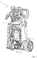
- in perspektivischer, geschnittener Darstellung den Hochdruckreiniger mit Druckabschaltventil nach
Fig. 1 , - Fig. 3
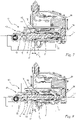
- in schematischer Darstellung die Funktion der Hydraulikeinheit in erster Schließstellung,
- Fig. 4
- in schematischer Darstellung die Funktion der Hydraulikeinheit in Überdruckstellung,
- Fig. 5
- in schematischer Darstellung die Funktion der Hydraulikeinheit in zweiter Schließstellung,
- Fig. 6
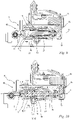
- in einer Schnittdarstellung das erfindungsgemäße Druckabschaltventil in erster Schließstellung,
- Fig. 7
- in einer Schnittdarstellung das Druckabschaltventil nach
Fig. 6 mit Pumpe in der ersten Schließstellung, - Fig. 8
- in einer Schnittdarstellung das Druckabschaltventil nach
Fig. 6 mit Pumpe in der zweiten Schließstellung, - Fig. 9
- in einer Schnittdarstellung das Druckabschaltventil nach
Fig. 6 mit Pumpe in der Überdruckstellung und - Fig. 10
- in einer Schnittdarstellung eine weitere Ausführung des erfindungsgemäßen Druckabschaltventils mit gleichen Durchmessern der Drosselspalte.
-
Fig. 1 zeigt eine schematische Darstellung einer Ausführung des erfindungsgemäßen Hochdruckreinigers 1. Der Hochdruckreiniger 1 umfasst ein Gehäuse 2, das einzelne Systemkomponenten einer Hydraulikeinheit 50 (Fig. 3 bis 5 ) umgibt und diese beispielsweise vor Spritzwasser schützt. An dem Gehäuse 2 ist ein Niederdruckanschluss 4 vorgesehen, über welchen eine Ansaugleitung 5 (Fig. 3 bis 5 ) des Hochdruckreinigers 1 mit einem externen Flüssigkeitsanschluss 6 (Fig. 3 bis 5 ), insbesondere mit einem Wasseranschluss, verbindbar ist. Demnach wird dem Hochdruckreiniger 1 in dessen Betrieb über den Niederdruckanschluss 4 eine Reinigungsflüssigkeit zugeführt. Die Reinigungsflüssigkeit ist vorzugsweise Wasser. Es können auch andere Flüssigkeiten, beispielsweise Wasser versetzt mit einem Reinigungsmittel, als Reinigungsflüssigkeit vorgesehen sein. Auf dem Gehäuse 2 des Hochdruckreinigers 1 ist eine Schlauchtrommel 7 vorgesehen. Auf der Schlauchtrommel 7 ist ein Hochdruckschlauch 8 aufgewickelt. Der Hochdruckschlauch 8 ist an seinem einen Ende mit einer Hochdruckleitung 38 (Figuren 3 bis 5 ) des Hochdruckreinigers 1 verbunden. An dem anderen Ende des Hochdruckschlauchs 8 ist ein Druckanschluss 9 vorgesehen, an dem ein Spritzaufsatz 3 (Figuren 3 bis 5 ), beispielsweise eine Spritzpistole mit einem Düsenkopf, anschließbar ist. - Wie in
Fig. 1 gezeigt, umfasst der Hochdruckreiniger 1 einen Betätigungsschalter 37, mittels dessen der Hochdruckreiniger 1, insbesondere dessen Hydraulikeinheit 50, an- und ausgeschaltet werden kann. Zudem ist auf der Oberseite des Gehäuses 2 ein Haltegriff 35 vorgesehen. Der Hochdruckreiniger 1 kann an seinem Haltegriff 35 angehoben, insbesondere getragen oder über seine an der Unterseite des Gehäuses 2 angeordneten Räder 36 gezogen werden. - Wie in
Fig. 2 gezeigt, umfasst der Hochdruckreiniger 1 eine Pumpe 51, die durch einen Antriebsmotor 52 (Fig. 3 bis 5 ) angetrieben ist. Der Antriebsmotor 52 ist im Ausführungsbeispiel als Elektromotor ausgebildet. In einer alternativen Ausführung des Hochdruckreinigers 1 kann der Antriebsmotor 52 auch als Verbrennungsmotor ausgebildet sein. An der Pumpe 51 ist ein Druckabschaltventil 10 vorgesehen, welches wie die Pumpe 51 ein Teil der Hydraulikeinheit 50 ist. Benachbart zum Druckabschaltventil 10 sind ein Schaltelement 26 und ein Schalter 28 vorgesehen. Das Druckabschaltventil 10 ist über das Schaltelement 26 mit dem Schalter 28 vorzugsweise mechanisch wirkverbunden. Wirkt das Druckabschaltventil 10 auf das Schaltelement 26, betätigt dieses den Schalter 28. Der Schalter 28 aktiviert oder deaktiviert den Antriebsmotor 52 der Pumpe 51. - Nachfolgend ist die Funktionsweise der Hydraulikeinheit 50 des Hochdruckreinigers 1 beschrieben, die in den
Figuren 3 bis 5 schematisch dargestellt ist:
Die Hydraulikeinheit 50 umfasst die Pumpe 51 mit dem Antriebsmotor 52, die Ansaugleitung 5, die Hochdruckleitung 38, den Spritzaufsatz 3 und das Druckabschaltventil 10. Die Ansaugleitung 5 ist mit dem Flüssigkeitsanschluss 6 verbunden, der im bevorzugten Ausführungsbeispiel als ein Wasseranschluss ausgebildet ist. Die Flüssigkeit strömt von dem Flüssigkeitsanschluss 6 über die Ansaugleitung 5 zur Pumpe 51. Treibt der Antriebsmotor 52 die Pumpe 51 an, fördert die Pumpe 51 die Flüssigkeit über die Hochdruckleitung 38 zum Spritzaufsatz 3. Wird der Spritzaufsatz 3 durch den Bediener betätigt, strömt aus dem Düsenkopf des Spritzaufsatzes 3 die Flüssigkeit in hoher Geschwindigkeit aus. Die Hochdruckleitung 38 ist mit der Ansaugleitung 5 über das Druckabschaltventil 10 strömungsverbunden. - Wie in
Fig. 3 gezeigt, umfasst das Druckabschaltventil 10 ein Ventilgehäuse 11, einen im Ventilgehäuse 11 linear beweglichen Ventilkörper 16, einen Einlass 13 zum Zuführen von Flüssigkeit und einen Auslass 14 zum Abführen von Flüssigkeit. Der Einlass 13 des Druckabschaltventils 10 ist an der Hochdruckleitung 38, der Auslass 14 des Druckabschaltventils 10 an der Ansaugleitung 5 angeschlossen. Das Druckabschaltventil 10 weist zwischen dem Einlass 13 und dem Auslass 14 des Druckabschaltventils 10 eine Strömungsverbindung 12 auf (Fig. 4 ). Das Druckabschaltventil 10 umfasst einen Ventilsitz 15 und ein dem Ventilsitz 15 zugeordnetes Ventilglied 20. Im Ausführungsbeispiel ist der Ventilsitz 15 an dem Ventilgehäuse 11 ausgebildet. Das Ventilglied 20 ist vorzugsweise an dem Ventilkörper 16 ausgebildet. Ferner umfasst das Druckabschaltventil 10 ein Federelement 21, das auf den Ventilkörper 16 wirkt und das Ventilglied 20 in Richtung zum Ventilsitz 15 drückt. - In
Fig. 3 ist die Hydraulikeinheit 50 mit geöffnetem Spritzaufsatz 3 dargestellt. Bei geöffnetem Spritzaufsatz 3 baut sich der Druck in der Hochdruckleitung 38 ab. Das Ventilglied 20 wird durch das Federelement 21 auf den Ventilsitz 15 gedrückt. Das Druckabschaltventil 10 ist in einer ersten Schließstellung 40. Der Ventilkörper 16 gibt den Schalter 28 frei, wodurch der Antriebsmotor 52 der Pumpe 51 aktiviert ist. Die Flüssigkeit wird von der Pumpe 51 über die Hochdruckleitung 38 zum Düsenkopf des Spritzaufsatzes 3 geleitet, aus dem diese mit hoher Geschwindigkeit austritt. - In
Fig. 4 ist das Hydrauliksystem 50 mit geschlossenem Spritzaufsatz 3 gezeigt. Wird der Spritzaufsatz 3 bei laufendem Antriebsmotor 52 geschlossen, entsteht in der Hochdruckleitung 38 ein Überdruck. Dieser Überdruck bewirkt am Einlass des Druckabschaltventils 10 eine Druckkraft auf den Ventilkörper 16, wodurch dieser entgegen der Federkraft des Federelementes 21 in Richtung des Schalters 28 gedrückt wird. Der Schalter 28 wird durch den Ventilkörper 16 betätigt, wodurch der Antriebsmotor 52 deaktiviert wird. Der Überdruck übt zudem eine derart hohe Druckkraft auf den Ventilkörper 16 aus, dass dieser in eine Überdruckstellung 43 übergeht, in der Einlass 13 und Auslass 14 des Druckabschaltventils 10 strömungsverbunden sind. Es erfolgt ein Druckausgleich zwischen der Hochdruckleitung 38 und der Ansaugleitung 5, wodurch insbesondere die mechanischen Belastungen, die auf die Hochdruckleitung 38, die Pumpe 51 bzw. deren Hochdruckteile wirken, reduziert werden. - In
Fig. 5 ist das Hydrauliksystem 50 mit geschlossenem Spritzaufsatz 3 gezeigt, wobei sich das Druckabschaltventil 10 in der zweiten Schließstellung 42 bei deaktiviertem Antriebsmotor 52 befindet. In der zweiten Schließstellung 42 sind Einlass 13 und Auslass 14 des Druckabschaltventils 10 nicht mehr strömungsverbunden. Der auf der Hochdruckleitung 38 noch bestehende Druck bewirkt eine Druckkraft, die im Gleichgewicht mit der Federkraft des Federelementes steht. Das Federelement 21 ist dabei so ausgelegt, dass der Ventilkörper 16 derart ausgelenkt ist, dass die Strömungsverbindung 12 zwischen Einlass 13 und Auslass 14 des Druckabschaltventils 10 unterbrochen ist, der Schalter 28 jedoch durch den Ventilkörper 16 aktiviert ist. Erst mit Aktivierung des Spritzaufsatzes 3, wie inFig. 3 gezeigt, fällt der Druck an der Hochdruckleitung 38 wieder ausreichend ab, wodurch der Ventilkörper 16 in die erste Schließstellung 40 rückt und den Schalter 28 wieder freigibt. - In
Fig. 6 ist in einer Schnittdarstellung das erfindungsgemäße Druckabschaltventil 10 in der ersten Schließstellung 40 gezeigt. Der Ventilkörper 16 ist im bevorzugten Ausführungsbeispiel als ein Kolben ausgebildet. Der Ventilkörper 16 besitzt eine Längsachse 17 und ist im Ventilgehäuse 11 in Richtung seiner Längsachse 17 beweglich gelagert. Der Ventilkörper 16 umfasst an seinem dem Einlass 13 des Druckabschaltventils 10 zugewandten Ende einen Kolbenkopf 23 und an seinem dem Einlass 13 des Druckabschaltventils 10 abgewandten Ende einen Kolbenfuß 22. Der Kolbenfuß 22 dient dazu, das Schaltelement 26 zu betätigen (Fig. 7 bis 10 ). - Wie in
Fig. 6 gezeigt, umfasst das Druckabschaltventil 10 einen ersten Drosselspalt 31 und einen zweiten Drosselspalt 32. Die Drosselspalte 31, 32 sind zwischen dem Ventilgehäuse 11 und dem Ventilkörper 16 ausgebildet. Die Drosselspalte 31, 32 sind Teil der Strömungsverbindung 12 und liegen zwischen dem Einlass 13 und dem Auslass 14 des Druckabschaltventils 10. Der erste Drosselspalt 31 liegt stromaufwärts vorzugsweise näher am Einlass als der zweite Drosselspalt 32. Die Drosselspalte 31, 32 sind in Reihe zueinander angeordnet. Der erste Drosselspalt 31 weist eine in Richtung der Längsachse 17 gemessene Spaltlänge b auf. Der zweite Drosselspalt 32 weist eine in Richtung der Längsachse 17 gemessene Spaltlänge c auf. Der erste Drosselspalt 31 und der zweite Drosselspalt 32 bilden zusammen einen effektiven Drosselspalt 30. Der effektive Drosselspalt 30 weist eine Spaltlänge a auf, wobei die Spaltlänge a der Summe aus der Spaltlänge b des ersten Drosselspaltes 31 und der Spaltlänge c des zweiten Drosselspaltes 32 entspricht. Die Drosselspalte 31, 32 sind am Kolbenkopf 23 des Ventilkörpers 16 ausgebildet. - Wie in
Fig. 6 gezeigt, erstrecken sich im bevorzugten Ausführungsbeispiel der erste Drosselspalt 31 und der zweite Drosselspalt 32 lediglich über im Wesentlichen zylindrische Abschnitte des Ventilkörpers 16 und des Ventilgehäuses 11. Das Ventilgehäuse 11 weist entlang der Drosselspalte 31, 32 aus fertigungstechnischen Gründen eine geringfügige Entformungsschräge gegenüber der Längsachse 17 auf. Im Wesentlichen zylindrisch ist derart zu verstehen, dass der mit der Längsachse 17 des Ventilkörpers 16 geschlossene Winkel nicht größer als 2° ist. Der erste Drosselspalt 31 und der zweite Drosselspalt 32 weisen jeweils eine radial zur Längsachse 17 gemessene Spalthöhe e auf. Die Spalthöhe e entspricht einer gemittelten Spalthöhe. Demnach errechnet sich die Spalthöhe aus der halben Differenz des Innendurchmessers des Ventilgehäuses 11 und des Außendurchmessers des Ventilkörpers 16. Diese sind mittig an den Drosselspalten 31, 32, wie in derFig. 6 dargestellt, zu messen. Die Spalthöhe e des ersten Drosselspaltes 31 und des zweiten Drosselspaltes 32 ist vorzugsweise kleiner 0,25 mm, insbesondere kleiner 0,2 mm. Die Spalthöhe e des ersten Drosselspaltes 31 und des zweiten Drosselspaltes 32 ist bevorzugt größer 0,05 mm, insbesondere größer 0,1 mm. Im bevorzugten Ausführungsbeispiel sind die Spalthöhe e des ersten Drosselspaltes 31 und des zweiten Drosselspaltes 32 gleich. Es kann in einer alternativen Ausführung zweckmäßig sein, verschiedene Spalthöhen e für die Drosselspalte 31, 32 vorzusehen. - Wie in
Fig. 6 gezeigt, besitzt der Ventilkörper 16 einen radial zur Längsachse 17 gemessenen, maximalen Durchmesser d. Die Gesamtlänge a des effektiven Drosselspaltes 30 beträgt in der Schließstellung 40 des Druckabschaltventils 10 mindestens 50%, insbesondere mindestens 65%, vorzugsweise in etwa 85% des maximalen Durchmessers d des Ventilkörpers 16. Der maximale Durchmesser d des Ventilkörpers ist vorzugsweise lediglich an einem der Drosselspalte 31, 32 zu messen. Durch die große Gesamtlänge a des effektiven Drosselspaltes 30 bleibt der Strömungswiderstand trotz der hohen Spalthöhe e der Drosselspalte 31, 32 ausreichend groß. - Wie in
Fig. 6 gezeigt, besitzt der erste Drosselspalt 31 einen radial zur Längsachse 17 gemessenen ersten Durchmesser di. Der zweite Drosselspalt 32 besitzt einen radial zur Längsachse 17 gemessenen zweiten Durchmesser d2. Die Durchmesser der Drosselspalte entsprechen den Außendurchmessern des Ventilkörpers 16 an den jeweiligen Drosselspalten 31, 32. Im Ausführungsbeispiel nachFig. 6 ist der Durchmesser d2 des zweiten Drosselspaltes 32 größer als der Durchmesser di des ersten Drosselspaltes 31. Die verschiedenen Durchmesser di, d2 der Drosselspalte 31, 32 bilden eine Überströmungskammer 18, die zwischen dem ersten Drosselspalt 31 und dem zweiten Drosselspalt 32 vorgesehen ist. Die Überströmungskammer 18 ist in Richtung der Längsachse 17 an ihrem dem Einlass 13 zugewandten Ende durch eine Gehäuseschulter 33 des Ventilgehäuses 11 und an ihrem dem Einlass 13 abgewandten Ende durch eine Kolbenschulter 34 des Ventilkörpers begrenzt (Fig. 8 ). - Wie in
Fig. 6 gezeigt, ist an dem Ventilkörper 16 ein sich bezüglich der Längsachse 17 in Richtung vom Einlass 13 des Druckabschaltventils 10 weg verjüngender Abschnitt 27 ausgebildet. Der Abschnitt 27 schließt sich in der ersten Schließstellung des Druckabschaltventils 10 an dem vom Einlass 13 abgewandten Ende des zweiten Drosselspaltes 32 an. Der sich verjüngende Abschnitt 27 geht in eine sich radial zur Längsachse 17 erstreckende weitere Kolbenschulter 45 des Ventilköpers 16 über. An dieser Kolbenschulter 45 ist ein Stützring 46 vorgesehen, über welchen das Federelement 21 auf den Ventilkörper 16 wirkt. In der ersten Schließstellung 40 spannt das Federelement 21 den Ventilkörper 16 mit seinem konisch ausgebildeten Ventilglied 20 gegen den Ventilsitz 21 des Ventilgehäuses 11. - Wie in
Fig. 6 gezeigt, umfasst das Druckabschaltventil 10 einen Dichtring 19. Der Dichtring 19 ist bevorzugt am Ventilgehäuse 11 gehalten. Der Dichtring ist vorzugsweise als ein O-Ring ausgebildet. In der ersten Schließstellung 40 des Druckabschaltventils 10 liegt der Dichtring 19 in Richtung der Längsachse 17 auf Höhe des sich verjüngenden Abschnitts 27 des Ventilkörpers 16. In der ersten Schließstellung 40 steht der Dichtring 19 mit dem Ventilkörper 16 nicht in Kontakt. - Im bevorzugten Ausführungsbeispiel besteht der Ventilkörper und/oder das Ventilgehäuse aus Kunststoff, insbesondere aus Polyoxymethylen (POM). Die große Spalthöhe e der Drosselspalte 31, 32 und die Gesamtspaltlänge a des effektiven Drosselspaltes 30 lassen den Einsatz derartiger Werkstoffe zu, wodurch Herstellungskosten gesenkt werden können.
- Nachfolgend ist anhand der
Figuren 7 bis 9 die Funktion des erfindungsgemäßen Druckabschaltventils beschrieben:
InFig. 7 ist das Druckabschaltventil 10 nachFig. 6 eingebaut in der Pumpe 51 in seiner ersten Schließstellung 40 gezeigt. Das Ventilglied 20 des Ventilkörpers 16 liegt an dem Ventilsitz 15 des Ventilgehäuses 11 an. Die Strömungsverbindung 12 zwischen Einlass 13 und Auslass 14 des Druckabschaltventils 10 ist unterbrochen. Dieser Zustand liegt wie oben beschrieben vor, wenn der Spritzaufsatz 3 aktiviert ist und die Reinigungsflüssigkeit aus dem Spritzaufsatz 3 ausströmt. Das Federelement 21 ist dabei derart ausgelegt, dass auch bei Druckschwankungen an der Hochdruckleitung 38 das Ventilglied 20 des Ventilkörpers 16 gegen den Ventilsitz 15 des Ventilgehäuses 11 gedrückt ist und das Druckabschaltventil 10 in der ersten Schließstellung 40 verbleibt. Derartige Druckschwankungen können beispielsweise durch Strömungsimpulse der Pumpe 51 entstehen. - Wie in
Fig. 7 gezeigt, kontaktiert der Ventilkörper 16 den Dichtring 19 in der ersten Schließstellung 40 nicht. Liegt eine Leckage zwischen Ventilsitz 15 und Ventilglied 20 vor, kann das Fluid über den effektiven Drosselspalt 30 an der Dichtung 19 vorbei vom Einlass 13 bis zum Auslass 14 des Ventilgehäuses 11 strömen. Die durch die Leckage verursachten, geringen Strömungen verursachen somit einlassseitig keine Druckerhöhung. Dadurch wird ein ungewolltes Schalten des Druckabschaltventils 10 durch Leckage vermieden. Eine derartige Leckage kann durch Fertigungstoleranzen, aber auch durch Verschleiß von Ventilsitz 15 und Ventilglied 20 entstehen. - Deaktiviert der Bediener den Spritzaufsatz 3, tritt aus diesem keine Reinigungsflüssigkeit mehr aus. Die Pumpe 51 wird durch den Antriebsmotor 52 weiter betrieben, wodurch der Druck an der Hochdruckleitung 28 weiter ansteigt. Aufgrund des erhöhten Druckes wirkt am Einlass 13 eine Druckkraft auf den Ventilkörper 16, die derart hoch ist, dass der Ventilkörper 16 in Richtung seiner Längsachse 17 weg vom Einlass 13 geschoben wird. Der Ventilsitz 15 wird von dem Ventilglied 20 freigegeben, wodurch eine Strömungsverbindung 12 zwischen dem Einlass 13 und dem Auslass 14 besteht. Das Druckabschaltventil 10 befindet sich in einer Offenstellung 41. Der durch den effektiven Drosselspalt 30 erzeugte Strömungswiderstand ist jedoch so groß, dass der Druck am Einlass den Ventilkörper 16 weiter weg vom Einlass 13 entgegen der Federkraft des Federelementes 21 schiebt. Der Ventilkörper 16 bewegt sich von der ersten Schließstellung 40 bis zur zweiten Schließstellung 42, in welcher der Ventilkörper 16 den Dichtring 19 kontaktiert. Wie in
Fig. 7 gezeigt, legt der Ventilkörper 16 dabei den Schließweg g zurück. - Wie in
Fig. 8 gezeigt, hat der Ventilkörper 16 den Schließweg g überbrückt und steht in Kontakt mit dem Dichtring 19. Das Druckabschaltventil 10 ist in der zweiten Schließstellung 42 geschlossen, da der Dichtring 19 den Ventilkörper 16 kontaktiert. Der Druck an der Hochdruckleitung 38 bzw. am Einlass 13 des Ventilgehäuses 11 wird weiter erhöht. Folglich steigt auch die auf den Ventilkörper 16 wirkende Druckkraft an, wodurch der Ventilkörper 16 weiter in Richtung zum Schaltelement 26 geschoben wird. Der Ventilkörper 16 betätigt mit seinem Kolbenfuß 22 das Schaltelement 26 und drückt dieses gegen den Schalter 28. Der Schalter 28 deaktiviert wiederum den Antriebsmotor 52 der Pumpe 51. Das Druckabschaltventil 10 befindet sich in der zweiten Schließstellung 42 (Fig. 8 ). - In
Fig. 9 ist das Druckabschaltventil 10 in seiner Überdruckstellung 43 gezeigt. Wie bereits oben beschrieben, soll ein Druckausgleich zwischen der Hochdruckleitung 38 und der Ansaugleitung 5 erfolgen, um die mechanischen Belastungen auf die Systemkomponenten zu reduzieren. Nachdem der Ventilkörper 16 das Schaltelement 26 betätigt hat, wird dieser durch die Druckkraft weiter in Richtung weg vom Einlass des Druckabschaltventils 10 gedrückt, bis der Ventilkörper 16 die Überdruckstellung 43 erreicht. Befindet sich der Ventilkörper 16 in der Überdruckstellung 43, hat dieser von der ersten Schließstellung 40 bis zur Überdruckstellung 43 einen in Richtung der Längsachse 17 gemessenen maximalen Ventilweg h zurückgelegt. In der Überdruckstellung 43 steht der Dichtring 19 nicht mehr im Kontakt mit dem Ventilkörper 16. In dieser Stellung des Druckabschaltventils 10 liegt die Überströmungskammer 18 in Richtung der Längsachse 17 auf Höhe des Dichtrings 19, wodurch die Strömungsverbindung 12 wieder freigegeben ist. Dadurch sind die Hochdruckleitung 38 und die Ansaugleitung 5 durch das Druckabschaltventil 10 miteinander verbunden. Es erfolgt ein Druckausgleich zwischen der Hochdruckleitung 38 und der Ansaugleitung 5. Der Druck an der Hochdruckleitung 38 reduziert sich, wodurch sich die Druckkraft auf den Ventilkörper 16 wieder reduziert. Das Federelement 21 drückt den Ventilkörper 16 wieder zurück in Richtung zum Einlass 13 bis der Ventilkörper 16 den Dichtring 19 wieder kontaktiert. Es kann kein weiterer Druckausgleich mehr erfolgen. Der Ventilkörper 16 verbleibt in der zweiten Schließstellung (Fig. 8 ) bei deaktiviertem Antriebsmotor, bis der Bediener den Spritzaufsatz 3 wieder aktiviert. - Wie in
Fig. 9 gezeigt, ist der Ventilweg h des Ventilkörpers 16 kleiner als die Gesamtlänge a des effektiven Drosselspaltes 30. Im bevorzugten Ausführungsbeispiel entspricht der Ventilweg h des Ventilkörpers 16 weniger als 90%, insbesondere weniger als 80%, vorzugsweise in etwa 75% der Gesamtlänge a des effektiven Drosselspaltes 30. - In
Fig. 10 ist eine weitere Ausführung des erfindungsgemäßen Druckabschaltventils 10 gezeigt. Diese Ausführung unterscheidet sich von der in denFiguren 6 bis 9 dargestellten Ausführung lediglich in der Ausgestaltung der Durchmesser di, d2 der Drosselspalte 31, 32. Der erste Durchmesser di des ersten Drosselspaltes 31 entspricht dem zweiten Durchmesser d2 des zweiten Drosselspaltes 32. Die Überströmungskammer 18 ist durch einen Freistich zwischen dem ersten Drosselspalt 31 und dem zweiten Drosselspalt 32 gebildet. Die Überströmungskammer 18 ermöglicht in der Überdruckstellung 43 des Druckabschaltventils 10 eine Strömungsverbindung 12 zwischen dem Einlass 13 und dem Auslass 14 des Druckabschaltventils 10. Ein Druckausgleich zwischen der Hochdruckleitung 38 und der Ansaugleitung 5 ist ermöglicht. - Wie in
Fig. 7 gezeigt, weist das Druckabschaltventil 10 einen in Richtung der Längsachse 17 gemessenen Schaltweg f auf. Der Schaltweg f ist der Weg des Ventilkörpers 16, den der Ventilkörper 16 zurücklegen muss, um das Schaltelement 26 zu betätigen. Anders formuliert entspricht der Schaltweg f dem in Richtung der Längsachse 17 gemessenen Abstand zwischen dem Kolbenfuß 22 des Ventilkörpers 16 und dem Schaltelement 26 entlang der Längsachse 17. Der Schaltweg f ist vorzugsweise kürzer als die Gesamtlänge a des effektiven Drosselspaltes 30. Der Schaltweg f beträgt höchstens 50%, insbesondere höchstens 35% der Gesamtlänge a des effektiven Drosselspaltes 30.
Claims (15)
- Druckabschaltventil für einen Hochdruckreiniger,
umfassend ein Ventilgehäuse (11) mit einem Ventilsitz (15), mindestens einen Einlass (13) zum Zuführen einer Flüssigkeit, mindestens einen Auslass (14) zum Abführen der Flüssigkeit und einen Ventilkörper (16) mit einer Längsachse (17), wobei der Ventilkörper (16) ein dem Ventilsitz (15) zugeordnetes Ventilglied (20) aufweist, wobei in einer ersten Schließstellung (40) des Druckabschaltventils (10) der Ventilsitz (15) durch das Ventilglied (20) verschlossen ist und die Strömungsverbindung (12) zwischen dem Einlass (13) und dem Auslass (14) unterbrochen ist,
wobei das Druckabschaltventil (10) zwischen dem Ventilgehäuse (11) und dem Ventilkörper (16) einen effektiven Drosselspalt (30) mit einer in Richtung der Längsachse (17) des Ventilkörpers (16) gemessenen Gesamtlänge (a) aufweist, wobei der effektive Drosselspalt (30) Teil der Strömungsverbindung (12) zwischen dem Einlass (13) und dem Auslass (14) ist,
und wobei der Ventilkörper (16) einen sich radial zur Längsachse (17) erstreckenden maximalen Durchmesser (d) aufweist,
dadurch gekennzeichnet, dass die Gesamtlänge (a) des effektiven Drosselspalts (30) in der ersten Schließstellung (40) des Druckabschaltventils (10) mindestens 50% des maximalen Durchmessers (d) des Ventilkörpers (16) beträgt. - Druckabschaltventil nach Anspruch 2,
dadurch gekennzeichnet, dass der effektive Drosselspalt (30) eine radial zur Längsachse (17) des Ventilkörpers (16) gemessene Spalthöhe (e) besitzt, wobei die Spalthöhe (e) höchstens 0,25 mm, insbesondere höchstens 0,2 mm beträgt. - Druckabschaltventil nach Anspruch 1 oder 2,
dadurch gekennzeichnet, dass der effektive Drosselspalt (30) einen ersten Drosselspalt (31) mit einem ersten Durchmesser (di) und einen zweiten Drosselspalt (32) mit einem zweiten Durchmesser (d2) umfasst. - Druckabschaltventil nach Anspruch 3,
dadurch gekennzeichnet, dass zwischen dem ersten Drosselspalt (31) und dem zweiten Drosselspalt (32) zwischen dem Ventilkörper (16) und dem Ventilgehäuse (11) eine Überströmungskammer (18) vorgesehen ist. - Druckabschaltventil nach Anspruch 3 oder 4,
dadurch gekennzeichnet, dass der erste Durchmesser (di) des ersten Drosselspaltes (31) kleiner ist als der zweite Durchmesser (d2) des zweiten Drosselspaltes (32). - Druckabschaltventil nach einem der Ansprüche 3 oder 4,
dadurch gekennzeichnet, dass der erste Durchmesser (di) des ersten Drosselspaltes (31) in etwa dem zweiten Durchmesser (d2) des zweiten Drosselspaltes (32) entspricht. - Druckabschaltventil nach einem der Ansprüche 3 bis 6,
dadurch gekennzeichnet, dass der zweite Drosselspalt (32) ein von dem ersten Drosselspalt (31) abgewandtes Ende aufweist, an dem sich ein in Richtung der Längsachse (17) verjüngender Abschnitt (27) des Ventilkörpers (16) anschließt. - Druckabschaltventil nach einem der Ansprüche 1 bis 7,
dadurch gekennzeichnet, dass das Ventilglied (20) des Ventilkörpers (16) in Richtung zum Ventilsitz (15) des Ventilgehäuses (11) konisch ausgebildet ist. - Druckabschaltventil nach einem der Ansprüche 1 bis 8,
dadurch gekennzeichnet, dass das Druckabschaltventil (10) ein auf den Ventilkörper (16) wirkendes Federelement (21) umfasst, wobei das Federelement (21) den Ventilkörper (16) gegen den Ventilsitz (15) des Ventilgehäuses (11) spannt. - Druckabschaltventil nach einem der Ansprüche 1 bis 9,
dadurch gekennzeichnet, dass das Druckabschaltventil (10) eine Offenstellung (41), eine zweite Schließstellung (42) und eine Überdruckstellung (43) aufweist, wobei in der Überdruckstellung (43) der Einlass (13) und der Auslass (14) des Ventilgehäuses (11) strömungsverbunden sind. - Druckabschaltventil nach Anspruch 10,
dadurch gekennzeichnet, dass das Druckabschaltventil (10) derart ausgebildet ist, dass bei Überdruck am Einlass (14) des Ventilgehäuses (11) der Ventilkörper (16) entlang der Längsachse (17) in Richtung weg vom Einlass (13) gedrückt wird, wodurch das Druckabschaltventil (10) von der zweiten Schließstellung (42) in die Überdruckstellung (43) übergeht. - Druckabschaltventil nach Anspruch 10 oder 11,
dadurch gekennzeichnet, dass das Druckabschaltventil (10) einen in Richtung der Längsachse (17) gemessenen maximalen Ventilweg (h) aufweist, den der Ventilkörper (16) von der ersten Schließstellung (40) bis zur Überdruckstellung (43) zurücklegt, und dass der Ventilweg (h) des Ventilkörpers (16) kleiner als die Gesamtlänge (a) des effektiven Drosselspaltes (30) ist. - Druckabschaltventil nach Anspruch 12,
dadurch gekennzeichnet, dass der Ventilweg (h) des Ventilkörpers (16) höchstens 90%, insbesondere höchstens 80%, vorzugsweise in etwa 75% der Gesamtlänge (a) des effektiven Drosselspaltes (30) entspricht. - Druckabschaltventil nach einem der Ansprüche 1 bis 13,
dadurch gekennzeichnet, dass der Ventilkörper (16) und/oder das Ventilgehäuse aus Polyoxymethylen (POM) bestehen. - Hochdruckreiniger mit einem Druckabschaltventil nach einem der Ansprüche 1 bis 14.
Priority Applications (4)
| Application Number | Priority Date | Filing Date | Title |
|---|---|---|---|
| EP20203837.8A EP3988787B1 (de) | 2020-10-26 | 2020-10-26 | Druckabschaltventil für einen hochdruckreiniger und hochdruckreiniger mit einem druckabschaltventil |
| BR102021021016-8A BR102021021016A2 (pt) | 2020-10-26 | 2021-10-20 | Válvula de interrupção de pressão para um limpador de alta pressão e um limpador de alta pressão com uma válvula de interrupção de pressão |
| US17/508,672 US20220126329A1 (en) | 2020-10-26 | 2021-10-22 | Pressure shutoff valve for a pressure washer and pressure washer with a pressure shutoff valve |
| CN202111248828.5A CN114484070A (zh) | 2020-10-26 | 2021-10-26 | 高压清洁器的压力切断阀和带有压力切断阀的高压清洁器 |
Applications Claiming Priority (1)
| Application Number | Priority Date | Filing Date | Title |
|---|---|---|---|
| EP20203837.8A EP3988787B1 (de) | 2020-10-26 | 2020-10-26 | Druckabschaltventil für einen hochdruckreiniger und hochdruckreiniger mit einem druckabschaltventil |
Publications (2)
| Publication Number | Publication Date |
|---|---|
| EP3988787A1 true EP3988787A1 (de) | 2022-04-27 |
| EP3988787B1 EP3988787B1 (de) | 2025-01-01 |
Family
ID=73020067
Family Applications (1)
| Application Number | Title | Priority Date | Filing Date |
|---|---|---|---|
| EP20203837.8A Active EP3988787B1 (de) | 2020-10-26 | 2020-10-26 | Druckabschaltventil für einen hochdruckreiniger und hochdruckreiniger mit einem druckabschaltventil |
Country Status (4)
| Country | Link |
|---|---|
| US (1) | US20220126329A1 (de) |
| EP (1) | EP3988787B1 (de) |
| CN (1) | CN114484070A (de) |
| BR (1) | BR102021021016A2 (de) |
Families Citing this family (3)
| Publication number | Priority date | Publication date | Assignee | Title |
|---|---|---|---|---|
| USD984765S1 (en) * | 2020-09-23 | 2023-04-25 | Jian Shao | Pressure washer |
| DE102023129104A1 (de) * | 2023-10-23 | 2025-04-24 | Alfred Kärcher SE & Co. KG | Druckreinigungsgerät |
| USD1058970S1 (en) * | 2024-08-21 | 2025-01-21 | Ningbo Ruizhe Technology Co., Ltd | High pressure washer |
Citations (4)
| Publication number | Priority date | Publication date | Assignee | Title |
|---|---|---|---|---|
| GB2054757A (en) * | 1979-07-25 | 1981-02-18 | Zahnradfabrik Friedrichshafen | High-pressure pump with pressure regulator |
| DE19548497C1 (de) * | 1995-12-22 | 1997-04-03 | Kaercher Gmbh & Co Alfred | Hochdruckreinigungsger{t |
| DE102005007141A1 (de) * | 2005-02-17 | 2006-08-24 | Hydac Electronic Gmbh | Ventil |
| US20130306166A1 (en) * | 2012-05-16 | 2013-11-21 | Ulrich Erb | Pressure-limiting valve |
Family Cites Families (7)
| Publication number | Priority date | Publication date | Assignee | Title |
|---|---|---|---|---|
| US2594626A (en) * | 1946-09-09 | 1952-04-29 | Clarence E Earle | Safety valve |
| DE19500706C2 (de) * | 1995-01-12 | 2003-09-25 | Bosch Gmbh Robert | Zumeßventil zur Dosierung von Flüssigkeiten oder Gasen |
| DE10312672A1 (de) * | 2003-02-26 | 2004-09-09 | Bosch Rexroth Ag | Direktgesteuertes Druckbegrenzungsventil |
| CN203395198U (zh) * | 2013-07-29 | 2014-01-15 | 四川杰特机器有限公司 | 间隙节流调压阀 |
| EP3015749B1 (de) * | 2014-10-29 | 2020-05-27 | Asco Numatics GmbH | Vorrichtung zur Steuerung fluidischer Medien sowie Verwendung eines Formteils in einer solchen Vorrichtung |
| DE102016201696A1 (de) * | 2016-02-04 | 2017-08-10 | Voith Patent Gmbh | Hydraulikventil |
| WO2021237031A1 (en) * | 2020-05-22 | 2021-11-25 | Microfluidics International Corporation | High-pressure priming valve |
-
2020
- 2020-10-26 EP EP20203837.8A patent/EP3988787B1/de active Active
-
2021
- 2021-10-20 BR BR102021021016-8A patent/BR102021021016A2/pt unknown
- 2021-10-22 US US17/508,672 patent/US20220126329A1/en active Pending
- 2021-10-26 CN CN202111248828.5A patent/CN114484070A/zh active Pending
Patent Citations (4)
| Publication number | Priority date | Publication date | Assignee | Title |
|---|---|---|---|---|
| GB2054757A (en) * | 1979-07-25 | 1981-02-18 | Zahnradfabrik Friedrichshafen | High-pressure pump with pressure regulator |
| DE19548497C1 (de) * | 1995-12-22 | 1997-04-03 | Kaercher Gmbh & Co Alfred | Hochdruckreinigungsger{t |
| DE102005007141A1 (de) * | 2005-02-17 | 2006-08-24 | Hydac Electronic Gmbh | Ventil |
| US20130306166A1 (en) * | 2012-05-16 | 2013-11-21 | Ulrich Erb | Pressure-limiting valve |
Also Published As
| Publication number | Publication date |
|---|---|
| CN114484070A (zh) | 2022-05-13 |
| US20220126329A1 (en) | 2022-04-28 |
| BR102021021016A2 (pt) | 2022-05-10 |
| EP3988787B1 (de) | 2025-01-01 |
Similar Documents
| Publication | Publication Date | Title |
|---|---|---|
| DE69500878T2 (de) | Druckventil | |
| EP3988787B1 (de) | Druckabschaltventil für einen hochdruckreiniger und hochdruckreiniger mit einem druckabschaltventil | |
| DE29502829U1 (de) | Kraftstoffeinspritzeinrichtung für Brennkraftmaschinen | |
| DE102010000508A1 (de) | Pulsationsreduktionsvorrichtung | |
| DE102014223240A1 (de) | Niederdruckregelsystem einer Kraftstofffördereinrichtung eines Kraftstoffeinspritzsystems sowie ein Absteuerventil dazu | |
| DE102018200612A1 (de) | Hochdruckanschluss für eine Kraftstoffhochdruckpumpe sowie Kraftstoffhochdruckpumpe | |
| WO2012150308A2 (de) | Verfahren und vorrichtung zum steuern eines ventils | |
| DE10259808A1 (de) | Regelstrahlpumpe | |
| EP1123461B1 (de) | Injektor für ein common-rail-einspritzsystem für brennkraftmaschinen mit kompakter bauweise | |
| EP3274220A1 (de) | Ventil und reinigungseinrichtung für ein kraftfahrzeug | |
| WO2011039115A1 (de) | Pumpe für ein hochdruckreinigungsgerät | |
| EP0130306A2 (de) | Verfahren und Vorrichtung zum Steuern eines Rohrtrenners | |
| DE102011083005B4 (de) | Verfahren zur Spülung eines Ankerraums eines zur Steuerung eines Fluidmassenstroms vorgesehenen Magnetventils und Magnetventil | |
| EP2150696A1 (de) | Injektor für eine kraftstoffeinspritzanlage | |
| EP4172486A1 (de) | Durchflussbegrenzer für ein kraftstoffeinspritzsystem sowie kraftstoffeinspritzsystem mit einem durchflussbegrenzer | |
| EP0608796B1 (de) | Druck-Saugverteiler eines Hochdruckreinigungsgerätes mit zusätzlichem Steuerventil | |
| EP4010580B1 (de) | Kraftstoffinjektor mit einem durchflussbegrenzer für ein kraftstoffeinspritzsystem | |
| EP2249024B1 (de) | Kraftstoffinjektor | |
| DE102015226070A1 (de) | Kraftstoffinjektor | |
| DE19938999C2 (de) | Einspritzventil mit einem geschmierten Übertragungselement | |
| DE19908595A1 (de) | Ventilanordnung für Schaltvorgänge von Flüssigkeiten | |
| DE102010001612A1 (de) | Kraftstoffinjektor | |
| DE10050599B4 (de) | Einspritzventil mit einem Pumpkolben | |
| EP1573196B1 (de) | Injektor mit einer vorrichtung zum abdichten einer aktoreinheit sowie dichtring | |
| DE10160490B4 (de) | Kraftstoff-Einspritzvorrichtung, Kraftstoffsystem sowie Brennkraftmaschine |
Legal Events
| Date | Code | Title | Description |
|---|---|---|---|
| PUAI | Public reference made under article 153(3) epc to a published international application that has entered the european phase |
Free format text: ORIGINAL CODE: 0009012 |
|
| STAA | Information on the status of an ep patent application or granted ep patent |
Free format text: STATUS: THE APPLICATION HAS BEEN PUBLISHED |
|
| AK | Designated contracting states |
Kind code of ref document: A1 Designated state(s): AL AT BE BG CH CY CZ DE DK EE ES FI FR GB GR HR HU IE IS IT LI LT LU LV MC MK MT NL NO PL PT RO RS SE SI SK SM TR |
|
| STAA | Information on the status of an ep patent application or granted ep patent |
Free format text: STATUS: REQUEST FOR EXAMINATION WAS MADE |
|
| 17P | Request for examination filed |
Effective date: 20221027 |
|
| RBV | Designated contracting states (corrected) |
Designated state(s): AL AT BE BG CH CY CZ DE DK EE ES FI FR GB GR HR HU IE IS IT LI LT LU LV MC MK MT NL NO PL PT RO RS SE SI SK SM TR |
|
| REG | Reference to a national code |
Ref country code: DE Ref legal event code: R079 Free format text: PREVIOUS MAIN CLASS: F04B0049030000 Ipc: F16K0017040000 Ref country code: DE Ref legal event code: R079 Ref document number: 502020010087 Country of ref document: DE Free format text: PREVIOUS MAIN CLASS: F04B0049030000 Ipc: F16K0017040000 |
|
| GRAP | Despatch of communication of intention to grant a patent |
Free format text: ORIGINAL CODE: EPIDOSNIGR1 |
|
| STAA | Information on the status of an ep patent application or granted ep patent |
Free format text: STATUS: GRANT OF PATENT IS INTENDED |
|
| RIC1 | Information provided on ipc code assigned before grant |
Ipc: F04B 49/24 20060101ALI20240410BHEP Ipc: F04B 49/22 20060101ALI20240410BHEP Ipc: F04B 49/08 20060101ALI20240410BHEP Ipc: F04B 49/03 20060101ALI20240410BHEP Ipc: F16K 47/08 20060101ALI20240410BHEP Ipc: F16K 37/00 20060101ALI20240410BHEP Ipc: F16K 17/04 20060101AFI20240410BHEP |
|
| INTG | Intention to grant announced |
Effective date: 20240424 |
|
| INTG | Intention to grant announced |
Effective date: 20240424 |
|
| GRAJ | Information related to disapproval of communication of intention to grant by the applicant or resumption of examination proceedings by the epo deleted |
Free format text: ORIGINAL CODE: EPIDOSDIGR1 |
|
| STAA | Information on the status of an ep patent application or granted ep patent |
Free format text: STATUS: REQUEST FOR EXAMINATION WAS MADE |
|
| GRAP | Despatch of communication of intention to grant a patent |
Free format text: ORIGINAL CODE: EPIDOSNIGR1 |
|
| STAA | Information on the status of an ep patent application or granted ep patent |
Free format text: STATUS: GRANT OF PATENT IS INTENDED |
|
| INTC | Intention to grant announced (deleted) | ||
| INTG | Intention to grant announced |
Effective date: 20240916 |
|
| GRAS | Grant fee paid |
Free format text: ORIGINAL CODE: EPIDOSNIGR3 |
|
| GRAA | (expected) grant |
Free format text: ORIGINAL CODE: 0009210 |
|
| STAA | Information on the status of an ep patent application or granted ep patent |
Free format text: STATUS: THE PATENT HAS BEEN GRANTED |
|
| AK | Designated contracting states |
Kind code of ref document: B1 Designated state(s): AL AT BE BG CH CY CZ DE DK EE ES FI FR GB GR HR HU IE IS IT LI LT LU LV MC MK MT NL NO PL PT RO RS SE SI SK SM TR |
|
| REG | Reference to a national code |
Ref country code: GB Ref legal event code: FG4D Free format text: NOT ENGLISH |
|
| REG | Reference to a national code |
Ref country code: CH Ref legal event code: EP |
|
| REG | Reference to a national code |
Ref country code: DE Ref legal event code: R096 Ref document number: 502020010087 Country of ref document: DE |
|
| REG | Reference to a national code |
Ref country code: IE Ref legal event code: FG4D Free format text: LANGUAGE OF EP DOCUMENT: GERMAN |
|
| REG | Reference to a national code |
Ref country code: LT Ref legal event code: MG9D |
|
| REG | Reference to a national code |
Ref country code: NL Ref legal event code: MP Effective date: 20250101 |
|
| PG25 | Lapsed in a contracting state [announced via postgrant information from national office to epo] |
Ref country code: NL Free format text: LAPSE BECAUSE OF FAILURE TO SUBMIT A TRANSLATION OF THE DESCRIPTION OR TO PAY THE FEE WITHIN THE PRESCRIBED TIME-LIMIT Effective date: 20250101 |
|
| PG25 | Lapsed in a contracting state [announced via postgrant information from national office to epo] |
Ref country code: FI Free format text: LAPSE BECAUSE OF FAILURE TO SUBMIT A TRANSLATION OF THE DESCRIPTION OR TO PAY THE FEE WITHIN THE PRESCRIBED TIME-LIMIT Effective date: 20250101 |
|
| PG25 | Lapsed in a contracting state [announced via postgrant information from national office to epo] |
Ref country code: PL Free format text: LAPSE BECAUSE OF FAILURE TO SUBMIT A TRANSLATION OF THE DESCRIPTION OR TO PAY THE FEE WITHIN THE PRESCRIBED TIME-LIMIT Effective date: 20250101 |
|
| PG25 | Lapsed in a contracting state [announced via postgrant information from national office to epo] |
Ref country code: ES Free format text: LAPSE BECAUSE OF FAILURE TO SUBMIT A TRANSLATION OF THE DESCRIPTION OR TO PAY THE FEE WITHIN THE PRESCRIBED TIME-LIMIT Effective date: 20250101 |
|
| PG25 | Lapsed in a contracting state [announced via postgrant information from national office to epo] |
Ref country code: IS Free format text: LAPSE BECAUSE OF FAILURE TO SUBMIT A TRANSLATION OF THE DESCRIPTION OR TO PAY THE FEE WITHIN THE PRESCRIBED TIME-LIMIT Effective date: 20250501 Ref country code: NO Free format text: LAPSE BECAUSE OF FAILURE TO SUBMIT A TRANSLATION OF THE DESCRIPTION OR TO PAY THE FEE WITHIN THE PRESCRIBED TIME-LIMIT Effective date: 20250401 |
|
| PG25 | Lapsed in a contracting state [announced via postgrant information from national office to epo] |
Ref country code: HR Free format text: LAPSE BECAUSE OF FAILURE TO SUBMIT A TRANSLATION OF THE DESCRIPTION OR TO PAY THE FEE WITHIN THE PRESCRIBED TIME-LIMIT Effective date: 20250101 |
|
| PG25 | Lapsed in a contracting state [announced via postgrant information from national office to epo] |
Ref country code: LV Free format text: LAPSE BECAUSE OF FAILURE TO SUBMIT A TRANSLATION OF THE DESCRIPTION OR TO PAY THE FEE WITHIN THE PRESCRIBED TIME-LIMIT Effective date: 20250101 Ref country code: PT Free format text: LAPSE BECAUSE OF FAILURE TO SUBMIT A TRANSLATION OF THE DESCRIPTION OR TO PAY THE FEE WITHIN THE PRESCRIBED TIME-LIMIT Effective date: 20250502 |
|
| PG25 | Lapsed in a contracting state [announced via postgrant information from national office to epo] |
Ref country code: GR Free format text: LAPSE BECAUSE OF FAILURE TO SUBMIT A TRANSLATION OF THE DESCRIPTION OR TO PAY THE FEE WITHIN THE PRESCRIBED TIME-LIMIT Effective date: 20250402 Ref country code: BG Free format text: LAPSE BECAUSE OF FAILURE TO SUBMIT A TRANSLATION OF THE DESCRIPTION OR TO PAY THE FEE WITHIN THE PRESCRIBED TIME-LIMIT Effective date: 20250101 |
|
| PG25 | Lapsed in a contracting state [announced via postgrant information from national office to epo] |
Ref country code: CZ Free format text: LAPSE BECAUSE OF FAILURE TO SUBMIT A TRANSLATION OF THE DESCRIPTION OR TO PAY THE FEE WITHIN THE PRESCRIBED TIME-LIMIT Effective date: 20250101 |
|
| PG25 | Lapsed in a contracting state [announced via postgrant information from national office to epo] |
Ref country code: SE Free format text: LAPSE BECAUSE OF FAILURE TO SUBMIT A TRANSLATION OF THE DESCRIPTION OR TO PAY THE FEE WITHIN THE PRESCRIBED TIME-LIMIT Effective date: 20250101 |
|
| REG | Reference to a national code |
Ref country code: DE Ref legal event code: R097 Ref document number: 502020010087 Country of ref document: DE |
|
| PG25 | Lapsed in a contracting state [announced via postgrant information from national office to epo] |
Ref country code: SM Free format text: LAPSE BECAUSE OF FAILURE TO SUBMIT A TRANSLATION OF THE DESCRIPTION OR TO PAY THE FEE WITHIN THE PRESCRIBED TIME-LIMIT Effective date: 20250101 |
|
| PG25 | Lapsed in a contracting state [announced via postgrant information from national office to epo] |
Ref country code: DK Free format text: LAPSE BECAUSE OF FAILURE TO SUBMIT A TRANSLATION OF THE DESCRIPTION OR TO PAY THE FEE WITHIN THE PRESCRIBED TIME-LIMIT Effective date: 20250101 |
|
| PG25 | Lapsed in a contracting state [announced via postgrant information from national office to epo] |
Ref country code: IT Free format text: LAPSE BECAUSE OF FAILURE TO SUBMIT A TRANSLATION OF THE DESCRIPTION OR TO PAY THE FEE WITHIN THE PRESCRIBED TIME-LIMIT Effective date: 20250101 |
|
| PG25 | Lapsed in a contracting state [announced via postgrant information from national office to epo] |
Ref country code: EE Free format text: LAPSE BECAUSE OF FAILURE TO SUBMIT A TRANSLATION OF THE DESCRIPTION OR TO PAY THE FEE WITHIN THE PRESCRIBED TIME-LIMIT Effective date: 20250101 |
|
| PG25 | Lapsed in a contracting state [announced via postgrant information from national office to epo] |
Ref country code: RO Free format text: LAPSE BECAUSE OF FAILURE TO SUBMIT A TRANSLATION OF THE DESCRIPTION OR TO PAY THE FEE WITHIN THE PRESCRIBED TIME-LIMIT Effective date: 20250101 |
|
| PG25 | Lapsed in a contracting state [announced via postgrant information from national office to epo] |
Ref country code: SK Free format text: LAPSE BECAUSE OF FAILURE TO SUBMIT A TRANSLATION OF THE DESCRIPTION OR TO PAY THE FEE WITHIN THE PRESCRIBED TIME-LIMIT Effective date: 20250101 |
|
| PLBE | No opposition filed within time limit |
Free format text: ORIGINAL CODE: 0009261 |
|
| STAA | Information on the status of an ep patent application or granted ep patent |
Free format text: STATUS: NO OPPOSITION FILED WITHIN TIME LIMIT |
|
| REG | Reference to a national code |
Ref country code: CH Ref legal event code: L10 Free format text: ST27 STATUS EVENT CODE: U-0-0-L10-L00 (AS PROVIDED BY THE NATIONAL OFFICE) Effective date: 20251112 |
|
| 26N | No opposition filed |
Effective date: 20251002 |
|
| PGFP | Annual fee paid to national office [announced via postgrant information from national office to epo] |
Ref country code: DE Payment date: 20251028 Year of fee payment: 6 |
|
| REG | Reference to a national code |
Ref country code: CH Ref legal event code: H13 Free format text: ST27 STATUS EVENT CODE: U-0-0-H10-H13 (AS PROVIDED BY THE NATIONAL OFFICE) Effective date: 20260527 |
|
| PG25 | Lapsed in a contracting state [announced via postgrant information from national office to epo] |
Ref country code: LU Free format text: LAPSE BECAUSE OF NON-PAYMENT OF DUE FEES Effective date: 20251026 |
|
| REG | Reference to a national code |
Ref country code: BE Ref legal event code: MM Effective date: 20251031 |
|
| GBPC | Gb: european patent ceased through non-payment of renewal fee |
Effective date: 20251026 |
|
| PG25 | Lapsed in a contracting state [announced via postgrant information from national office to epo] |
Ref country code: LT Free format text: LAPSE BECAUSE OF FAILURE TO SUBMIT A TRANSLATION OF THE DESCRIPTION OR TO PAY THE FEE WITHIN THE PRESCRIBED TIME-LIMIT Effective date: 20250101 |
|
| PG25 | Lapsed in a contracting state [announced via postgrant information from national office to epo] |
Ref country code: MC Free format text: LAPSE BECAUSE OF FAILURE TO SUBMIT A TRANSLATION OF THE DESCRIPTION OR TO PAY THE FEE WITHIN THE PRESCRIBED TIME-LIMIT Effective date: 20250101 |
|
| PG25 | Lapsed in a contracting state [announced via postgrant information from national office to epo] |
Ref country code: RS Free format text: LAPSE BECAUSE OF FAILURE TO SUBMIT A TRANSLATION OF THE DESCRIPTION OR TO PAY THE FEE WITHIN THE PRESCRIBED TIME-LIMIT Effective date: 20250101 |
|
| PG25 | Lapsed in a contracting state [announced via postgrant information from national office to epo] |
Ref country code: GB Free format text: LAPSE BECAUSE OF NON-PAYMENT OF DUE FEES Effective date: 20251026 |
|
| PG25 | Lapsed in a contracting state [announced via postgrant information from national office to epo] |
Ref country code: CH Free format text: LAPSE BECAUSE OF NON-PAYMENT OF DUE FEES Effective date: 20251031 Ref country code: BE Free format text: LAPSE BECAUSE OF NON-PAYMENT OF DUE FEES Effective date: 20251031 |
|
| PG25 | Lapsed in a contracting state [announced via postgrant information from national office to epo] |
Ref country code: FR Free format text: LAPSE BECAUSE OF NON-PAYMENT OF DUE FEES Effective date: 20251031 |