EP3988701A1 - Drum washing machine and control method therefor - Google Patents
Drum washing machine and control method therefor Download PDFInfo
- Publication number
- EP3988701A1 EP3988701A1 EP20827500.8A EP20827500A EP3988701A1 EP 3988701 A1 EP3988701 A1 EP 3988701A1 EP 20827500 A EP20827500 A EP 20827500A EP 3988701 A1 EP3988701 A1 EP 3988701A1
- Authority
- EP
- European Patent Office
- Prior art keywords
- inner drum
- drainage channel
- drainage
- drum
- operating state
- Prior art date
- Legal status (The legal status is an assumption and is not a legal conclusion. Google has not performed a legal analysis and makes no representation as to the accuracy of the status listed.)
- Granted
Links
Images



Classifications
-
- D—TEXTILES; PAPER
- D06—TREATMENT OF TEXTILES OR THE LIKE; LAUNDERING; FLEXIBLE MATERIALS NOT OTHERWISE PROVIDED FOR
- D06F—LAUNDERING, DRYING, IRONING, PRESSING OR FOLDING TEXTILE ARTICLES
- D06F39/00—Details of washing machines not specific to a single type of machines covered by groups D06F9/00 - D06F27/00
- D06F39/08—Liquid supply or discharge arrangements
- D06F39/083—Liquid discharge or recirculation arrangements
-
- D—TEXTILES; PAPER
- D06—TREATMENT OF TEXTILES OR THE LIKE; LAUNDERING; FLEXIBLE MATERIALS NOT OTHERWISE PROVIDED FOR
- D06F—LAUNDERING, DRYING, IRONING, PRESSING OR FOLDING TEXTILE ARTICLES
- D06F37/00—Details specific to washing machines covered by groups D06F21/00 - D06F25/00
- D06F37/02—Rotary receptacles, e.g. drums
- D06F37/04—Rotary receptacles, e.g. drums adapted for rotation or oscillation about a horizontal or inclined axis
-
- D—TEXTILES; PAPER
- D06—TREATMENT OF TEXTILES OR THE LIKE; LAUNDERING; FLEXIBLE MATERIALS NOT OTHERWISE PROVIDED FOR
- D06F—LAUNDERING, DRYING, IRONING, PRESSING OR FOLDING TEXTILE ARTICLES
- D06F23/00—Washing machines with receptacles, e.g. perforated, having a rotary movement, e.g. oscillatory movement, the receptacle serving both for washing and for centrifugally separating water from the laundry
- D06F23/02—Washing machines with receptacles, e.g. perforated, having a rotary movement, e.g. oscillatory movement, the receptacle serving both for washing and for centrifugally separating water from the laundry and rotating or oscillating about a horizontal axis
- D06F23/025—Washing machines with receptacles, e.g. perforated, having a rotary movement, e.g. oscillatory movement, the receptacle serving both for washing and for centrifugally separating water from the laundry and rotating or oscillating about a horizontal axis with a rotatable imperforate tub
-
- D—TEXTILES; PAPER
- D06—TREATMENT OF TEXTILES OR THE LIKE; LAUNDERING; FLEXIBLE MATERIALS NOT OTHERWISE PROVIDED FOR
- D06F—LAUNDERING, DRYING, IRONING, PRESSING OR FOLDING TEXTILE ARTICLES
- D06F33/00—Control of operations performed in washing machines or washer-dryers
- D06F33/30—Control of washing machines characterised by the purpose or target of the control
- D06F33/32—Control of operational steps, e.g. optimisation or improvement of operational steps depending on the condition of the laundry
- D06F33/42—Control of operational steps, e.g. optimisation or improvement of operational steps depending on the condition of the laundry of draining
Definitions
- the present disclosure relates to the technical field of laundry equipment, in particular to a drum washing machine and a control method thereof.
- washing machines help people get rid of the trouble of laundry and bring great convenience to people.
- existing washing machines generally include an inner drum and an outer drum, there are a plurality of dewatering holes in the wall of the inner drum. In the washing process, washing water between the inner drum and the outer drum will not be used, causing this part of washing water to be wasted, and dirt generated in the washing process will be accumulated as the water flows between the inner drum and the outer drum, so that with long-term use, the accumulation of the dirt will affect the washing effect and reduce the user use experience.
- a drum washing machine including a box body, an inner drum and an outer drum are arranged in the box body, a door seal is arranged between the outer drum and the box body, the inner drum is connected with a driving device.
- the inner drum is a holeless inner drum and is a conical drum with a small diameter at the bottom of the drum and a large diameter at the opening of the drum, the opening of the inner drum is curved inwards, the door seal is provided with a water inlet guide pipe, one end of the water inlet guide pipe is connected with a rapid washing water heating device, the other end of the water inlet guide pipe extends through the door seal into the inner drum, and the outer drum is provided with a drainage port and a water pressure detection device.
- the inner drum of the present disclosure is the holeless inner drum, water inflow of the inner drum is realized through the water inlet guide pipe disposed on the door seal, and water is discharged in the dewatering process through the shape of the inner drum itself, so that water is prevented from being accumulated between the inner drum and the outer drum, and the washing water consumption is greatly reduced.
- the above-mentioned disclosure provides the drum washing machine with the holeless inner drum, which solves the problems of waste of water between the inner drum and the outer drum and the accumulation of dirt between the inner drum and the outer drum.
- the inner drum of the existing drum washing machine is only designed as a holeless structure, which has little practical significance. Since the inner drum not only needs to rotate for washing and dewatering, but also contains water, how to realize the drainage of the washing machine with the holeless inner drum becomes the first problem of the inner drum being holeless.
- a first objective of the present disclosure is to provide a drum washing machine, specifically, the following technical solutions are adopted.
- a drum washing machine comprising:
- the inner drum has a first operating state rotating in a clockwise direction and a second operating state rotating in a counterclockwise direction
- the blocking component keeps the inner drum drainage port closed in the first operating state and keeps the inner drum drainage port open in the second operating state; or the blocking component keeps the inner drum drainage port closed in the second operating state, and keeps the inner drum drainage port open in the first operating state.
- the drainage channel is disposed on a side wall of the inner drum and arranged in a circumferential direction of the inner drum, and the blocking component is of a one-way valve structure; and preferably, the drainage channel is disposed on an inner side wall or an outer side wall of the inner drum.
- the drainage channel is disposed on the inner side wall of the inner drum and is provided with a water inlet communicating with the inner drum and a water outlet communicating with the inner drum drainage port
- the one-way valve structure comprises a valve ball that moves between the water inlet and the water outlet of the drainage channel along with rotation of the inner drum, the valve ball keeps blocking the water inlet in the first operating state so that the drainage channel is closed and is far away from the water inlet in the second operating state so that the drainage channel is opened; or the valve ball keeps blocking the water inlet in the second operating state so that the drainage channel is closed and is far away from the water inlet in the first operating state so that the drainage channel is opened.
- the one-way valve structure further includes a centrifugal block that may move between the water inlet and the water outlet of the drainage channel along with rotation of the inner drum, and the centrifugal block is connected to the valve ball.
- the drainage channel is disposed on the inner side wall of the inner drum, and has a water inlet communicating with the inner drum and a water outlet communicating with the inner drum drainage port
- the one-way valve structure comprises a one-way valve plate installed at the water inlet, the one-way valve plate keeps blocking the water inlet in the first operating state so that the drainage channel is closed and opening the water inlet in the second operating state so that the drainage channel is opened; or the one-way valve plate keeps blocking the water inlet in the second operating state so that the drainage channel is closed and opening the water inlet in the first operating state so that the drainage channel is opened.
- the drainage sealing device comprises an elastic member, and the elastic member is in an elastic compression state to provide the one-way valve structure with elastic force for keeping blocking the water inlet; the one-way valve structure is subjected to the elastic force of the elastic member in the first operating state to keep blocking the water inlet so that the drainage channel is closed and overcomes the elastic force of the elastic member in the second operating state to be far away from the water inlet so that the drainage channel is opened; or the one-way valve structure is subjected to the elastic force of the elastic member in the second operating state to keep blocking the water inlet so that the drainage channel is closed and overcomes the elastic force of the elastic member in the first operating state to be far away from the water inlet so that the drainage channel is opened.
- a second objective of the present disclosure is to provide a control method of the above-mentioned drum washing machine, specifically, the following technical solutions are adopted.
- a blocking component is controlled to close a drainage channel, and an inner drum is closed to independently contain washing water; and when the washing machine drains water, the blocking component is controlled to open the drainage channel, and the water in the inner drum enters into the drainage channel and is discharged from an inner drum drainage port.
- the inner drum when the washing machine performs washing, the inner drum is controlled to keep operating in the first operating state or second operating state, and a one-way valve structure is in a normally closed state to close the drainage channel; and when the washing machine drains water, the inner drum is controlled to keep operating in the second operating state or first operating state, and the one-way valve structure opens the drainage channel.
- the present disclosure provides the drum washing machine with a structure design of a holeless inner drum.
- the inner drum independently contains the washing water during washing, and there is no water between the inner drum and an outer drum, which avoids the possibility of dirt adhesion between the inner drum and the outer drum, greatly improves user health and user experience, and greatly saves water resources.
- the drum washing machine of the present disclosure realizes the opening and closing control over the inner drum drainage port through the drainage sealing device
- the drainage sealing device includes the drainage channel communicating with the inner drum drainage port and the blocking component that controls the opening and closing of the drainage channel
- the opening and closing control over the inner drum drainage port is converted into on-off control of the drainage channel
- the blocking component can be designed to have different motion states by using the shifting of working states of the inner drum, thereby switching the on-off of the drainage channel
- the structure is simple, and control is easy to realize.
- an embodiment provides a drum washing machine with a structural design of a holeless inner drum.
- the inner drum independently contains washing water during washing, and there is no water between the inner drum and an outer drum, which avoids the possibility of dirt adhesion between the inner drum and the outer drum, greatly improves user health and user experience, and greatly saves water resources.
- the drum washing machine of the present embodiment has a housing 1, and the housing 1 includes: an upper panel, a front panel, a back panel, and a bottom plate. Feet are installed and fixed on the bottom plate to support the entire washing machine.
- the housing 1 is provided with an outer drum 2 inside, and an inner drum 3 is coaxially disposed in the outer drum 2.
- the main purpose of the outer drum 2 is to collect drained water of the inner drum 3 and drained water from the high-speed centrifugal dewatering of the inner drum 3, the outer drum 2 is connected to a drainage pipe, the drainage pipe is provided with a drainage control device that controls on and off of the drainage pipe, and the drainage control device is a drainage pump or a drain valve.
- the inner drum 3 rotates, which, preferably, is provided with lifting ribs to continuously lift, drop and beat clothes, so as to wash the clothes.
- the inner drum 3 is of a holeless structure.
- the outer drum 2 is provided a central mounting hole, and a bearing is installed and fixed in the central mounting hole.
- An inner drum shaft, which is tightly connected to the inner drum 3, passes through the bearing shown and is connected to a drive motor.
- An openable and closable inner drum door is installed on a front opening of the inner drum 3, thereby realizing that the inner drum 3 is of a sealed cabin structure.
- the housing 1 of the present embodiment is provided with a machine door that can be opened or closed.
- the drum washing machine includes:
- the drum washing machine of the present embodiment realizes the opening and closing control over the inner drum drainage port 9 through the drainage sealing device
- the drainage sealing device includes the drainage channel 7 communicating with the inner drum drainage port 9 and the blocking component 8 that controls the opening and closing of the drainage channel 7, the opening and closing control over the inner drum drainage port 9 is converted into on-off control of the drainage channel 7, and the blocking component 8 can be designed to have different motion states by using the shifting of working states of the inner drum, thereby switching on-off of the drainage channel 7.
- the drainage channel 7 of the present embodiment may be formed between a separate member 6 installed on the inner wall of the inner drum and the inner wall of the inner drum, or may be formed by interlacing and then connecting the butting positions of the side walls of the inner drum, and a water inlet of the drainage channel 7 and the inner drum drainage port 9 are respectively disposed at positions of two connecting faces.
- the inner drum 3 has a first operating state rotating in a clockwise direction and a second operating state rotating in a counterclockwise direction
- the blocking component 8 keeps the inner drum drainage port 9 closed in the first operating state and keeps the inner drum drainage port 9 open in the second operating state; or the blocking component 8 keeps the inner drum drainage port 9 closed in the second operating state and keeps the inner drum drainage port 9 open in the first operating state.
- the blocking component 8 of the present embodiment uses the change of a rotation direction of the inner drum 3 to switch the opening and closing states of the inner drum drainage port 9, so as to realize the change from controlling the opening and closing of the inner drum drainage port 9 to controlling the opening and closing of the drainage channel 7. Meanwhile, according to the working characteristics of the inner drum of the washing machine, the control over the drainage channel 7 by the blocking component 8 is realized, the structure is simple, and control is easy to realize.
- the drainage channel 7 of the present embodiment is disposed on the side wall of the inner drum 3 and arranged in a circumferential direction of the inner drum 3, and the blocking component 8 is of a one-way valve structure.
- the blocking component 8 of the present embodiment uses the one-way valve structure to realize on-off control of the drainage channel 7.
- the one-way valve structure keeps the drainage channel in a closed state when the inner drum is at a standstill or in the first operating state or second operating state.
- the one-way valve structure is activated and the drainage channel is opened.
- the drainage channel 7 is disposed on an inner side wall or an outer side wall of the inner drum 3.
- the drainage channel 7 described according to the present embodiment is disposed on the inner side wall of the inner drum 3 and has a water inlet 5 communicating with the inner drum 3 and a water outlet communicating with the inner drum drainage port 9.
- the one-way valve structure includes a valve ball 10 that moves between the water inlet 5 and the water outlet of the drainage channel 7 along with rotation of the inner drum.
- the valve ball 10 keeps blocking the water inlet 5 in the first operating state so that the drainage channel is closed and is far away from the water inlet in the second operating state so that the drainage channel 7 is opened; or the valve ball 10 keeps blocking the water inlet 5 in the second operating state so that the drainage channel is closed and is far away from the water inlet in the first operating state so that the drainage channel 7 is opened.
- the one-way valve structure further includes a centrifugal block 12 that moves between the water inlet 5 and the water outlet of the drainage channel 7 along with rotation of the inner drum 3, and the centrifugal block 12 is connected to the valve ball 10.
- the centrifugal block 12 is used, the mass of the centrifugal block 12 is generally larger than that of the valve ball 10, and the centrifugal movement with the rotation of the inner drum is more stable, so that the state of the valve ball is kept more stable, and the possibility that turbulent flow opens a ball valve by mistake is avoided.
- the initial state of the inner drum of the present embodiment is such that the position of the water inlet 5 of the drainage channel 7 is higher than the highest water level in the inner drum 3, and no washing water enters into the drainage channel 7.
- the inner drum 3 When washing starts, the inner drum 3 is controlled to rotate clockwise, the centrifugal block 12 moves relative to the inner drum along the drainage channel 7 toward the side of the water inlet 5, the centrifugal block 12 drives the ball valve 9 to move to the water inlet 5 to block the water inlet, and the drainage channel is closed.
- the inner drum is controlled to rotate counterclockwise, the centrifugal block 12 moves relative to the inner drum along the drainage channel 7 to be away from the side of the water inlet 5, the centrifugal block 12 drives the ball valve 9 to be away from the water inlet 5, the drainage channel is opened, and water in the inner drum enters into the drainage channel 7 and is discharged from the inner drum through the inner drum drainage port 9.
- the inner drum is controlled to keep rotating counterclockwise and return to the initial position of the water inlet 5 of the drainage channel 7, the water level in the inner drum 3 drops, the water inlet is higher than the water level in the inner drum, and no water enters into the drainage channel.
- the drainage channel 7 of the present embodiment is disposed on the inner side wall of the inner drum 3, and has a water inlet 5 communicating with the inner drum 3 and a water outlet communicating with the inner drum drainage port.
- the one-way valve structure includes a one-way valve plate 13 installed at the water inlet. The one-way valve plate 13 keeps blocking the water inlet 5 in the first operating state so that the drainage channel is closed and opening the water inlet 5 in the second operating state so that the drainage channel 7 is opened; or the one-way valve plate 13 keeps blocking the water inlet 5 in the second operating state so that the drainage channel is closed and opening the water inlet 5 in the second operating state so that the drainage channel 7 is opened.
- the drainage sealing device of the present embodiment further includes an elastic member, and the elastic member is in an elastic compression state to provide the one-way valve structure with elastic force for keeping blocking the water inlet.
- the one-way valve structure is subjected to the elastic force of the elastic member in the first operating state or the second operating state to keep blocking the water inlet so that the drainage channel is closed, and overcomes the elastic force of the elastic member in the second operating state or the first operating state to be far away from the water inlet so that the drainage channel is opened.
- the drum washing machine of the present embodiment includes the drive motor and the inner drum shaft, the drive motor drives the inner drum 3 to rotate through a transmission connection between the inner drum shaft and the inner drum 3, the inner drum shaft internally has a hollow channel communicating with the inner drum 3, and a water inlet pipe of the washing machine communicates with the hollow channel of the inner drum shaft.
- the inner drum shaft is connected to the drive motor
- the drive motor includes a stator and a rotor
- the rotor is fixedly connected to the inner drum shaft; and a through hole is formed in the center of the rotor, and the water inlet pipe passes through the through hole of the rotor and then communicates with the hollow channel of the inner drum shaft.
- the present embodiment also solves the problem of how to accurately determine the amount of water entering the drum washing machine with the holeless inner drum, and the specific solution is as follows.
- the drum washing machine includes the inner drum 3 and the water inlet pipe communicating with the inner drum 3.
- the inner drum is the holeless inner drum and contains washing water when washing clothes.
- the water inlet pipe is provided with a flow sensor 1 configured to detect the flow of entering water.
- the flow sensor is installed on the water inlet pipe to monitor the flow during water entering, and when the set water entering flow is reached, a water inlet valve is closed to complete the water entering.
- the flow sensor is used to solve the water entering problem of the drum washing machine with the holeless inner drum according to the set water level, the washing effect is ensured, the structure is simple, and operation and control are convenient.
- the flow sensor is a rotor flow sensor, or a turbine flow sensor, or an ultrasonic flow sensor, or an electromagnetic flow sensor, or an orifice flow sensor.
- the present embodiment also solves the problem of how to avoid the unbalanced air pressure in a sealed compartment of the drum washing machine with the holeless inner drum. Specifically, the sudden water cut off of a solenoid valve, especially the water cut off of a tap water pipe network, creates a negative pressure and returns the washing water in the sealed compartment to the pipe network, or the problem that there is air inside, and water is difficult to enter.
- the drum washing machine of the present embodiment includes the inner drum 3, which is the holeless inner drum and contains washing water when washing clothes, and also includes an air pressure balance mechanism configured to make the inner drum 3 communicate with the external environment to balance the air pressure inside the inner drum.
- air in the sealed compartment of the inner drum may overflow through the balance mechanism under pressure to ensure the air pressure balance.
- the air pressure balance mechanism can also ensure the air pressure balance of the inner drum.
- the air pressure balance mechanism includes a pressure equalization channel disposed on the inner drum 3, and one end, communicating with the inner drum 3, of the pressure equalization channel is disposed at the position, close to a central axis of rotation, of the inner drum 3 and is always higher than the highest water level in the inner drum 3.
- the pressure equalization channel is formed on the inner drum shaft to make the inside of the inner drum 3 communicate with the external environment, and the highest water level in the inner drum 3 is lower than the inner drum shaft. In this way, the water in the inner drum can be prevented from flowing out of the pressure equalization channel.
- An embodiment also provides a control method of a drum washing machine, including:
- the inner drum is controlled to keep operating in a first operating state or the second operating state, and a one-way valve structure is in a normally closed state to close the drainage channel.
- the inner drum When the washing machine drains water, the inner drum is controlled to keep operating in the second operating state or first operating state, and the one-way valve structure opens the drainage channel.
- the inner drum is controlled to keep operating in the first operating state during washing or rinsing and to keep operating in the second operating state during drainage and dewatering; or the inner drum is controlled to keep operating in the second operating state during washing or rinsing and to keep operating in the second operating state during drainage and dewatering.
- the difference between the first operating state and the second operating state of the present embodiment is only in the direction of rotation.
- the rotation speeds of washing, dewatering, and drainage may also be different, and the rotation speeds of dewatering and drainage are greater than the rotation speed of washing and rinsing.
- the inner drum may also be controlled to switch between the first operating state and the second operating state.
- the inner drum since one of the operating states will drain water out of the inner drum, it is necessary to perform a water replenishment operation in the washing process, or, control the entering water of the inner drum to be higher than a set value.
Landscapes
- Engineering & Computer Science (AREA)
- Textile Engineering (AREA)
- Detail Structures Of Washing Machines And Dryers (AREA)
Abstract
Description
- The present disclosure relates to the technical field of laundry equipment, in particular to a drum washing machine and a control method thereof.
- As the most widely used household appliance in people's daily life, washing machines help people get rid of the trouble of laundry and bring great convenience to people. However, existing washing machines generally include an inner drum and an outer drum, there are a plurality of dewatering holes in the wall of the inner drum. In the washing process, washing water between the inner drum and the outer drum will not be used, causing this part of washing water to be wasted, and dirt generated in the washing process will be accumulated as the water flows between the inner drum and the outer drum, so that with long-term use, the accumulation of the dirt will affect the washing effect and reduce the user use experience.
- In order to solve the water-wasting problem of the washing machines, some patents have also been proposed. For example, there is a
Chinese disclosure patent with a patent number being 201410215346.3 - The above-mentioned disclosure provides the drum washing machine with the holeless inner drum, which solves the problems of waste of water between the inner drum and the outer drum and the accumulation of dirt between the inner drum and the outer drum. However, the inner drum of the existing drum washing machine is only designed as a holeless structure, which has little practical significance. Since the inner drum not only needs to rotate for washing and dewatering, but also contains water, how to realize the drainage of the washing machine with the holeless inner drum becomes the first problem of the inner drum being holeless.
- In view of this, the present disclosure is proposed.
- In order to solve the above problems, a first objective of the present disclosure is to provide a drum washing machine, specifically, the following technical solutions are adopted.
- A drum washing machine comprising:
- an inner drum, having a washing chamber for independently containing washing water;
- an inner drum drainage port being disposed in the inner drum; and
- a drainage sealing device being installed on the inner drum drainage port to control opening and closing of the inner drum drainage port; wherein
- the drainage sealing device includes a drainage channel communicating with the inner drum drainage port and a blocking component that controls opening and closing of the drainage channel.
- Further, the inner drum has a first operating state rotating in a clockwise direction and a second operating state rotating in a counterclockwise direction, and the blocking component keeps the inner drum drainage port closed in the first operating state and keeps the inner drum drainage port open in the second operating state; or the blocking component keeps the inner drum drainage port closed in the second operating state, and keeps the inner drum drainage port open in the first operating state.
- Further, the drainage channel is disposed on a side wall of the inner drum and arranged in a circumferential direction of the inner drum, and the blocking component is of a one-way valve structure; and
preferably, the drainage channel is disposed on an inner side wall or an outer side wall of the inner drum. - Further, the drainage channel is disposed on the inner side wall of the inner drum and is provided with a water inlet communicating with the inner drum and a water outlet communicating with the inner drum drainage port, the one-way valve structure comprises a valve ball that moves between the water inlet and the water outlet of the drainage channel along with rotation of the inner drum,
the valve ball keeps blocking the water inlet in the first operating state so that the drainage channel is closed and is far away from the water inlet in the second operating state so that the drainage channel is opened; or the valve ball keeps blocking the water inlet in the second operating state so that the drainage channel is closed and is far away from the water inlet in the first operating state so that the drainage channel is opened. - Further, the one-way valve structure further includes a centrifugal block that may move between the water inlet and the water outlet of the drainage channel along with rotation of the inner drum, and the centrifugal block is connected to the valve ball.
- Further, the drainage channel is disposed on the inner side wall of the inner drum, and has a water inlet communicating with the inner drum and a water outlet communicating with the inner drum drainage port, the one-way valve structure comprises a one-way valve plate installed at the water inlet,
the one-way valve plate keeps blocking the water inlet in the first operating state so that the drainage channel is closed and opening the water inlet in the second operating state so that the drainage channel is opened; or the one-way valve plate keeps blocking the water inlet in the second operating state so that the drainage channel is closed and opening the water inlet in the first operating state so that the drainage channel is opened. - Further, the drainage sealing device comprises an elastic member, and the elastic member is in an elastic compression state to provide the one-way valve structure with elastic force for keeping blocking the water inlet;
the one-way valve structure is subjected to the elastic force of the elastic member in the first operating state to keep blocking the water inlet so that the drainage channel is closed and overcomes the elastic force of the elastic member in the second operating state to be far away from the water inlet so that the drainage channel is opened; or the one-way valve structure is subjected to the elastic force of the elastic member in the second operating state to keep blocking the water inlet so that the drainage channel is closed and overcomes the elastic force of the elastic member in the first operating state to be far away from the water inlet so that the drainage channel is opened. - A second objective of the present disclosure is to provide a control method of the above-mentioned drum washing machine, specifically, the following technical solutions are adopted.
- According to the control method of the drum washing machine, when the washing machine performs washing, a blocking component is controlled to close a drainage channel, and an inner drum is closed to independently contain washing water; and
when the washing machine drains water, the blocking component is controlled to open the drainage channel, and the water in the inner drum enters into the drainage channel and is discharged from an inner drum drainage port. - Further, when the washing machine performs washing, the inner drum is controlled to keep operating in the first operating state or second operating state, and a one-way valve structure is in a normally closed state to close the drainage channel; and
when the washing machine drains water, the inner drum is controlled to keep operating in the second operating state or first operating state, and the one-way valve structure opens the drainage channel. - The present disclosure provides the drum washing machine with a structure design of a holeless inner drum. The inner drum independently contains the washing water during washing, and there is no water between the inner drum and an outer drum, which avoids the possibility of dirt adhesion between the inner drum and the outer drum, greatly improves user health and user experience, and greatly saves water resources.
- The drum washing machine of the present disclosure realizes the opening and closing control over the inner drum drainage port through the drainage sealing device, the drainage sealing device includes the drainage channel communicating with the inner drum drainage port and the blocking component that controls the opening and closing of the drainage channel, the opening and closing control over the inner drum drainage port is converted into on-off control of the drainage channel, the blocking component can be designed to have different motion states by using the shifting of working states of the inner drum, thereby switching the on-off of the drainage channel, the structure is simple, and control is easy to realize.
-
-
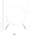
Fig. 1 is a schematic structural diagram of a drum washing machine of an embodiment of the present disclosure; -
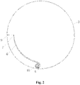
Fig. 2 is a schematic structural diagram I of an inner drum of a drum washing machine of an embodiment of the present disclosure; -
Fig. 3 is a schematic structural diagram II of an inner drum of a drum washing machine of an embodiment of the present disclosure (rotating clockwise, at the highest position of a water inlet of a drainage channel, water does not enter into the drainage channel); -
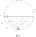
Fig. 4 is a schematic structural diagram III of an inner drum of a drum washing machine of an embodiment of the present disclosure (rotating clockwise, at the lowest position of a water inlet of a drainage channel, water does not enter into the drainage channel); -
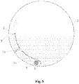
Fig. 5 is a schematic structural diagram IV of an inner drum of a drum washing machine of an embodiment of the present disclosure (rotating counterclockwise, at the lowest position of a water inlet of a drainage channel, water enters into the drainage channel); -
Fig. 6 is a schematic structural diagram V of an inner drum of a drum washing machine of an embodiment of the present disclosure (rotating counterclockwise, at the highest position of a water inlet of a drainage channel, a water level in the inner drum is lowered); and -
Fig. 7 is a schematic structural diagram VI of an inner drum of a drum washing machine of an embodiment of the present disclosure (rotating counterclockwise, at the highest position of a water inlet of a drainage channel, a water inlet valve plate is opened, and water enters into the drainage channel). - A drum washing machine and a control method thereof of the present disclosure will be described in detail below with reference to the accompanying drawings.
- As shown in
Figs. 1-7 , an embodiment provides a drum washing machine with a structural design of a holeless inner drum. The inner drum independently contains washing water during washing, and there is no water between the inner drum and an outer drum, which avoids the possibility of dirt adhesion between the inner drum and the outer drum, greatly improves user health and user experience, and greatly saves water resources. - The drum washing machine of the present embodiment has a
housing 1, and thehousing 1 includes: an upper panel, a front panel, a back panel, and a bottom plate. Feet are installed and fixed on the bottom plate to support the entire washing machine. Thehousing 1 is provided with anouter drum 2 inside, and aninner drum 3 is coaxially disposed in theouter drum 2. The main purpose of theouter drum 2 is to collect drained water of theinner drum 3 and drained water from the high-speed centrifugal dewatering of theinner drum 3, theouter drum 2 is connected to a drainage pipe, the drainage pipe is provided with a drainage control device that controls on and off of the drainage pipe, and the drainage control device is a drainage pump or a drain valve. Theinner drum 3 rotates, which, preferably, is provided with lifting ribs to continuously lift, drop and beat clothes, so as to wash the clothes. Theinner drum 3 is of a holeless structure. Theouter drum 2 is provided a central mounting hole, and a bearing is installed and fixed in the central mounting hole. An inner drum shaft, which is tightly connected to theinner drum 3, passes through the bearing shown and is connected to a drive motor. An openable and closable inner drum door is installed on a front opening of theinner drum 3, thereby realizing that theinner drum 3 is of a sealed cabin structure. - The
housing 1 of the present embodiment is provided with a machine door that can be opened or closed. - The drum washing machine, includes:
- an
inner drum 3, with a washing chamber capable of independently containing washing water; - an inner
drum drainage port 9, disposed in theinner drum 3; and - a drainage sealing device, installed at the inner
drum drainage port 9 to control opening and closing thereof; wherein - the drainage sealing device includes a
drainage channel 7 communicating with the innerdrum drainage port 9 and ablocking component 8 that controls opening and closing of thedrainage channel 7. - The drum washing machine of the present embodiment realizes the opening and closing control over the inner
drum drainage port 9 through the drainage sealing device, the drainage sealing device includes thedrainage channel 7 communicating with the innerdrum drainage port 9 and theblocking component 8 that controls the opening and closing of thedrainage channel 7, the opening and closing control over the innerdrum drainage port 9 is converted into on-off control of thedrainage channel 7, and theblocking component 8 can be designed to have different motion states by using the shifting of working states of the inner drum, thereby switching on-off of thedrainage channel 7. - The
drainage channel 7 of the present embodiment may be formed between aseparate member 6 installed on the inner wall of the inner drum and the inner wall of the inner drum, or may be formed by interlacing and then connecting the butting positions of the side walls of the inner drum, and a water inlet of thedrainage channel 7 and the innerdrum drainage port 9 are respectively disposed at positions of two connecting faces. - As an implementation of the present embodiment, the
inner drum 3 has a first operating state rotating in a clockwise direction and a second operating state rotating in a counterclockwise direction, and theblocking component 8 keeps the innerdrum drainage port 9 closed in the first operating state and keeps the innerdrum drainage port 9 open in the second operating state; or theblocking component 8 keeps the innerdrum drainage port 9 closed in the second operating state and keeps the innerdrum drainage port 9 open in the first operating state. - The
blocking component 8 of the present embodiment uses the change of a rotation direction of theinner drum 3 to switch the opening and closing states of the innerdrum drainage port 9, so as to realize the change from controlling the opening and closing of the innerdrum drainage port 9 to controlling the opening and closing of thedrainage channel 7. Meanwhile, according to the working characteristics of the inner drum of the washing machine, the control over thedrainage channel 7 by theblocking component 8 is realized, the structure is simple, and control is easy to realize. - Specifically, the
drainage channel 7 of the present embodiment is disposed on the side wall of theinner drum 3 and arranged in a circumferential direction of theinner drum 3, and theblocking component 8 is of a one-way valve structure. Theblocking component 8 of the present embodiment uses the one-way valve structure to realize on-off control of thedrainage channel 7. The one-way valve structure keeps the drainage channel in a closed state when the inner drum is at a standstill or in the first operating state or second operating state. When the inner drum is switched in the second operating state or first operating state, the one-way valve structure is activated and the drainage channel is opened. - Preferably, the
drainage channel 7 is disposed on an inner side wall or an outer side wall of theinner drum 3. - As shown in
Fig. 2 , thedrainage channel 7 described according to the present embodiment is disposed on the inner side wall of theinner drum 3 and has awater inlet 5 communicating with theinner drum 3 and a water outlet communicating with the innerdrum drainage port 9. The one-way valve structure includes avalve ball 10 that moves between thewater inlet 5 and the water outlet of thedrainage channel 7 along with rotation of the inner drum. Thevalve ball 10 keeps blocking thewater inlet 5 in the first operating state so that the drainage channel is closed and is far away from the water inlet in the second operating state so that thedrainage channel 7 is opened; or thevalve ball 10 keeps blocking thewater inlet 5 in the second operating state so that the drainage channel is closed and is far away from the water inlet in the first operating state so that thedrainage channel 7 is opened. - Furthermore, the one-way valve structure further includes a
centrifugal block 12 that moves between thewater inlet 5 and the water outlet of thedrainage channel 7 along with rotation of theinner drum 3, and thecentrifugal block 12 is connected to thevalve ball 10. - In the present embodiment, the
centrifugal block 12 is used, the mass of thecentrifugal block 12 is generally larger than that of thevalve ball 10, and the centrifugal movement with the rotation of the inner drum is more stable, so that the state of the valve ball is kept more stable, and the possibility that turbulent flow opens a ball valve by mistake is avoided. - As shown in
Fig. 3 , when washing starts, the initial state of the inner drum of the present embodiment is such that the position of thewater inlet 5 of thedrainage channel 7 is higher than the highest water level in theinner drum 3, and no washing water enters into thedrainage channel 7. - When washing starts, the
inner drum 3 is controlled to rotate clockwise, thecentrifugal block 12 moves relative to the inner drum along thedrainage channel 7 toward the side of thewater inlet 5, thecentrifugal block 12 drives theball valve 9 to move to thewater inlet 5 to block the water inlet, and the drainage channel is closed. - As shown in
Fig. 4 , when the inner drum is controlled to rotate clockwise until thewater inlet 5 of thedrainage channel 7 is at the lowest position, theball valve 9 keeps the water inlet blocked so that the drainage channel is closed. - As shown in
Fig. 5 , the inner drum is controlled to rotate counterclockwise, thecentrifugal block 12 moves relative to the inner drum along thedrainage channel 7 to be away from the side of thewater inlet 5, thecentrifugal block 12 drives theball valve 9 to be away from thewater inlet 5, the drainage channel is opened, and water in the inner drum enters into thedrainage channel 7 and is discharged from the inner drum through the innerdrum drainage port 9. - As shown in
Fig. 6 , the inner drum is controlled to keep rotating counterclockwise and return to the initial position of thewater inlet 5 of thedrainage channel 7, the water level in theinner drum 3 drops, the water inlet is higher than the water level in the inner drum, and no water enters into the drainage channel. - As shown in
Fig. 7 , as another implementation of the present embodiment, thedrainage channel 7 of the present embodiment is disposed on the inner side wall of theinner drum 3, and has awater inlet 5 communicating with theinner drum 3 and a water outlet communicating with the inner drum drainage port. The one-way valve structure includes a one-way valve plate 13 installed at the water inlet. The one-way valve plate 13 keeps blocking thewater inlet 5 in the first operating state so that the drainage channel is closed and opening thewater inlet 5 in the second operating state so that thedrainage channel 7 is opened; or the one-way valve plate 13 keeps blocking thewater inlet 5 in the second operating state so that the drainage channel is closed and opening thewater inlet 5 in the second operating state so that thedrainage channel 7 is opened. - In order to maintain one-way seal of the one-way valve structure of the present embodiment, the drainage sealing device of the present embodiment further includes an elastic member, and the elastic member is in an elastic compression state to provide the one-way valve structure with elastic force for keeping blocking the water inlet.
- The one-way valve structure is subjected to the elastic force of the elastic member in the first operating state or the second operating state to keep blocking the water inlet so that the drainage channel is closed, and overcomes the elastic force of the elastic member in the second operating state or the first operating state to be far away from the water inlet so that the drainage channel is opened.
- In order to realize the inflow of water into the holeless inner drum of the present embodiment, the drum washing machine of the present embodiment includes the drive motor and the inner drum shaft, the drive motor drives the
inner drum 3 to rotate through a transmission connection between the inner drum shaft and theinner drum 3, the inner drum shaft internally has a hollow channel communicating with theinner drum 3, and a water inlet pipe of the washing machine communicates with the hollow channel of the inner drum shaft. - Specifically, the inner drum shaft is connected to the drive motor, the drive motor includes a stator and a rotor, and the rotor is fixedly connected to the inner drum shaft; and a through hole is formed in the center of the rotor, and the water inlet pipe passes through the through hole of the rotor and then communicates with the hollow channel of the inner drum shaft.
- The present embodiment also solves the problem of how to accurately determine the amount of water entering the drum washing machine with the holeless inner drum, and the specific solution is as follows.
- The drum washing machine, includes the
inner drum 3 and the water inlet pipe communicating with theinner drum 3. The inner drum is the holeless inner drum and contains washing water when washing clothes. The water inlet pipe is provided with aflow sensor 1 configured to detect the flow of entering water. - In the present embodiment, the flow sensor is installed on the water inlet pipe to monitor the flow during water entering, and when the set water entering flow is reached, a water inlet valve is closed to complete the water entering. In the present embodiment, the flow sensor is used to solve the water entering problem of the drum washing machine with the holeless inner drum according to the set water level, the washing effect is ensured, the structure is simple, and operation and control are convenient.
- As an implementation of the present embodiment, the flow sensor is a rotor flow sensor, or a turbine flow sensor, or an ultrasonic flow sensor, or an electromagnetic flow sensor, or an orifice flow sensor.
- The present embodiment also solves the problem of how to avoid the unbalanced air pressure in a sealed compartment of the drum washing machine with the holeless inner drum. Specifically, the sudden water cut off of a solenoid valve, especially the water cut off of a tap water pipe network, creates a negative pressure and returns the washing water in the sealed compartment to the pipe network, or the problem that there is air inside, and water is difficult to enter.
- The drum washing machine of the present embodiment includes the
inner drum 3, which is the holeless inner drum and contains washing water when washing clothes, and also includes an air pressure balance mechanism configured to make theinner drum 3 communicate with the external environment to balance the air pressure inside the inner drum. - When water enters, air in the sealed compartment of the inner drum may overflow through the balance mechanism under pressure to ensure the air pressure balance.
- When water is suddenly cut off, the outside air may quickly enter into the sealed compartment of the inner drum and break the inverse suction, ensure the air pressure balance, and prevent the washing water from being sucked into the tap water pipe network.
- In other cases, such as dewatering, the air pressure balance mechanism can also ensure the air pressure balance of the inner drum.
- As an implementation of the present embodiment, the air pressure balance mechanism includes a pressure equalization channel disposed on the
inner drum 3, and one end, communicating with theinner drum 3, of the pressure equalization channel is disposed at the position, close to a central axis of rotation, of theinner drum 3 and is always higher than the highest water level in theinner drum 3. - Specifically, the pressure equalization channel is formed on the inner drum shaft to make the inside of the
inner drum 3 communicate with the external environment, and the highest water level in theinner drum 3 is lower than the inner drum shaft. In this way, the water in the inner drum can be prevented from flowing out of the pressure equalization channel. - An embodiment also provides a control method of a drum washing machine, including:
- when the washing machine performing washing, a blocking component being controlled to close a drainage channel, an inner drum being closed to independently contain washing water; and
- when the washing machine draining water, the blocking component being controlled to open the drainage channel, and the water in the inner drum enters the drainage channel and being discharged from an inner drum drainage port.
- Further, when the washing machine performs washing, the inner drum is controlled to keep operating in a first operating state or the second operating state, and a one-way valve structure is in a normally closed state to close the drainage channel.
- When the washing machine drains water, the inner drum is controlled to keep operating in the second operating state or first operating state, and the one-way valve structure opens the drainage channel.
- In the present embodiment, the inner drum is controlled to keep operating in the first operating state during washing or rinsing and to keep operating in the second operating state during drainage and dewatering; or the inner drum is controlled to keep operating in the second operating state during washing or rinsing and to keep operating in the second operating state during drainage and dewatering.
- The difference between the first operating state and the second operating state of the present embodiment is only in the direction of rotation. Of course, in the same operating state, the rotation speeds of washing, dewatering, and drainage may also be different, and the rotation speeds of dewatering and drainage are greater than the rotation speed of washing and rinsing.
- During washing or rinsing in the present embodiment, the inner drum may also be controlled to switch between the first operating state and the second operating state. However, since one of the operating states will drain water out of the inner drum, it is necessary to perform a water replenishment operation in the washing process, or, control the entering water of the inner drum to be higher than a set value.
- The above description are only the preferable embodiments of the present disclosure and do not limit the present disclosure in any form. Although the present disclosure has been disclosed in the preferable embodiments as above, it is not intended to limit the present disclosure. Without departing from the scope of the technical solutions of the present disclosure, any skilled person familiar with this patent can use the technical content suggested above to make slight changes or modifications into equivalent embodiments with equivalent changes, and without deviating from any content of the technical solutions of the present disclosure, any simple changes, equivalent changes and modifications made to the above embodiments according to the technical essence of the present disclosure still fall within the scope of the solutions of the present disclosure.
Claims (9)
- A drum washing machine comprising:an inner drum having a washing chamber for independently containing washing water;an inner drum drainage port being disposed in the inner drum; anda drainage sealing device being installed at the inner drum drainage port to control opening and closing of the inner drum drainage port; characterized in thatthe drainage sealing device comprises a drainage channel communicating with the inner drum drainage port and a blocking component that controls opening and closing of the drainage channel.
- The drum washing machine according to claim 1, characterized in that the inner drum has a first operating state rotating in a clockwise direction and a second operating state rotating in a counterclockwise direction, and the blocking component keeps the inner drum drainage port closed in the first operating state and keeps the inner drum drainage port open in the second operating state; or the blocking component keeps the inner drum drainage port closed in the second operating state, and keeps the inner drum drainage port open in the first operating state.
- The drum washing machine according to claim 1 or 2, characterized in that the drainage channel is disposed on a side wall of the inner drum and arranged in a circumferential direction of the inner drum, and the blocking component is of a one-way valve structure;
preferably, the drainage channel is disposed on an inner side wall or an outer side wall of the inner drum. - The drum washing machine according to claim 3, characterized in that the drainage channel is disposed on the inner side wall of the inner drum and is provided with a water inlet communicating with the inner drum and a water outlet communicating with the inner drum drainage port, the one-way valve structure comprises a valve ball that moves between the water inlet and the water outlet of the drainage channel along with rotation of the inner drum,
the valve ball keeps blocking the water inlet in the first operating state so that the drainage channel is closed and is far away from the water inlet in the second operating state so that the drainage channel is opened; or the valve ball keeps blocking the water inlet in the second operating state so that the drainage channel is closed and is far away from the water inlet in the first operating state so that the drainage channel is opened. - The drum washing machine according to claim 4, characterized in that the one-way valve structure comprises a centrifugal block that moves between the water inlet and the water outlet of the drainage channel along with rotation of the inner drum, and the centrifugal block is connected to the valve ball.
- The drum washing machine according to claim 3, characterized in that the drainage channel is disposed on the inner side wall of the inner drum, and has a water inlet communicating with the inner drum and a water outlet communicating with the inner drum drainage port, the one-way valve structure comprises a one-way valve plate installed at the water inlet,
the one-way valve plate keeps blocking the water inlet in the first operating state so that the drainage channel is closed and opening the water inlet in the second operating state so that the drainage channel is opened; or the one-way valve plate keeps blocking the water inlet in the second operating state so that the drainage channel is closed and opening the water inlet in the first operating state so that the drainage channel is opened. - The drum washing machine according to any of claims 3-6, characterized in that the drainage sealing device comprises an elastic member, and the elastic member is in an elastic compression state to provide the one-way valve structure with elastic force for keeping blocking the water inlet;
the one-way valve structure is subjected to the elastic force of the elastic member in the first operating state to keep blocking the water inlet so that the drainage channel is closed and overcomes the elastic force of the elastic member in the second operating state to be far away from the water inlet so that the drainage channel is opened; or the one-way valve structure is subjected to the elastic force of the elastic member in the second operating state to keep blocking the water inlet so that the drainage channel is closed and overcomes the elastic force of the elastic member in the first operating state to be far away from the water inlet so that the drainage channel is opened. - A control method of the drum washing machine according to any of claims 1-7, characterized in thatwhen the washing machine performs washing, the blocking component is controlled to close the drainage channel, and the inner drum is closed to independently contain washing water; andwhen the washing machine drains water, the blocking component is controlled to open the drainage channel, and the water in the inner drum enters into the drainage channel and is discharged from the inner drum drainage port.
- The control method of the drum washing machine according to claim 8, characterized in that when the washing machine performs washing, the inner drum is controlled to keep operating in the first operating state or the second operating state, and the one-way valve structure is in a normally closed state to close the drainage channel; and
when the washing machine drains water, the inner drum is controlled to keep operating in the second operating state or first operating state, and the one-way valve structure opens the drainage channel.
Applications Claiming Priority (2)
| Application Number | Priority Date | Filing Date | Title |
|---|---|---|---|
| CN201910531939.3A CN112195620B (en) | 2019-06-19 | 2019-06-19 | Drum washing machine and control method thereof |
| PCT/CN2020/095507 WO2020253602A1 (en) | 2019-06-19 | 2020-06-11 | Drum washing machine and control method therefor |
Publications (4)
| Publication Number | Publication Date |
|---|---|
| EP3988701A1 true EP3988701A1 (en) | 2022-04-27 |
| EP3988701A4 EP3988701A4 (en) | 2022-08-24 |
| EP3988701C0 EP3988701C0 (en) | 2024-11-06 |
| EP3988701B1 EP3988701B1 (en) | 2024-11-06 |
Family
ID=74004309
Family Applications (1)
| Application Number | Title | Priority Date | Filing Date |
|---|---|---|---|
| EP20827500.8A Active EP3988701B1 (en) | 2019-06-19 | 2020-06-11 | Drum washing machine and control method therefor |
Country Status (3)
| Country | Link |
|---|---|
| EP (1) | EP3988701B1 (en) |
| CN (1) | CN112195620B (en) |
| WO (1) | WO2020253602A1 (en) |
Families Citing this family (8)
| Publication number | Priority date | Publication date | Assignee | Title |
|---|---|---|---|---|
| CN115216933A (en) * | 2021-04-19 | 2022-10-21 | 青岛海尔滚筒洗衣机有限公司 | Drum washing machine |
| CN115637568A (en) * | 2021-07-19 | 2023-01-24 | 青岛海尔洗衣机有限公司 | Clothes processing equipment |
| CN114877929B (en) * | 2021-11-13 | 2023-12-22 | 余玉敏 | Comprehensive hydrologic water resource monitoring device |
| CN115058865B (en) * | 2022-07-01 | 2024-10-25 | 无锡小天鹅电器有限公司 | Clothes treatment equipment and control method |
| CN115058864B (en) * | 2022-07-01 | 2025-02-18 | 无锡小天鹅电器有限公司 | Clothes processing device and control method |
| CN115058860B (en) * | 2022-07-01 | 2025-11-14 | 无锡小天鹅电器有限公司 | Clothes treatment equipment |
| CN115058861B (en) * | 2022-07-01 | 2024-10-25 | 无锡小天鹅电器有限公司 | Clothes treatment equipment and control method |
| CN115058862B (en) * | 2022-07-01 | 2024-10-25 | 无锡小天鹅电器有限公司 | Clothes treatment equipment and control method |
Family Cites Families (20)
| Publication number | Priority date | Publication date | Assignee | Title |
|---|---|---|---|---|
| DE4310006A1 (en) * | 1992-03-30 | 1993-10-28 | Inst Angewandte Forschung Gmbh | Washing machine for washing soln. intensive penetration in laundry - comprises unperforated washing drum and hollow body attached to drum with washing soln. entry and discharge openings, for min. amt. of free soln. |
| DE19648201A1 (en) * | 1996-11-21 | 1998-05-28 | Aeg Hausgeraete Gmbh | Drum washing machine |
| GB0118472D0 (en) * | 2001-07-28 | 2001-09-19 | North John H | Improvements in and relating to washing machines |
| CN2516573Y (en) * | 2001-11-27 | 2002-10-16 | 金羚电器有限公司 | Single-drum automatic washing machine |
| JP3806659B2 (en) * | 2002-03-08 | 2006-08-09 | 三洋電機株式会社 | Drum washing machine |
| JP4466531B2 (en) * | 2005-10-12 | 2010-05-26 | パナソニック株式会社 | Drum washing machine |
| JP2007247735A (en) * | 2006-03-15 | 2007-09-27 | Mitsubishi Material Cmi Kk | Drain valve unit for washing device |
| JP2014158575A (en) * | 2013-02-20 | 2014-09-04 | Hitachi Appliances Inc | Drum type washing machine |
| JP6071854B2 (en) * | 2013-11-27 | 2017-02-01 | 東芝ライフスタイル株式会社 | Drum washing machine |
| CN105986430B (en) * | 2015-02-13 | 2019-08-27 | 青岛海尔洗衣机有限公司 | Drainage structure of a washing machine |
| KR20170094648A (en) * | 2016-02-11 | 2017-08-21 | 엘지전자 주식회사 | Control Method for Laundry Treating Apparatus |
| CN205821767U (en) * | 2016-07-27 | 2016-12-21 | 安徽聚隆传动科技股份有限公司 | The taps device of a kind of Water-saving drum washing machine and roller washing machine thereof |
| CN106436135B (en) * | 2016-08-30 | 2019-03-22 | 无锡小天鹅股份有限公司 | Roller washing machine |
| CN107974795B (en) * | 2016-10-21 | 2020-10-13 | 青岛海尔滚筒洗衣机有限公司 | A kind of drum washing machine and control method |
| CN108796965B (en) * | 2017-04-28 | 2022-07-26 | 青岛海尔洗衣机有限公司 | Washing machine |
| CN108866919B (en) * | 2017-05-09 | 2021-09-17 | 青岛海尔洗涤电器有限公司 | Drum washing machine |
| CN208829969U (en) * | 2018-03-26 | 2019-05-07 | 安徽聚隆传动科技股份有限公司 | A kind of washing tube and roller washing machine with screw type pipelined channel |
| CN110359213B (en) * | 2018-03-26 | 2025-06-20 | 宁国聚隆减速器有限公司 | A no-cleaning drum assembly and a drum washing machine |
| CN108442077A (en) * | 2018-05-31 | 2018-08-24 | 珠海格力电器股份有限公司 | Drum mechanism and washing machine with same |
| CN109281117A (en) * | 2018-09-13 | 2019-01-29 | 惠而浦(中国)股份有限公司 | The roller washing machine of non-porous interior bucket |
-
2019
- 2019-06-19 CN CN201910531939.3A patent/CN112195620B/en active Active
-
2020
- 2020-06-11 EP EP20827500.8A patent/EP3988701B1/en active Active
- 2020-06-11 WO PCT/CN2020/095507 patent/WO2020253602A1/en not_active Ceased
Also Published As
| Publication number | Publication date |
|---|---|
| CN112195620B (en) | 2022-09-23 |
| EP3988701A4 (en) | 2022-08-24 |
| CN112195620A (en) | 2021-01-08 |
| EP3988701C0 (en) | 2024-11-06 |
| WO2020253602A1 (en) | 2020-12-24 |
| EP3988701B1 (en) | 2024-11-06 |
Similar Documents
| Publication | Publication Date | Title |
|---|---|---|
| EP3988701B1 (en) | Drum washing machine and control method therefor | |
| US20210131006A1 (en) | Drum washing machine | |
| JP7550863B2 (en) | Clothes lifting device for washing machine and drum washing machine | |
| CN111764115B (en) | Sealing drainage device of drum washing machine, drum washing machine and control method | |
| WO2020233449A1 (en) | Washing machine | |
| WO2020238612A1 (en) | Washing machine | |
| WO2020238654A1 (en) | Laundry lifting device for washing machine, and drum washing machine | |
| EP3988706B1 (en) | Drum washing machine | |
| CN110886071A (en) | a washing machine | |
| WO2020182210A1 (en) | Sealed drainage device of drum washing machine and drum washing machine | |
| CN111691128B (en) | A drum washing machine | |
| CN111691115B (en) | Sealing drainage device of drum washing machine and drum washing machine | |
| CN111850970B (en) | Drum washing machine and control method thereof | |
| CN111850927B (en) | Drum washing machine | |
| CN111394927B (en) | Drum washing machine and control method thereof | |
| WO2020182014A1 (en) | Drum washing machine | |
| CN112111910B (en) | Drum washing machine and control method thereof | |
| JP2022542636A (en) | washing machine | |
| CN111850925B (en) | Drum washing machine | |
| EP4249666A1 (en) | Clothing treatment device and control method | |
| JP2021517023A (en) | Washing machine washing tub and washing machine with it | |
| CN111850928B (en) | A drum washing machine | |
| CN111691147B (en) | A drum washing machine | |
| CN111850926B (en) | Drum washing machine and control method thereof | |
| JP2007105150A (en) | Drum washing machine |
Legal Events
| Date | Code | Title | Description |
|---|---|---|---|
| STAA | Information on the status of an ep patent application or granted ep patent |
Free format text: STATUS: THE INTERNATIONAL PUBLICATION HAS BEEN MADE |
|
| PUAI | Public reference made under article 153(3) epc to a published international application that has entered the european phase |
Free format text: ORIGINAL CODE: 0009012 |
|
| STAA | Information on the status of an ep patent application or granted ep patent |
Free format text: STATUS: REQUEST FOR EXAMINATION WAS MADE |
|
| 17P | Request for examination filed |
Effective date: 20211229 |
|
| AK | Designated contracting states |
Kind code of ref document: A1 Designated state(s): AL AT BE BG CH CY CZ DE DK EE ES FI FR GB GR HR HU IE IS IT LI LT LU LV MC MK MT NL NO PL PT RO RS SE SI SK SM TR |
|
| A4 | Supplementary search report drawn up and despatched |
Effective date: 20220721 |
|
| RIC1 | Information provided on ipc code assigned before grant |
Ipc: D06F 23/02 20060101ALI20220715BHEP Ipc: D06F 39/08 20060101ALI20220715BHEP Ipc: D06F 37/04 20060101AFI20220715BHEP |
|
| DAV | Request for validation of the european patent (deleted) | ||
| DAX | Request for extension of the european patent (deleted) | ||
| RIC1 | Information provided on ipc code assigned before grant |
Ipc: D06F 23/02 20060101ALI20240201BHEP Ipc: D06F 39/08 20060101ALI20240201BHEP Ipc: D06F 37/04 20060101AFI20240201BHEP |
|
| GRAP | Despatch of communication of intention to grant a patent |
Free format text: ORIGINAL CODE: EPIDOSNIGR1 |
|
| STAA | Information on the status of an ep patent application or granted ep patent |
Free format text: STATUS: GRANT OF PATENT IS INTENDED |
|
| INTG | Intention to grant announced |
Effective date: 20240528 |
|
| RAP1 | Party data changed (applicant data changed or rights of an application transferred) |
Owner name: HAIER SMART HOME CO., LTD. Owner name: QINGDAO HAIER LAUNDRY ELECTRIC APPLIANCESCO., LTD. |
|
| GRAS | Grant fee paid |
Free format text: ORIGINAL CODE: EPIDOSNIGR3 |
|
| GRAA | (expected) grant |
Free format text: ORIGINAL CODE: 0009210 |
|
| STAA | Information on the status of an ep patent application or granted ep patent |
Free format text: STATUS: THE PATENT HAS BEEN GRANTED |
|
| AK | Designated contracting states |
Kind code of ref document: B1 Designated state(s): AL AT BE BG CH CY CZ DE DK EE ES FI FR GB GR HR HU IE IS IT LI LT LU LV MC MK MT NL NO PL PT RO RS SE SI SK SM TR |
|
| REG | Reference to a national code |
Ref country code: GB Ref legal event code: FG4D |
|
| REG | Reference to a national code |
Ref country code: CH Ref legal event code: EP |
|
| REG | Reference to a national code |
Ref country code: DE Ref legal event code: R096 Ref document number: 602020040979 Country of ref document: DE |
|
| REG | Reference to a national code |
Ref country code: IE Ref legal event code: FG4D |
|
| U01 | Request for unitary effect filed |
Effective date: 20241202 |
|
| U07 | Unitary effect registered |
Designated state(s): AT BE BG DE DK EE FI FR IT LT LU LV MT NL PT RO SE SI Effective date: 20241211 |
|
| PG25 | Lapsed in a contracting state [announced via postgrant information from national office to epo] |
Ref country code: IS Free format text: LAPSE BECAUSE OF FAILURE TO SUBMIT A TRANSLATION OF THE DESCRIPTION OR TO PAY THE FEE WITHIN THE PRESCRIBED TIME-LIMIT Effective date: 20250306 Ref country code: HR Free format text: LAPSE BECAUSE OF FAILURE TO SUBMIT A TRANSLATION OF THE DESCRIPTION OR TO PAY THE FEE WITHIN THE PRESCRIBED TIME-LIMIT Effective date: 20241106 |
|
| PG25 | Lapsed in a contracting state [announced via postgrant information from national office to epo] |
Ref country code: ES Free format text: LAPSE BECAUSE OF FAILURE TO SUBMIT A TRANSLATION OF THE DESCRIPTION OR TO PAY THE FEE WITHIN THE PRESCRIBED TIME-LIMIT Effective date: 20241106 |
|
| PG25 | Lapsed in a contracting state [announced via postgrant information from national office to epo] |
Ref country code: NO Free format text: LAPSE BECAUSE OF FAILURE TO SUBMIT A TRANSLATION OF THE DESCRIPTION OR TO PAY THE FEE WITHIN THE PRESCRIBED TIME-LIMIT Effective date: 20250206 |
|
| PG25 | Lapsed in a contracting state [announced via postgrant information from national office to epo] |
Ref country code: GR Free format text: LAPSE BECAUSE OF FAILURE TO SUBMIT A TRANSLATION OF THE DESCRIPTION OR TO PAY THE FEE WITHIN THE PRESCRIBED TIME-LIMIT Effective date: 20250207 |
|
| PG25 | Lapsed in a contracting state [announced via postgrant information from national office to epo] |
Ref country code: PL Free format text: LAPSE BECAUSE OF FAILURE TO SUBMIT A TRANSLATION OF THE DESCRIPTION OR TO PAY THE FEE WITHIN THE PRESCRIBED TIME-LIMIT Effective date: 20241106 |
|
| PG25 | Lapsed in a contracting state [announced via postgrant information from national office to epo] |
Ref country code: RS Free format text: LAPSE BECAUSE OF FAILURE TO SUBMIT A TRANSLATION OF THE DESCRIPTION OR TO PAY THE FEE WITHIN THE PRESCRIBED TIME-LIMIT Effective date: 20250206 |
|
| PG25 | Lapsed in a contracting state [announced via postgrant information from national office to epo] |
Ref country code: SM Free format text: LAPSE BECAUSE OF FAILURE TO SUBMIT A TRANSLATION OF THE DESCRIPTION OR TO PAY THE FEE WITHIN THE PRESCRIBED TIME-LIMIT Effective date: 20241106 |
|
| PG25 | Lapsed in a contracting state [announced via postgrant information from national office to epo] |
Ref country code: SK Free format text: LAPSE BECAUSE OF FAILURE TO SUBMIT A TRANSLATION OF THE DESCRIPTION OR TO PAY THE FEE WITHIN THE PRESCRIBED TIME-LIMIT Effective date: 20241106 |
|
| PG25 | Lapsed in a contracting state [announced via postgrant information from national office to epo] |
Ref country code: CZ Free format text: LAPSE BECAUSE OF FAILURE TO SUBMIT A TRANSLATION OF THE DESCRIPTION OR TO PAY THE FEE WITHIN THE PRESCRIBED TIME-LIMIT Effective date: 20241106 |
|
| U20 | Renewal fee for the european patent with unitary effect paid |
Year of fee payment: 6 Effective date: 20250627 |
|
| PLBE | No opposition filed within time limit |
Free format text: ORIGINAL CODE: 0009261 |
|
| STAA | Information on the status of an ep patent application or granted ep patent |
Free format text: STATUS: NO OPPOSITION FILED WITHIN TIME LIMIT |
|
| 26N | No opposition filed |
Effective date: 20250807 |
|
| REG | Reference to a national code |
Ref country code: CH Ref legal event code: H13 Free format text: ST27 STATUS EVENT CODE: U-0-0-H10-H13 (AS PROVIDED BY THE NATIONAL OFFICE) Effective date: 20260127 |
|
| PG25 | Lapsed in a contracting state [announced via postgrant information from national office to epo] |
Ref country code: MC Free format text: LAPSE BECAUSE OF FAILURE TO SUBMIT A TRANSLATION OF THE DESCRIPTION OR TO PAY THE FEE WITHIN THE PRESCRIBED TIME-LIMIT Effective date: 20241106 |
|
| GBPC | Gb: european patent ceased through non-payment of renewal fee |
Effective date: 20250611 |
|
| PG25 | Lapsed in a contracting state [announced via postgrant information from national office to epo] |
Ref country code: GB Free format text: LAPSE BECAUSE OF NON-PAYMENT OF DUE FEES Effective date: 20250611 |
|
| PG25 | Lapsed in a contracting state [announced via postgrant information from national office to epo] |
Ref country code: IE Free format text: LAPSE BECAUSE OF NON-PAYMENT OF DUE FEES Effective date: 20250611 |
|
| PG25 | Lapsed in a contracting state [announced via postgrant information from national office to epo] |
Ref country code: CH Free format text: LAPSE BECAUSE OF NON-PAYMENT OF DUE FEES Effective date: 20250630 |