EP3988418A1 - Rail vehicle body structure - Google Patents
Rail vehicle body structure Download PDFInfo
- Publication number
- EP3988418A1 EP3988418A1 EP20825540.6A EP20825540A EP3988418A1 EP 3988418 A1 EP3988418 A1 EP 3988418A1 EP 20825540 A EP20825540 A EP 20825540A EP 3988418 A1 EP3988418 A1 EP 3988418A1
- Authority
- EP
- European Patent Office
- Prior art keywords
- vehicle body
- body structure
- rail vehicle
- underframe
- corrugated plate
- Prior art date
- Legal status (The legal status is an assumption and is not a legal conclusion. Google has not performed a legal analysis and makes no representation as to the accuracy of the status listed.)
- Granted
Links
Images


Classifications
-
- B—PERFORMING OPERATIONS; TRANSPORTING
- B61—RAILWAYS
- B61D—BODY DETAILS OR KINDS OF RAILWAY VEHICLES
- B61D17/00—Construction details of vehicle bodies
- B61D17/04—Construction details of vehicle bodies with bodies of metal; with composite, e.g. metal and wood body structures
-
- B—PERFORMING OPERATIONS; TRANSPORTING
- B61—RAILWAYS
- B61D—BODY DETAILS OR KINDS OF RAILWAY VEHICLES
- B61D17/00—Construction details of vehicle bodies
- B61D17/04—Construction details of vehicle bodies with bodies of metal; with composite, e.g. metal and wood body structures
- B61D17/043—Construction details of vehicle bodies with bodies of metal; with composite, e.g. metal and wood body structures connections between superstructure sub-units
- B61D17/045—The sub-units being construction modules
-
- B—PERFORMING OPERATIONS; TRANSPORTING
- B61—RAILWAYS
- B61D—BODY DETAILS OR KINDS OF RAILWAY VEHICLES
- B61D17/00—Construction details of vehicle bodies
- B61D17/005—Construction details of vehicle bodies with bodies characterised by use of plastics materials
-
- B—PERFORMING OPERATIONS; TRANSPORTING
- B61—RAILWAYS
- B61D—BODY DETAILS OR KINDS OF RAILWAY VEHICLES
- B61D17/00—Construction details of vehicle bodies
- B61D17/04—Construction details of vehicle bodies with bodies of metal; with composite, e.g. metal and wood body structures
- B61D17/043—Construction details of vehicle bodies with bodies of metal; with composite, e.g. metal and wood body structures connections between superstructure sub-units
-
- B—PERFORMING OPERATIONS; TRANSPORTING
- B61—RAILWAYS
- B61D—BODY DETAILS OR KINDS OF RAILWAY VEHICLES
- B61D17/00—Construction details of vehicle bodies
- B61D17/04—Construction details of vehicle bodies with bodies of metal; with composite, e.g. metal and wood body structures
- B61D17/08—Sides
-
- Y—GENERAL TAGGING OF NEW TECHNOLOGICAL DEVELOPMENTS; GENERAL TAGGING OF CROSS-SECTIONAL TECHNOLOGIES SPANNING OVER SEVERAL SECTIONS OF THE IPC; TECHNICAL SUBJECTS COVERED BY FORMER USPC CROSS-REFERENCE ART COLLECTIONS [XRACs] AND DIGESTS
- Y02—TECHNOLOGIES OR APPLICATIONS FOR MITIGATION OR ADAPTATION AGAINST CLIMATE CHANGE
- Y02T—CLIMATE CHANGE MITIGATION TECHNOLOGIES RELATED TO TRANSPORTATION
- Y02T30/00—Transportation of goods or passengers via railways, e.g. energy recovery or reducing air resistance
Definitions
- the present application relates to the technical field of rail vehicles, and in particular to a body structure of a rail vehicle.
- the existing vehicle body structure of the rail vehicle has many modules and a large assembly amount, and a large number of modules are connected by rivets, the processing amount of the rivet holes is large and it is easy to leak rain; a large number of metal connectors are used, and the weight is increased.
- the present application provides a rail vehicle body structure
- the rail vehicle body structure has a high degree of lightweight and a small number of parts and may greatly reduce the amount of assembly.
- the present application provides a rail vehicle body structure, the rail vehicle body structure includes a cylindrical corrugated plate;
- a connecting plate is provided on an inner side of a bottom of the rail vehicle body structure.
- annular beam and the connecting plate are connected by rivets or bolts
- the underframe side beam, the corrugated plate and the connecting plate are connected by rivets or bolts
- a sealant is coated between the annular beam and the connecting plate, and between the underframe side beam, the corrugated plate and the connecting plate.
- a skin is laid on an outside of the corrugated plate and the underframe side beam.
- multiple ribs are provided on the corrugated plate.
- the annular beam and the underframe cross beam are provided with a rib passage notch at a positions corresponding to each of the multiple ribs.
- the underframe side beam is riveted with an equipment mounting part, and the equipment mounting part is provided with a sliding groove.
- the corrugated plate, the annular beam, the underframe cross beam, the underframe side beam and the skin are all made of carbon fiber composite materials.
- the rail vehicle body structure provided by the present application has the following beneficial effects:
- orientation or positional relationships indicated by terms “center”, “longitudinal”, “lateral”, “length”, “width”, “thickness”, “up”, “down”, “front”, “rear”, “left”, “right”, “vertical”, “horizontal”, “top”, “bottom”, “inner”, “outer”, “clockwise”, “anticlockwise” and the like are based on the orientation or positional relationships shown in the drawings, and are merely for the convenience of describing the present application and the simplification of the description, and do not indicate or imply that the device or member referred to must be in a particular orientation, or be constructed and operated in a particular orientation, and therefore should not be construed as a limitation to the scope of the present application.
- first, second and the like are for purpose of description, and should not be interpreted as indicating or implying relative importance or implying the number of the indicated technical features. Therefore, the features defined by “first” and “second” may explicitly or implicitly include one or more of the features. In the description of the present disclosure, the meaning of “multiple” is two or more, unless specifically defined otherwise.
- a core of the present application is to provide a rail vehicle body structure.
- the rail vehicle body structure has a high degree of lightweight, a small number of parts, and may greatly reduce the amount of assembly.
- FIG. 1 is a cross-sectional view of a rail vehicle body structure provided by a specific embodiment of the present application
- FIG. 2 is a partial enlarged view of position A in FIG. 1
- FIG. 3 is a cross-sectional view of the skin of the rail vehicle body structure provided by a specific embodiment of the present application
- FIG. 4 is a cross-sectional view of a corrugated plate of a rail vehicle body structure provided by a specific embodiment of the present application
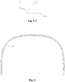
- FIG. 5-1 and FIG. 5-2 are respectively partial enlarged views of positions 11 and 12 in FIG. 4
- FIG.6 is a cross-sectional view of an annular beam of a rail vehicle body structure provided by a specific embodiment of the present application
- FIG. 1 is a cross-sectional view of a rail vehicle body structure provided by a specific embodiment of the present application
- FIG. 2 is a partial enlarged view of position A in FIG. 1
- FIG. 3 is a cross-sectional view of the skin of the rail vehicle body structure provided by a specific embodiment
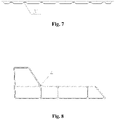
- FIG. 7 is a cross-sectional view of an underframe cross beam of a rail vehicle body structure provided by a specific embodiment of the present application
- FIG. 8 is a cross-sectional view of an underframe side beam of a rail vehicle body structure provided by a specific embodiment of the present application.
- the rail vehicle body structure includes a cylindrical corrugated plate 1; an annular beam 2 and an underframe cross beam 3 nested inside the corrugated plate 1; and an underframe side beam 4 arranged between the annular beam 2 and the underframe cross beam 3; a pair of interface parts 12 are symmetrically arranged on both sides of the bottom of the corrugated plate 1, and the underframe side beams 4 are arranged outside the pair of interface parts 12.
- a connecting plate 6 is provided on an inner side of the bottom of the rail vehicle body structure.
- the annular beam 2 is connected with the connecting plate 6 by rivets or bolts, and the underframe side beam 4, the corrugated plate 1 and the connecting plate 6 are connected by rivets or bolts, and a sealant may be applied between the annular beam 2 and the connecting plate 6 and between the underframe side beam 4, the corrugated plate 1 and the connecting plate 6 at the same time.
- a skin 5 is laid outside the corrugated plate 1 and the underframe side beam 4.
- the corrugated plate 1 is provided with multiple ribs 11, and the positions of the ribs 11 may be determined according to the interior decoration, equipment interface and strength requirements.
- the annular beam 2 and the underframe cross beam 3 are used for improving the rigidity and strength of the vehicle body.
- the annular beam 2 is provided with a rib passage notch 21 at a position corresponding to each of the multiple ribs 11, and the underframe cross beam 3 is provided with a rib passage notch 31 at a position corresponding to the rib 11.
- An equipment mounting part 7 is riveted on the underframe side beam 4, and the equipment mounting part 7 is provided with a sliding groove 71 for providing the equipment interface, and the shape of the sliding groove 71 may be varied according to specific requirements.
- the corrugated plate 1, the annular beam 2, the underframe cross beam 3, the underframe side beam 4 and the skin 5 are all made of carbon fiber composite materials.
- the rail vehicle body structure provided by the present application is a cylindrical integrally-formed structure, and the skin 5 and the corrugated plate 1 are integrally formed by adopting an automatic laying technology, and the underframe side beam 4 is arranged between the skin 5 and the corrugated plate 1, and the connection strength is high.
- the manufacturing process of the rail vehicle body structure is as follows: pre-forming the cylindrical corrugated plate 1 by the automatic laying technology, and after the pre-forming, placing a sandwich material (the sandwich material may be foam or paper honeycomb) at the rib 11, and placing the underframe side beam 4 at each of two sides, and then automatically laying the skin 5 at an outside, and then performing an integral curing and formation, finally, placing the annular beam 2 and the underframe cross beam 3, and finally performing a secondary curing.
- a sandwich material the sandwich material may be foam or paper honeycomb
Landscapes
- Engineering & Computer Science (AREA)
- Mechanical Engineering (AREA)
- Life Sciences & Earth Sciences (AREA)
- Wood Science & Technology (AREA)
- Body Structure For Vehicles (AREA)
- Laminated Bodies (AREA)
Abstract
Description
- The present application claims the priority to
Chinese Patent Application No. 201910542773.5, titled "RAIL VEHICLE BODY STRUCTURE", filed with the China National Intellectual Property Administration on June 21, 2019 - The present application relates to the technical field of rail vehicles, and in particular to a body structure of a rail vehicle.
- With the continuous increase of the rail transit speed, a series of problems such as high resistance, high energy consumption, high vibration and high noise have been brought to the train. To solve these problems, it is necessary to improve the strength and optimize the structure of a train on the basis of lightweight. The traditional metal material vehicle body structure has limited lifting space to solve the above problem. Thus, new lighter and stronger material is required.
- In addition, the existing vehicle body structure of the rail vehicle has many modules and a large assembly amount, and a large number of modules are connected by rivets, the processing amount of the rivet holes is large and it is easy to leak rain; a large number of metal connectors are used, and the weight is increased.
- Therefore, how to provide a rail vehicle body structure with a high degree of lightness, a small number of parts, and a greatly reduced assembly volume is an important technical problem to be solved by those skilled in the art.
- In order to solve the above technical problems, the present application provides a rail vehicle body structure, the rail vehicle body structure has a high degree of lightweight and a small number of parts and may greatly reduce the amount of assembly.
- In order to solve the above technical problems, the present application provides a rail vehicle body structure, the rail vehicle body structure includes a cylindrical corrugated plate;
- an annular beam and an underframe cross beam sleeved inside the corrugated plate; and,
- an underframe side beam arranged between the annular beam and the underframe cross beam;
- a pair of interface parts are symmetrically arranged on both sides of a bottom of the corrugated plate, and the underframe side beam is arranged outside the pair of interface parts.
- Optionally, a connecting plate is provided on an inner side of a bottom of the rail vehicle body structure.
- Optionally, the annular beam and the connecting plate are connected by rivets or bolts, and the underframe side beam, the corrugated plate and the connecting plate are connected by rivets or bolts.
- Optionally, a sealant is coated between the annular beam and the connecting plate, and between the underframe side beam, the corrugated plate and the connecting plate.
- Optionally, a skin is laid on an outside of the corrugated plate and the underframe side beam.
- Optionally, multiple ribs are provided on the corrugated plate.
- Optionally, the annular beam and the underframe cross beam are provided with a rib passage notch at a positions corresponding to each of the multiple ribs.
- Optionally, the underframe side beam is riveted with an equipment mounting part, and the equipment mounting part is provided with a sliding groove.
- Optionally, the corrugated plate, the annular beam, the underframe cross beam, the underframe side beam and the skin are all made of carbon fiber composite materials.
- Compared with the above background technology, the rail vehicle body structure provided by the present application has the following beneficial effects:
- 1. using carbon fiber composite materials, the vehicle body is light in weight.
- 2. the cross-section is a cylindrical overall structure with no joints and good air tightness.
- 3. the cylindrical overall structure has a high degree of automation during manufacture and high production efficiency.
- 4. the number of parts is small and the assembly volume is low.
-
-
FIG. 1 is a cross-sectional view of a rail vehicle body structure provided by a specific embodiment of the present application; -
FIG. 2 is a partial enlarged view of position A inFIG. 1 ; -
FIG. 3 is a cross-sectional view of the skin of the rail vehicle body structure provided by a specific embodiment of the present application; -
FIG. 4 is a cross-sectional view of a corrugated plate of a rail vehicle body structure provided by a specific embodiment of the present application; -
FIG. 5-1 andFIG. 5-2 are respectively partial enlarged views ofpositions FIG. 4 ; -
FIG. 6 is a cross-sectional view of an annular beam of a rail vehicle body structure provided by a specific embodiment of the present application; -
FIG. 7 is a cross-sectional view of an underframe cross beam of a rail vehicle body structure provided by a specific embodiment of the present application; -
FIG. 8 is a cross-sectional view of an underframe side beam of a rail vehicle body structure provided by a specific embodiment of the present application. - Reference numerals are listed as follows,
1 corrugated plate; 11 rib; 12 interface part; 2 annular beam; 3 underframe cross beam; 21, 31 rib passage notch; 4 underframe side beam; 5 skin; 6 connecting plate; 7 equipment mounting part; 71 sliding groove. - In order to provide those skilled in the art a better understanding of the solutions of the present application, the present application is described hereinafter in further detail in conjunction with the drawings and embodiments.
- In the description of the present application, it is to be understood that the orientation or positional relationships indicated by terms "center", "longitudinal", "lateral", "length", "width", "thickness", "up", "down", "front", "rear", "left", "right", "vertical", "horizontal", "top", "bottom", "inner", "outer", "clockwise", "anticlockwise" and the like are based on the orientation or positional relationships shown in the drawings, and are merely for the convenience of describing the present application and the simplification of the description, and do not indicate or imply that the device or member referred to must be in a particular orientation, or be constructed and operated in a particular orientation, and therefore should not be construed as a limitation to the scope of the present application.
- In addition, the terms "first", "second" and the like are for purpose of description, and should not be interpreted as indicating or implying relative importance or implying the number of the indicated technical features. Therefore, the features defined by "first" and "second" may explicitly or implicitly include one or more of the features. In the description of the present disclosure, the meaning of "multiple" is two or more, unless specifically defined otherwise.
- In the description of the present application, it should be pointed out that, terms "install", "link", "connect" and "fix" should be understood broadly, unless otherwise specifically defined. For example, it can be fixedly connected or detachably connected or integrally connected; it can be mechanically connected or electrically connected; it can be directly connected or indirectly connected through intermediate media, or inner parts of two components are in communication with each other. For those skilled in the art, the specific meaning of the above terms in the present application may be understood in the light of specific circumstances.
- A core of the present application is to provide a rail vehicle body structure. The rail vehicle body structure has a high degree of lightweight, a small number of parts, and may greatly reduce the amount of assembly.
- In order to provide those skilled in the art with a better understanding of the solutions of the present application, the present application will be described hereinafter in further detail in conjunction with the drawings and specific embodiments.
- Referring to
FIG.1 to FIG.8 ,FIG. 1 is a cross-sectional view of a rail vehicle body structure provided by a specific embodiment of the present application;FIG. 2 is a partial enlarged view of position A inFIG. 1 ;FIG. 3 is a cross-sectional view of the skin of the rail vehicle body structure provided by a specific embodiment of the present application;FIG. 4 is a cross-sectional view of a corrugated plate of a rail vehicle body structure provided by a specific embodiment of the present application;FIG. 5-1 andFIG. 5-2 are respectively partial enlarged views ofpositions FIG. 4 ;FIG.6 is a cross-sectional view of an annular beam of a rail vehicle body structure provided by a specific embodiment of the present application;FIG. 7 is a cross-sectional view of an underframe cross beam of a rail vehicle body structure provided by a specific embodiment of the present application;FIG. 8 is a cross-sectional view of an underframe side beam of a rail vehicle body structure provided by a specific embodiment of the present application. - In a specific embodiment, the rail vehicle body structure provided by the present application includes a cylindrical corrugated plate 1; an annular beam 2 and an
underframe cross beam 3 nested inside the corrugated plate 1; and anunderframe side beam 4 arranged between the annular beam 2 and theunderframe cross beam 3; a pair ofinterface parts 12 are symmetrically arranged on both sides of the bottom of the corrugated plate 1, and theunderframe side beams 4 are arranged outside the pair ofinterface parts 12. - In the rail vehicle body structure provided by the present application, a connecting
plate 6 is provided on an inner side of the bottom of the rail vehicle body structure. The annular beam 2 is connected with the connectingplate 6 by rivets or bolts, and theunderframe side beam 4, the corrugated plate 1 and theconnecting plate 6 are connected by rivets or bolts, and a sealant may be applied between the annular beam 2 and the connectingplate 6 and between theunderframe side beam 4, the corrugated plate 1 and the connectingplate 6 at the same time. Askin 5 is laid outside the corrugated plate 1 and theunderframe side beam 4. The corrugated plate 1 is provided withmultiple ribs 11, and the positions of theribs 11 may be determined according to the interior decoration, equipment interface and strength requirements. The annular beam 2 and theunderframe cross beam 3 are used for improving the rigidity and strength of the vehicle body. The annular beam 2 is provided with arib passage notch 21 at a position corresponding to each of themultiple ribs 11, and theunderframe cross beam 3 is provided with arib passage notch 31 at a position corresponding to therib 11. Anequipment mounting part 7 is riveted on theunderframe side beam 4, and theequipment mounting part 7 is provided with asliding groove 71 for providing the equipment interface, and the shape of thesliding groove 71 may be varied according to specific requirements. The corrugated plate 1, the annular beam 2, theunderframe cross beam 3, theunderframe side beam 4 and theskin 5 are all made of carbon fiber composite materials. - The rail vehicle body structure provided by the present application is a cylindrical integrally-formed structure, and the
skin 5 and the corrugated plate 1 are integrally formed by adopting an automatic laying technology, and theunderframe side beam 4 is arranged between theskin 5 and the corrugated plate 1, and the connection strength is high. - The manufacturing process of the rail vehicle body structure provided by the present application is as follows: pre-forming the cylindrical corrugated plate 1 by the automatic laying technology, and after the pre-forming, placing a sandwich material (the sandwich material may be foam or paper honeycomb) at the
rib 11, and placing theunderframe side beam 4 at each of two sides, and then automatically laying theskin 5 at an outside, and then performing an integral curing and formation, finally, placing the annular beam 2 and theunderframe cross beam 3, and finally performing a secondary curing. - The above embodiments are only preferred embodiments of the present application. It should be noted that, for those skilled in the art, other improvements and modifications may be further made without departing from the principle of the present application, and these improvements and modifications should also be deemed as falling into the protection scope of the present application.
Claims (9)
- A rail vehicle body structure, comprising a cylindrical corrugated plate;an annular beam and an underframe cross beam sleeved inside the corrugated plate; and,an underframe side beam arranged between the annular beam and the underframe cross beam;a pair of interface parts are symmetrically arranged on both sides of a bottom of the corrugated plate , and the underframe side beam is arranged outside each of the pair of interface parts.
- The rail vehicle body structure according to claim 1, wherein a connecting plate is provided on an inner side of a bottom of the rail vehicle body structure.
- The rail vehicle body structure according to claim 2, wherein the annular beam and the connecting plate are connected by rivets or bolts, and the underframe side beam, the corrugated plate and the connecting plate are connected by rivets or bolts.
- The rail vehicle body structure according to claim 2 or claim 3, wherein a sealant is coated between the annular beam and the connecting plate, and between the underframe side beam, the corrugated plate and the connecting plate.
- The rail vehicle body structure according to claim 1, wherein a skin is laid on an outside of the corrugated plate and the underframe side beam.
- The rail vehicle body structure according to claim 1, wherein a plurality of ribs are provided on the corrugated plate.
- The rail vehicle body structure according to claim 6, wherein the annular beam and the underframe cross beam are provided with a rib passage notch at a position corresponding to each of the plurality of ribs.
- The rail vehicle body structure according to claim 1, wherein the underframe side beam is riveted with an equipment mounting part, and the equipment mounting part is provided with a sliding groove.
- The rail vehicle body structure according to claim 5, wherein the corrugated plate, the annular beam, the underframe cross beam, the underframe side beam and the skin are all made of carbon fiber composite materials.
Applications Claiming Priority (2)
| Application Number | Priority Date | Filing Date | Title |
|---|---|---|---|
| CN201910542773.5A CN110281962B (en) | 2019-06-21 | 2019-06-21 | A body structure of a rail vehicle |
| PCT/CN2020/086012 WO2020253356A1 (en) | 2019-06-21 | 2020-04-22 | Rail vehicle body structure |
Publications (3)
| Publication Number | Publication Date |
|---|---|
| EP3988418A1 true EP3988418A1 (en) | 2022-04-27 |
| EP3988418A4 EP3988418A4 (en) | 2023-08-02 |
| EP3988418B1 EP3988418B1 (en) | 2025-11-12 |
Family
ID=68005370
Family Applications (1)
| Application Number | Title | Priority Date | Filing Date |
|---|---|---|---|
| EP20825540.6A Active EP3988418B1 (en) | 2019-06-21 | 2020-04-22 | Rail vehicle body structure |
Country Status (6)
| Country | Link |
|---|---|
| US (1) | US20220009529A1 (en) |
| EP (1) | EP3988418B1 (en) |
| CN (1) | CN110281962B (en) |
| CA (1) | CA3118768C (en) |
| ES (1) | ES3058228T3 (en) |
| WO (1) | WO2020253356A1 (en) |
Families Citing this family (2)
| Publication number | Priority date | Publication date | Assignee | Title |
|---|---|---|---|---|
| CN110281962B (en) * | 2019-06-21 | 2020-10-02 | 中车青岛四方机车车辆股份有限公司 | A body structure of a rail vehicle |
| CN113479226B (en) * | 2021-02-07 | 2022-05-31 | 常州市新创智能科技有限公司 | Carbon fiber composite material underframe structure of vehicle body of high-speed rail transit motor train unit |
Family Cites Families (25)
| Publication number | Priority date | Publication date | Assignee | Title |
|---|---|---|---|---|
| DE627722C (en) * | 1930-02-08 | 1936-04-14 | Heinrich Croseck Dipl Ing | Vehicle for railways |
| US2223746A (en) * | 1938-09-03 | 1940-12-03 | Pacific Railway Equipment Comp | Vehicle body construction |
| US2294357A (en) * | 1940-05-18 | 1942-08-25 | Budd Edward G Mfg Co | Vehicle body construction |
| US2595212A (en) * | 1945-01-15 | 1952-04-29 | Budd Co | Vehicle body, especially for rail cars |
| DE2712752A1 (en) * | 1977-03-23 | 1978-09-28 | Daimler Benz Ag | Modular construction bus body - has corrugated main support cut to shape to relieve sectioned outer panels and inner skin |
| US4222335A (en) * | 1978-08-22 | 1980-09-16 | The Budd Company | Means for manufacturing a modular railway car |
| IT1118723B (en) * | 1979-05-24 | 1986-03-03 | Fiat Ricerche | CASE FOR RAILWAY CARRIAGES |
| DE3838686C2 (en) * | 1988-11-15 | 1993-10-21 | Man Ghh Schienenverkehr | Vehicle compartment |
| US5267515A (en) * | 1989-01-18 | 1993-12-07 | Hitachi, Ltd. | Vehicle body construction having longitudinally elongated extruded panels and continuous welds joining the panels |
| US5287814A (en) * | 1989-04-14 | 1994-02-22 | Hitachi, Ltd. | Car body of railway rolling stock and method for fabricating car body |
| US5433151A (en) * | 1990-09-07 | 1995-07-18 | Hitachi, Ltd. | Railway car body structures and methods of making them using welded honeycomb panels connected in an edge to edge relation |
| JPH05213189A (en) * | 1992-02-04 | 1993-08-24 | Railway Technical Res Inst | Vehicle body structure |
| JP2934582B2 (en) * | 1994-09-13 | 1999-08-16 | 株式会社日立製作所 | Railcar structure |
| US6092472A (en) * | 1996-07-19 | 2000-07-25 | Trn Business Trust | Composite box structure for a railway car |
| SE0002138L (en) * | 2000-06-07 | 2001-12-08 | Bombardier Transp Gmbh | Trolley housing of a railroad vehicle |
| US7000978B1 (en) * | 2004-08-20 | 2006-02-21 | Frank Messano | Thin-skin ultralight recreational vehicle body system |
| AT503255A3 (en) * | 2006-03-06 | 2010-05-15 | Siemens Ag Oesterreich | RAIL VEHICLE WITH A BASE |
| CN102066178B (en) * | 2009-06-10 | 2016-01-13 | 川崎重工业株式会社 | The Enhancement Method of railroad vehicle body structure and railroad vehicle body structure |
| CN203681555U (en) * | 2014-01-07 | 2014-07-02 | 南车株洲电力机车有限公司 | Car body structure of rail car |
| KR101608429B1 (en) * | 2014-10-27 | 2016-04-04 | 한국철도기술연구원 | A railway vehicle body made of non-framable magnesium alloy |
| CN204355053U (en) * | 2014-12-18 | 2015-05-27 | 南车青岛四方机车车辆股份有限公司 | Motor train unit and outer hood thereof |
| CN205469074U (en) * | 2015-11-24 | 2016-08-17 | 中车青岛四方机车车辆股份有限公司 | Rail train , automobile body and equipment compartment thereof |
| CN105416320B (en) * | 2015-12-09 | 2018-08-03 | 南车株洲电力机车有限公司 | A kind of lightweight tramcar body construction, vehicle group and manufacturing method |
| CN106394574A (en) * | 2016-08-31 | 2017-02-15 | 中车青岛四方机车车辆股份有限公司 | Corrugated plate and railway vehicle with same |
| CN110281962B (en) * | 2019-06-21 | 2020-10-02 | 中车青岛四方机车车辆股份有限公司 | A body structure of a rail vehicle |
-
2019
- 2019-06-21 CN CN201910542773.5A patent/CN110281962B/en active Active
-
2020
- 2020-04-22 CA CA3118768A patent/CA3118768C/en active Active
- 2020-04-22 ES ES20825540T patent/ES3058228T3/en active Active
- 2020-04-22 WO PCT/CN2020/086012 patent/WO2020253356A1/en not_active Ceased
- 2020-04-22 EP EP20825540.6A patent/EP3988418B1/en active Active
- 2020-04-22 US US17/288,533 patent/US20220009529A1/en not_active Abandoned
Also Published As
| Publication number | Publication date |
|---|---|
| CN110281962A (en) | 2019-09-27 |
| EP3988418A4 (en) | 2023-08-02 |
| US20220009529A1 (en) | 2022-01-13 |
| CN110281962B (en) | 2020-10-02 |
| EP3988418B1 (en) | 2025-11-12 |
| ES3058228T3 (en) | 2026-03-09 |
| CA3118768A1 (en) | 2020-12-24 |
| CA3118768C (en) | 2023-09-05 |
| WO2020253356A1 (en) | 2020-12-24 |
Similar Documents
| Publication | Publication Date | Title |
|---|---|---|
| CN107901938B (en) | The pillow pulling buffering apparatus of full aluminium rail vehicle | |
| EP4385858A1 (en) | Lower vehicle body middle structure and vehicle | |
| CN211519498U (en) | Spliced car body and rail vehicle | |
| CA3118768C (en) | Rail vehicle body structure | |
| CN105197031A (en) | Rail car and side wall assembly thereof | |
| WO2019100719A1 (en) | Control car chassis and control car | |
| CN202657036U (en) | Bottom frame edge beam of motor train unit and motor train unit body | |
| CN113954887B (en) | Rail vehicle | |
| CN103802848A (en) | Hood structure of high speed train headstock and installation method | |
| CN116691998A (en) | Aircraft windshield window frame skeleton subassembly | |
| CN211731598U (en) | Longitudinal beam rear section connecting structure | |
| EP4086133A1 (en) | Assembly-type car body and rail vehicle | |
| CN218537084U (en) | Wing body connecting reinforcing frame | |
| CN209581491U (en) | A kind of air-conditioning installing frame of rail vehicle | |
| CN218198267U (en) | Rail vehicle and roof structure | |
| CN110281963A (en) | A body structure of a rail vehicle | |
| CN204870480U (en) | Car back door inner panel and car back door | |
| CN113022610B (en) | Floor composition for magnetic levitation vehicle and magnetic levitation vehicle | |
| CN210793180U (en) | Novel lightweight air duct | |
| CN115447792A (en) | Air inlet with airplane composite material integrally-formed lip | |
| CN218805798U (en) | Intelligent prepreg honeycomb middle top plate of motor train unit | |
| CN221393687U (en) | Cross beam assembly of chassis frame, chassis frame and vehicle | |
| EP3741641A1 (en) | Locomotive structure for electric multiple unit | |
| CN207773238U (en) | Frame cross assembly | |
| CN207089418U (en) | Carbon fiber rear auxiliary frame and vehicle with same |
Legal Events
| Date | Code | Title | Description |
|---|---|---|---|
| STAA | Information on the status of an ep patent application or granted ep patent |
Free format text: STATUS: THE INTERNATIONAL PUBLICATION HAS BEEN MADE |
|
| PUAI | Public reference made under article 153(3) epc to a published international application that has entered the european phase |
Free format text: ORIGINAL CODE: 0009012 |
|
| STAA | Information on the status of an ep patent application or granted ep patent |
Free format text: STATUS: REQUEST FOR EXAMINATION WAS MADE |
|
| 17P | Request for examination filed |
Effective date: 20210514 |
|
| AK | Designated contracting states |
Kind code of ref document: A1 Designated state(s): AL AT BE BG CH CY CZ DE DK EE ES FI FR GB GR HR HU IE IS IT LI LT LU LV MC MK MT NL NO PL PT RO RS SE SI SK SM TR |
|
| DAV | Request for validation of the european patent (deleted) | ||
| DAX | Request for extension of the european patent (deleted) | ||
| A4 | Supplementary search report drawn up and despatched |
Effective date: 20230703 |
|
| RIC1 | Information provided on ipc code assigned before grant |
Ipc: B62D 31/00 20060101ALI20230627BHEP Ipc: B61D 17/04 20060101AFI20230627BHEP |
|
| RIN1 | Information on inventor provided before grant (corrected) |
Inventor name: TIAN, AIQIN Inventor name: WANG, WANJING Inventor name: ZHANG, LIANHE Inventor name: LIANG, HAITING Inventor name: DING, SANSAN |
|
| GRAP | Despatch of communication of intention to grant a patent |
Free format text: ORIGINAL CODE: EPIDOSNIGR1 |
|
| STAA | Information on the status of an ep patent application or granted ep patent |
Free format text: STATUS: GRANT OF PATENT IS INTENDED |
|
| INTG | Intention to grant announced |
Effective date: 20250611 |
|
| RIC1 | Information provided on ipc code assigned before grant |
Ipc: B62D 31/00 20060101ALI20250530BHEP Ipc: B61D 17/04 20060101AFI20250530BHEP |
|
| GRAS | Grant fee paid |
Free format text: ORIGINAL CODE: EPIDOSNIGR3 |
|
| GRAA | (expected) grant |
Free format text: ORIGINAL CODE: 0009210 |
|
| STAA | Information on the status of an ep patent application or granted ep patent |
Free format text: STATUS: THE PATENT HAS BEEN GRANTED |
|
| AK | Designated contracting states |
Kind code of ref document: B1 Designated state(s): AL AT BE BG CH CY CZ DE DK EE ES FI FR GB GR HR HU IE IS IT LI LT LU LV MC MK MT NL NO PL PT RO RS SE SI SK SM TR |
|
| REG | Reference to a national code |
Ref country code: CH Ref legal event code: F10 Free format text: ST27 STATUS EVENT CODE: U-0-0-F10-F00 (AS PROVIDED BY THE NATIONAL OFFICE) Effective date: 20251112 Ref country code: GB Ref legal event code: FG4D |
|
| REG | Reference to a national code |
Ref country code: IE Ref legal event code: FG4D |
|
| REG | Reference to a national code |
Ref country code: DE Ref legal event code: R096 Ref document number: 602020062190 Country of ref document: DE |
|
| REG | Reference to a national code |
Ref country code: CH Ref legal event code: W10 Free format text: ST27 STATUS EVENT CODE: U-0-0-W10-W00 (AS PROVIDED BY THE NATIONAL OFFICE) Effective date: 20251217 |
|
| RAP4 | Party data changed (patent owner data changed or rights of a patent transferred) |
Owner name: CRRC QINGDAO SIFANG CO., LTD. |
|
| REG | Reference to a national code |
Ref country code: ES Ref legal event code: FG2A Ref document number: 3058228 Country of ref document: ES Kind code of ref document: T3 Effective date: 20260309 |
|
| REG | Reference to a national code |
Ref country code: NL Ref legal event code: MP Effective date: 20251112 |
|
| PGFP | Annual fee paid to national office [announced via postgrant information from national office to epo] |
Ref country code: GB Payment date: 20260325 Year of fee payment: 7 |
|
| REG | Reference to a national code |
Ref country code: LT Ref legal event code: MG9D |
|
| PG25 | Lapsed in a contracting state [announced via postgrant information from national office to epo] |
Ref country code: NO Free format text: LAPSE BECAUSE OF FAILURE TO SUBMIT A TRANSLATION OF THE DESCRIPTION OR TO PAY THE FEE WITHIN THE PRESCRIBED TIME-LIMIT Effective date: 20260212 |
|
| PG25 | Lapsed in a contracting state [announced via postgrant information from national office to epo] |
Ref country code: HR Free format text: LAPSE BECAUSE OF FAILURE TO SUBMIT A TRANSLATION OF THE DESCRIPTION OR TO PAY THE FEE WITHIN THE PRESCRIBED TIME-LIMIT Effective date: 20251112 Ref country code: AT Free format text: LAPSE BECAUSE OF FAILURE TO SUBMIT A TRANSLATION OF THE DESCRIPTION OR TO PAY THE FEE WITHIN THE PRESCRIBED TIME-LIMIT Effective date: 20251112 Ref country code: FI Free format text: LAPSE BECAUSE OF FAILURE TO SUBMIT A TRANSLATION OF THE DESCRIPTION OR TO PAY THE FEE WITHIN THE PRESCRIBED TIME-LIMIT Effective date: 20251112 |
|
| REG | Reference to a national code |
Ref country code: AT Ref legal event code: MK05 Ref document number: 1856531 Country of ref document: AT Kind code of ref document: T Effective date: 20251112 |
|
| PG25 | Lapsed in a contracting state [announced via postgrant information from national office to epo] |
Ref country code: NL Free format text: LAPSE BECAUSE OF FAILURE TO SUBMIT A TRANSLATION OF THE DESCRIPTION OR TO PAY THE FEE WITHIN THE PRESCRIBED TIME-LIMIT Effective date: 20251112 |
|
| PG25 | Lapsed in a contracting state [announced via postgrant information from national office to epo] |
Ref country code: RS Free format text: LAPSE BECAUSE OF FAILURE TO SUBMIT A TRANSLATION OF THE DESCRIPTION OR TO PAY THE FEE WITHIN THE PRESCRIBED TIME-LIMIT Effective date: 20260212 |
|
| PG25 | Lapsed in a contracting state [announced via postgrant information from national office to epo] |
Ref country code: IS Free format text: LAPSE BECAUSE OF FAILURE TO SUBMIT A TRANSLATION OF THE DESCRIPTION OR TO PAY THE FEE WITHIN THE PRESCRIBED TIME-LIMIT Effective date: 20260312 |
|
| PGFP | Annual fee paid to national office [announced via postgrant information from national office to epo] |
Ref country code: FR Payment date: 20260325 Year of fee payment: 7 |
|
| PG25 | Lapsed in a contracting state [announced via postgrant information from national office to epo] |
Ref country code: PT Free format text: LAPSE BECAUSE OF FAILURE TO SUBMIT A TRANSLATION OF THE DESCRIPTION OR TO PAY THE FEE WITHIN THE PRESCRIBED TIME-LIMIT Effective date: 20260312 |
|
| PG25 | Lapsed in a contracting state [announced via postgrant information from national office to epo] |
Ref country code: PL Free format text: LAPSE BECAUSE OF FAILURE TO SUBMIT A TRANSLATION OF THE DESCRIPTION OR TO PAY THE FEE WITHIN THE PRESCRIBED TIME-LIMIT Effective date: 20251112 |
|
| PG25 | Lapsed in a contracting state [announced via postgrant information from national office to epo] |
Ref country code: LV Free format text: LAPSE BECAUSE OF FAILURE TO SUBMIT A TRANSLATION OF THE DESCRIPTION OR TO PAY THE FEE WITHIN THE PRESCRIBED TIME-LIMIT Effective date: 20251112 |
|
| PG25 | Lapsed in a contracting state [announced via postgrant information from national office to epo] |
Ref country code: BG Free format text: LAPSE BECAUSE OF FAILURE TO SUBMIT A TRANSLATION OF THE DESCRIPTION OR TO PAY THE FEE WITHIN THE PRESCRIBED TIME-LIMIT Effective date: 20251112 |