EP3988198A1 - Device and process for adjusting the equipment of a facility for producing biomethane - Google Patents
Device and process for adjusting the equipment of a facility for producing biomethane Download PDFInfo
- Publication number
- EP3988198A1 EP3988198A1 EP21202983.9A EP21202983A EP3988198A1 EP 3988198 A1 EP3988198 A1 EP 3988198A1 EP 21202983 A EP21202983 A EP 21202983A EP 3988198 A1 EP3988198 A1 EP 3988198A1
- Authority
- EP
- European Patent Office
- Prior art keywords
- datum
- membrane separation
- installation
- flow
- biogas
- Prior art date
- Legal status (The legal status is an assumption and is not a legal conclusion. Google has not performed a legal analysis and makes no representation as to the accuracy of the status listed.)
- Granted
Links
Images

Classifications
-
- B—PERFORMING OPERATIONS; TRANSPORTING
- B01—PHYSICAL OR CHEMICAL PROCESSES OR APPARATUS IN GENERAL
- B01D—SEPARATION
- B01D53/00—Separation of gases or vapours; Recovering vapours of volatile solvents from gases; Chemical or biological purification of waste gases, e.g. engine exhaust gases, smoke, fumes, flue gases, aerosols
- B01D53/22—Separation of gases or vapours; Recovering vapours of volatile solvents from gases; Chemical or biological purification of waste gases, e.g. engine exhaust gases, smoke, fumes, flue gases, aerosols by diffusion
- B01D53/225—Multiple stage diffusion
- B01D53/227—Multiple stage diffusion in parallel connexion
-
- B—PERFORMING OPERATIONS; TRANSPORTING
- B01—PHYSICAL OR CHEMICAL PROCESSES OR APPARATUS IN GENERAL
- B01D—SEPARATION
- B01D53/00—Separation of gases or vapours; Recovering vapours of volatile solvents from gases; Chemical or biological purification of waste gases, e.g. engine exhaust gases, smoke, fumes, flue gases, aerosols
- B01D53/002—Separation of gases or vapours; Recovering vapours of volatile solvents from gases; Chemical or biological purification of waste gases, e.g. engine exhaust gases, smoke, fumes, flue gases, aerosols by condensation
-
- B—PERFORMING OPERATIONS; TRANSPORTING
- B01—PHYSICAL OR CHEMICAL PROCESSES OR APPARATUS IN GENERAL
- B01D—SEPARATION
- B01D53/00—Separation of gases or vapours; Recovering vapours of volatile solvents from gases; Chemical or biological purification of waste gases, e.g. engine exhaust gases, smoke, fumes, flue gases, aerosols
- B01D53/30—Controlling by gas-analysis apparatus
-
- C—CHEMISTRY; METALLURGY
- C10—PETROLEUM, GAS OR COKE INDUSTRIES; TECHNICAL GASES CONTAINING CARBON MONOXIDE; FUELS; LUBRICANTS; PEAT
- C10L—FUELS NOT OTHERWISE PROVIDED FOR; NATURAL GAS; SYNTHETIC NATURAL GAS OBTAINED BY PROCESSES NOT COVERED BY SUBCLASSES C10G OR C10K; LIQUIFIED PETROLEUM GAS; USE OF ADDITIVES TO FUELS OR FIRES; FIRE-LIGHTERS
- C10L3/00—Gaseous fuels; Natural gas; Synthetic natural gas obtained by processes not covered by subclass C10G, C10K; Liquefied petroleum gas
- C10L3/06—Natural gas; Synthetic natural gas obtained by processes not covered by C10G, C10K3/02 or C10K3/04
- C10L3/10—Working-up natural gas or synthetic natural gas
- C10L3/101—Removal of contaminants
- C10L3/102—Removal of contaminants of acid contaminants
- C10L3/104—Carbon dioxide
-
- B—PERFORMING OPERATIONS; TRANSPORTING
- B01—PHYSICAL OR CHEMICAL PROCESSES OR APPARATUS IN GENERAL
- B01D—SEPARATION
- B01D2256/00—Main component in the product gas stream after treatment
- B01D2256/24—Hydrocarbons
- B01D2256/245—Methane
-
- B—PERFORMING OPERATIONS; TRANSPORTING
- B01—PHYSICAL OR CHEMICAL PROCESSES OR APPARATUS IN GENERAL
- B01D—SEPARATION
- B01D2257/00—Components to be removed
- B01D2257/50—Carbon oxides
- B01D2257/504—Carbon dioxide
-
- B—PERFORMING OPERATIONS; TRANSPORTING
- B01—PHYSICAL OR CHEMICAL PROCESSES OR APPARATUS IN GENERAL
- B01D—SEPARATION
- B01D2258/00—Sources of waste gases
- B01D2258/05—Biogas
-
- C—CHEMISTRY; METALLURGY
- C10—PETROLEUM, GAS OR COKE INDUSTRIES; TECHNICAL GASES CONTAINING CARBON MONOXIDE; FUELS; LUBRICANTS; PEAT
- C10L—FUELS NOT OTHERWISE PROVIDED FOR; NATURAL GAS; SYNTHETIC NATURAL GAS OBTAINED BY PROCESSES NOT COVERED BY SUBCLASSES C10G OR C10K; LIQUIFIED PETROLEUM GAS; USE OF ADDITIVES TO FUELS OR FIRES; FIRE-LIGHTERS
- C10L2290/00—Fuel preparation or upgrading, processes or apparatus therefore, comprising specific process steps or apparatus units
- C10L2290/54—Specific separation steps for separating fractions, components or impurities during preparation or upgrading of a fuel
- C10L2290/548—Membrane- or permeation-treatment for separating fractions, components or impurities during preparation or upgrading of a fuel
-
- Y—GENERAL TAGGING OF NEW TECHNOLOGICAL DEVELOPMENTS; GENERAL TAGGING OF CROSS-SECTIONAL TECHNOLOGIES SPANNING OVER SEVERAL SECTIONS OF THE IPC; TECHNICAL SUBJECTS COVERED BY FORMER USPC CROSS-REFERENCE ART COLLECTIONS [XRACs] AND DIGESTS
- Y02—TECHNOLOGIES OR APPLICATIONS FOR MITIGATION OR ADAPTATION AGAINST CLIMATE CHANGE
- Y02C—CAPTURE, STORAGE, SEQUESTRATION OR DISPOSAL OF GREENHOUSE GASES [GHG]
- Y02C20/00—Capture or disposal of greenhouse gases
- Y02C20/40—Capture or disposal of greenhouse gases of CO2
-
- Y—GENERAL TAGGING OF NEW TECHNOLOGICAL DEVELOPMENTS; GENERAL TAGGING OF CROSS-SECTIONAL TECHNOLOGIES SPANNING OVER SEVERAL SECTIONS OF THE IPC; TECHNICAL SUBJECTS COVERED BY FORMER USPC CROSS-REFERENCE ART COLLECTIONS [XRACs] AND DIGESTS
- Y02—TECHNOLOGIES OR APPLICATIONS FOR MITIGATION OR ADAPTATION AGAINST CLIMATE CHANGE
- Y02E—REDUCTION OF GREENHOUSE GAS [GHG] EMISSIONS, RELATED TO ENERGY GENERATION, TRANSMISSION OR DISTRIBUTION
- Y02E50/00—Technologies for the production of fuel of non-fossil origin
- Y02E50/30—Fuel from waste, e.g. synthetic alcohol or diesel
Definitions
- the present invention relates to the field of the purification of biogas into biomethane by a process of membrane permeation, in particular the purification of biogas with the aim of producing biomethane in conformity with the specifications for injection into a natural gas network.
- Biogas is the gas produced during the degradation of organic matter in the absence of oxygen (anaerobic fermentation) also called methanation. It can be a natural degradation - it can thus be observed in marshes or household waste dumps - but the production of biogas can also result from the methanization of waste in a dedicated reactor, called a methanizer or digester.
- Biogas Due to its main constituents - methane and carbon dioxide - biogas is a powerful greenhouse gas; it also constitutes, at the same time, an appreciable source of renewable energy in a context of scarcity of fossil fuels.
- Biogas mainly contains methane (CH 4 ) and carbon dioxide (CO 2 ) in varying proportions depending on the mode of production but also, in smaller proportions, water, nitrogen, hydrogen sulfur, oxygen, and other organic compounds in trace amounts. Depending on the organic matter degraded and the techniques used, the proportions of the components differ, but on average the biogas contains, on dry gas, from 30 to 75% methane, from 15 to 60% CO 2 , from 0 to 15% d nitrogen, 0 to 5% oxygen and trace compounds.
- Biogas is recovered in different ways. It can, after light treatment, be recovered near the production site to provide heat, electricity or a mixture of the two (cogeneration); the high carbon dioxide content reduces its calorific value, increases compression and transport costs and limits the economic interest of its recovery for this local use.
- Biomethane thus complements natural gas resources with a renewable part produced in the heart of the territories; it can be used for exactly the same uses as natural gas of fossil origin. It can supply a natural gas network, a filling station for vehicles, it can also be liquefied to be stored in the form of liquid natural gas (LNG)..
- LNG liquid natural gas
- Biomethane recovery methods are determined according to local contexts: local energy needs, possibilities of recovery as biomethane fuel, existence near natural gas distribution or transport networks in particular. Creating synergies between the different actors working in a territory (farmers, industrialists, public authorities), the production of biomethane helps the territories to acquire greater energy autonomy.
Landscapes
- Chemical & Material Sciences (AREA)
- Chemical Kinetics & Catalysis (AREA)
- Oil, Petroleum & Natural Gas (AREA)
- Engineering & Computer Science (AREA)
- General Chemical & Material Sciences (AREA)
- Analytical Chemistry (AREA)
- Organic Chemistry (AREA)
- Separation Using Semi-Permeable Membranes (AREA)
- Preparation Of Compounds By Using Micro-Organisms (AREA)
Abstract
Dispositif d'ajustement des équipements d'une installation I de production de biométhane à partir d'un flux de biogaz comprenant du méthane et du dioxyde de carbone, ledit dispositif comprenant :- Un moyen de commande apte à recevoir au moins une donnée D du flux de biogaz à traiter ou du flux de biométhane et à transmettre cette donnée D sous forme d'un signal à un processeur P,- Le processeur P mettant en œuvre un algorithme pour :• Comparer la donnée D avec une valeur seuil,• Déterminer l'écart entre la valeur seuil et la donnée D et• Ajuster le nombre d'équipements de même nature en parallèle dans l'installation I en fonction de l'écart déterminé et/ou• Ajuster la capacité de fonctionnement de chaque équipement en fonction de l'écart déterminéDevice for adjusting the equipment of an installation I for producing biomethane from a flow of biogas comprising methane and carbon dioxide, said device comprising:- A control means capable of receiving at least one datum D from the flow of biogas to be treated or of the flow of biomethane and to transmit this datum D in the form of a signal to a processor P,- The processor P implementing an algorithm to:• Compare the datum D with a threshold value,• Determine the difference between the threshold value and the datum D and• Adjust the number of devices of the same type in parallel in the installation I according to the difference determined and/or• Adjust the operating capacity of each device according to of the determined deviation
Description
La présente invention concerne le domaine de l'épuration du biogaz en biométhane par un procédé de perméation menbranaire, en particulier l'épuration du biogaz dans le but de produire du biométhane conforme aux spécifications pour l'injection dans un réseau de gaz naturel.The present invention relates to the field of the purification of biogas into biomethane by a process of membrane permeation, in particular the purification of biogas with the aim of producing biomethane in conformity with the specifications for injection into a natural gas network.
Le biogaz est le gaz produit lors de la dégradation de matières organiques en l'absence d'oxygène (fermentation anaérobie) encore appelée méthanisation. Il peut s'agir d'une dégradation naturelle - on l'observe ainsi dans les marais ou les décharges d'ordures ménagères - mais la production de biogaz peut aussi résulter de la méthanisation de déchets dans un réacteur dédié, appelé méthaniseur ou digesteur.Biogas is the gas produced during the degradation of organic matter in the absence of oxygen (anaerobic fermentation) also called methanation. It can be a natural degradation - it can thus be observed in marshes or household waste dumps - but the production of biogas can also result from the methanization of waste in a dedicated reactor, called a methanizer or digester.
De par ses constituants principaux - méthane et dioxyde de carbone - le biogaz est un puissant gaz à effet de serre ; il constitue aussi, parallèlement, une source d'énergie renouvelable appréciable dans un contexte de raréfaction des énergies fossiles.
Le biogaz contient majoritairement du méthane (CH4) et du dioxyde de carbone (CO2) dans des proportions variables en fonction du mode d'obtention mais également, en moindres proportions de l'eau, de l'azote, de l'hydrogène sulfuré, de l'oxygène, ainsi que des composés organiques autres, à l'état de traces.
Selon les matières organiques dégradées et les techniques utilisées, les proportions des composants diffèrent, mais en moyenne le biogaz comporte, sur gaz sec, de 30 à 75% de méthane, de 15 à 60% de CO2, de 0 à 15% d'azote, de 0 à 5% d'oxygène et des composés traces.Due to its main constituents - methane and carbon dioxide - biogas is a powerful greenhouse gas; it also constitutes, at the same time, an appreciable source of renewable energy in a context of scarcity of fossil fuels.
Biogas mainly contains methane (CH 4 ) and carbon dioxide (CO 2 ) in varying proportions depending on the mode of production but also, in smaller proportions, water, nitrogen, hydrogen sulfur, oxygen, and other organic compounds in trace amounts.
Depending on the organic matter degraded and the techniques used, the proportions of the components differ, but on average the biogas contains, on dry gas, from 30 to 75% methane, from 15 to 60% CO 2 , from 0 to 15% d nitrogen, 0 to 5% oxygen and trace compounds.
Le biogaz est valorisé de différentes manières. Il peut, après un traitement léger, être valorisé à proximité du site de production pour fournir de la chaleur, de l'électricité ou un mélange des deux (la cogénération); la teneur importante en dioxyde de carbone réduit son pouvoir calorifique, augmente les coûts de compression et de transport et limite l'intérêt économique de sa valorisation à cette utilisation de proximité.Biogas is recovered in different ways. It can, after light treatment, be recovered near the production site to provide heat, electricity or a mixture of the two (cogeneration); the high carbon dioxide content reduces its calorific value, increases compression and transport costs and limits the economic interest of its recovery for this local use.
Une purification plus poussée du biogaz permet sa plus large utilisation, en particulier, une purification poussée du biogaz permet d'obtenir un biogaz épuré aux spécifications du gaz naturel et qui pourra lui être substitué ; le biogaz ainsi purifié est le « biométhane ». Le biométhane complète ainsi les ressources de gaz naturel avec une partie renouvelable produite au coeur des territoires; il est utilisable pour exactement les mêmes usages que le gaz naturel d'origine fossile. Il peut alimenter un réseau de gaz naturel, une station de remplissage pour véhicules, il peut aussi être liquéfié pour être stocké sous forme de gaz naturel liquide (GNL)...
Les modes de valorisation du biométhane sont déterminés en fonction des contextes locaux : besoins énergétiques locaux, possibilités de valorisation en tant que biométhane carburant, existence à proximité de réseaux de distribution ou de transport de gaz naturel notamment. Créant des synergies entre les différents acteurs oeuvrant sur un territoire (agriculteurs, industriels, pouvoirs publics), la production de biométhane aide les territoires à acquérir une plus grande autonomie énergétique.A further purification of the biogas allows its wider use, in particular, a further purification of the biogas makes it possible to obtain a biogas purified to the specifications of natural gas and which can be substituted for it; the biogas thus purified is “biomethane”. Biomethane thus complements natural gas resources with a renewable part produced in the heart of the territories; it can be used for exactly the same uses as natural gas of fossil origin. It can supply a natural gas network, a filling station for vehicles, it can also be liquefied to be stored in the form of liquid natural gas (LNG)...
Biomethane recovery methods are determined according to local contexts: local energy needs, possibilities of recovery as biomethane fuel, existence near natural gas distribution or transport networks in particular. Creating synergies between the different actors working in a territory (farmers, industrialists, public authorities), the production of biomethane helps the territories to acquire greater energy autonomy.
Lorsqu'un exploitant cherche à augmenter sa production de biométhane pour la vendre à un opérateur de réseau de gaz, il souhaite généralement le faire en ne conservant qu'un seul point d'injection au réseau et sans remplacer son installation. Partant de là, un problème qui se pose est de fournir un moyen de gérer une installation de production de biométhane en fonction du besoin client.
Une solution de la présente invention est un dispositif d'ajustement des équipements d'une installation I de production de biométhane à partir d'un flux de biogaz comprenant du méthane et du dioxyde de carbone, ledit dispositif comprenant :
- Un moyen de commande apte à recevoir au moins une donnée D du flux de biogaz à traiter ou du flux de biométhane et à transmettre cette donnée D sous forme d'un signal à un processeur P,
- Le processeur P mettant en œuvre un algorithme pour :
- Comparer la donnée D avec une valeur seuil,
- Déterminer l'écart entre la valeur seuil et la donnée D et
- Ajuster le nombre d'équipements de même nature en parallèle dans l'installation I en fonction de l'écart déterminé et/ou
- Ajuster la capacité de fonctionnement de chaque équipement en fonction de l'écart déterminé.
Selon le cas le dispositif selon l'invention peut présenter une ou plusieurs des caractéristiques ci-dessous :
- les équipements de l'installation comprennent au moins un digesteur, au moins un compresseur, et au moins une unité de séparation membranaire ;
- l'installation I comprend un seul poste d'injection du biométhane dans un réseau aval de gaz ;
- l'algorithme ajuste le nombre d'équipements de même nature en parallèle dans l'installation I en fonction de l'écart déterminé, en pilotant des ouvertures ou fermetures de vannes dans l'installation I ;
- le moyen de commande comprend des moyens d'affichage configurés pour afficher la donnée D ;
- le moyen de commande comprend des moyens de saisies permettant à un utilisateur de modifier la donnée D affichée par les moyens d'affichage ;
- l'algorithme est tel que lorsque la donnée D est inférieure à la valeur seuil le nombre d'équipements de même nature en parallèle dans l'installation I est égale à zéro ;
- l'algorithme est tel que lorsque la donnée D est supérieure à la valeur seuil le nombre d'équipements de même nature en parallèle dans l'installation I est supérieur à deux ;
- l'algorithme est tel que lorsque la donnée D est supérieure de X % par rapport à la valeur seuil, parmi les au moins deux équipements de même nature en parallèle au moins un des deux équipements fonctionnera à X% tandis que l'autre équipement fonctionnera à 100% ;
- l'algorithme permet d'ajuster la capacité de fonctionnement des équipements en parallèle par hystérésis.
- a) Choisir une donnée D du flux de biogaz à traiter ou du flux de biométhane,
- b) Comparer cette donnée D avec une valeur seuil,
- c) Déterminer l'écart entre la valeur seuil et la donnée D,
- d) Ajuster le nombre d'équipements de même nature en parallèle dans l'installation I en fonction de l'écart déterminée et/ou
- e) Ajuster la capacité de fonctionnement de chaque équipement en fonction de l'écart déterminé.
La donnée D correspond de préférence au débit du flux de biogaz à traiter ou du flux de biométhane.
Pour augmenter la production de biogaz, un exploitant peut donc augmenter le nombre de ses digesteurs. Par la suite, pour épurer le biogaz, la solution technique consiste :
- Soit à installer deux unités d'épuration en parallèle, connectées en amont en amont à un seul point d'injection au réseau,
- Soit, si le dimensionnement de l'unité de séparation de membranes le permet, à installer un deuxième compresseur en parallèle du premier.
La situation est équivalente dans le cas où est mis en œuvre un second compresseur en parallèle au premier compresseur.
Les situations sont également équivalentes dans les cas où sont mis en œuvre plus de deux unités de séparation membranaire en parallèle et/ou plus de deux compresseurs en parallèle.When an operator seeks to increase his biomethane production in order to sell it to a gas network operator, he generally wishes to do so by maintaining only one injection point in the network and without replacing his installation. From there, a problem that arises is to provide a means of managing a biomethane production facility according to customer needs.
A solution of the present invention is a device for adjusting the equipment of an installation I for producing biomethane from a flow of biogas comprising methane and carbon dioxide, said device comprising:
- A control means able to receive at least one datum D from the flow of biogas to be treated or from the flow of biomethane and to transmit this datum D in the form of a signal to a processor P,
- The processor P implementing an algorithm for:
- Compare data D with a threshold value,
- Determine the difference between the threshold value and the datum D and
- Adjust the number of devices of the same nature in parallel in the installation I according to the difference determined and/or
- Adjust the operating capacity of each equipment according to the deviation determined.
Depending on the case, the device according to the invention may have one or more of the characteristics below:
- the equipment of the installation comprises at least one digester, at least one compressor, and at least one membrane separation unit;
- installation I comprises a single station for injecting biomethane into a downstream gas network;
- the algorithm adjusts the number of equipment of the same nature in parallel in the installation I according to the determined difference, by controlling the openings or closings of valves in the installation I;
- the control means comprises display means configured to display the datum D;
- the control means comprises input means enabling a user to modify the datum D displayed by the display means;
- the algorithm is such that when the datum D is less than the threshold value, the number of devices of the same nature in parallel in the installation I is equal to zero;
- the algorithm is such that when the datum D is greater than the threshold value, the number of devices of the same nature in parallel in the installation I is greater than two;
- the algorithm is such that when the datum D is greater than X% relative to the threshold value, among the at least two devices of the same type in parallel at least one of the two devices will operate at X% while the other device will operate 100% ;
- the algorithm makes it possible to adjust the operating capacity of the equipment in parallel by hysteresis.
- a) Choose a datum D of the flow of biogas to be treated or of the flow of biomethane,
- b) Compare this datum D with a threshold value,
- c) Determine the difference between the threshold value and the datum D,
- d) Adjust the number of devices of the same nature in parallel in installation I according to the difference determined and/or
- e) Adjust the operating capacity of each piece of equipment according to the deviation determined.
The datum D preferably corresponds to the flow rate of the flow of biogas to be treated or of the flow of biomethane.
To increase biogas production, an operator can therefore increase the number of digesters. Subsequently, to purify the biogas, the technical solution consists of:
- Either to install two purification units in parallel, connected upstream to a single point of injection into the network,
- Or, if the dimensioning of the membrane separation unit allows it, to install a second compressor in parallel with the first.
The situation is equivalent in the case where a second compressor is implemented in parallel with the first compressor.
The situations are also equivalent in cases where more than two membrane separation units in parallel and/or more than two compressors in parallel are implemented.
Une première manière de répartir le flux de biogaz sur les deux unités de séparation membranaire consiste à répartir la moitié du flux sur chaque unité : si par exemple le débit du flux de biogaz à traiter (donnée D) requis par l'exploitant est supérieur de X% à la valeur seuil, chaque unité de séparation membranaire régule sa capacité locale de fonctionnement à (valeur seuil + X%)/2, autrement dit, si la valeur seuil est fixée à 100%, et si l'exploitant requiert un débit du flux de biogaz à traiter supérieur de 20% à la valeur seuil, chaque unité de séparation membranaire traitera 60% du flux de biogaz.
Cependant cette première manière n'est pas adaptée aux exploitations dans lesquelles les débits de flux de biogaz à traiter ou du flux de biométhane (donnée D) requis par l'exploitant oscillent souvent entre 100 et 200% de la valeur seuil. En effet, cette première manière présente plusieurs inconvénients :
- Les unités de séparation membranaire, comme toute installation industrielle, ont une plage optimale de consommation d'énergie (i.e une plage de points de fonctionnement pour lesquels le rapport de l'énergie consommée par volume de biogaz traité est minimum). Généralement, l'unité de séparation membranaire est conçue pour que cette plage de fonctionnement optimale se trouve entre le régime nominal de l'installation et son régime maximal. Si le flux de biogaz est réparti uniformément entre les unités de séparation membranaire, il existe une large plage de flux de biogaz à traiter ou du flux de biométhane (donnée D) requis sur laquelle les unités de séparation membranaire ne se trouvent pas dans leur plage optimale de consommation d'énergie.
- Les unités d'épuration du biogaz par perméation membranaire ont aussi une plage optimale de rendement de conversion du méthane (i.e une plage de points de fonctionnement pour lesquels le rapport de volume biométhane produit par volume de biogaz traité est maximum). Généralement, l'unité est conçue pour que cette plage de fonctionnement optimale se trouve entre le régime nominal de l'installation et son régime maximal. Si le flux de biogaz est réparti uniformément entre les unités de séparation membranaire, il existe une large plage de flux de biogaz à traiter ou du flux de biométhane (donnée D) requis sur laquelle les unités de séparation membranaire ne se trouvent pas dans une capacité de fonctionnement permettant un rendement de conversion du méthane optimal.
- La maintenance préventive et curative des équipements, et particulièrement des machines tournantes dont les maintenances se planifient en fonction de leurs heures de fonctionnement, s'en trouve accélérée. Les deux unités fonctionnent en permanence, même dans le cas où une seule unité en fonctionnement permettrait de traiter le biogaz produit, et ce sont donc les composants des deux unités qui s'usent en permanence.
- Tant que le débit du flux de biogaz à traiter ou du flux de biométhane (donnée D) requis par l'exploitant n'est pas supérieur à la valeur seuil, seule la première unité de séparation membranaire est en fonctionnement et reçoit la totalité du flux de biogaz. La deuxième unité de séparation membranaire est à l'arrêt.
- Lorsque le débit du flux de biogaz à traiter ou du flux de biométhane (donnée D) requis par l'exploitant est supérieur à la valeur seuil, la première unité de séparation membranaire A fonctionne au maximum de sa capacité.
- l'algorithme peut ajuster la capacité de fonctionnement des équipements en parallèle par hystérésis. L'hystérésis permet d'éviter les problèmes d'arrêts/démarrages intempestifs des unités de séparation membranaire. On peut par exemple proposer les valeurs suivantes comme paramétrage de base de l'hystérésis pour l'algorithme :
- lorsque le débit requis par l'exploitant augmente, le démarrage de la deuxième unité de séparation membranaire a lieu lorsque le débit requis est supérieur de 50% par rapport à la valeur seuil. La deuxième unité de séparation membranaire démarre alors avec une capacité de fonctionnement de 50%. Une fois la deuxième unité de séparation membranaire démarrée, sa capacité de fonctionnement correspondra toujours à l'écart en pourcentage par rapport à la valeur seuil ([
Fig 1 ]). - lorsque le débit requis par l'exploitant descend :
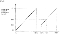
[Fig 2 ] montre que l'arrêt de la deuxième unité de séparation membranaire a lieu lorsque le débit requis est supérieur de 35% par rapport à la valeur seuil. Une fois la deuxième unité de séparation membranaire arrêtée, la première unité de séparation membranaire reçoit la totalité du flux de biogaz.
- lorsque le débit requis par l'exploitant augmente, le démarrage de la deuxième unité de séparation membranaire a lieu lorsque le débit requis est supérieur de 50% par rapport à la valeur seuil. La deuxième unité de séparation membranaire démarre alors avec une capacité de fonctionnement de 50%. Une fois la deuxième unité de séparation membranaire démarrée, sa capacité de fonctionnement correspondra toujours à l'écart en pourcentage par rapport à la valeur seuil ([
- Un fonctionnement des unités de séparation membranaire à un point de fonctionnement étudié par le fabricant pour que la consommation d'énergie et le rendement de conversion du méthane soient optimisé,
- Sous réserve que l'algorithme permette de changer les rôles de la première unité de séparation membranaire et de la seconde unité de séparation membranaire à la demande de l'exploitant, les périodes de maintenance préventive de chaque unité de séparation membranaire peuvent être optimisées.
However, this first way is not suitable for operations in which the flow rates of biogas to be treated or of the flow of biomethane (data D) required by the operator often oscillate between 100 and 200% of the threshold value. Indeed, this first way has several drawbacks:
- Membrane separation units, like any industrial installation, have an optimal range of energy consumption (ie a range of operating points for which the ratio of energy consumed per volume of biogas treated is minimum). Generally, the membrane separation unit is designed so that this optimum operating range is between the nominal speed of the installation and its maximum speed. If the biogas stream is evenly distributed between the membrane separation units, there is a wide range of biogas streams to be processed or biomethane stream (data D) required over which the membrane separation units are not within their range optimal energy consumption.
- Biogas purification units by membrane permeation also have an optimum range of methane conversion efficiency (ie a range of operating points for which the ratio of biomethane volume produced per volume of biogas treated is maximum). Generally, the unit is designed so that this optimum operating range is between the rated speed of the installation and its maximum speed. If the biogas stream is distributed evenly between the membrane separation units, there is a wide range of biogas streams to be processed or of the biomethane stream (data D) required over which the membrane separation units are not in a capacity operation allowing optimum methane conversion efficiency.
- Preventive and curative maintenance of equipment, and particularly of rotating machines, the maintenance of which is planned according to their hours of operation, is accelerated. Both units operate permanently, even in the event that a single unit in operation would treat the biogas produced, and it is therefore the components of the two units that wear out permanently.
- As long as the flow rate of the biogas flow to be treated or of the biomethane flow (data D) required by the operator is not greater than the threshold value, only the first membrane separation unit is in operation and receives the entire flow of biogas. The second membrane separation unit is shut down.
- When the flow rate of the flow of biogas to be treated or of the flow of biomethane (data D) required by the operator is greater than the threshold value, the first membrane separation unit A operates at maximum capacity.
- the algorithm can adjust the running capacity of parallel equipment by hysteresis. The hysteresis makes it possible to avoid the problems of untimely stops/starts of the membrane separation units. For example, the following values can be proposed as the basic setting of the hysteresis for the algorithm:
- when the flow rate required by the operator increases, the start-up of the second membrane separation unit takes place when the flow rate required is 50% higher than the threshold value. The second membrane separation unit then starts with an operating capacity of 50%. Once the second membrane separation unit is started, its operating capacity will always correspond to the percentage deviation from the threshold value ([
Fig 1 ]). - when the flow required by the operator drops:
[Fig 2 ] shows that the shutdown of the second membrane separation unit takes place when the required flow rate is 35% higher than the threshold value. Once the second membrane separation unit has stopped, the first membrane separation unit receives the entire flow of biogas.
- when the flow rate required by the operator increases, the start-up of the second membrane separation unit takes place when the flow rate required is 50% higher than the threshold value. The second membrane separation unit then starts with an operating capacity of 50%. Once the second membrane separation unit is started, its operating capacity will always correspond to the percentage deviation from the threshold value ([
- Operation of membrane separation units at an operating point studied by the manufacturer so that energy consumption and methane conversion efficiency are optimized,
- Provided that the algorithm makes it possible to change the roles of the first membrane separation unit and of the second membrane separation unit at the request of the operator, the preventive maintenance periods of each membrane separation unit can be optimized.
Claims (9)
Applications Claiming Priority (1)
| Application Number | Priority Date | Filing Date | Title |
|---|---|---|---|
| FR2010904A FR3115472B1 (en) | 2020-10-23 | 2020-10-23 | Device for adjusting the equipment of a biomethane production facility |
Publications (2)
| Publication Number | Publication Date |
|---|---|
| EP3988198A1 true EP3988198A1 (en) | 2022-04-27 |
| EP3988198B1 EP3988198B1 (en) | 2024-01-03 |
Family
ID=74871471
Family Applications (1)
| Application Number | Title | Priority Date | Filing Date |
|---|---|---|---|
| EP21202983.9A Active EP3988198B1 (en) | 2020-10-23 | 2021-10-15 | Device and process for adjusting the equipment of a facility for producing biomethane |
Country Status (2)
| Country | Link |
|---|---|
| EP (1) | EP3988198B1 (en) |
| FR (1) | FR3115472B1 (en) |
Cited By (2)
| Publication number | Priority date | Publication date | Assignee | Title |
|---|---|---|---|---|
| CN116414090A (en) * | 2023-03-10 | 2023-07-11 | 广东煜丰实业(集团)有限公司 | A method and device for controlling multi-line material cutting based on numerical control equipment |
| IT202300003402A1 (en) * | 2023-02-27 | 2024-08-27 | Synecom S R L | FLUORINATED GAS RECIRCULATION AND DEHUMIDIFICATION DEVICE |
Citations (3)
| Publication number | Priority date | Publication date | Assignee | Title |
|---|---|---|---|---|
| US20120000355A1 (en) * | 2010-06-30 | 2012-01-05 | Uop Llc | Flexible System To Remove Carbon Dioxide From A Feed Natural Gas |
| US20150336046A1 (en) * | 2012-11-14 | 2015-11-26 | Evonik Fibres Gmbh | Control of gas composition of a gas separation system having membranes |
| WO2020156902A1 (en) * | 2019-02-01 | 2020-08-06 | Evonik Fibres Gmbh | A device and a membrane process for separating gas components from a gas stream having varying composition or flow rate |
-
2020
- 2020-10-23 FR FR2010904A patent/FR3115472B1/en active Active
-
2021
- 2021-10-15 EP EP21202983.9A patent/EP3988198B1/en active Active
Patent Citations (3)
| Publication number | Priority date | Publication date | Assignee | Title |
|---|---|---|---|---|
| US20120000355A1 (en) * | 2010-06-30 | 2012-01-05 | Uop Llc | Flexible System To Remove Carbon Dioxide From A Feed Natural Gas |
| US20150336046A1 (en) * | 2012-11-14 | 2015-11-26 | Evonik Fibres Gmbh | Control of gas composition of a gas separation system having membranes |
| WO2020156902A1 (en) * | 2019-02-01 | 2020-08-06 | Evonik Fibres Gmbh | A device and a membrane process for separating gas components from a gas stream having varying composition or flow rate |
Cited By (3)
| Publication number | Priority date | Publication date | Assignee | Title |
|---|---|---|---|---|
| IT202300003402A1 (en) * | 2023-02-27 | 2024-08-27 | Synecom S R L | FLUORINATED GAS RECIRCULATION AND DEHUMIDIFICATION DEVICE |
| EP4420758A1 (en) * | 2023-02-27 | 2024-08-28 | Synecom S.r.l. | Device for recirculation and dehumidification of fluorinated gas |
| CN116414090A (en) * | 2023-03-10 | 2023-07-11 | 广东煜丰实业(集团)有限公司 | A method and device for controlling multi-line material cutting based on numerical control equipment |
Also Published As
| Publication number | Publication date |
|---|---|
| FR3115472B1 (en) | 2023-03-03 |
| EP3988198B1 (en) | 2024-01-03 |
| FR3115472A1 (en) | 2022-04-29 |
Similar Documents
| Publication | Publication Date | Title |
|---|---|---|
| EP3988198B1 (en) | Device and process for adjusting the equipment of a facility for producing biomethane | |
| EP4063000A1 (en) | Installation for the treatment by membrane permeation of a flow of biogas with a membrane separation unit with two modules | |
| FR3025117A1 (en) | PROCESS FOR PURIFYING BIOGAS BY MEMBRANE (S) AT NEGATIVE TEMPERATURE | |
| EP3369473A1 (en) | Facility and method for treatment of a feed gas stream comprising methane and carbon dioxide by membrane permeation | |
| FR3084840A1 (en) | TREATMENT BY MEMBRANE PERMEATION WITH ADJUSTMENT OF THE TEMPERATURE OF THE FIRST RETENTAT ACCORDING TO THE CONCENTRATION IN CH4 IN THE THIRD AND / OR FOURTH PERMEAT | |
| CN111321020A (en) | Apparatus and method for membrane permeation treatment gas flow for regulating third permeate suction pressure | |
| WO2023104815A1 (en) | Facility for producing liquid co2 and biomethane with a means for preventing the build-up od hydrogen and oxygen | |
| CN110813040B (en) | Membrane permeation treatment that adjusts the number of membranes used according to the pressure of the feed gas flow | |
| EP2545256B1 (en) | Electricity generation method using a gas/air separation unit and a combustion unit | |
| WO2021234073A1 (en) | Method for methanation of hydrogen h2 and carbon dioxide co2 or hydrogen h2 and carbon monoxide co for the production of methane ch4 | |
| Ojeda et al. | Improvement of methane content in a hydrogenotrophic anaerobic digester via the proper operation of membrane module integrated into an external-loop | |
| FR2740444A1 (en) | METHOD AND PLANT FOR PRODUCING HYDROGEN AND ENERGY | |
| EP3666367B1 (en) | System and method for treating a gaseous current by membrane permeation with adjustment of the suction pressure of the second permeate | |
| FR3120317A1 (en) | Installation for the production of biomethane and syngas from a flow of biogas with a means of adjusting the quality of the biogas | |
| EP4149654B1 (en) | Facility and method for producing biomethane with limited methane loss and limited co2 emissions | |
| EP3964558B1 (en) | Installation and method for adjusting the production of biomethane to the biomethane utilisation unit | |
| WO2021155986A1 (en) | Treatment of residual gases originating from biogas purification | |
| EP3610939A1 (en) | Treatment by membrane permeation with adjustment of the pressure of the feed gas stream according to the ch4 concentration in the second retentate | |
| EP3071676A1 (en) | Method for producing biomethane incorporating the production of heat for the methaniser using membrane separation | |
| EP3964280B1 (en) | Device for controlling a facility for treatment of biogas by membrane permeation | |
| Kumar et al. | Pre and post combustion capture of carbon dioxide via hydrate formation | |
| US20240328018A1 (en) | Method and apparatus for operating an electrolyser | |
| WO2023002006A1 (en) | Device and method for separating mixed dihydrogen in a natural gas network | |
| FR3121614A1 (en) | Treatment of biogas purification streams | |
| Tritopoulou et al. | White paper on Biogas Upgrading Economics–Comparison between biogas upgrading and electricity co-generation: Greece |
Legal Events
| Date | Code | Title | Description |
|---|---|---|---|
| PUAI | Public reference made under article 153(3) epc to a published international application that has entered the european phase |
Free format text: ORIGINAL CODE: 0009012 |
|
| STAA | Information on the status of an ep patent application or granted ep patent |
Free format text: STATUS: THE APPLICATION HAS BEEN PUBLISHED |
|
| AK | Designated contracting states |
Kind code of ref document: A1 Designated state(s): AL AT BE BG CH CY CZ DE DK EE ES FI FR GB GR HR HU IE IS IT LI LT LU LV MC MK MT NL NO PL PT RO RS SE SI SK SM TR |
|
| STAA | Information on the status of an ep patent application or granted ep patent |
Free format text: STATUS: REQUEST FOR EXAMINATION WAS MADE |
|
| 17P | Request for examination filed |
Effective date: 20221027 |
|
| RBV | Designated contracting states (corrected) |
Designated state(s): AL AT BE BG CH CY CZ DE DK EE ES FI FR GB GR HR HU IE IS IT LI LT LU LV MC MK MT NL NO PL PT RO RS SE SI SK SM TR |
|
| GRAP | Despatch of communication of intention to grant a patent |
Free format text: ORIGINAL CODE: EPIDOSNIGR1 |
|
| STAA | Information on the status of an ep patent application or granted ep patent |
Free format text: STATUS: GRANT OF PATENT IS INTENDED |
|
| INTG | Intention to grant announced |
Effective date: 20230313 |
|
| RIN1 | Information on inventor provided before grant (corrected) |
Inventor name: MANGEANT, BAPTISTE |
|
| GRAJ | Information related to disapproval of communication of intention to grant by the applicant or resumption of examination proceedings by the epo deleted |
Free format text: ORIGINAL CODE: EPIDOSDIGR1 |
|
| STAA | Information on the status of an ep patent application or granted ep patent |
Free format text: STATUS: REQUEST FOR EXAMINATION WAS MADE |
|
| GRAP | Despatch of communication of intention to grant a patent |
Free format text: ORIGINAL CODE: EPIDOSNIGR1 |
|
| STAA | Information on the status of an ep patent application or granted ep patent |
Free format text: STATUS: GRANT OF PATENT IS INTENDED |
|
| INTC | Intention to grant announced (deleted) | ||
| INTG | Intention to grant announced |
Effective date: 20230803 |
|
| GRAS | Grant fee paid |
Free format text: ORIGINAL CODE: EPIDOSNIGR3 |
|
| GRAA | (expected) grant |
Free format text: ORIGINAL CODE: 0009210 |
|
| STAA | Information on the status of an ep patent application or granted ep patent |
Free format text: STATUS: THE PATENT HAS BEEN GRANTED |
|
| AK | Designated contracting states |
Kind code of ref document: B1 Designated state(s): AL AT BE BG CH CY CZ DE DK EE ES FI FR GB GR HR HU IE IS IT LI LT LU LV MC MK MT NL NO PL PT RO RS SE SI SK SM TR |
|
| REG | Reference to a national code |
Ref country code: GB Ref legal event code: FG4D Free format text: NOT ENGLISH |
|
| REG | Reference to a national code |
Ref country code: DE Ref legal event code: R096 Ref document number: 602021008278 Country of ref document: DE |
|
| REG | Reference to a national code |
Ref country code: CH Ref legal event code: EP |
|
| REG | Reference to a national code |
Ref country code: IE Ref legal event code: FG4D Free format text: LANGUAGE OF EP DOCUMENT: FRENCH |
|
| REG | Reference to a national code |
Ref country code: LT Ref legal event code: MG9D |
|
| PG25 | Lapsed in a contracting state [announced via postgrant information from national office to epo] |
Ref country code: ES Free format text: LAPSE BECAUSE OF FAILURE TO SUBMIT A TRANSLATION OF THE DESCRIPTION OR TO PAY THE FEE WITHIN THE PRESCRIBED TIME-LIMIT Effective date: 20240103 |
|
| PG25 | Lapsed in a contracting state [announced via postgrant information from national office to epo] |
Ref country code: ES Free format text: LAPSE BECAUSE OF FAILURE TO SUBMIT A TRANSLATION OF THE DESCRIPTION OR TO PAY THE FEE WITHIN THE PRESCRIBED TIME-LIMIT Effective date: 20240103 |
|
| REG | Reference to a national code |
Ref country code: NL Ref legal event code: MP Effective date: 20240103 |
|
| REG | Reference to a national code |
Ref country code: AT Ref legal event code: MK05 Ref document number: 1646248 Country of ref document: AT Kind code of ref document: T Effective date: 20240103 |
|
| PG25 | Lapsed in a contracting state [announced via postgrant information from national office to epo] |
Ref country code: NL Free format text: LAPSE BECAUSE OF FAILURE TO SUBMIT A TRANSLATION OF THE DESCRIPTION OR TO PAY THE FEE WITHIN THE PRESCRIBED TIME-LIMIT Effective date: 20240103 |
|
| PG25 | Lapsed in a contracting state [announced via postgrant information from national office to epo] |
Ref country code: NL Free format text: LAPSE BECAUSE OF FAILURE TO SUBMIT A TRANSLATION OF THE DESCRIPTION OR TO PAY THE FEE WITHIN THE PRESCRIBED TIME-LIMIT Effective date: 20240103 |
|
| PG25 | Lapsed in a contracting state [announced via postgrant information from national office to epo] |
Ref country code: IS Free format text: LAPSE BECAUSE OF FAILURE TO SUBMIT A TRANSLATION OF THE DESCRIPTION OR TO PAY THE FEE WITHIN THE PRESCRIBED TIME-LIMIT Effective date: 20240503 |
|
| PG25 | Lapsed in a contracting state [announced via postgrant information from national office to epo] |
Ref country code: LT Free format text: LAPSE BECAUSE OF FAILURE TO SUBMIT A TRANSLATION OF THE DESCRIPTION OR TO PAY THE FEE WITHIN THE PRESCRIBED TIME-LIMIT Effective date: 20240103 |
|
| PG25 | Lapsed in a contracting state [announced via postgrant information from national office to epo] |
Ref country code: GR Free format text: LAPSE BECAUSE OF FAILURE TO SUBMIT A TRANSLATION OF THE DESCRIPTION OR TO PAY THE FEE WITHIN THE PRESCRIBED TIME-LIMIT Effective date: 20240404 |
|
| PG25 | Lapsed in a contracting state [announced via postgrant information from national office to epo] |
Ref country code: HR Free format text: LAPSE BECAUSE OF FAILURE TO SUBMIT A TRANSLATION OF THE DESCRIPTION OR TO PAY THE FEE WITHIN THE PRESCRIBED TIME-LIMIT Effective date: 20240103 Ref country code: RS Free format text: LAPSE BECAUSE OF FAILURE TO SUBMIT A TRANSLATION OF THE DESCRIPTION OR TO PAY THE FEE WITHIN THE PRESCRIBED TIME-LIMIT Effective date: 20240403 |
|
| PG25 | Lapsed in a contracting state [announced via postgrant information from national office to epo] |
Ref country code: CZ Free format text: LAPSE BECAUSE OF FAILURE TO SUBMIT A TRANSLATION OF THE DESCRIPTION OR TO PAY THE FEE WITHIN THE PRESCRIBED TIME-LIMIT Effective date: 20240103 Ref country code: AT Free format text: LAPSE BECAUSE OF FAILURE TO SUBMIT A TRANSLATION OF THE DESCRIPTION OR TO PAY THE FEE WITHIN THE PRESCRIBED TIME-LIMIT Effective date: 20240103 |
|
| PG25 | Lapsed in a contracting state [announced via postgrant information from national office to epo] |
Ref country code: RS Free format text: LAPSE BECAUSE OF FAILURE TO SUBMIT A TRANSLATION OF THE DESCRIPTION OR TO PAY THE FEE WITHIN THE PRESCRIBED TIME-LIMIT Effective date: 20240403 Ref country code: NO Free format text: LAPSE BECAUSE OF FAILURE TO SUBMIT A TRANSLATION OF THE DESCRIPTION OR TO PAY THE FEE WITHIN THE PRESCRIBED TIME-LIMIT Effective date: 20240403 Ref country code: LT Free format text: LAPSE BECAUSE OF FAILURE TO SUBMIT A TRANSLATION OF THE DESCRIPTION OR TO PAY THE FEE WITHIN THE PRESCRIBED TIME-LIMIT Effective date: 20240103 Ref country code: IS Free format text: LAPSE BECAUSE OF FAILURE TO SUBMIT A TRANSLATION OF THE DESCRIPTION OR TO PAY THE FEE WITHIN THE PRESCRIBED TIME-LIMIT Effective date: 20240503 Ref country code: HR Free format text: LAPSE BECAUSE OF FAILURE TO SUBMIT A TRANSLATION OF THE DESCRIPTION OR TO PAY THE FEE WITHIN THE PRESCRIBED TIME-LIMIT Effective date: 20240103 Ref country code: GR Free format text: LAPSE BECAUSE OF FAILURE TO SUBMIT A TRANSLATION OF THE DESCRIPTION OR TO PAY THE FEE WITHIN THE PRESCRIBED TIME-LIMIT Effective date: 20240404 Ref country code: CZ Free format text: LAPSE BECAUSE OF FAILURE TO SUBMIT A TRANSLATION OF THE DESCRIPTION OR TO PAY THE FEE WITHIN THE PRESCRIBED TIME-LIMIT Effective date: 20240103 Ref country code: BG Free format text: LAPSE BECAUSE OF FAILURE TO SUBMIT A TRANSLATION OF THE DESCRIPTION OR TO PAY THE FEE WITHIN THE PRESCRIBED TIME-LIMIT Effective date: 20240103 Ref country code: AT Free format text: LAPSE BECAUSE OF FAILURE TO SUBMIT A TRANSLATION OF THE DESCRIPTION OR TO PAY THE FEE WITHIN THE PRESCRIBED TIME-LIMIT Effective date: 20240103 |
|
| PG25 | Lapsed in a contracting state [announced via postgrant information from national office to epo] |
Ref country code: PL Free format text: LAPSE BECAUSE OF FAILURE TO SUBMIT A TRANSLATION OF THE DESCRIPTION OR TO PAY THE FEE WITHIN THE PRESCRIBED TIME-LIMIT Effective date: 20240103 Ref country code: PT Free format text: LAPSE BECAUSE OF FAILURE TO SUBMIT A TRANSLATION OF THE DESCRIPTION OR TO PAY THE FEE WITHIN THE PRESCRIBED TIME-LIMIT Effective date: 20240503 |
|
| PG25 | Lapsed in a contracting state [announced via postgrant information from national office to epo] |
Ref country code: SE Free format text: LAPSE BECAUSE OF FAILURE TO SUBMIT A TRANSLATION OF THE DESCRIPTION OR TO PAY THE FEE WITHIN THE PRESCRIBED TIME-LIMIT Effective date: 20240103 Ref country code: PT Free format text: LAPSE BECAUSE OF FAILURE TO SUBMIT A TRANSLATION OF THE DESCRIPTION OR TO PAY THE FEE WITHIN THE PRESCRIBED TIME-LIMIT Effective date: 20240503 Ref country code: PL Free format text: LAPSE BECAUSE OF FAILURE TO SUBMIT A TRANSLATION OF THE DESCRIPTION OR TO PAY THE FEE WITHIN THE PRESCRIBED TIME-LIMIT Effective date: 20240103 Ref country code: LV Free format text: LAPSE BECAUSE OF FAILURE TO SUBMIT A TRANSLATION OF THE DESCRIPTION OR TO PAY THE FEE WITHIN THE PRESCRIBED TIME-LIMIT Effective date: 20240103 |
|
| REG | Reference to a national code |
Ref country code: DE Ref legal event code: R097 Ref document number: 602021008278 Country of ref document: DE |
|
| PG25 | Lapsed in a contracting state [announced via postgrant information from national office to epo] |
Ref country code: DK Free format text: LAPSE BECAUSE OF FAILURE TO SUBMIT A TRANSLATION OF THE DESCRIPTION OR TO PAY THE FEE WITHIN THE PRESCRIBED TIME-LIMIT Effective date: 20240103 |
|
| PG25 | Lapsed in a contracting state [announced via postgrant information from national office to epo] |
Ref country code: SM Free format text: LAPSE BECAUSE OF FAILURE TO SUBMIT A TRANSLATION OF THE DESCRIPTION OR TO PAY THE FEE WITHIN THE PRESCRIBED TIME-LIMIT Effective date: 20240103 |
|
| PG25 | Lapsed in a contracting state [announced via postgrant information from national office to epo] |
Ref country code: EE Free format text: LAPSE BECAUSE OF FAILURE TO SUBMIT A TRANSLATION OF THE DESCRIPTION OR TO PAY THE FEE WITHIN THE PRESCRIBED TIME-LIMIT Effective date: 20240103 |
|
| PG25 | Lapsed in a contracting state [announced via postgrant information from national office to epo] |
Ref country code: SK Free format text: LAPSE BECAUSE OF FAILURE TO SUBMIT A TRANSLATION OF THE DESCRIPTION OR TO PAY THE FEE WITHIN THE PRESCRIBED TIME-LIMIT Effective date: 20240103 |
|
| PG25 | Lapsed in a contracting state [announced via postgrant information from national office to epo] |
Ref country code: SM Free format text: LAPSE BECAUSE OF FAILURE TO SUBMIT A TRANSLATION OF THE DESCRIPTION OR TO PAY THE FEE WITHIN THE PRESCRIBED TIME-LIMIT Effective date: 20240103 Ref country code: SK Free format text: LAPSE BECAUSE OF FAILURE TO SUBMIT A TRANSLATION OF THE DESCRIPTION OR TO PAY THE FEE WITHIN THE PRESCRIBED TIME-LIMIT Effective date: 20240103 Ref country code: RO Free format text: LAPSE BECAUSE OF FAILURE TO SUBMIT A TRANSLATION OF THE DESCRIPTION OR TO PAY THE FEE WITHIN THE PRESCRIBED TIME-LIMIT Effective date: 20240103 Ref country code: EE Free format text: LAPSE BECAUSE OF FAILURE TO SUBMIT A TRANSLATION OF THE DESCRIPTION OR TO PAY THE FEE WITHIN THE PRESCRIBED TIME-LIMIT Effective date: 20240103 Ref country code: DK Free format text: LAPSE BECAUSE OF FAILURE TO SUBMIT A TRANSLATION OF THE DESCRIPTION OR TO PAY THE FEE WITHIN THE PRESCRIBED TIME-LIMIT Effective date: 20240103 |
|
| PLBE | No opposition filed within time limit |
Free format text: ORIGINAL CODE: 0009261 |
|
| STAA | Information on the status of an ep patent application or granted ep patent |
Free format text: STATUS: NO OPPOSITION FILED WITHIN TIME LIMIT |
|
| 26N | No opposition filed |
Effective date: 20241007 |
|
| PG25 | Lapsed in a contracting state [announced via postgrant information from national office to epo] |
Ref country code: SI Free format text: LAPSE BECAUSE OF FAILURE TO SUBMIT A TRANSLATION OF THE DESCRIPTION OR TO PAY THE FEE WITHIN THE PRESCRIBED TIME-LIMIT Effective date: 20240103 |
|
| REG | Reference to a national code |
Ref country code: CH Ref legal event code: PL |
|
| PG25 | Lapsed in a contracting state [announced via postgrant information from national office to epo] |
Ref country code: MC Free format text: LAPSE BECAUSE OF FAILURE TO SUBMIT A TRANSLATION OF THE DESCRIPTION OR TO PAY THE FEE WITHIN THE PRESCRIBED TIME-LIMIT Effective date: 20240103 |
|
| PG25 | Lapsed in a contracting state [announced via postgrant information from national office to epo] |
Ref country code: LU Free format text: LAPSE BECAUSE OF NON-PAYMENT OF DUE FEES Effective date: 20241015 Ref country code: BE Free format text: LAPSE BECAUSE OF NON-PAYMENT OF DUE FEES Effective date: 20241031 |
|
| PG25 | Lapsed in a contracting state [announced via postgrant information from national office to epo] |
Ref country code: CH Free format text: LAPSE BECAUSE OF NON-PAYMENT OF DUE FEES Effective date: 20241031 |
|
| REG | Reference to a national code |
Ref country code: BE Ref legal event code: MM Effective date: 20241031 |
|
| PG25 | Lapsed in a contracting state [announced via postgrant information from national office to epo] |
Ref country code: FI Free format text: LAPSE BECAUSE OF FAILURE TO SUBMIT A TRANSLATION OF THE DESCRIPTION OR TO PAY THE FEE WITHIN THE PRESCRIBED TIME-LIMIT Effective date: 20240103 |
|
| PG25 | Lapsed in a contracting state [announced via postgrant information from national office to epo] |
Ref country code: IE Free format text: LAPSE BECAUSE OF NON-PAYMENT OF DUE FEES Effective date: 20241015 |
|
| PGFP | Annual fee paid to national office [announced via postgrant information from national office to epo] |
Ref country code: DE Payment date: 20251021 Year of fee payment: 5 |
|
| PGFP | Annual fee paid to national office [announced via postgrant information from national office to epo] |
Ref country code: GB Payment date: 20251022 Year of fee payment: 5 |
|
| PGFP | Annual fee paid to national office [announced via postgrant information from national office to epo] |
Ref country code: IT Payment date: 20251021 Year of fee payment: 5 |
|
| PGFP | Annual fee paid to national office [announced via postgrant information from national office to epo] |
Ref country code: FR Payment date: 20251030 Year of fee payment: 5 |
|
| PG25 | Lapsed in a contracting state [announced via postgrant information from national office to epo] |
Ref country code: CY Free format text: LAPSE BECAUSE OF FAILURE TO SUBMIT A TRANSLATION OF THE DESCRIPTION OR TO PAY THE FEE WITHIN THE PRESCRIBED TIME-LIMIT; INVALID AB INITIO Effective date: 20211015 |
|
| PG25 | Lapsed in a contracting state [announced via postgrant information from national office to epo] |
Ref country code: HU Free format text: LAPSE BECAUSE OF FAILURE TO SUBMIT A TRANSLATION OF THE DESCRIPTION OR TO PAY THE FEE WITHIN THE PRESCRIBED TIME-LIMIT; INVALID AB INITIO Effective date: 20211015 |