EP3988067A1 - Seating device - Google Patents
Seating device Download PDFInfo
- Publication number
- EP3988067A1 EP3988067A1 EP21203939.0A EP21203939A EP3988067A1 EP 3988067 A1 EP3988067 A1 EP 3988067A1 EP 21203939 A EP21203939 A EP 21203939A EP 3988067 A1 EP3988067 A1 EP 3988067A1
- Authority
- EP
- European Patent Office
- Prior art keywords
- support
- holder
- pressure surface
- seating
- seating device
- Prior art date
- Legal status (The legal status is an assumption and is not a legal conclusion. Google has not performed a legal analysis and makes no representation as to the accuracy of the status listed.)
- Pending
Links
Images


Classifications
-
- A—HUMAN NECESSITIES
- A61—MEDICAL OR VETERINARY SCIENCE; HYGIENE
- A61G—TRANSPORT, PERSONAL CONVEYANCES OR ACCOMMODATION SPECIALLY ADAPTED FOR PATIENTS OR DISABLED PERSONS; OPERATING TABLES OR CHAIRS; CHAIRS FOR DENTISTRY; FUNERAL DEVICES
- A61G5/00—Chairs or personal conveyances specially adapted for patients or disabled persons, e.g. wheelchairs
- A61G5/10—Parts, details or accessories
- A61G5/14—Standing-up or sitting-down aids
-
- A—HUMAN NECESSITIES
- A61—MEDICAL OR VETERINARY SCIENCE; HYGIENE
- A61G—TRANSPORT, PERSONAL CONVEYANCES OR ACCOMMODATION SPECIALLY ADAPTED FOR PATIENTS OR DISABLED PERSONS; OPERATING TABLES OR CHAIRS; CHAIRS FOR DENTISTRY; FUNERAL DEVICES
- A61G5/00—Chairs or personal conveyances specially adapted for patients or disabled persons, e.g. wheelchairs
- A61G5/10—Parts, details or accessories
- A61G5/12—Rests specially adapted therefor, e.g. for the head or the feet
- A61G5/128—Rests specially adapted therefor, e.g. for the head or the feet for feet
Definitions
- the invention relates to a seating device.
- the invention relates in particular to a seating device for individuals having difficulty sitting down and/or rising back up from the seated position.
- a motor is arranged in the chair for tilting the seat.
- Such chairs are rather heavy, which makes them difficult to move, and they are relatively expensive.
- the tilting mechanism is operated by manpower, using movable armrests, wherein due to exerting a downward force on the armrests, the seat is urged to tilt forward and thus enabled to support the individual longer when rising and enabled to give support sooner in case of sitting down.
- An effective embodiment thereof is described in European patent 2.808.001 .
- the invention provides a seating device for an individual, wherein the seating device comprises:
- the individual is able to allow the first support, the seat, to tilt by pressing down on the pressure surface of the second support with at least one foot, wherein the body weight can also be utilised. Arm power then no longer needs to play a role, other than ensuring stability during the movements the body makes.
- the seating device is provided with such an operating device on both sides of the holder.
- the first support is arranged on the holder so as to be rotatable about a lying centre line, wherein in particular the centre line has a fixed location in the holder.
- the operating device can then comprise an operating arm, which for the rotary motion about the centre line is fixedly connected to the first support. In that way, a kind of crankshaft arrangement is provided.
- the operating device comprises an operating assembly which functionally connects the operating arm to the second support and consequently to its pressure surface. In the first position of the first support, the operating arms is capable of extending downward and/or rearward from the centre line, so that it remains below the seat, which is advantageous to the occupation of space and to safety.
- the pressure surface of the second support is arranged on the holder so as to be at least partially linearly movable, in particular movable up and down, so that the individual is able to move the pressure surface of the second support easily from its first position into its second position by letting the feet exert pressure on it.
- the pressure surface can be linearly moved in its entirety. In the first and second positions, the orientation of the pressure surface can then be the same, in particular horizontal. In an alternative embodiment, the pressure surface can be moved so as to swing or rotate. A combination of both movements is possible.
- the direction of rotation of the pressure surface in the movement from its first into its second position can be opposite to that of the first support from the seating position into the transitional position.
- the second support can be moved from the first position into a second position that abuts the basis flat, in which the basis is contacted in a force-transferring manner. In that way, the second support can be positioned in a stable position that is safe for the individual, at the start of the process of sitting down and/or at the end of the process of standing up.
- the operating assembly comprises an elongated element transferring tensile force.
- an element such as a rod or a cable
- requires little space as a result of which its inclusion in the operating device in a chair can be simple.
- the advantage of a cable, (toothed) belt, cord, chain and the like is flexibility, as a result of which inclusion in a housing can be simple.
- one end of the elongated element can be attached to the outer end of the operating arm and the other end can be attached, directly or indirectly, but near, to the second support.
- the second support provides a pressure surface to at least two feet, thus improving the balance of the individual during the movements, as well as the forces the individual may exert on the second support.
- the second support provides a pressure surface for at least three feet. A caregiver will then be able to increase the pressure on the second support using a foot, should this be necessary.
- the second support may comprise two pressure surfaces leaving a passage open in between them, which passage preferably has a width of at least the horizontal spatial occupation of two legs. In that way, an individual having no difficulties sitting down is able to sit down the regular way without using the second support when doing so. However, it is available for use when standing up.
- the second support can be folded up for that purpose.
- the pressure surface of the second support has a width corresponding to the width of the first support. The individual then has a lot of freedom in choosing the support position for his feet, and there is room as well for the foot of a caregiver, should assistance be required. Also in that case the second support can be folded up.
- the holder can comprise a guide for the second support when its pressure surface is moved between the first and second positions.
- the holder comprises a support leg for supporting the holder on a basis, wherein the support leg forms the guide. It can also have a double configuration, having a support leg forming such a guide on each side of the seating device.
- the second support can be attached to a guide member that is guided by the guide.
- the guide may be substantially vertically oriented for an up-and-down motion of the guide member.
- the pressure surface of the second support can be movably attached to the guide member, wherein the pressure surface of the second support is movable between a level position and a forwardly and downwardly tilted position.
- the second support In that position, which may correspond to the first position of the pressure surface of the second support, the second support is able to contact the basis, or nearly so. A front edge of the second support then remains near the basis, both in the first position and in the second position. In the first position, the second support will not pose an injury hazard to others and the likelihood of an individual getting their trouser-leg caught on the second support is reduced.
- the holder can be configured in various ways.
- the holder can for instance be fixedly attached to a wall or on a basis.
- the holder can also be mobile.
- the holder may have at least two support legs, for instance two support legs at the front and two support wheels at the rear, or four support legs, one at each corner.
- the seating device can also be designed like a (walker-) wheelchair, wherein the holder forms a frame and is provided with four wheels.
- a seating device can be suitable for use in combination with a toilet bowl, as a so-called commode chair that may or may not be mobile, also called an over the commode seat.
- the holder may define a space between the support legs/support wheels for accommodating a toilet bowl.
- the first support can have a passage for toilet use of the individual sitting on it.
- the seating device is permanently placed at a toilet bowl, for instance attached to the rear wall or attached to the basis.
- the second support can be suspended at the front of the holder from a downwardly extending suspension. This suspension then forms the guide and ends at a level situated higher than the bottom of the wheels.
- pre-biassing means such as springs
- pre-biassing means can be provided in the seating device according to the invention, for urging the seat into the seating position in the condition in which it is not occupied by an individual.
- such means can be provided for biassing the seat into the transitional position.
- the seating device according to the invention can be provided with a backrest.
- the chair 1 shown in figures 1A , B and C has a holder in the shape of a frame 2 with two front legs 4a and two rear legs 4b, with which the chair 1 is able to stand on the basis 100.
- the chair 1 further comprises a seat or first support 3 supported on the frame 2 and two armrests 5.
- the chair 1 comprises a foot plate or second support 6 extending along the width of the chair, which foot plate or second support is connected to the front legs 4a and defines a pressure surface 6a for the feet.
- the seat 3 is movable, rotatable, about horizontal centre line S between the seating position of figure 1A and the transitional position of figure 1B .
- an operating device 20 is arranged on the frame 2 on both sides. This operating device forms a connection between the foot plate 6 and the seat 3.
- the operating device 20 comprises a guide sleeve 7 for the foot plate 6, which guide sleeve is guided on a front leg 4a so as to be movable up and down.
- the operating device 20 furthermore comprises a cable 8, one end of which is attached to the guide sleeve 7 and the other end of which is attached to an operating arm 10 to be further discussed below.
- the cable 8 runs between both outer ends about a cable pulley 11 and about a cable pulley 9, which cable pulleys are idle.
- the seat 3 is attached so as to be rotationally fixed to a stationary shaft 14 that is bearing mounted in the frame 2, the shaft and the operating arm 10 forming one rotatable unit.
- the cable pulley 11 is placed on the shaft 14 so as to be concentric and idle.
- the foot plate 6 has a front edge 15 and at the rear is attached by means of a hinge 13 to the bottom end of the guide sleeve 7 so as to be rotatable in the vertical plane.
- the operating arm 10 and the cable pulleys 9 and 11 are housed in a side casing 12, and shielded off by it.
- the cable 8 runs through the interior of the front leg 4a.
- the chair 1 can also be of use when sitting down.
- the individual will then stand with their back facing the chair 1, and place both feet on the pressure surface 6a of the foot plate 6, which is then moved into abutment with the basis (starting from the situation of figure 1A ).
- the seat 3 will rotate into the transitional position of figure 1B .
- the individual then places their buttocks against the seat 3 and allows their body to lower backwards. While doing so, the individual can allow the pressure of the feet to become less. Due to the initial pressure on the foot plate 6, the seat 3 is able to provide a counterforce against the sitting down motion, as a result of which the individual is able to sit down in a more controlled manner. Naturally, this depends on the condition of the individual.
- the wide foot plate 6 provides the possibility to do so: the other person can influence the force on the pressure surface 6a of the foot plate 6 with their own foot.
- the chair 1 is placed over a toilet bowl 200.
- the seat 3' is configured here with a passage (not shown here), comparable with a toilet seat. In this case, the seat 3' is positioned slightly over the toilet seat 201 of the toilet bowl 200.
- the use of the chair 1 is in accordance with what has been discussed above. After using the toilet and once the individual has removed themselves from the chair, the chair can be used elsewhere.
- the exemplary embodiment of figures 3A and 3B substantially corresponds to the one of the previous figures.
- the chair 1' now is a walker-wheelchair.
- the foot plate 6 has been replaced here by two footrests 6' that can be folded up.
- the footrests 6' form pressure surfaces 6a' and at the location of hinge 13 are attached to a guide sleeve 7 so as to be folded up, which guide sleeve is guided so as to slide up and down a suspension rod 24 forming one unity with the frame.
- the two footrests 6' leave a passage free in between them, either after folding up or not, so that the individual is able to sit down without contacting them, or can be assisted in sitting down by a caregiver.
- the foot plates 6' can provide a support to the feet of the individual sitting on the seat.
- the embodiment of the operating device 20' is furthermore in accordance with the operating device 20 of chair 1.
- a stop that is not shown ensures that the guide sleeve 7 cannot slide from the front leg 4a or the suspension rod 24.
- the wheels 4a will for that matter be rotated 180 degrees relative to the depiction, so that they do not conflict with the guide sleeve 7'.
Landscapes
- Health & Medical Sciences (AREA)
- Life Sciences & Earth Sciences (AREA)
- Animal Behavior & Ethology (AREA)
- General Health & Medical Sciences (AREA)
- Public Health (AREA)
- Veterinary Medicine (AREA)
- Chair Legs, Seat Parts, And Backrests (AREA)
- Special Chairs (AREA)
Abstract
- a holder;
- a first support arranged on the holder, the first support having a support surface for supporting the buttocks of an individual;
- a second support arranged on the holder, the second support having a pressure surface or support surface for a foot of the individual;
- wherein the first support is movable relative to the holder between a seating position for the individual and a forwardly tilted transitional position for the individual wherein the first support surface has a predominantly higher level than it has in the seating position,
- wherein the pressure surface is movable relative to the holder between a first position and a second position, wherein the pressure surface in the first position is situated at a predominantly higher level than it is in the second position,
wherein the second support is part of an operating device for moving the first support between the seating position and the transitional position, wherein the operating device is configured for moving the first support from its seating position into its transitional position, during a movement of the pressure surface from its first position into its second position.
Description
- The invention relates to a seating device. The invention relates in particular to a seating device for individuals having difficulty sitting down and/or rising back up from the seated position.
- Chairs having a seat that can be tilted forward are known in many embodiments.
- In a number of embodiments a motor is arranged in the chair for tilting the seat. Such chairs are rather heavy, which makes them difficult to move, and they are relatively expensive.
- In a number of other, more lightweight and cheaper embodiments, the tilting mechanism is operated by manpower, using movable armrests, wherein due to exerting a downward force on the armrests, the seat is urged to tilt forward and thus enabled to support the individual longer when rising and enabled to give support sooner in case of sitting down. An effective embodiment thereof is described in
European patent 2.808.001 . - It is possible that the individual is handicapped to such an extent that he or she is incapable of properly operating the armrests. In such cases that individual will have to call in assistance or make use of a motor-driven seat.
- It is an object of the invention to provide a seating device that also facilitates rising and/or sitting down for individuals who have little (muscle) power in their arms.
- It is an object of the invention to provide a seating device with an operating device for tilting the seat that takes up little space in the seating device.
- It is an object of the invention to provide a seating device that is suitable as auxiliary seating device for visiting the toilet.
- To that end, according to one aspect, the invention provides a seating device for an individual, wherein the seating device comprises:
- a holder;
- a first support arranged on the holder, the first support having a support surface for supporting the buttocks of an individual;
- a second support arranged on the holder, the second support having a pressure surface or support surface for a foot of the individual;
- wherein the first support is movable relative to the holder between a seating position for the individual and a forwardly tilted transitional position for the individual wherein the first support surface has a predominantly higher level than it has in the seating position,
- wherein the pressure surface of the second support is movable relative to the holder between a first position and a second position, wherein the pressure surface in the first position is situated at a predominantly, in particular at least almost entirely, higher level than it is in the second position,
- That way, the individual is able to allow the first support, the seat, to tilt by pressing down on the pressure surface of the second support with at least one foot, wherein the body weight can also be utilised. Arm power then no longer needs to play a role, other than ensuring stability during the movements the body makes. In one embodiment, the seating device is provided with such an operating device on both sides of the holder.
- In one embodiment, the first support is arranged on the holder so as to be rotatable about a lying centre line, wherein in particular the centre line has a fixed location in the holder. The operating device can then comprise an operating arm, which for the rotary motion about the centre line is fixedly connected to the first support. In that way, a kind of crankshaft arrangement is provided. In addition, the operating device comprises an operating assembly which functionally connects the operating arm to the second support and consequently to its pressure surface. In the first position of the first support, the operating arms is capable of extending downward and/or rearward from the centre line, so that it remains below the seat, which is advantageous to the occupation of space and to safety.
- In one embodiment, the pressure surface of the second support is arranged on the holder so as to be at least partially linearly movable, in particular movable up and down, so that the individual is able to move the pressure surface of the second support easily from its first position into its second position by letting the feet exert pressure on it. The pressure surface can be linearly moved in its entirety. In the first and second positions, the orientation of the pressure surface can then be the same, in particular horizontal. In an alternative embodiment, the pressure surface can be moved so as to swing or rotate. A combination of both movements is possible.
- The direction of rotation of the pressure surface in the movement from its first into its second position can be opposite to that of the first support from the seating position into the transitional position.
- In one embodiment, the second support can be moved from the first position into a second position that abuts the basis flat, in which the basis is contacted in a force-transferring manner. In that way, the second support can be positioned in a stable position that is safe for the individual, at the start of the process of sitting down and/or at the end of the process of standing up.
- In a simple embodiment, the operating assembly comprises an elongated element transferring tensile force. Such an element, such as a rod or a cable, requires little space as a result of which its inclusion in the operating device in a chair can be simple. The advantage of a cable, (toothed) belt, cord, chain and the like is flexibility, as a result of which inclusion in a housing can be simple. In the above-mentioned case of an operating arm, one end of the elongated element can be attached to the outer end of the operating arm and the other end can be attached, directly or indirectly, but near, to the second support.
- In one embodiment, the second support provides a pressure surface to at least two feet, thus improving the balance of the individual during the movements, as well as the forces the individual may exert on the second support.
- In a special embodiment, the second support provides a pressure surface for at least three feet. A caregiver will then be able to increase the pressure on the second support using a foot, should this be necessary.
- The second support may comprise two pressure surfaces leaving a passage open in between them, which passage preferably has a width of at least the horizontal spatial occupation of two legs. In that way, an individual having no difficulties sitting down is able to sit down the regular way without using the second support when doing so. However, it is available for use when standing up. Optionally, the second support can be folded up for that purpose.
- In another embodiment, the pressure surface of the second support has a width corresponding to the width of the first support. The individual then has a lot of freedom in choosing the support position for his feet, and there is room as well for the foot of a caregiver, should assistance be required. Also in that case the second support can be folded up.
- At the front, the holder can comprise a guide for the second support when its pressure surface is moved between the first and second positions. In one embodiment thereof, the holder comprises a support leg for supporting the holder on a basis, wherein the support leg forms the guide. It can also have a double configuration, having a support leg forming such a guide on each side of the seating device. The second support can be attached to a guide member that is guided by the guide. The guide may be substantially vertically oriented for an up-and-down motion of the guide member. The pressure surface of the second support can be movably attached to the guide member, wherein the pressure surface of the second support is movable between a level position and a forwardly and downwardly tilted position. In that position, which may correspond to the first position of the pressure surface of the second support, the second support is able to contact the basis, or nearly so. A front edge of the second support then remains near the basis, both in the first position and in the second position. In the first position, the second support will not pose an injury hazard to others and the likelihood of an individual getting their trouser-leg caught on the second support is reduced.
- The holder can be configured in various ways. The holder can for instance be fixedly attached to a wall or on a basis. The holder can also be mobile. The holder may have at least two support legs, for instance two support legs at the front and two support wheels at the rear, or four support legs, one at each corner. The seating device can also be designed like a (walker-) wheelchair, wherein the holder forms a frame and is provided with four wheels.
- A seating device according to the invention can be suitable for use in combination with a toilet bowl, as a so-called commode chair that may or may not be mobile, also called an over the commode seat. In that case the holder may define a space between the support legs/support wheels for accommodating a toilet bowl. For that purpose, the first support can have a passage for toilet use of the individual sitting on it. Alternatively the seating device is permanently placed at a toilet bowl, for instance attached to the rear wall or attached to the basis.
- In case the holder is provided with wheels, it needs to be prevented that the second support and the front wheels conflict with each other. As is usual for (foldable and removable) footrests in wheelchairs, the second support can be suspended at the front of the holder from a downwardly extending suspension. This suspension then forms the guide and ends at a level situated higher than the bottom of the wheels.
- Optionally, pre-biassing means, such as springs, can be provided in the seating device according to the invention, for urging the seat into the seating position in the condition in which it is not occupied by an individual. Alternatively, such means can be provided for biassing the seat into the transitional position.
- The seating device according to the invention can be provided with a backrest.
- The aspects and measures described in this description and the claims of the application and/or shown in the drawings of this application may where possible also be used individually. Said individual aspects and other aspects may be the subject of divisional patent applications relating thereto. This particularly applies to the measures and aspects that are described per se in the sub claims.
- The invention will be elucidated on the basis of a number of exemplary embodiments shown in the attached drawings, in which:
-
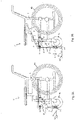
Figures 1A and 1B show side views of a first exemplary embodiment of a seating device according to the invention, with the seat in the seating position and the seat in the upwardly tilted transitional position, respectively; -
Figure 1C shows the seating device offigure 1A in front view according to arrow IC; -
Figure 2 shows the seating device offigures 1A-C placed over a toilet bowl; and -
Figures 3A and 3B show side views of a second exemplary embodiment of a seating device according to the invention, with the seat in the seating position and the seat in the upwardly tilted transitional position, respectively. - The
chair 1 shown infigures 1A , B and C has a holder in the shape of aframe 2 with twofront legs 4a and tworear legs 4b, with which thechair 1 is able to stand on thebasis 100. Thechair 1 further comprises a seat orfirst support 3 supported on theframe 2 and twoarmrests 5. In addition, thechair 1 comprises a foot plate orsecond support 6 extending along the width of the chair, which foot plate or second support is connected to thefront legs 4a and defines apressure surface 6a for the feet. - At the front, the
seat 3 is movable, rotatable, about horizontal centre line S between the seating position offigure 1A and the transitional position offigure 1B . For the movement of the seat from the seating position into the transitional position an operatingdevice 20 is arranged on theframe 2 on both sides. This operating device forms a connection between thefoot plate 6 and theseat 3. - The operating
device 20 comprises aguide sleeve 7 for thefoot plate 6, which guide sleeve is guided on afront leg 4a so as to be movable up and down. The operatingdevice 20 furthermore comprises acable 8, one end of which is attached to theguide sleeve 7 and the other end of which is attached to anoperating arm 10 to be further discussed below. Thecable 8 runs between both outer ends about acable pulley 11 and about acable pulley 9, which cable pulleys are idle. - The
seat 3 is attached so as to be rotationally fixed to astationary shaft 14 that is bearing mounted in theframe 2, the shaft and theoperating arm 10 forming one rotatable unit. Thecable pulley 11 is placed on theshaft 14 so as to be concentric and idle. - The
foot plate 6 has afront edge 15 and at the rear is attached by means of ahinge 13 to the bottom end of theguide sleeve 7 so as to be rotatable in the vertical plane. - The
operating arm 10 and the cable pulleys 9 and 11 are housed in aside casing 12, and shielded off by it. Thecable 8 runs through the interior of thefront leg 4a. - When in use, an individual sits on the
seat 3. Due to the position of the operating arm 10 (figure 1A ) an upward tensile force is exerted on theguide sleeve 7 via thecable 8 in thefront leg 4a, which keeps the guide sleeve in a first position, as a result of which thefoot plate 6 is kept at a distance above thebasis 100 with its rear end. Due to thehinge 13, thefoot plate 6 is allowed to tilt forward and downward, so that thefront edge 15 gets closer to or ends up on thebasis 100. - When the individual wishes to rise, he or she moves their body by tilting the torso forward, so that the feet start exerting a weight force F onto the
pressure surface 6a and the foot plate 6 (figure 1B ). As a result thefoot plate 6 will be urged down, direction A, and consequently theguide sleeve 7 will move downwards along thefront leg 4a. Consequently, thecable 8 will be pulled at in direction B, which via the cable pulleys 11 and 9 results in a tensile force C onto the outer end of theoperating arm 10. As a result, this arm will rotate about the centre line S in the direction D, and due to the rotation-fixed connection of thearm 10 to theseat 3, theseat 3 will rotate upwards with its rear end, direction E. - This process continues until the
foot plate 6 abuts thebasis 100 flat, as shown infigure 1B , and theseat 3 is in the transitional position. The individual can then continue the rising motion, thus far assisted by the forced motion of theseat 3. Once the individual is free from thechair 1, including thefoot plate 6, the seat rotates back to the position offigure 1A , due to its mass. It is also possible to effect this by means of springs that are active on the seat and/or the guide sleeve. - The
chair 1 can also be of use when sitting down. The individual will then stand with their back facing thechair 1, and place both feet on thepressure surface 6a of thefoot plate 6, which is then moved into abutment with the basis (starting from the situation offigure 1A ). As a result, theseat 3 will rotate into the transitional position offigure 1B . The individual then places their buttocks against theseat 3 and allows their body to lower backwards. While doing so, the individual can allow the pressure of the feet to become less. Due to the initial pressure on thefoot plate 6, theseat 3 is able to provide a counterforce against the sitting down motion, as a result of which the individual is able to sit down in a more controlled manner. Naturally, this depends on the condition of the individual. - If assistance of another person, such as a caregiver, is required, the
wide foot plate 6 provides the possibility to do so: the other person can influence the force on thepressure surface 6a of thefoot plate 6 with their own foot. - In
figure 2 , thechair 1 is placed over atoilet bowl 200. The seat 3' is configured here with a passage (not shown here), comparable with a toilet seat. In this case, the seat 3' is positioned slightly over thetoilet seat 201 of thetoilet bowl 200. The use of thechair 1 is in accordance with what has been discussed above. After using the toilet and once the individual has removed themselves from the chair, the chair can be used elsewhere. - The exemplary embodiment of
figures 3A and 3B substantially corresponds to the one of the previous figures. However, the chair 1' now is a walker-wheelchair. Thefoot plate 6 has been replaced here by two footrests 6' that can be folded up. The footrests 6' form pressure surfaces 6a' and at the location ofhinge 13 are attached to aguide sleeve 7 so as to be folded up, which guide sleeve is guided so as to slide up and down asuspension rod 24 forming one unity with the frame. The two footrests 6' leave a passage free in between them, either after folding up or not, so that the individual is able to sit down without contacting them, or can be assisted in sitting down by a caregiver. In the position offigure 3A , the foot plates 6' can provide a support to the feet of the individual sitting on the seat. - The embodiment of the operating device 20' is furthermore in accordance with the operating
device 20 ofchair 1. - A stop that is not shown ensures that the
guide sleeve 7 cannot slide from thefront leg 4a or thesuspension rod 24. Thewheels 4a will for that matter be rotated 180 degrees relative to the depiction, so that they do not conflict with the guide sleeve 7'. - The invention is/inventions are not at all limited to the embodiments discussed in the description and shown in the drawings. The above description has been included to illustrate the operation of preferred embodiments of the invention and not to limit the scope of the invention. Starting from the above explanation, many variations that fall within the spirit and scope of the present invention will be evident to an expert. Variations of the parts described in the description and shown in the drawings are possible. They can be used individually in other embodiments of the invention(s). Parts of the various examples given can be combined together.
Claims (15)
- Seating device for an individual, wherein the seating device comprises:- a holder;- a first support arranged on the holder, the first support having a support surface for supporting the buttocks of an individual;- a second support arranged on the holder, the second support having a pressure surface or support surface for a foot of the individual;- wherein the first support is movable relative to the holder between a seating position for the individual and a forwardly tilted transitional position for the individual wherein the first support surface has a predominantly higher level than it has in the seating position,- wherein the pressure surface of the second support is movable relative to the holder between a first position and a second position, wherein the pressure surface in the first position is situated at a predominantly higher level than it is in the second position,wherein the second support is part of an operating device for moving the first support between the seating position and the transitional position, wherein the operating device is configured for moving the first support from its seating position into its transitional position, during a movement of the pressure surface from its first position into its second position.
- Seating device according to claim 1,
wherein the first support is arranged on the holder so as to be rotatable about a lying centre line, wherein, in particular, the centre line has a fixed location in the holder, wherein, preferably, the operating device comprises an operating arm, which for the rotary motion about the centre line is fixedly connected to the first support and wherein the operating device comprises an operating assembly which functionally connects the operating arm to the second support and consequently to its pressure surface. - Seating device according to claim 1 or 2,
wherein the pressure surface of the second support is arranged on the holder so as to be at least partially linearly movable, in particular movable up and down, in the movement between its first position and its second position. - Seating device according to any one of the preceding claims, wherein the pressure surface of the second support is arranged on the holder so as to be movable in an at least partially swingable or rotatable manner, in particular movable up and down in a swingable or rotatable manner, in the movement between its first position and its second position, wherein, preferably, the direction of rotation of the pressure surface in the movement from its first into its second position can be opposite to that of the first support from the seating position into the transitional position.
- Seating device according to any one of the preceding claims, wherein the pressure surface of the second support can be moved from the first position into a second position that abuts the basis flat, in which the basis is contacted in a force-transferring manner.
- Seating device according to any one of the preceding claims, wherein the operating device comprises an elongated element transferring tensile force, wherein, preferably, the elongated element is flexible and is a cable, (toothed) belt, cord, chain or something similar.
- Seating device according to claim 2 and according to claim 6, wherein the operating device comprises an operating arm, which is fixedly connected to the first support for the rotary motion about the centre line and wherein the operating device comprises an operating assembly functionally connecting the operating arm to the second support and consequently to its pressure surface, wherein the elongated element is attached to the outer end of the operating arm.
- Seating device according to any one of the preceding claims, wherein the second support provides a pressure surface to at least two feet, preferably to at least three feet, and/or,
wherein, preferably,- the second support comprises two pressure surfaces leaving a passage open in between them, which passage preferably has a width of at least the horizontal spatial occupation of two legs,- or the pressure surface has a width corresponding to the width of the first support. - Seating device according to any one of the preceding claims, wherein the holder comprises a guide at the front for guiding, in particular substantially vertical guiding, of the second support during the movement of the pressure surface between the first and second positions, wherein, preferably, the second support is attached to a guide member that is guided by the guide.
- Seating device according to claim 9, wherein the holder comprises a support leg for support on a basis, wherein the support leg forms the guide, wherein, preferably, the pressure surface of the second support is movably attached to a guide member that is guided by the guide, wherein the pressure surface of the second support is movable between a level position and a forwardly and downwardly tilted position.
- Seating device according to any one of the preceding claims, wherein the holder has at least two support legs, preferably four support legs, wherein, preferably, the holder defines a space between the support legs for the accommodation of a toilet bowl.
- Seating device according to any one of the preceding claims, wherein the holder is provided with four wheels.
- Seating device according to claims 9 and 12, wherein, at the front, the holder comprises a downwardly extending suspension for the second support, which forms the guide, and ends at a level situated higher than the bottom of the wheels.
- Seating device according to any one of the preceding claims, wherein the first support has a passage for toilet use of the individual sitting on it.
- Seating device according to any one of the preceding claims, provided with a said operating device on both sides of the holder.
Applications Claiming Priority (1)
| Application Number | Priority Date | Filing Date | Title |
|---|---|---|---|
| NL2026723A NL2026723B1 (en) | 2020-10-21 | 2020-10-21 | seating arrangement |
Publications (1)
| Publication Number | Publication Date |
|---|---|
| EP3988067A1 true EP3988067A1 (en) | 2022-04-27 |
Family
ID=74557224
Family Applications (1)
| Application Number | Title | Priority Date | Filing Date |
|---|---|---|---|
| EP21203939.0A Pending EP3988067A1 (en) | 2020-10-21 | 2021-10-21 | Seating device |
Country Status (2)
| Country | Link |
|---|---|
| EP (1) | EP3988067A1 (en) |
| NL (1) | NL2026723B1 (en) |
Citations (11)
| Publication number | Priority date | Publication date | Assignee | Title |
|---|---|---|---|---|
| GB1350835A (en) * | 1971-06-23 | 1974-04-24 | Bressler P W | Wheelchair |
| US4120530A (en) * | 1976-04-30 | 1978-10-17 | Michael Imbro | Invalid chairs |
| US4623194A (en) * | 1983-05-10 | 1986-11-18 | International Diffusion Consommateur | Body-supporting device for wheelchair for handicapped person comprising a structure allowing an upright position |
| DE29721734U1 (en) * | 1997-12-09 | 1998-02-05 | Chang, Chen I, Taiping, Tauchung | Building a walking aid |
| US5984338A (en) * | 1996-06-27 | 1999-11-16 | Levo Ag Dottikon | Lightweight stabilized raising chair |
| US20090072513A1 (en) * | 2007-09-18 | 2009-03-19 | Heinrich Perk | Upright wheelchair |
| EP2374438A1 (en) * | 2010-04-07 | 2011-10-12 | Lloyd Linden Inc. | Wheelchair apparatus with assistant function |
| US8113587B1 (en) * | 2010-01-13 | 2012-02-14 | Majid Zarinfar | Portable lift chair |
| EP2808001A1 (en) | 2012-11-23 | 2014-12-03 | Anthonius Johannes Tolboom | Seating device with rising aid |
| US20150272798A1 (en) * | 2014-03-31 | 2015-10-01 | Kuan-Fu Hsieh | Rise assisting structure |
| US20170246061A1 (en) * | 2016-02-25 | 2017-08-31 | Judie McClean | Wheelchair Lift Assembly |
-
2020
- 2020-10-21 NL NL2026723A patent/NL2026723B1/en active
-
2021
- 2021-10-21 EP EP21203939.0A patent/EP3988067A1/en active Pending
Patent Citations (11)
| Publication number | Priority date | Publication date | Assignee | Title |
|---|---|---|---|---|
| GB1350835A (en) * | 1971-06-23 | 1974-04-24 | Bressler P W | Wheelchair |
| US4120530A (en) * | 1976-04-30 | 1978-10-17 | Michael Imbro | Invalid chairs |
| US4623194A (en) * | 1983-05-10 | 1986-11-18 | International Diffusion Consommateur | Body-supporting device for wheelchair for handicapped person comprising a structure allowing an upright position |
| US5984338A (en) * | 1996-06-27 | 1999-11-16 | Levo Ag Dottikon | Lightweight stabilized raising chair |
| DE29721734U1 (en) * | 1997-12-09 | 1998-02-05 | Chang, Chen I, Taiping, Tauchung | Building a walking aid |
| US20090072513A1 (en) * | 2007-09-18 | 2009-03-19 | Heinrich Perk | Upright wheelchair |
| US8113587B1 (en) * | 2010-01-13 | 2012-02-14 | Majid Zarinfar | Portable lift chair |
| EP2374438A1 (en) * | 2010-04-07 | 2011-10-12 | Lloyd Linden Inc. | Wheelchair apparatus with assistant function |
| EP2808001A1 (en) | 2012-11-23 | 2014-12-03 | Anthonius Johannes Tolboom | Seating device with rising aid |
| US20150272798A1 (en) * | 2014-03-31 | 2015-10-01 | Kuan-Fu Hsieh | Rise assisting structure |
| US20170246061A1 (en) * | 2016-02-25 | 2017-08-31 | Judie McClean | Wheelchair Lift Assembly |
Also Published As
| Publication number | Publication date |
|---|---|
| NL2026723B1 (en) | 2022-06-28 |
Similar Documents
| Publication | Publication Date | Title |
|---|---|---|
| US4453766A (en) | Lift chair for disabled person | |
| JP4510762B2 (en) | Sheet folding mechanism | |
| CN110461294B (en) | wheelchair for walking | |
| US3672722A (en) | Invalid chair having adjustable headrest seat and footrest | |
| CN112739428A (en) | Buttock pressure training machine | |
| JP3032746B2 (en) | wheelchair | |
| JP2000300611A (en) | Standing assistance chair | |
| JP2009006023A (en) | Chair for medical use | |
| JP2003079668A (en) | Standing assistance chair | |
| KR102306638B1 (en) | Standing-assisted chair | |
| JP3660863B2 (en) | Rise support device | |
| JP2003235902A (en) | Standing assistance chair | |
| JP3718628B2 (en) | Chair | |
| JP2005137639A (en) | Standing support chair | |
| JP2001129033A (en) | Nursing assistance device | |
| JP2003052754A (en) | Body-raising device for a wheelchair or chair, and a wheelchair or chair incorporating or incorporating the same | |
| GB2161371A (en) | A raisable and lowerable chair to aid standing and sitting | |
| JP2003102581A (en) | Chair | |
| JP2001129032A (en) | Nursing assistance device | |
| WO2010120225A1 (en) | Seating furniture facilitating rising | |
| JPH066142B2 (en) | Standing auxiliary device | |
| JP6695070B2 (en) | Toilet seat device | |
| JP2002034696A (en) | Chair | |
| NL2026723B1 (en) | seating arrangement | |
| WO2014006768A1 (en) | Chair-type massage machine |
Legal Events
| Date | Code | Title | Description |
|---|---|---|---|
| PUAI | Public reference made under article 153(3) epc to a published international application that has entered the european phase |
Free format text: ORIGINAL CODE: 0009012 |
|
| STAA | Information on the status of an ep patent application or granted ep patent |
Free format text: STATUS: THE APPLICATION HAS BEEN PUBLISHED |
|
| AK | Designated contracting states |
Kind code of ref document: A1 Designated state(s): AL AT BE BG CH CY CZ DE DK EE ES FI FR GB GR HR HU IE IS IT LI LT LU LV MC MK MT NL NO PL PT RO RS SE SI SK SM TR |
|
| STAA | Information on the status of an ep patent application or granted ep patent |
Free format text: STATUS: REQUEST FOR EXAMINATION WAS MADE |
|
| 17P | Request for examination filed |
Effective date: 20221018 |
|
| RBV | Designated contracting states (corrected) |
Designated state(s): AL AT BE BG CH CY CZ DE DK EE ES FI FR GB GR HR HU IE IS IT LI LT LU LV MC MK MT NL NO PL PT RO RS SE SI SK SM TR |
|
| STAA | Information on the status of an ep patent application or granted ep patent |
Free format text: STATUS: EXAMINATION IS IN PROGRESS |
|
| 17Q | First examination report despatched |
Effective date: 20240821 |