EP3987202B1 - Absperrventil - Google Patents
Absperrventil Download PDFInfo
- Publication number
- EP3987202B1 EP3987202B1 EP20733640.5A EP20733640A EP3987202B1 EP 3987202 B1 EP3987202 B1 EP 3987202B1 EP 20733640 A EP20733640 A EP 20733640A EP 3987202 B1 EP3987202 B1 EP 3987202B1
- Authority
- EP
- European Patent Office
- Prior art keywords
- channel
- shutter
- valve
- seat
- fluid
- Prior art date
- Legal status (The legal status is an assumption and is not a legal conclusion. Google has not performed a legal analysis and makes no representation as to the accuracy of the status listed.)
- Active
Links
Images

Classifications
-
- F—MECHANICAL ENGINEERING; LIGHTING; HEATING; WEAPONS; BLASTING
- F16—ENGINEERING ELEMENTS AND UNITS; GENERAL MEASURES FOR PRODUCING AND MAINTAINING EFFECTIVE FUNCTIONING OF MACHINES OR INSTALLATIONS; THERMAL INSULATION IN GENERAL
- F16K—VALVES; TAPS; COCKS; ACTUATING-FLOATS; DEVICES FOR VENTING OR AERATING
- F16K1/00—Lift valves or globe valves, i.e. cut-off apparatus with closure members having at least a component of their opening and closing motion perpendicular to the closing faces
- F16K1/02—Lift valves or globe valves, i.e. cut-off apparatus with closure members having at least a component of their opening and closing motion perpendicular to the closing faces with screw-spindle
- F16K1/06—Special arrangements for improving the flow, e.g. special shape of passages or casings
- F16K1/08—Special arrangements for improving the flow, e.g. special shape of passages or casings in which the spindle is perpendicular to the general direction of flow
-
- F—MECHANICAL ENGINEERING; LIGHTING; HEATING; WEAPONS; BLASTING
- F16—ENGINEERING ELEMENTS AND UNITS; GENERAL MEASURES FOR PRODUCING AND MAINTAINING EFFECTIVE FUNCTIONING OF MACHINES OR INSTALLATIONS; THERMAL INSULATION IN GENERAL
- F16K—VALVES; TAPS; COCKS; ACTUATING-FLOATS; DEVICES FOR VENTING OR AERATING
- F16K3/00—Gate valves or sliding valves, i.e. cut-off apparatus with closing members having a sliding movement along the seat for opening and closing
- F16K3/02—Gate valves or sliding valves, i.e. cut-off apparatus with closing members having a sliding movement along the seat for opening and closing with flat sealing faces; Packings therefor
- F16K3/0209—Gate valves or sliding valves, i.e. cut-off apparatus with closing members having a sliding movement along the seat for opening and closing with flat sealing faces; Packings therefor the valve having a particular passage, e.g. provided with a filter, throttle or safety device
-
- F—MECHANICAL ENGINEERING; LIGHTING; HEATING; WEAPONS; BLASTING
- F16—ENGINEERING ELEMENTS AND UNITS; GENERAL MEASURES FOR PRODUCING AND MAINTAINING EFFECTIVE FUNCTIONING OF MACHINES OR INSTALLATIONS; THERMAL INSULATION IN GENERAL
- F16K—VALVES; TAPS; COCKS; ACTUATING-FLOATS; DEVICES FOR VENTING OR AERATING
- F16K27/00—Construction of housing; Use of materials therefor
- F16K27/02—Construction of housing; Use of materials therefor of lift valves
-
- F—MECHANICAL ENGINEERING; LIGHTING; HEATING; WEAPONS; BLASTING
- F16—ENGINEERING ELEMENTS AND UNITS; GENERAL MEASURES FOR PRODUCING AND MAINTAINING EFFECTIVE FUNCTIONING OF MACHINES OR INSTALLATIONS; THERMAL INSULATION IN GENERAL
- F16K—VALVES; TAPS; COCKS; ACTUATING-FLOATS; DEVICES FOR VENTING OR AERATING
- F16K27/00—Construction of housing; Use of materials therefor
- F16K27/04—Construction of housing; Use of materials therefor of sliding valves
- F16K27/041—Construction of housing; Use of materials therefor of sliding valves cylindrical slide valves
-
- F—MECHANICAL ENGINEERING; LIGHTING; HEATING; WEAPONS; BLASTING
- F16—ENGINEERING ELEMENTS AND UNITS; GENERAL MEASURES FOR PRODUCING AND MAINTAINING EFFECTIVE FUNCTIONING OF MACHINES OR INSTALLATIONS; THERMAL INSULATION IN GENERAL
- F16K—VALVES; TAPS; COCKS; ACTUATING-FLOATS; DEVICES FOR VENTING OR AERATING
- F16K27/00—Construction of housing; Use of materials therefor
- F16K27/04—Construction of housing; Use of materials therefor of sliding valves
- F16K27/044—Construction of housing; Use of materials therefor of sliding valves slide valves with flat obturating members
-
- F—MECHANICAL ENGINEERING; LIGHTING; HEATING; WEAPONS; BLASTING
- F16—ENGINEERING ELEMENTS AND UNITS; GENERAL MEASURES FOR PRODUCING AND MAINTAINING EFFECTIVE FUNCTIONING OF MACHINES OR INSTALLATIONS; THERMAL INSULATION IN GENERAL
- F16K—VALVES; TAPS; COCKS; ACTUATING-FLOATS; DEVICES FOR VENTING OR AERATING
- F16K3/00—Gate valves or sliding valves, i.e. cut-off apparatus with closing members having a sliding movement along the seat for opening and closing
- F16K3/22—Gate valves or sliding valves, i.e. cut-off apparatus with closing members having a sliding movement along the seat for opening and closing with sealing faces shaped as surfaces of solids of revolution
- F16K3/24—Gate valves or sliding valves, i.e. cut-off apparatus with closing members having a sliding movement along the seat for opening and closing with sealing faces shaped as surfaces of solids of revolution with cylindrical valve members
- F16K3/246—Combination of a sliding valve and a lift valve
-
- F—MECHANICAL ENGINEERING; LIGHTING; HEATING; WEAPONS; BLASTING
- F16—ENGINEERING ELEMENTS AND UNITS; GENERAL MEASURES FOR PRODUCING AND MAINTAINING EFFECTIVE FUNCTIONING OF MACHINES OR INSTALLATIONS; THERMAL INSULATION IN GENERAL
- F16K—VALVES; TAPS; COCKS; ACTUATING-FLOATS; DEVICES FOR VENTING OR AERATING
- F16K3/00—Gate valves or sliding valves, i.e. cut-off apparatus with closing members having a sliding movement along the seat for opening and closing
- F16K3/30—Details
- F16K3/314—Forms or constructions of slides; Attachment of the slide to the spindle
Definitions
- the present invention lies in the field of valves and more particularly relates to a valve.
- valve or flapper, also called obturator
- the obturator can be in the closed position, in the fully open position, or in any intermediate position.
- taps have a direction of assembly and their closing is generally carried out against the flow direction of the fluid.
- opening the pressure of the fluid then facilitates the operation.
- the valve For small diameters, the valve often takes the form of a needle. For precise adjustments, it sometimes resembles a needle.
- valves whose bodies are cast or forged, have the characteristic of presenting fluid circulation veins (abbreviated to "fluid vein”) of tortured shape, with turns and contractions in the passage between the obturator and the seat which generate high pressure losses.
- fluid circulation veins abbreviated to "fluid vein”
- valve technologies are preferred, such as, for example, ball valves or gate valves.
- ball valves or gate valves are preferred, such as, for example, ball valves or gate valves.
- gate valves One reason for this choice is that larger globe valves (> DN 80) are sensitive to earthquakes.
- Ball valves consist of a body and a shutter called a "ball" which moves in a rotational motion perpendicular to the direction of flow of the fluid.
- gate valves As for gate valves, they have a shutter which moves perpendicular to the fluid stream and parallel to the sealing seats.
- valves have their own drawbacks.
- ball or cylindrical valves are sensitive to particles in the fluid, which can scratch the sealing faces, while gate valves generate significant friction between the sealing faces of the obturator and the seat of this obturator.
- the present invention aims to reduce the pressure losses of globe valves, at a constant valve size.
- the present invention relates to a valve, which comprises a body crossed by a fluid circulation channel, which delimits a fluid vein with an inlet and an outlet, as well as a shutter housed inside a branch generally perpendicular to said body, this shutter being movable between a first extreme position in which it closes said channel and a second extreme position in which it does not close the channel, the valve having an annular-shaped seat whose central opening is intended to be crossed by said fluid vein, characterized in that said channel has, on either side of the region of action of said shutter, that is to say the zone of said channel which interferes with said branch, a generally circular liquid circulation section, which is continuously connected, at least in the region of action of said shutter, to a section longer than it is wide, that is to say flattened, said body being devoid of any element forming a projection towards the inside of said channel, and said shutter having a free end in beak shape, that is to say generally beveled, and being partially engaged in the seat so as to ensure the continuity of the wall
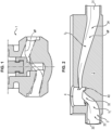
- valve tap 1 the general structure of a valve tap 1 in accordance with the state of the art is recognized. Also shown therein, superimposed and delimited by mixed lines, is the ideal fluid flow VF that it is desired to obtain using the tap according to the invention.
- fluid vein is meant throughout the present description, the volume delimited by the fluid which is called upon to circulate through the tap.
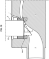
- FIG. 2 at least partly represents the body 2 of a tap 1 according to the invention.
- This body is crossed by a fluid circulation channel 3 which delimits the aforementioned fluid vein VF.
- the inlet and outlet of this channel are referenced respectively 30 and 31.
- the body 2 also comprises a second cylindrical channel 4, which is hereinafter referred to as "branch" 4 and which extends in a direction generally perpendicular to the channel 3.
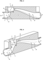
- Branch 4 is intended to receive the valve shutter, as can be seen in the figures 9 And 10 .
- the branch 4 extends to interfere with the channel 3 and has an annular bottom 40 which surrounds, that is to say surrounds the corresponding region of the channel 3.
- this channel 3 provided that it has, on either side of the region of action of the shutter, a generally circular liquid circulation section, which gradually connects, at least in the region of action of said shutter, to a section longer than it is wide, i.e. "flattened” (for example oblong or elliptical), the largest dimension of this section extending substantially perpendicular to the axis of the channel 4, and that the body 2 is devoid of any element forming an inward projection of channel 3, then the pressure losses of such a valve are drastically reduced.
- a generally circular liquid circulation section which gradually connects, at least in the region of action of said shutter, to a section longer than it is wide, i.e. "flattened” (for example oblong or elliptical), the largest dimension of this section extending substantially perpendicular to the axis of the channel 4, and that the body 2 is devoid of any element forming an inward projection of channel 3, then the pressure losses of such a valve are drastically reduced.
- the expression "shutter action region” means the zone 32 of channel 3 which interferes with branch 4.
- Channel 3 has an upward slope in the region of action of said shutter, i.e. in zone 32. They are also so because the channel has a first inflection upstream of zone 32 of upward slope and a second inflection downstream of zone 32 of downward slope, the terms "upstream” and "downstream” being considered taking into account the direction of flow of a fluid.
- the fluid vein VF obtained using the tap according to the present invention.
- the references VF1 and VF3 identify the circular sections of the vein, while the reference VF2 identifies the "flattened" section of the vein.
- the tap body 2 is equipped with a ring-shaped seat 6.
- a seat is made of a material such as stainless steel.
- This seat is sized in such a way that it can be positioned in the aforementioned annular bottom 40 of the branch 4, while ensuring perfect sealing.
- the opposite faces 62 and 63 of the body 60 of this seat are flat and parallel. However, with regard to the upper face 62, it is noted that it extends in the direction of the central opening 61, by a beveled peripheral flank 64 forming a sealing surface (as will be seen later). Of course, other shapes can be envisaged.
- This seat 6 is advantageously removable, but it can also be conceived that it is permanently fixed to the body 2.
- a cage 7 which, like the latter, has an annular shape. Its external diameter is strictly identical to that of the seat 6 and its upper and lower faces 73 and 74 are flat and parallel. Its internal diameter is, for its part, dimensioned in such a way that it coincides (i.e. is aligned) with the birth of the beveled flank 64 of the seat 6. In an embodiment not shown, the aforementioned external diameters are not identical.
- This body 50 of cylindrical shape, has a diameter identical, apart from the clearance, to the internal diameter of the cage 70.
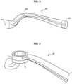
- the body 50 is extended by a spout 51 which fits into a cylinder of diameter smaller than that of the body 50.
- the annular shoulder 52 which separates them is also beveled and constitutes a second sealing surface, as will be explained later.
- the free end 510 of the spout 51 is beveled and is shaped so as to match, as much as possible, the curvature of the channel 3 in this region of the tap 1.
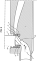
- the shutter 5 is shown in a position which allows the passage of fluid into the channel 3.
- the spout 51 is partially engaged in the seat 6.
- the fluid F (see arrows on the Figures 8 And 9 ) flowing through the tap "slides” undisturbed in its flow along the end 510 of the spout 51, passes through the central opening 61 of the seat then that 71 of the cage 7, to finally escape through the passage 72.
- the passage 72 has a shape similar and preferably identical to the section of the channel 3 in this region.
- the invention reduces the size of the valve required, which reduces all associated costs: actuators, pipes, support, space required, maintenance, etc. In addition, due to its reduced size, such a valve more easily retains its operability, even after an earthquake has occurred.
- the initial flow rate of the tap is maintained, despite the smaller passage section.
- Such taps can therefore be smaller in size, for the same nominal flow rate.
Landscapes
- Engineering & Computer Science (AREA)
- General Engineering & Computer Science (AREA)
- Mechanical Engineering (AREA)
- Lift Valve (AREA)
Claims (6)
- Absperrventil (1), das einen Körper (2), der von einem Fluidzirkulationskanal (3) durchquert wird, der eine Fluidader (VF) mit einem Einlass und einem Auslass begrenzt, sowie einen Verschluss (5) aufweist, der im Inneren einer im Allgemeinen senkrecht zum Körper verlaufenden Abzweigung (4) untergebracht ist, wobei dieser Verschluss (5) zwischen einer ersten Extremposition, in der er den Kanal (3) verschließt, und einer zweiten Extremposition, in der er den Kanal (3) nicht verschließt, beweglich ist, wobei das Absperrventil einen ringförmigen Sitz (6) aufweist, dessen zentrale Öffnung (61) bestimmt ist, von der Fluidader (VF) durchquert zu werden, dadurch gekennzeichnet, dass der Kanal (3) auf beiden Seiten des Wirkungsbereichs (32) des Verschlusses (5), das heißt, der Zone des Kanals (3), die mit der Abzweigung (4) interferiert, einen im Allgemeinen kreisförmigen Flüssigkeitszirkulationsabschnitt aufweist, der sich zumindest im Wirkungsbereich (32) des Verschlusses (5) kontinuierlich an einen Abschnitt anschließt, der länger als breit, das heißt abgeflacht ist, wobei der Körper (2) kein Element aufweist, das in das Innere des Kanals (3) vorspringt, und der Verschluss (5) ein freies Ende in Form eines Schnabels (51) aufweist das heißt allgemein abgeschrägt, und dabei teilweise in den Sitz (6) derart eingreift, dass die Kontinuität der Wand des Kanals (3) in Zirkulationsposition des Fluids gesichert ist.
- Absperrventil (1) nach Anspruch 1, dadurch gekennzeichnet, dass der Kanal (3) im Wirkungsbereich (32) des Verschlusses (5) eine ansteigende Neigung aufweist.
- Absperrventil (1) nach Anspruch 2, dadurch gekennzeichnet, dass der Kanal (3) einen ersten Knick (I1), der dem Bereich mit ansteigender Neigung vorgelagert ist, und einen zweiten Knick (I2), der dem Bereich mit ansteigender Neigung nachgelagert ist, aufweist, wobei die Begriffe "vorgelagert" und "nachgelagert" unter Berücksichtigung der Strömungsrichtung eines Fluids betrachtet werden.
- Absperrventil (1) nach einem der Ansprüche 1 bis 3, dadurch gekennzeichnet, dass es einen Käfig (7) zur Führung des Verschlusses (5) und zum Halten seines Sitzes (6) aufweist und dass dieser Käfig (7) eine ringförmige Form aufweist, dessen Wand einen Zirkulationsdurchgang (72) der Fluidader (VP) aufweist, der eine Form und eine Ausrichtung analog zu denen des längeren als breiten Abschnitts hat, das heißt abgeflacht ist.
- Absperrventil (1) nach einem der Ansprüche 1 bis 4, dadurch gekennzeichnet, dass der Sitz (6) und der Käfig (7) abnehmbar sind.
- Absperrventil (1) nach einem der Ansprüche 1 bis 4, dadurch gekennzeichnet, dass der Sitz (6) und der Käfig (7) nicht abnehmbar sind.
Applications Claiming Priority (2)
| Application Number | Priority Date | Filing Date | Title |
|---|---|---|---|
| FR1906817A FR3097608B1 (fr) | 2019-06-24 | 2019-06-24 | Robinet à soupape |
| PCT/EP2020/067472 WO2020260264A1 (fr) | 2019-06-24 | 2020-06-23 | Robinet a soupape |
Publications (2)
| Publication Number | Publication Date |
|---|---|
| EP3987202A1 EP3987202A1 (de) | 2022-04-27 |
| EP3987202B1 true EP3987202B1 (de) | 2024-10-09 |
Family
ID=68501716
Family Applications (1)
| Application Number | Title | Priority Date | Filing Date |
|---|---|---|---|
| EP20733640.5A Active EP3987202B1 (de) | 2019-06-24 | 2020-06-23 | Absperrventil |
Country Status (6)
| Country | Link |
|---|---|
| US (1) | US20220349481A1 (de) |
| EP (1) | EP3987202B1 (de) |
| CN (1) | CN114051568A (de) |
| CA (1) | CA3144688A1 (de) |
| FR (1) | FR3097608B1 (de) |
| WO (1) | WO2020260264A1 (de) |
Families Citing this family (1)
| Publication number | Priority date | Publication date | Assignee | Title |
|---|---|---|---|---|
| CN114542738A (zh) * | 2022-03-11 | 2022-05-27 | 西安热工研究院有限公司 | 一种微孔式流量电动调节阀 |
Family Cites Families (15)
| Publication number | Priority date | Publication date | Assignee | Title |
|---|---|---|---|---|
| CH197056A (de) * | 1937-05-12 | 1938-04-15 | Metallgiesserei & Armaturenfabrik Lyss | Durchgangsventil. |
| FI20049A (fi) * | 1937-07-24 | 1944-04-11 | Nordiska Armaturfab Ab | Anordning vid ventiler |
| US2685426A (en) * | 1949-06-15 | 1954-08-03 | Edward Valves Inc | Valve body with material flow guide and inclined seat structure |
| US3648718A (en) * | 1970-06-01 | 1972-03-14 | Foxboro Co | Valve structure |
| KR100280893B1 (ko) * | 1998-07-14 | 2001-11-02 | 권갑주 | 밸브의 유체흐름 제어장치 |
| US6250330B1 (en) * | 1999-11-08 | 2001-06-26 | Welker Engineering Company | Diaphragm regulator with removable diffuser |
| US6213150B1 (en) * | 2000-04-18 | 2001-04-10 | Fisher Controls International, Inc. | Fluid pressure reduction disks with taper nut retention device |
| US7458393B2 (en) * | 2006-03-28 | 2008-12-02 | Bermad Cs, Ltd | Control valve with integrated insert providing valve seat and plug guides |
| US20090026395A1 (en) * | 2007-07-25 | 2009-01-29 | Aaron Andrew Perrault | Apparatus to increase fluid flow in a valve |
| US7854239B2 (en) * | 2008-03-03 | 2010-12-21 | Fisher Controls International Llc | High temperature valve |
| WO2012112845A1 (en) * | 2011-02-17 | 2012-08-23 | Egc Interprises, Inc. | Control valve assembly |
| IL213412A (en) * | 2011-06-06 | 2015-06-30 | Eliyaho Dvash | A rigid sealable hydraulic control valve with an elliptical design flow pass |
| US9267604B2 (en) * | 2013-03-14 | 2016-02-23 | Fisher Controls International Llc | Valve seat apparatus for use with fluid valves |
| DE202017103236U1 (de) * | 2017-05-30 | 2017-07-28 | Samson Ag | Ventilgehäuse und damit ausgestattetes Ventil |
| DE102017123396A1 (de) * | 2017-10-09 | 2019-04-11 | Samson Aktiengesellschaft | Hubventil und Anordnung für ein Hubventil |
-
2019
- 2019-06-24 FR FR1906817A patent/FR3097608B1/fr active Active
-
2020
- 2020-06-23 WO PCT/EP2020/067472 patent/WO2020260264A1/fr not_active Ceased
- 2020-06-23 EP EP20733640.5A patent/EP3987202B1/de active Active
- 2020-06-23 CN CN202080046796.8A patent/CN114051568A/zh active Pending
- 2020-06-23 US US17/621,522 patent/US20220349481A1/en not_active Abandoned
- 2020-06-23 CA CA3144688A patent/CA3144688A1/fr active Pending
Also Published As
| Publication number | Publication date |
|---|---|
| FR3097608A1 (fr) | 2020-12-25 |
| WO2020260264A1 (fr) | 2020-12-30 |
| EP3987202A1 (de) | 2022-04-27 |
| US20220349481A1 (en) | 2022-11-03 |
| CN114051568A (zh) | 2022-02-15 |
| CA3144688A1 (fr) | 2020-12-30 |
| FR3097608B1 (fr) | 2021-09-17 |
Similar Documents
| Publication | Publication Date | Title |
|---|---|---|
| FR2493461A1 (fr) | Dispositif de vanne a bille | |
| CH671816A5 (de) | ||
| FR2521678A1 (fr) | Clapet spherique de type perfectionne comprenant un siege d'amont et un siege d'aval | |
| EP1048997A1 (de) | Kartusche für ein Mischventil mit Temperaturbegrenzung | |
| EP3987202B1 (de) | Absperrventil | |
| FR2552192A1 (fr) | Vanne a passage direct | |
| FR2892791A1 (fr) | Dispositifs de perte de charge variable et/ou de fermeture et d'etancheite a cartouche interne et tube mobile | |
| WO2015170042A1 (fr) | Insert de decompression pour vanne rotative et vanne rotative equipee d'un tel insert | |
| FR2853947A1 (fr) | Dispositif a clapet de regulation du debit d'un fluide | |
| FR2917799A1 (fr) | Vanne a longue course de regulation avec fonction d'arret. | |
| EP3488311B1 (de) | Mischeinheit und mischarmatur mit solch einer mischeinheit | |
| EP3446192B1 (de) | Mischeinheit und mischarmatur mit solch einer mischeinheit | |
| FR2828547A3 (fr) | Soupape de securite a double fonction | |
| LU82708A1 (fr) | Vanne a obturateur equilibre | |
| EP3177571B1 (de) | Wasserbehandlungsvorrichtung mit hoher kapazität | |
| EP4305328A1 (de) | Expansionsventil mit einem beweglichen schieber | |
| FR2957709A1 (fr) | Obturateur pour conduit de fluide de reacteur nucleaire, notamment pour drain de fond de generateur de vapeur | |
| CA2797332C (fr) | Robinet a joint metallique | |
| FR2664351A3 (fr) | Vanne papillon. | |
| FR2970055A1 (fr) | Dispositif d'etancheite par siege-annulaire | |
| EP3775645B1 (de) | Verbessertes regelventil mit integrierter spülfunktion | |
| EP1069354A1 (de) | Rückflussverhinder | |
| FR3156878A1 (fr) | Dispositif d’arrêt d’un débit de fuite sur une canalisation de fluide | |
| FR2771154A1 (fr) | Soupape de securite | |
| FR3156879A1 (fr) | Dispositif d’arrêt d’un débit de fuite sur une canalisation de fluide |
Legal Events
| Date | Code | Title | Description |
|---|---|---|---|
| STAA | Information on the status of an ep patent application or granted ep patent |
Free format text: STATUS: UNKNOWN |
|
| STAA | Information on the status of an ep patent application or granted ep patent |
Free format text: STATUS: THE INTERNATIONAL PUBLICATION HAS BEEN MADE |
|
| PUAI | Public reference made under article 153(3) epc to a published international application that has entered the european phase |
Free format text: ORIGINAL CODE: 0009012 |
|
| STAA | Information on the status of an ep patent application or granted ep patent |
Free format text: STATUS: REQUEST FOR EXAMINATION WAS MADE |
|
| 17P | Request for examination filed |
Effective date: 20220117 |
|
| AK | Designated contracting states |
Kind code of ref document: A1 Designated state(s): AL AT BE BG CH CY CZ DE DK EE ES FI FR GB GR HR HU IE IS IT LI LT LU LV MC MK MT NL NO PL PT RO RS SE SI SK SM TR |
|
| DAV | Request for validation of the european patent (deleted) | ||
| DAX | Request for extension of the european patent (deleted) | ||
| STAA | Information on the status of an ep patent application or granted ep patent |
Free format text: STATUS: EXAMINATION IS IN PROGRESS |
|
| 17Q | First examination report despatched |
Effective date: 20231121 |
|
| GRAP | Despatch of communication of intention to grant a patent |
Free format text: ORIGINAL CODE: EPIDOSNIGR1 |
|
| STAA | Information on the status of an ep patent application or granted ep patent |
Free format text: STATUS: GRANT OF PATENT IS INTENDED |
|
| INTG | Intention to grant announced |
Effective date: 20240513 |
|
| GRAS | Grant fee paid |
Free format text: ORIGINAL CODE: EPIDOSNIGR3 |
|
| GRAA | (expected) grant |
Free format text: ORIGINAL CODE: 0009210 |
|
| STAA | Information on the status of an ep patent application or granted ep patent |
Free format text: STATUS: THE PATENT HAS BEEN GRANTED |
|
| AK | Designated contracting states |
Kind code of ref document: B1 Designated state(s): AL AT BE BG CH CY CZ DE DK EE ES FI FR GB GR HR HU IE IS IT LI LT LU LV MC MK MT NL NO PL PT RO RS SE SI SK SM TR |
|
| REG | Reference to a national code |
Ref country code: CH Ref legal event code: EP |
|
| REG | Reference to a national code |
Ref country code: DE Ref legal event code: R096 Ref document number: 602020039067 Country of ref document: DE |
|
| REG | Reference to a national code |
Ref country code: IE Ref legal event code: FG4D Free format text: LANGUAGE OF EP DOCUMENT: FRENCH |
|
| REG | Reference to a national code |
Ref country code: LT Ref legal event code: MG9D |
|
| REG | Reference to a national code |
Ref country code: NL Ref legal event code: MP Effective date: 20241009 |
|
| REG | Reference to a national code |
Ref country code: AT Ref legal event code: MK05 Ref document number: 1730915 Country of ref document: AT Kind code of ref document: T Effective date: 20241009 |
|
| PG25 | Lapsed in a contracting state [announced via postgrant information from national office to epo] |
Ref country code: NL Free format text: LAPSE BECAUSE OF FAILURE TO SUBMIT A TRANSLATION OF THE DESCRIPTION OR TO PAY THE FEE WITHIN THE PRESCRIBED TIME-LIMIT Effective date: 20241009 |
|
| PG25 | Lapsed in a contracting state [announced via postgrant information from national office to epo] |
Ref country code: NL Free format text: LAPSE BECAUSE OF FAILURE TO SUBMIT A TRANSLATION OF THE DESCRIPTION OR TO PAY THE FEE WITHIN THE PRESCRIBED TIME-LIMIT Effective date: 20241009 |
|
| PG25 | Lapsed in a contracting state [announced via postgrant information from national office to epo] |
Ref country code: HR Free format text: LAPSE BECAUSE OF FAILURE TO SUBMIT A TRANSLATION OF THE DESCRIPTION OR TO PAY THE FEE WITHIN THE PRESCRIBED TIME-LIMIT Effective date: 20241009 Ref country code: IS Free format text: LAPSE BECAUSE OF FAILURE TO SUBMIT A TRANSLATION OF THE DESCRIPTION OR TO PAY THE FEE WITHIN THE PRESCRIBED TIME-LIMIT Effective date: 20250209 Ref country code: PT Free format text: LAPSE BECAUSE OF FAILURE TO SUBMIT A TRANSLATION OF THE DESCRIPTION OR TO PAY THE FEE WITHIN THE PRESCRIBED TIME-LIMIT Effective date: 20250210 |
|
| PG25 | Lapsed in a contracting state [announced via postgrant information from national office to epo] |
Ref country code: FI Free format text: LAPSE BECAUSE OF FAILURE TO SUBMIT A TRANSLATION OF THE DESCRIPTION OR TO PAY THE FEE WITHIN THE PRESCRIBED TIME-LIMIT Effective date: 20241009 |
|
| PG25 | Lapsed in a contracting state [announced via postgrant information from national office to epo] |
Ref country code: BG Free format text: LAPSE BECAUSE OF FAILURE TO SUBMIT A TRANSLATION OF THE DESCRIPTION OR TO PAY THE FEE WITHIN THE PRESCRIBED TIME-LIMIT Effective date: 20241009 |
|
| PG25 | Lapsed in a contracting state [announced via postgrant information from national office to epo] |
Ref country code: ES Free format text: LAPSE BECAUSE OF FAILURE TO SUBMIT A TRANSLATION OF THE DESCRIPTION OR TO PAY THE FEE WITHIN THE PRESCRIBED TIME-LIMIT Effective date: 20241009 |
|
| PG25 | Lapsed in a contracting state [announced via postgrant information from national office to epo] |
Ref country code: NO Free format text: LAPSE BECAUSE OF FAILURE TO SUBMIT A TRANSLATION OF THE DESCRIPTION OR TO PAY THE FEE WITHIN THE PRESCRIBED TIME-LIMIT Effective date: 20250109 |
|
| PG25 | Lapsed in a contracting state [announced via postgrant information from national office to epo] |
Ref country code: LV Free format text: LAPSE BECAUSE OF FAILURE TO SUBMIT A TRANSLATION OF THE DESCRIPTION OR TO PAY THE FEE WITHIN THE PRESCRIBED TIME-LIMIT Effective date: 20241009 Ref country code: GR Free format text: LAPSE BECAUSE OF FAILURE TO SUBMIT A TRANSLATION OF THE DESCRIPTION OR TO PAY THE FEE WITHIN THE PRESCRIBED TIME-LIMIT Effective date: 20250110 Ref country code: AT Free format text: LAPSE BECAUSE OF FAILURE TO SUBMIT A TRANSLATION OF THE DESCRIPTION OR TO PAY THE FEE WITHIN THE PRESCRIBED TIME-LIMIT Effective date: 20241009 |
|
| PG25 | Lapsed in a contracting state [announced via postgrant information from national office to epo] |
Ref country code: PL Free format text: LAPSE BECAUSE OF FAILURE TO SUBMIT A TRANSLATION OF THE DESCRIPTION OR TO PAY THE FEE WITHIN THE PRESCRIBED TIME-LIMIT Effective date: 20241009 |
|
| PG25 | Lapsed in a contracting state [announced via postgrant information from national office to epo] |
Ref country code: RS Free format text: LAPSE BECAUSE OF FAILURE TO SUBMIT A TRANSLATION OF THE DESCRIPTION OR TO PAY THE FEE WITHIN THE PRESCRIBED TIME-LIMIT Effective date: 20250109 |
|
| PG25 | Lapsed in a contracting state [announced via postgrant information from national office to epo] |
Ref country code: SM Free format text: LAPSE BECAUSE OF FAILURE TO SUBMIT A TRANSLATION OF THE DESCRIPTION OR TO PAY THE FEE WITHIN THE PRESCRIBED TIME-LIMIT Effective date: 20241009 |
|
| PG25 | Lapsed in a contracting state [announced via postgrant information from national office to epo] |
Ref country code: DK Free format text: LAPSE BECAUSE OF FAILURE TO SUBMIT A TRANSLATION OF THE DESCRIPTION OR TO PAY THE FEE WITHIN THE PRESCRIBED TIME-LIMIT Effective date: 20241009 |
|
| REG | Reference to a national code |
Ref country code: DE Ref legal event code: R097 Ref document number: 602020039067 Country of ref document: DE |
|
| PG25 | Lapsed in a contracting state [announced via postgrant information from national office to epo] |
Ref country code: EE Free format text: LAPSE BECAUSE OF FAILURE TO SUBMIT A TRANSLATION OF THE DESCRIPTION OR TO PAY THE FEE WITHIN THE PRESCRIBED TIME-LIMIT Effective date: 20241009 |
|
| PGFP | Annual fee paid to national office [announced via postgrant information from national office to epo] |
Ref country code: FR Payment date: 20250513 Year of fee payment: 6 |
|
| PG25 | Lapsed in a contracting state [announced via postgrant information from national office to epo] |
Ref country code: RO Free format text: LAPSE BECAUSE OF FAILURE TO SUBMIT A TRANSLATION OF THE DESCRIPTION OR TO PAY THE FEE WITHIN THE PRESCRIBED TIME-LIMIT Effective date: 20241009 |
|
| PG25 | Lapsed in a contracting state [announced via postgrant information from national office to epo] |
Ref country code: SK Free format text: LAPSE BECAUSE OF FAILURE TO SUBMIT A TRANSLATION OF THE DESCRIPTION OR TO PAY THE FEE WITHIN THE PRESCRIBED TIME-LIMIT Effective date: 20241009 |
|
| PG25 | Lapsed in a contracting state [announced via postgrant information from national office to epo] |
Ref country code: CZ Free format text: LAPSE BECAUSE OF FAILURE TO SUBMIT A TRANSLATION OF THE DESCRIPTION OR TO PAY THE FEE WITHIN THE PRESCRIBED TIME-LIMIT Effective date: 20241009 |
|
| PG25 | Lapsed in a contracting state [announced via postgrant information from national office to epo] |
Ref country code: IT Free format text: LAPSE BECAUSE OF FAILURE TO SUBMIT A TRANSLATION OF THE DESCRIPTION OR TO PAY THE FEE WITHIN THE PRESCRIBED TIME-LIMIT Effective date: 20241009 |
|
| PLBE | No opposition filed within time limit |
Free format text: ORIGINAL CODE: 0009261 |
|
| STAA | Information on the status of an ep patent application or granted ep patent |
Free format text: STATUS: NO OPPOSITION FILED WITHIN TIME LIMIT |
|
| PG25 | Lapsed in a contracting state [announced via postgrant information from national office to epo] |
Ref country code: SE Free format text: LAPSE BECAUSE OF FAILURE TO SUBMIT A TRANSLATION OF THE DESCRIPTION OR TO PAY THE FEE WITHIN THE PRESCRIBED TIME-LIMIT Effective date: 20241009 |
|
| 26N | No opposition filed |
Effective date: 20250710 |
|
| REG | Reference to a national code |
Ref country code: DE Ref legal event code: R119 Ref document number: 602020039067 Country of ref document: DE |
|
| REG | Reference to a national code |
Ref country code: CH Ref legal event code: H13 Free format text: ST27 STATUS EVENT CODE: U-0-0-H10-H13 (AS PROVIDED BY THE NATIONAL OFFICE) Effective date: 20260127 |
|
| PG25 | Lapsed in a contracting state [announced via postgrant information from national office to epo] |
Ref country code: MC Free format text: LAPSE BECAUSE OF FAILURE TO SUBMIT A TRANSLATION OF THE DESCRIPTION OR TO PAY THE FEE WITHIN THE PRESCRIBED TIME-LIMIT Effective date: 20241009 |
|
| PG25 | Lapsed in a contracting state [announced via postgrant information from national office to epo] |
Ref country code: LU Free format text: LAPSE BECAUSE OF NON-PAYMENT OF DUE FEES Effective date: 20250623 |
|
| GBPC | Gb: european patent ceased through non-payment of renewal fee |
Effective date: 20250623 |
|
| REG | Reference to a national code |
Ref country code: BE Ref legal event code: MM Effective date: 20250630 |