EP3987100B1 - A presser foot module for a tufting machine - Google Patents
A presser foot module for a tufting machine Download PDFInfo
- Publication number
- EP3987100B1 EP3987100B1 EP20734484.7A EP20734484A EP3987100B1 EP 3987100 B1 EP3987100 B1 EP 3987100B1 EP 20734484 A EP20734484 A EP 20734484A EP 3987100 B1 EP3987100 B1 EP 3987100B1
- Authority
- EP
- European Patent Office
- Prior art keywords
- fingers
- module
- finger
- tufting machine
- presser foot
- Prior art date
- Legal status (The legal status is an assumption and is not a legal conclusion. Google has not performed a legal analysis and makes no representation as to the accuracy of the status listed.)
- Active
Links
- 238000009732 tufting Methods 0.000 title claims description 35
- 235000014676 Phragmites communis Nutrition 0.000 description 3
- 244000273256 Phragmites communis Species 0.000 description 2
- 230000004048 modification Effects 0.000 description 2
- 238000012986 modification Methods 0.000 description 2
- 238000013459 approach Methods 0.000 description 1
- 230000004888 barrier function Effects 0.000 description 1
- 238000007689 inspection Methods 0.000 description 1
- 239000000463 material Substances 0.000 description 1
- 230000000717 retained effect Effects 0.000 description 1
- 239000011435 rock Substances 0.000 description 1
- 238000000926 separation method Methods 0.000 description 1
Images


Classifications
-
- D—TEXTILES; PAPER
- D05—SEWING; EMBROIDERING; TUFTING
- D05C—EMBROIDERING; TUFTING
- D05C15/00—Making pile fabrics or articles having similar surface features by inserting loops into a base material
- D05C15/04—Tufting
- D05C15/08—Tufting machines
-
- D—TEXTILES; PAPER
- D05—SEWING; EMBROIDERING; TUFTING
- D05C—EMBROIDERING; TUFTING
- D05C15/00—Making pile fabrics or articles having similar surface features by inserting loops into a base material
- D05C15/04—Tufting
- D05C15/08—Tufting machines
- D05C15/14—Arrangements or devices for holding or feeding the base material
-
- D—TEXTILES; PAPER
- D05—SEWING; EMBROIDERING; TUFTING
- D05C—EMBROIDERING; TUFTING
- D05C15/00—Making pile fabrics or articles having similar surface features by inserting loops into a base material
- D05C15/04—Tufting
- D05C15/08—Tufting machines
- D05C15/16—Arrangements or devices for manipulating threads
-
- D—TEXTILES; PAPER
- D05—SEWING; EMBROIDERING; TUFTING
- D05C—EMBROIDERING; TUFTING
- D05C15/00—Making pile fabrics or articles having similar surface features by inserting loops into a base material
- D05C15/04—Tufting
- D05C15/08—Tufting machines
- D05C15/10—Tufting machines operating with a plurality of needles, e.g. in one row
-
- D—TEXTILES; PAPER
- D05—SEWING; EMBROIDERING; TUFTING
- D05C—EMBROIDERING; TUFTING
- D05C15/00—Making pile fabrics or articles having similar surface features by inserting loops into a base material
- D05C15/04—Tufting
- D05C15/08—Tufting machines
- D05C15/16—Arrangements or devices for manipulating threads
- D05C15/22—Loop-catching arrangements, e.g. loopers; Driving mechanisms therefor
Definitions
- the present invention relates to a presser foot module for a tufting machine.
- a presser foot module is a gauge part of a tufting machine.
- the modules are attached to a presser foot bar. This is a bar which is mounted immediately above the backing medium which is fed through a tufting machine.
- the presser foot module is distinct from other tufting machine gauge parts such as the hooks, needles and reeds.
- a conventional presser foot module comprises two main parts, namely a module body and a plurality of fingers extending from the body.
- the module body is provided with an opening via which the module is mounted to the presser foot bar.
- the underside of the body acts as a presser surface pressing yarns against the rear face of the backing medium following after the yarns have been tufted into the backing medium.
- the presser foot exerts a pressure on these to ensure that they are kept roughly in the right position such that any interference with adjacent yarns is minimised without the yarns being lost out of the needle eye.
- a plurality of fingers protrude. These have a flat plate like structure and protrude from the module body in a direction which, in use, is opposite to the direction in which the backing medium is fed through the tufting machine.
- the fingers have a relatively longitudinal dimension and therefore, in order to prevent them from being deflected and distorted in use as they move sideways with the needle bar, a bar extends across the distal end of the fingers to enhance rigidity. This creates a number of gaps between the module body, two adjacent fingers and the bar at the distal end through which, in use, a needle of a tufting machine reciprocates in order to form a tuft in the carpet.
- the fingers provide barriers in order to separate the yarn from the yarn of an adjacent needle so as to minimise cross stitching.
- the needles are reciprocated in and out of the gap between an adjacent pair of fingers. This causes a problem in that yarn can become trapped between the fingers and the needles. This is less of a problem in a cut pile yarn where the tensions are higher.
- the loops are more sensitive to trapping between the fingers and the needles because the loops are released from the hooks each time a loop is formed rather than remaining wrapped around the looper for a cut pile.
- the present invention aims at improving the design of the presser foot to address these problems.
- GB1120038 and JP S58-203152 disclose a presser foot module according to the preamble of claim 1. According to a first aspect of the invention, such a module is characterised by the characterising feature of claim 1.
- the lip provides a presser surface which is significantly narrower than the presser surface of the prior art which has no such lip.
- the presser foot allows a higher pressure to be applied to the yarn across a narrower and more controlled area. This higher pressure provides better holding of the yarn in that area.
- the total frictional load applied to the yarn can be significantly lower as the yarn is in contact with the presser foot for a much shorter proportion of its travel. This reduces the possibility of damaging the yarn.
- the invention provides improved yarn control and reduced damage.
- the lip is relatively narrow.
- the dimension of the downwardly depending lip in the first direction is less than 1.5 times the pitch of the fingers and more preferably, is less than the pitch of the fingers.
- the pitch of the fingers represents the separation between adjacent fingers.
- the dimension of the downwardly depending lip in the first direction is greater than 0.5 times the pitch of the fingers.
- the lower edge of each finger has a groove. This helps to keep the yarn in place in a controlled position which is away from any stitch location of a subsequent stitch
- each finger In a presser foot module, the fingers typically do not extend below the presser surface, unlike in a hook module where the hooks extend beyond the surface of the body which is opposite to the side which is attached to the tufting machine.
- at least part of the lower edge of each finger is typically greater than 0.5 mm and preferably at least 1 mm above the presser surface. This is different from the bed plate where the tops of the reeds are as close as possible to the top of the body as these are required to support the backing medium.
- each finger In a presser foot module, each finger is typically formed as a single planar component in a plane transverse to the presser surface. This is fundamentally different from the scissor like mechanism of JPH11124764 in which two comb like structures with sharp edges slide relatively to one another to shear fluff.
- the fingers may have a bar running across the distal end of the fingers to support them at this end.
- each finger has a first end mounted in the module body and a second end opposite to the first end which is unsupported so as to provide access to an open gap between adjacent fingers in a direction opposite to the first direction.
- Such a module provides an advantage over a conventional module that access into the gap between the adjacent teeth is in a direction opposite to the first direction thereby allowing much easier rethreading of a the tufting machine as it is no longer necessary to feed each loose end of yarn downwardly through a gap between adjacent fingers.
- the present invention allows for enhanced inspection of the threading up of a tufting machine as the bar in the prior art obstructs the view into the tufting region of the machine.
- JP H-11 124764 discloses a presser foot module for a tufting machine, the module having a module body with a first side for attachment to a tufting machine and a plurality of fingers extending from the body in a first direction which, in use, is opposite to the direction in which the backing medium is fed through the tufting machine, each finger having a second end opposite to a first end which is unsupported so as to provide access to an open gap between adjacent fingers in a direction opposite to the first direction the module having a second side opposite to the first side provided with a presser surface extending across the body to engage in use, with a backing medium fed through the tufting machine; wherein the fingers do not extend below the presser surface and at least part of the lower edge of each finger is above the presser surface (figure 4).
- the module of the prior art needs to the fingers to be relatively long in order that the bar does not obstruct the reciprocation of the needles.
- the fingers can be significantly shorter.
- the maximum length of the finger to the pitch of the fingers is less than 4, preferably less than 3.5 and most preferably less than 3.
- the shorter fingers are less prone to deflection than the fingers of the prior art.
- the support provided by the bar is no longer required for these smaller fingers thereby leading to a synergy between the absence of the bar and the shorter fingers.
- the present invention also extends to a tufting machine or a presser foot bar to which a plurality of modules according to aspects of the invention set out above are attached.
- the invention also extends to a tufting machine comprising at least one presser foot module as set out above.
- the tufting machine shown in Fig. 1 is, in almost every respect, a known individual needle control (ICN) machine. As this is largely conventional, the main components will be described briefly here.
- ICN individual needle control
- the backing medium 1 (depicted schematically as a dashed line in Fig. 1 ) is fed through the tufting machine in a feed direction depicted by arrow 2 and is supported in the tufting position by a bed plate 3.
- a needle bar 4 supports a line of needles 5 (the line extending in the direction perpendicular to the plane of Fig. 1 ).
- Each needle 5 is supported on a needle support 6.
- Each needle support 6 has an associated latch 7 such that, if the needle 5 is required to be reciprocated in a particular stroke, the needle 5 can be selectively latched to the needle bar 4 so that it will penetrate the backing medium 1 to form a loop of yarn.
- This is well-known in the art as an individual needle control (ICN) machine.
- the loopers 8 will rock forwards to pick up a loop of yarn formed by the needle 5.
- the loopers are preferably level cut loopers (LCL), these have a latching mechanism which is configured either to ensure that the loop of yarn slips off of the looper 8 or alternatively to ensure that it is retained on the looper 8 such that it slides back to a throat 9 of the looper and is cut by a respective knife 10 in order to form a cut pile tuft.
- This mechanism is therefore capable of selectively forming loop or cut pile tufts. Further details of a level cut looper are disclosed, for example, in GB 2367305 or GB 2354263 .
- a presser foot 11 is provided in order to support the backing medium 1 as the needles 5 are pulled through it in the upwards direction in Fig. 1 .
- the presser foot comprises a plurality of fingers 12 and a mounting body 13.
- the presser module can also be used on a conventional tufting machine.
- the presser foot module is shown in greater detail in Figs. 2B and 3 . These show one module 50 of the presser foot. As described above, this has a mounting body 13 from which a plurality of fingers 12 project in a direction opposite to the direction 2 in which the backing medium 1 is fed through the tufting machine. The body 13 is provided with a mounting hole 51 by which the presser foot module 50 is mounted to a presser foot bar 52 ( Fig. 1 ) which is mounted to slide laterally together with the needle bar, but does not reciprocate with the needle bar in the direction of reciprocation of the needles. Instead, it remains in the position shown in Fig. 1 immediately above the backing medium 1.
- the module 50 has three unconventional features.
- a bar 60 extends across the distal end of the figures 12' in order to provide enhanced rigidity.
- Fig. 2B no such bar is present such that there is an open gap at the distal of the fingers 12. This improves the rethreading of the tufting machine as, when passing a yarn through the presser foot, this can be done by moving the yarn laterally between two fingers 12, rather than having two thread a cut end from top to bottom as previously. The replacement of a module is also easier.
- the second modification is the presence of a downwardly depending lip 53 which extends across the module 50 in a downward direction (i.e. in a direction away from the service which is mounted to the presser foot bar 52) such that, in use, only this lip 53 engages with the yarns.
- a downwardly depending lip 53 which extends across the module 50 in a downward direction (i.e. in a direction away from the service which is mounted to the presser foot bar 52) such that, in use, only this lip 53 engages with the yarns.
- the presser surface 53A provided on the lower face of the lip 53 is significantly narrower than the presser surface 53B of the prior art and there is a wide region 53C behind the lip 53 where the yarns do not engage with the presser foot module.
- the fingers 12 have been shortened.
- the ratio of the maximum length of a finger to the pitch of the fingers has been reduced from 4.3 to less than 4, more preferably less than 3.5 and most preferably less than 3. This saves material and reduces weight. Now that the bar is no longer required, the size of the opening between adjacent fingers is no longer an issue in the threading operation.
- each finger 12 has a groove 14 which represents a region where the lower edge is spaced further from the backing medium 1.
- the finger therefore has a position of minimum height part way along its length and increases in height in both directions away from that position.
- the yarns extend down between adjacent fingers and the portions of the yarn which end up on the rear surface of the backing medium 1 then slide under the module body 13.
- the groove 14 allows the yarn to pass readily beneath the lower edge of the finger 12 and helps to keep it in place in a controlled position which is away from any stitch location of a subsequent stitch.
- the yarns By providing the lip 53, rather than the yarn engaging surface across a wide portion of the module 13, the yarns only engage under the lip leading to a reduced frictional force between the presser foot and the yarn. Also, as the lip 53 represents a single line of contact between the presser foot and the yarn, it is easier to control the amount of pressure on the yarn. Control of this pressure is important and it requires a balance between creating a pressure which is high enough to ensure that the loose ends of yarn stay under the presser foot, but which is not high enough to generate undue friction on the yarns.
Description
- The present invention relates to a presser foot module for a tufting machine.
- A presser foot module is a gauge part of a tufting machine. The modules are attached to a presser foot bar. This is a bar which is mounted immediately above the backing medium which is fed through a tufting machine. The presser foot module is distinct from other tufting machine gauge parts such as the hooks, needles and reeds.
- Broadly, a conventional presser foot module comprises two main parts, namely a module body and a plurality of fingers extending from the body. The module body is provided with an opening via which the module is mounted to the presser foot bar. The underside of the body acts as a presser surface pressing yarns against the rear face of the backing medium following after the yarns have been tufted into the backing medium. In this region, there will be a number of yarns which have not been tufted into the backing medium and the presser foot exerts a pressure on these to ensure that they are kept roughly in the right position such that any interference with adjacent yarns is minimised without the yarns being lost out of the needle eye.
- From the module body, a plurality of fingers protrude. These have a flat plate like structure and protrude from the module body in a direction which, in use, is opposite to the direction in which the backing medium is fed through the tufting machine. The fingers have a relatively longitudinal dimension and therefore, in order to prevent them from being deflected and distorted in use as they move sideways with the needle bar, a bar extends across the distal end of the fingers to enhance rigidity. This creates a number of gaps between the module body, two adjacent fingers and the bar at the distal end through which, in use, a needle of a tufting machine reciprocates in order to form a tuft in the carpet. The fingers provide barriers in order to separate the yarn from the yarn of an adjacent needle so as to minimise cross stitching.
- In use, the needles are reciprocated in and out of the gap between an adjacent pair of fingers. This causes a problem in that yarn can become trapped between the fingers and the needles. This is less of a problem in a cut pile yarn where the tensions are higher. However, in a loop pile carpet, the loops are more sensitive to trapping between the fingers and the needles because the loops are released from the hooks each time a loop is formed rather than remaining wrapped around the looper for a cut pile.
- This can also be a problem for an LCL machine (which forms a combination of loop and cut piles) where the same problems arise for the loop piles. The Applicant has tried many different approaches to try to resolve the problem of snagging of yarns on the fingers. For example, we have tried improving the pitch accuracy of the needles and needle holders, using thinner needles, reducing the needle rack, changing the reed finger profile, changing the hook profile and changing the yarn delivery profile.
- There is also a problem that, in order to maintain the yarns under the presser foot, a reasonably high pressure is required. However, this provides increased frictional forces on the yarn which can damage the yarn.
- The present invention aims at improving the design of the presser foot to address these problems.
-
GB1120038 JP S58-203152 claim 1. According to a first aspect of the invention, such a module is characterised by the characterising feature ofclaim 1. - The lip provides a presser surface which is significantly narrower than the presser surface of the prior art which has no such lip. As result of this, the presser foot allows a higher pressure to be applied to the yarn across a narrower and more controlled area. This higher pressure provides better holding of the yarn in that area. However, despite this high pressure, the total frictional load applied to the yarn can be significantly lower as the yarn is in contact with the presser foot for a much shorter proportion of its travel. This reduces the possibility of damaging the yarn. Thus, the invention provides improved yarn control and reduced damage.
- The lip is relatively narrow. Preferably, the dimension of the downwardly depending lip in the first direction is less than 1.5 times the pitch of the fingers and more preferably, is less than the pitch of the fingers. The pitch of the fingers represents the separation between adjacent fingers.
- On the other hand, if the lip is too narrow, this can require too high a pressure to be concentrated over a relatively narrow area. Therefore, preferably, the dimension of the downwardly depending lip in the first direction is greater than 0.5 times the pitch of the fingers. Preferably the lower edge of each finger has a groove. This helps to keep the yarn in place in a controlled position which is away from any stitch location of a subsequent stitch
- In a presser foot module, the fingers typically do not extend below the presser surface, unlike in a hook module where the hooks extend beyond the surface of the body which is opposite to the side which is attached to the tufting machine. In a presser foot module, at least part of the lower edge of each finger is typically greater than 0.5 mm and preferably at least 1 mm above the presser surface. This is different from the bed plate where the tops of the reeds are as close as possible to the top of the body as these are required to support the backing medium. In a presser foot module, each finger is typically formed as a single planar component in a plane transverse to the presser surface. This is fundamentally different from the scissor like mechanism of
JPH11124764 - The fingers may have a bar running across the distal end of the fingers to support them at this end. However, preferably, each finger has a first end mounted in the module body and a second end opposite to the first end which is unsupported so as to provide access to an open gap between adjacent fingers in a direction opposite to the first direction. Such a module provides an advantage over a conventional module that access into the gap between the adjacent teeth is in a direction opposite to the first direction thereby allowing much easier rethreading of a the tufting machine as it is no longer necessary to feed each loose end of yarn downwardly through a gap between adjacent fingers. Further, the present invention allows for enhanced inspection of the threading up of a tufting machine as the bar in the prior art obstructs the view into the tufting region of the machine.
-
JP H-11 124764 - This provides a second aspect of the present invention which is a presser foot module according to
claim 10 and a tufting machine according toclaim 14. - The module of the prior art needs to the fingers to be relatively long in order that the bar does not obstruct the reciprocation of the needles. However, with the present invention, the fingers can be significantly shorter. Preferably, the maximum length of the finger to the pitch of the fingers is less than 4, preferably less than 3.5 and most preferably less than 3. The shorter fingers are less prone to deflection than the fingers of the prior art. The support provided by the bar is no longer required for these smaller fingers thereby leading to a synergy between the absence of the bar and the shorter fingers.
- The present invention also extends to a tufting machine or a presser foot bar to which a plurality of modules according to aspects of the invention set out above are attached. The invention also extends to a tufting machine comprising at least one presser foot module as set out above.
- An example of a presser foot module and a tufting machine in accordance with the present invention while now be described with reference to the accompanying drawings in which:
-
Fig. 1 is a side view of a tufting machine of the present invention; -
Fig. 2A is a view from below showing a conventional presser foot module; -
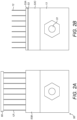
Fig. 2B is a similar view showing a presser foot module according to the present invention; and -
Fig. 3 is a perspective view of a presser foot module according to the invention. - The tufting machine shown in
Fig. 1 is, in almost every respect, a known individual needle control (ICN) machine. As this is largely conventional, the main components will be described briefly here. - The backing medium 1 (depicted schematically as a dashed line in
Fig. 1 ) is fed through the tufting machine in a feed direction depicted byarrow 2 and is supported in the tufting position by abed plate 3. Aneedle bar 4 supports a line of needles 5 (the line extending in the direction perpendicular to the plane ofFig. 1 ). Eachneedle 5 is supported on aneedle support 6. Eachneedle support 6 has an associated latch 7 such that, if theneedle 5 is required to be reciprocated in a particular stroke, theneedle 5 can be selectively latched to theneedle bar 4 so that it will penetrate thebacking medium 1 to form a loop of yarn. This is well-known in the art as an individual needle control (ICN) machine. - Beneath the
backing medium 1 is alooper 8 associated with eachneedle 5. Theloopers 8 will rock forwards to pick up a loop of yarn formed by theneedle 5. In this example, the loopers are preferably level cut loopers (LCL), these have a latching mechanism which is configured either to ensure that the loop of yarn slips off of thelooper 8 or alternatively to ensure that it is retained on thelooper 8 such that it slides back to athroat 9 of the looper and is cut by arespective knife 10 in order to form a cut pile tuft. This mechanism is therefore capable of selectively forming loop or cut pile tufts. Further details of a level cut looper are disclosed, for example, inGB 2367305 GB 2354263 - In order to support the
backing medium 1 as theneedles 5 are pulled through it in the upwards direction inFig. 1 , a presser foot 11 is provided. This is mounted so as to shift laterally to following the movement of theneedle bar 4. The presser foot comprises a plurality offingers 12 and a mountingbody 13. - Although the above described machine is an ICN machine, the presser module can also be used on a conventional tufting machine.
- The presser foot module is shown in greater detail in
Figs. 2B and3 . These show onemodule 50 of the presser foot. As described above, this has a mountingbody 13 from which a plurality offingers 12 project in a direction opposite to thedirection 2 in which thebacking medium 1 is fed through the tufting machine. Thebody 13 is provided with a mountinghole 51 by which thepresser foot module 50 is mounted to a presser foot bar 52 (Fig. 1 ) which is mounted to slide laterally together with the needle bar, but does not reciprocate with the needle bar in the direction of reciprocation of the needles. Instead, it remains in the position shown inFig. 1 immediately above thebacking medium 1. - The
module 50 has three unconventional features. - Firstly, in the conventional presser foot module 50' shown
Fig. 2A , abar 60 extends across the distal end of the figures 12' in order to provide enhanced rigidity. InFig. 2B , no such bar is present such that there is an open gap at the distal of thefingers 12. This improves the rethreading of the tufting machine as, when passing a yarn through the presser foot, this can be done by moving the yarn laterally between twofingers 12, rather than having two thread a cut end from top to bottom as previously. The replacement of a module is also easier. - The second modification is the presence of a downwardly depending
lip 53 which extends across themodule 50 in a downward direction (i.e. in a direction away from the service which is mounted to the presser foot bar 52) such that, in use, only thislip 53 engages with the yarns. As will be apparent from a comparison ofFigs. 2A and 2B , thepresser surface 53A provided on the lower face of thelip 53 is significantly narrower than thepresser surface 53B of the prior art and there is awide region 53C behind thelip 53 where the yarns do not engage with the presser foot module. - As a third modification, the
fingers 12 have been shortened. In particular, the ratio of the maximum length of a finger to the pitch of the fingers has been reduced from 4.3 to less than 4, more preferably less than 3.5 and most preferably less than 3. This saves material and reduces weight. Now that the bar is no longer required, the size of the opening between adjacent fingers is no longer an issue in the threading operation. - The lower edge of each
finger 12 has agroove 14 which represents a region where the lower edge is spaced further from thebacking medium 1. The finger therefore has a position of minimum height part way along its length and increases in height in both directions away from that position. - In use, the yarns extend down between adjacent fingers and the portions of the yarn which end up on the rear surface of the
backing medium 1 then slide under themodule body 13. Thegroove 14 allows the yarn to pass readily beneath the lower edge of thefinger 12 and helps to keep it in place in a controlled position which is away from any stitch location of a subsequent stitch. - By providing the
lip 53, rather than the yarn engaging surface across a wide portion of themodule 13, the yarns only engage under the lip leading to a reduced frictional force between the presser foot and the yarn. Also, as thelip 53 represents a single line of contact between the presser foot and the yarn, it is easier to control the amount of pressure on the yarn. Control of this pressure is important and it requires a balance between creating a pressure which is high enough to ensure that the loose ends of yarn stay under the presser foot, but which is not high enough to generate undue friction on the yarns.
Claims (15)
- A presser foot module for a tufting machine, the module having a module body (13) for attachment to a tufting machine and a plurality of fingers (12) extending from the body in a first direction which, in use, is opposite to the direction in which the backing medium (1) is fed through the tufting machine; characterised in that the module body (13) has a downwardly depending lip (53) defining a presser surface (53A) extending across an end of the body which is adjacent to the interface with the fingers (12).
- A module according to claim 1, wherein the dimension of the downwardly depending lip (53) in the first direction is less than 1.5 times the pitch of the fingers (12).
- A module according to claim 2, wherein the dimension of the downwardly depending lip (53) in the first direction is less than the pitch of the fingers (12).
- A module according to any preceding claim, wherein the dimension of the downwardly depending lip (12) in the first direction is greater than 0.5 times the pitch of the fingers (12).
- A module according to any preceding claim, wherein each finger (12) has a first end mounted in the module body (13) and a second end opposite to the first end which is unsupported so as to provide access to an open gap between adjacent fingers in a direction opposite to the first direction.
- A module according to any preceding claim, wherein the ratio of the maximum length of a finger (12) to the pitch of the fingers (12) is less than 4.
- A module according to claim 6, wherein the ratio of the maximum length of a finger (12) to the pitch of the fingers (12) is less than 3.
- A module according to any preceding claim, wherein the lower edge of each finger (12) has a groove.
- A tufting machine comprising:a plurality of needles (5) arranged on a first side of a plane along which, in use, a backing medium is fed through the machine, the needles being reciprocable to penetrate the backing medium to form a loop of yarn on the second side of the plane;a plurality of hooks or loopers (8) arranged on the second side of the plane to receive respective loops of yarn formed by the needles:
at least one presser foot module according to claim 1 arranged on the first side of the plane. - A presser foot module for a tufting machine, the module having a module body with a first side for attachment to a tufting machine and a plurality of fingers extending from the body in a first direction which, in use, is opposite to the direction in which the backing medium is fed through the tufting machine, each finger having a first end mounted in the module body and a second end opposite to the first end which is unsupported so as to provide access to an open gap between adjacent fingers in a direction opposite to the first direction;the module having a second side opposite to the first side provided with a presser surface extending across the body to engage in use, with a backing medium fed through the tufting machine;wherein the fingers do not extend below the presser surface;wherein at least part of the lower edge of each finger is greater than 0.5mm above the presser surface;wherein each finger is formed as a single planar component in a plane transverse to the presser surface.
- A module according to claim 11, wherein the lower edge of each finger has a groove.
- A module according claim 11, wherein the ratio of the maximum length of a finger to the pitch of the fingers is less than 4.
- A module according to claim 12, wherein the ratio of the maximum length of a finger to the pitch of the fingers is less than 3.
- A tufting machine comprising:a plurality of needles (5) arranged on a first side of a plane along which, in use, a backing medium is fed through the machine, the needles being reciprocable to penetrate the backing medium to form a loop of yarn on the second side of the plane;a plurality of hooks or loopers (8) arranged on the second side of the plane to receive respective loops of yarn formed by the needles:
at least one presser foot module according to claim 10 arranged on the first side of the plane. - A presser foot bar comprising at least one presser foot module according to any of claims 1 to 8 and 10 to 13.
Applications Claiming Priority (2)
| Application Number | Priority Date | Filing Date | Title |
|---|---|---|---|
| GB1908846.7A GB2587777A (en) | 2019-06-20 | 2019-06-20 | A presser foot module for a tufting machine |
| PCT/EP2020/067037 WO2020254536A1 (en) | 2019-06-20 | 2020-06-18 | A presser foot module for a tufting machine |
Publications (3)
| Publication Number | Publication Date |
|---|---|
| EP3987100A1 EP3987100A1 (en) | 2022-04-27 |
| EP3987100C0 EP3987100C0 (en) | 2023-12-27 |
| EP3987100B1 true EP3987100B1 (en) | 2023-12-27 |
Family
ID=67511596
Family Applications (1)
| Application Number | Title | Priority Date | Filing Date |
|---|---|---|---|
| EP20734484.7A Active EP3987100B1 (en) | 2019-06-20 | 2020-06-18 | A presser foot module for a tufting machine |
Country Status (7)
| Country | Link |
|---|---|
| US (1) | US20220325457A1 (en) |
| EP (1) | EP3987100B1 (en) |
| CN (1) | CN114127352B (en) |
| AU (1) | AU2020296931A1 (en) |
| GB (1) | GB2587777A (en) |
| WO (1) | WO2020254536A1 (en) |
| ZA (1) | ZA202200786B (en) |
Families Citing this family (1)
| Publication number | Priority date | Publication date | Assignee | Title |
|---|---|---|---|---|
| US11585029B2 (en) | 2021-02-16 | 2023-02-21 | Card-Monroe Corp. | Tufting maching and method of tufting |
Family Cites Families (28)
| Publication number | Priority date | Publication date | Assignee | Title |
|---|---|---|---|---|
| US1342775A (en) * | 1918-06-06 | 1920-06-08 | Singer Mfg Co | Work-guide for sewing-machines |
| US2022858A (en) * | 1932-01-21 | 1935-12-03 | Edgar F Hathaway | Machine for and method of placing tuft yarns |
| GB884517A (en) * | 1958-05-28 | 1961-12-13 | Cobble Brothers Machinery Comp | A tufting machine provided with an alarm and/or stop mechanism |
| US3177833A (en) * | 1962-06-18 | 1965-04-13 | Broad Street Machine Company I | Tufting machine with pattern control means |
| NL136521C (en) * | 1964-12-09 | |||
| US3386403A (en) * | 1964-12-09 | 1968-06-04 | Callaway Mills Co | Multi-purpose tufting machine and method |
| GB1120038A (en) * | 1965-06-08 | 1968-07-17 | Douglas Fraser & Sons Mfg Ltd | A method of and apparatus for the manufacture of candlewick fabric |
| US3420197A (en) * | 1967-05-08 | 1969-01-07 | Singer Co | Tufting presser foot for zigzag sewing machines |
| US4303024A (en) * | 1980-04-26 | 1981-12-01 | Spencer Wright Industries, Inc. | Tufting machine hook module |
| US4313388A (en) * | 1980-06-06 | 1982-02-02 | Spencer Wright Industries, Inc. | Modular hook assembly for staggered needle cut pile tufting machines |
| US4384538A (en) * | 1981-08-20 | 1983-05-24 | Spencer Wright Industries, Inc. | Tufting machine |
| US4397249A (en) * | 1982-04-01 | 1983-08-09 | Spencer Wright Industries, Inc. | Tufting machine hook for forming low pile fabric |
| JPS5936030B2 (en) * | 1982-05-18 | 1984-08-31 | 東洋リノリユ−ム株式会社 | Pile forming method |
| JPS5911803A (en) * | 1982-07-13 | 1984-01-21 | ワイケイケイ株式会社 | Apparatus for producing hook of loop hook fastener |
| US4794874A (en) * | 1988-01-04 | 1989-01-03 | Spencer Wright Industries, Inc. | Method of forming tufted pile fabric |
| US5158027A (en) * | 1991-12-19 | 1992-10-27 | Tapistron International, Inc. | Presser foot for hollow needle tufting apparatus |
| US5295450A (en) * | 1992-05-01 | 1994-03-22 | Card-Monroe Corp. | Tufting machine with self-aligning gauging modules |
| AU7675894A (en) * | 1993-08-25 | 1995-03-21 | Burlington Industries, Inc. | Variable gauge fabric and method of manufacture |
| US5974991A (en) * | 1996-03-22 | 1999-11-02 | Spencer Wright Industries, Inc. | Controlled needle tofting machine |
| JPH11124764A (en) * | 1997-10-24 | 1999-05-11 | Hotta Carpet Kk | Tufting machine |
| DE69902669T2 (en) * | 1998-06-19 | 2003-04-30 | Groz Beckert Kg | GRIPPER MODULE FOR TUFTING MACHINE |
| GB2367305B (en) | 1999-09-16 | 2003-05-07 | Spencer Wright Ind Inc | A tufting machine |
| JP4476466B2 (en) * | 2000-10-05 | 2010-06-09 | 長谷虎紡績株式会社 | Finger plate finger and tufted carpet manufacturing method |
| CN101029439B (en) * | 2007-03-30 | 2010-09-29 | 王龙耀 | Automatic lifter of carpet tufting machine needle bar |
| TWM331534U (en) * | 2007-11-15 | 2008-05-01 | Mike & Amp Tony Trading Co Ltd | Presser of sewing machine |
| US10233578B2 (en) * | 2016-03-17 | 2019-03-19 | Card-Monroe Corp. | Tufting machine and method of tufting |
| DE17914420T1 (en) * | 2016-09-30 | 2019-11-28 | Tuftco Corp. | SUPPORT PUSHER FOR VARIABLE OR MULTI-GAUGE TUFTES |
| CN206814998U (en) * | 2017-06-15 | 2017-12-29 | 滨州东方地毯有限公司 | A kind of tufting machine with presser foot |
-
2019
- 2019-06-20 GB GB1908846.7A patent/GB2587777A/en active Pending
-
2020
- 2020-06-18 US US17/620,435 patent/US20220325457A1/en active Pending
- 2020-06-18 CN CN202080044986.6A patent/CN114127352B/en active Active
- 2020-06-18 WO PCT/EP2020/067037 patent/WO2020254536A1/en active Application Filing
- 2020-06-18 AU AU2020296931A patent/AU2020296931A1/en active Pending
- 2020-06-18 EP EP20734484.7A patent/EP3987100B1/en active Active
-
2022
- 2022-01-17 ZA ZA2022/00786A patent/ZA202200786B/en unknown
Also Published As
| Publication number | Publication date |
|---|---|
| EP3987100A1 (en) | 2022-04-27 |
| WO2020254536A1 (en) | 2020-12-24 |
| US20220325457A1 (en) | 2022-10-13 |
| ZA202200786B (en) | 2023-11-29 |
| CN114127352B (en) | 2023-10-03 |
| GB201908846D0 (en) | 2019-08-07 |
| AU2020296931A1 (en) | 2022-01-20 |
| EP3987100C0 (en) | 2023-12-27 |
| GB2587777A (en) | 2021-04-14 |
| CN114127352A (en) | 2022-03-01 |
Similar Documents
| Publication | Publication Date | Title |
|---|---|---|
| US4155319A (en) | Looper apparatus for forming cut pile and loop pile in the same row of stitching | |
| US4103629A (en) | Looper apparatus for forming cut pile and loop pile in the same row of stitching in a narrow gauge tufting machine | |
| US8082861B2 (en) | Apparatus and method for forming level cut and loop pile tufts and related fabrics | |
| JP2018534443A (en) | System and method for tufting a multi-pile height patterned article such as engraved | |
| US20120097082A1 (en) | Tufting Machine for Creating a Cut Pile Carpet with Two Different Pile Heights | |
| US4274346A (en) | Cut pile looper | |
| EP3987100B1 (en) | A presser foot module for a tufting machine | |
| US4557209A (en) | Sculptured high-low cut pile tufting method and apparatus | |
| US4369720A (en) | Tufting looper apparatus with opposed clip support | |
| US4195584A (en) | Tufting needle | |
| EP1443138B1 (en) | A tufting machine | |
| US3595184A (en) | Tufting mechanism for producing shag fabrics | |
| EP0717797B1 (en) | Device for holding down the stitches being formed in a flat knitting machine | |
| US6098555A (en) | Chain-off forming apparatus for cover stitch sewing machines | |
| GB2114168A (en) | Sewing machine | |
| GB2182681A (en) | Tufting machine hook | |
| US6279497B1 (en) | Method of manufacturing textured carpet patterns and improved tufting machine configuration | |
| JPH07194875A (en) | Device for forming continuous chain by multiple needle machine for making decoration stitch free from cover stitch | |
| JPS5920786B2 (en) | Warp knitting machine | |
| JPH0327157A (en) | Yarn feeder for circular knitting machine having at least one yarn guide | |
| US3500776A (en) | Yarn guide for a tufting needle | |
| TWI582287B (en) | Embroidery machine and operating method thereof | |
| EP3987101B1 (en) | A tufting machine | |
| US4671194A (en) | Looper apparatus for equalizing the legs of cut pile tufts | |
| US3730115A (en) | Method and apparatus for tufting uniform cut pile |
Legal Events
| Date | Code | Title | Description |
|---|---|---|---|
| STAA | Information on the status of an ep patent application or granted ep patent |
Free format text: STATUS: UNKNOWN |
|
| STAA | Information on the status of an ep patent application or granted ep patent |
Free format text: STATUS: THE INTERNATIONAL PUBLICATION HAS BEEN MADE |
|
| PUAI | Public reference made under article 153(3) epc to a published international application that has entered the european phase |
Free format text: ORIGINAL CODE: 0009012 |
|
| STAA | Information on the status of an ep patent application or granted ep patent |
Free format text: STATUS: REQUEST FOR EXAMINATION WAS MADE |
|
| 17P | Request for examination filed |
Effective date: 20211224 |
|
| AK | Designated contracting states |
Kind code of ref document: A1 Designated state(s): AL AT BE BG CH CY CZ DE DK EE ES FI FR GB GR HR HU IE IS IT LI LT LU LV MC MK MT NL NO PL PT RO RS SE SI SK SM TR |
|
| DAV | Request for validation of the european patent (deleted) | ||
| DAX | Request for extension of the european patent (deleted) | ||
| GRAP | Despatch of communication of intention to grant a patent |
Free format text: ORIGINAL CODE: EPIDOSNIGR1 |
|
| STAA | Information on the status of an ep patent application or granted ep patent |
Free format text: STATUS: GRANT OF PATENT IS INTENDED |
|
| INTG | Intention to grant announced |
Effective date: 20230808 |
|
| GRAS | Grant fee paid |
Free format text: ORIGINAL CODE: EPIDOSNIGR3 |
|
| GRAA | (expected) grant |
Free format text: ORIGINAL CODE: 0009210 |
|
| STAA | Information on the status of an ep patent application or granted ep patent |
Free format text: STATUS: THE PATENT HAS BEEN GRANTED |
|
| AK | Designated contracting states |
Kind code of ref document: B1 Designated state(s): AL AT BE BG CH CY CZ DE DK EE ES FI FR GB GR HR HU IE IS IT LI LT LU LV MC MK MT NL NO PL PT RO RS SE SI SK SM TR |
|
| REG | Reference to a national code |
Ref country code: GB Ref legal event code: FG4D |
|
| RIN1 | Information on inventor provided before grant (corrected) |
Inventor name: SHANLEY, FRANK Inventor name: LAMPAERT, VINCENT Inventor name: OOSTERLIJNCK, KRISTOF Inventor name: CALLENS, FRANK |
|
| REG | Reference to a national code |
Ref country code: CH Ref legal event code: EP |
|
| REG | Reference to a national code |
Ref country code: DE Ref legal event code: R096 Ref document number: 602020023406 Country of ref document: DE |
|
| REG | Reference to a national code |
Ref country code: IE Ref legal event code: FG4D |
|
| U01 | Request for unitary effect filed |
Effective date: 20240105 |
|
| U07 | Unitary effect registered |
Designated state(s): AT BE BG DE DK EE FI FR IT LT LU LV MT NL PT SE SI Effective date: 20240117 |
|
| PG25 | Lapsed in a contracting state [announced via postgrant information from national office to epo] |
Ref country code: GR Free format text: LAPSE BECAUSE OF FAILURE TO SUBMIT A TRANSLATION OF THE DESCRIPTION OR TO PAY THE FEE WITHIN THE PRESCRIBED TIME-LIMIT Effective date: 20240328 |