EP3986752B1 - Garniture de portière latérale d'un véhicule automobile - Google Patents
Garniture de portière latérale d'un véhicule automobile Download PDFInfo
- Publication number
- EP3986752B1 EP3986752B1 EP20743200.6A EP20743200A EP3986752B1 EP 3986752 B1 EP3986752 B1 EP 3986752B1 EP 20743200 A EP20743200 A EP 20743200A EP 3986752 B1 EP3986752 B1 EP 3986752B1
- Authority
- EP
- European Patent Office
- Prior art keywords
- door trim
- door
- display panel
- flexible display
- vehicle
- Prior art date
- Legal status (The legal status is an assumption and is not a legal conclusion. Google has not performed a legal analysis and makes no representation as to the accuracy of the status listed.)
- Active
Links
Images

Classifications
-
- B—PERFORMING OPERATIONS; TRANSPORTING
- B60—VEHICLES IN GENERAL
- B60R—VEHICLES, VEHICLE FITTINGS, OR VEHICLE PARTS, NOT OTHERWISE PROVIDED FOR
- B60R13/00—Elements for body-finishing, identifying, or decorating; Arrangements or adaptations for advertising purposes
- B60R13/02—Internal Trim mouldings ; Internal Ledges; Wall liners for passenger compartments; Roof liners
-
- B—PERFORMING OPERATIONS; TRANSPORTING
- B60—VEHICLES IN GENERAL
- B60R—VEHICLES, VEHICLE FITTINGS, OR VEHICLE PARTS, NOT OTHERWISE PROVIDED FOR
- B60R11/00—Arrangements for holding or mounting articles, not otherwise provided for
-
- B—PERFORMING OPERATIONS; TRANSPORTING
- B60—VEHICLES IN GENERAL
- B60R—VEHICLES, VEHICLE FITTINGS, OR VEHICLE PARTS, NOT OTHERWISE PROVIDED FOR
- B60R11/00—Arrangements for holding or mounting articles, not otherwise provided for
- B60R11/02—Arrangements for holding or mounting articles, not otherwise provided for for radio sets, television sets, telephones, or the like; Arrangement of controls thereof
-
- B—PERFORMING OPERATIONS; TRANSPORTING
- B60—VEHICLES IN GENERAL
- B60R—VEHICLES, VEHICLE FITTINGS, OR VEHICLE PARTS, NOT OTHERWISE PROVIDED FOR
- B60R13/00—Elements for body-finishing, identifying, or decorating; Arrangements or adaptations for advertising purposes
Definitions
- the present invention relates to a door trim for a side door of a motor vehicle, more particularly for a rear door of a vehicle.
- the invention also relates to a motor vehicle comprising one or more doors fitted with such a trim.
- US2018/079362 A1 discloses a door trim in accordance with the preamble of claim 1.
- the passenger compartment of a motor vehicle generally comprises right and left, front and rear doors, intended to allow the entry and exit of passengers into and out of the vehicle.
- the doors open outward from the passenger compartment, turning on their hinges.
- This type of opening presents the danger of hitting an obstacle, mobile or not, located outside the passenger compartment of the vehicle, when the door is opened.
- the rear doors are generally not equipped with side mirrors, unlike the front doors, which could inform the rear passengers about the exterior side environment of the vehicle.
- the present invention aims to remedy this need.
- the present invention relates to a door trim of a motor vehicle as described by claim 1.
- the terms “right” and “left” refer respectively to orientations directed towards the right and towards the left for a person installed in the driver's seat of the vehicle.
- the terms “rear” and “front” refer respectively to orientations directed towards the rear and towards the front for a person installed in the driver's seat of the vehicle.
- the door fitting of the invention allows a passenger, in particular a passenger seated on a rear seat of the vehicle, to be informed of the state of the lateral and rear road traffic in a reliable manner. Thanks to the door fitting according to the invention, such a passenger can consult the luminous display panel and ensure that no obstacle likely to hinder the opening of the door is present, before opening the door. It can also thus ensure that the door can be opened without causing a danger, for example for a vehicle or a bicycle which is about to overtake the vehicle in which it is installed.
- the position of the luminous display panel directly at the level of the interior part of the door, that is to say in the trim of said door, allows a particularly easy and intuitive consultation for the passenger.
- the gesture of consulting the display panel is completely natural and is done as an extension of the intention of opening the door.
- the camera located at the location of the side mirror makes it possible to display on the display panel an image of the side and rear road traffic from which the blind spot usually present with conventional mirrors is excluded. It also makes it possible to restore an image which is not blurred by the consequences of natural phenomena which may constitute a hindrance to sight with conventional rear-view mirrors, such as raindrops or fog due to fog, adhering to the surface of the mirrors of these rear-view mirrors.
- the illuminated display panel includes a flexible display support.
- the flexible display medium suitable for the present invention makes it possible to transmit information by means of a display of the OLCD type (Organic Liquid Crystal Display or Display by organic liquid crystals) for example, or LCD Liquid Crystal Display), LED (Light -Emitting Diode), OLED (Organic Light-Emitting Diode), AMOLED (Active Matrix Light-Emitting Diode) or even QLED (Quantum Light-Emitting Diode).
- the display medium is an electronic tile having a curved three-dimensional shape.
- Such an electronic panel of curved three-dimensional shape makes it possible to produce a luminous display panel protruding from the door trim, so that the passenger does not have to turn his head 90° towards the door, relative to the direction before, in order to consult the display panel.
- consulting the display panel is natural and user-friendly.
- the luminous display panel can be integrated into a facade support forming at least part of the trim.
- the flexible display support can be provided on its outer face with a transparent or translucent protective screen having a curved three-dimensional shape.
- the curved three-dimensional shape of the protective screen can match the curved three-dimensional shape of the outer face of the flexible display support.
- the protective screen makes it possible to avoid premature deterioration of the display medium, such as the electronic panel, due to shocks or contacts which may occur during use of the vehicle, in particular, during opening and /or closing the door.
- a protective screen can for example be made of glass or injected plastic material, in particular polymethyl methacrylate (PMMA) or polycarbonate (PC).
- the protective screen can be fixed on the external face of the flexible display support, for example of the electronic panel of curved three-dimensional shape, by means of a transparent adhesive layer, such as a film of transparent optical glue, of OCA type (Optically Clear Adhesive).
- a transparent adhesive layer such as a film of transparent optical glue, of OCA type (Optically Clear Adhesive).
- the outer face of said protective screen may have an anti-reflective and/or anti-fingerprint finish. Such a finish allows comfort of use of the luminous display panel for the user.
- the outer face of the protective screen can be covered with a touch-sensitive layer (for example capacitive, resistive or piezoelectric), for example transparent.
- a touch-sensitive layer for example capacitive, resistive or piezoelectric
- Such a touch-sensitive layer present on the protective screen gives the displayed image optimum clarity as well as ease of use of the display panel for the user. The latter can thus, for example, zoom in on the image by simply touching the screen with his finger at the desired location, for example to see more precisely a potential obstacle to the opening of the door.
- the flexible display medium for example the electronic slab of curved three-dimensional shape
- the flexible display medium can be equipped with an electronic control unit processing the image sent by the camera.
- the electronic control unit can process the image in order to remove unnecessary elements from the information desired by the user.
- the electronic control unit can, if necessary, be connected to other control units of the vehicle.
- the flexible display support for example the electronic panel of curved three-dimensional shape, can be provided on its internal face with a light-diffusing panel configured to backlight the external face of said flexible display support.
- a light-diffusing panel configured to backlight the external face of said flexible display support.
- the door trim comprises a touch pad separate from the illuminated display panel, said touch pad being configured to point at elements on the image displayed by said illuminated display panel.
- the touch pad can be located on a handle configured to authorize the opening and closing of said door.
- the use of the illuminated display panel is particularly intuitive.
- a rear passenger wishing to open the door grasps the door opening control handle and begins to look towards said door, he can at the same time use his thumb or another finger to operate the touch pad located on the handle in order to consult the desired information on the luminous display panel which is then naturally in the direction of his gaze.
- the display panel and possibly the touchpad can also be used to transmit any other kind of information to the rear passenger(s), such as information relating to the vehicle interior, temperature, quality of air, or multimedia information, such as radio and television channels, games, interactive or not, etc...
- the door trim according to the invention makes it possible to provide a dedicated user interface for a rear passenger of a vehicle, pleasant and practical to use, easy to handle and ergonomic while respecting the design of the passenger compartment.
- the door fitting according to the invention may comprise one or more of the features described above, taken individually or in combination.
- the invention also relates to a motor vehicle comprising at least one door equipped with a door trim as described above.
- the passenger compartment 100 of a motor vehicle 110 comprises two front seats 1 and rear passenger seats 2.
- the left rear door 3 allowing the entry and exit of rear passengers.
- the left rear door 3 is provided with a door trim 4 according to the invention.
- the door trim 4 is configured to cover the internal part of the door 3.
- a door trim according to the invention is described for a left door. This description is also valid for a door trim of a right door.
- the door trim 4 comprises an outer facade 5, for example obtained by plastic injection molding, in which is integrated a luminous display panel 6.
- the door trim 4 also comprises a handle 7 configured to be able to be taken in hand by a passenger seated in the rear of the vehicle.
- the handle 7 includes a button 14 allowing the opening of the door 3.
- the luminous display panel 6 is connected, for example by wire, to a camera 8 located at the location of the left side exterior mirror 9 of the vehicle 110. As appears from the figure 2 , the camera 8 is oriented in order to take an image of the left rear side environment of the vehicle 110.
- the luminous display panel 6 is configured to display the image captured by the camera 8.
- the camera 8 of the vehicle 110 makes it possible to display on the luminous display panel 6 an image of the side and rear road traffic from which any blind spot is excluded.
- the camera 8 also makes it possible to restore on the luminous display panel 6 a clear image, even in rainy or foggy weather.
- the display panel 6 comprises a flexible display support 10.
- the flexible display support 10 can for example be an electronic slab of curved three-dimensional shape.
- the electronic panel forming the flexible display support 10 can for example be a conformable plate made of plastic only.
- the plate may be able to be bent according to a radius of curvature of up to 80 mm.
- the plate can for example have a thickness of around 130 ⁇ m.
- Such a plate can easily be produced by injection molding plastic material to allow various shapes and/or to be provided with through recesses.
- the flexible display support 10 makes it possible to transmit luminous information to the attention of the rear passenger by means of a display of the OLCD (Organic Liquid Crystal Display) type.
- OLCD Organic Liquid Crystal Display
- the flexible display support 10 is equipped with an electronic control unit (ECU) 11.
- the electronic control unit 11 processes the image sent by the camera 8 (see figure 2 ) to the flexible display support 10.
- the flexible display support 10 will deliver a specific light message which will be visible to the rear passenger from the passenger compartment 100 of the vehicle 110 (see figure 1 ).
- the luminous message which will be displayed will inform the rear passenger about the state of the left and rear side road traffic and about the state of the immediate exterior environment of the vehicle.
- the flexible display support 10 is provided on its outer face with a protective screen 12.
- the protective screen 12 is transparent or translucent and it also has a curved three-dimensional shape complementary to that of the flexible display support 10.
- the protective screen 12 makes it possible to avoid premature deterioration of the flexible display medium 10.
- a protective screen 12 can for example be made of glass or injected plastic material, in particular polymethyl methacrylate (PMMA). or polycarbonate (PC).
- the protective screen 12 can be fixed to the flexible display medium 10 by means of a transparent adhesive layer, for example a film of transparent optical adhesive, of the OCA (Optically Clear Adhesive) type, for example by lamination.
- a transparent adhesive layer for example a film of transparent optical adhesive, of the OCA (Optically Clear Adhesive) type, for example by lamination.
- OCA Optically Clear Adhesive
- the outer face of the protective screen 12 may have an anti-reflective and/or anti-fingerprint finish. Such a finish allows ease of use of the luminous display panel 6 for the user.
- the external face of the protective screen 12 can be covered with a touch-sensitive layer (for example capacitive, resistive or piezoelectric).
- a touch-sensitive layer for example capacitive, resistive or piezoelectric.
- Such a touch-sensitive layer present on the protective screen 12 gives the displayed image optimum clarity as well as ease of use of the display panel 6 for the user. Indeed, thanks to the presence of the touch-sensitive layer, the screen 12 forms an interactive interface. The rear passenger can thus, for example, zoom in on the image by simply touching the screen 12 with his finger at the desired location.
- the flexible display support 10 is provided on its internal face with a light-diffusing panel 13.
- the light-diffusing panel 13 is configured to backlight the external face of the flexible display support 10.
- the light-diffusing panel light 13 can comprise a light source, for example an LED, and a reflector panel to reflect the light from the light source towards the external face of the flexible display support 10.
- a light source for example an LED
- a reflector panel to reflect the light from the light source towards the external face of the flexible display support 10.
- the handle 7 comprises a touch pad 15 configured to point to elements on the image displayed by the luminous display panel 6.
- the touch pad 15 is located close to the button 14 allowing the opening of the door 3.
- the use of the illuminated display panel is particularly intuitive.
- the vehicle 110 When the vehicle 110 is stationary and the rear passenger wishes to exit the vehicle through the left rear door 3, he can grab the handle 7 with his left hand, so that his thumb is facing the touchpad 15. He can then easily manipulate the touchpad 15 with his thumb in order to consult the information he wishes to receive on the state of the traffic on the left and rear side of the vehicle on the luminous display panel 6. If necessary, he can thus move his thumb on the touchpad 15 in order to zoom in on a particular location of the image displayed on the luminous display panel or to shift this image.
- the display panel 6 and possibly the touchpad 15 can also be used to transmit any other kind of information to the rear passenger(s), such as information relating to the vehicle interior, temperature, quality of the air, or multimedia information, such as radio channels, television, games, interactive or not, etc...
- the door trim according to the invention allows a rear passenger to open the door in complete safety, without the risk of causing damage to a vehicle or any other means of mobile transport traveling near the vehicle.
- the door trim according to the invention also makes it possible to provide a dedicated user interface for a rear passenger of a vehicle, pleasant and practical to use, easy to handle and ergonomic while respecting the design of the passenger compartment.
Landscapes
- Engineering & Computer Science (AREA)
- Mechanical Engineering (AREA)
- Fittings On The Vehicle Exterior For Carrying Loads, And Devices For Holding Or Mounting Articles (AREA)
- Rear-View Mirror Devices That Are Mounted On The Exterior Of The Vehicle (AREA)
- Vehicle Interior And Exterior Ornaments, Soundproofing, And Insulation (AREA)
- Lighting Device Outwards From Vehicle And Optical Signal (AREA)
Description
- La présente invention porte sur une garniture de porte pour une portière latérale d'un véhicule automobile, plus particulièrement pour une portière arrière d'un véhicule. L'invention concerne également un véhicule automobile comprenant une ou plusieurs portières équipée(s) d'une telle garniture.
US2018/079362 A1 divulgue une garniture de porte conformément au préambule de la revendication 1. - L'habitacle d'un véhicule automobile comprend généralement des portières droite et gauche, avant et arrière, destinées à permettre l'entrée et la sortie des passagers dans le, et hors du, véhicule. Dans beaucoup de véhicules, les portières s'ouvrent vers l'extérieur de l'habitacle, en tournant sur leurs gonds.
- Ce type d'ouverture présente le danger de heurter un obstacle, mobile ou pas, situé à l'extérieur de l'habitacle du véhicule, au moment de l'ouverture de la portière. En effet, les portières arrière ne sont généralement pas munies de rétroviseurs latéraux, à la différence des portières avant, qui pourraient renseigner les passagers arrière sur l'environnement latéral extérieur du véhicule.
- Il subsiste donc le besoin d'un dispositif permettant de renseigner un passager arrière d'un véhicule sur l'état du trafic et/ou de l'environnement extérieur immédiat sur le côté du véhicule où ledit passager s'apprête à ouvrir une portière.
- La présente invention vise à remédier à ce besoin.
- La présente invention porte sur une garniture de porte d'un véhicule automobile comme décrite par la revendication 1.
- Dans la présente demande, les termes « droite » et « gauche » font référence respectivement à des orientations dirigées vers la droite et vers la gauche pour une personne installée sur le siège conducteur du véhicule.
- Dans la présente demande, les termes « arrière » et « avant » font référence respectivement à des orientations dirigées vers l'arrière et vers l'avant pour une personne installée sur le siège conducteur du véhicule.
- La garniture de porte de l'invention permet à un passager, notamment un passager installé sur un siège arrière du véhicule, d'être renseigné sur l'état du trafic routier latéral et arrière de manière fiable. Grâce à la garniture de porte selon l'invention, un tel passager peut consulter le panneau d'affichage lumineux et s'assurer qu'aucun obstacle susceptible d'entraver l'ouverture de la portière n'est présent, avant de procéder à l'ouverture de la portière. Il peut également ainsi s'assurer que la portière peut être ouverte sans causer un danger, par exemple pour un véhicule ou un vélo qui s'apprêterait à dépasser le véhicule dans lequel il est installé.
- La position du panneau d'affichage lumineux, directement au niveau de la partie intérieure de la portière, c'est-à-dire dans la garniture de ladite portière, permet une consultation particulièrement aisée et intuitive pour le passager. Le geste de consulter le panneau d'affichage est complètement naturel et se fait dans le prolongement de l'intention de l'ouverture de la portière.
- Par ailleurs, la caméra située à l'emplacement du rétroviseur latéral permet d'afficher sur le panneau d'affichage une image du trafic routier latéral et arrière dont est exclu l'angle mort habituellement présent avec des rétroviseurs classiques. Elle permet également de restituer une image non brouillée par les conséquences de phénomènes naturels pouvant constituer une gêne à la vue avec les rétroviseurs classiques, telles que les gouttes de pluie ou la buée due au brouillard, adhérant à la surface des miroirs de ces rétroviseurs.
- Dans une forme de réalisation, le panneau d'affichage lumineux comprend un support d'affichage flexible.
- Le support d'affichage flexible convenant à la présente invention permet de transmettre des informations au moyen d'un affichage de type OLCD (Organic Liquid Crystal Display ou Affichage par cristaux liquides organiques) par exemple, ou LCD Liquid Crystal Display), LED (Light-Emitting Diode), OLED (Organic Light-Emitting Diode), AMOLED (Active Matrix Light-Emitting Diode) ou encore QLED (Quantum Light-Emitting Diode). Par exemple, le support d'affichage est une dalle électronique possédant une forme tridimensionnelle courbe. Une telle dalle électronique de forme tridimensionnelle courbe permet de réaliser un panneau d'affichage lumineux faisant saillie de la garniture de porte, de sorte que le passager n'a pas à tourner la tête à 90° vers la porte, par rapport à la direction avant, afin de consulter le panneau d'affichage. Ainsi, la consultation du panneau d'affichage est naturelle et conviviale.
- Par exemple, le panneau d'affichage lumineux peut être intégré dans un support de façade formant au moins une partie de la garniture.
- Le support d'affichage flexible peut être muni sur sa face externe d'un écran de protection transparent ou translucide possédant une forme tridimensionnelle courbe. En particulier, la forme tridimensionnelle courbe de l'écran de protection peut correspondre à la forme tridimensionnelle courbe de la face externe du support d'affichage flexible.
- L'écran de protection permet d'éviter une détérioration prématurée du support d'affichage, tel que la dalle électronique, du fait des chocs ou contacts pouvant se produire lors de l'utilisation du véhicule, en particulier, lors de l'ouverture et/ou de la fermeture de la portière. Un tel écran de protection peut par exemple être réalisé en verre ou en matière plastique injectée, notamment en poly-méthacrylate de méthyle (PMMA) ou en polycarbonate (PC).
- L'écran de protection peut être fixé sur la face externe du support d'affichage flexible, par exemple de la dalle électronique de forme tridimensionnelle courbe, au moyen d'une couche adhésive transparente, telle qu'un film de colle optique transparente, de type OCA (Optically Clear Adhesive).
- La face externe dudit écran de protection peut présenter une finition anti-reflet et/ou anti-trace de doigts. Une telle finition permet un confort d'utilisation du panneau d'affichage lumineux pour l'utilisateur.
- La face externe de l'écran de protection peut être recouverte d'une couche sensible au toucher (par exemple capacitive, résistive ou piézo-électrique), par exemple transparente. Une telle couche sensible au toucher présente sur l'écran de protection confère à l'image affichée une clarté optimale ainsi qu'un confort d'utilisation du panneau d'affichage pour l'utilisateur. Ce dernier peut ainsi par exemple réaliser un zoom de l'image en simplement touchant l'écran avec son doigt à l'endroit désiré, par exemple pour voir plus précisément un obstacle potentiel à l'ouverture de la portière.
- Le support d'affichage flexible, par exemple la dalle électronique de forme tridimensionnelle courbe, peut être équipé d'une unité de commande électronique réalisant un traitement de l'image envoyée par la caméra. Par exemple, l'unité de commande électronique peut traiter l'image afin d'en supprimer des éléments inutiles à l'information désirée par l'utilisateur. L'unité de commande électronique peut le cas échéant être reliée à d'autres unités de commande du véhicule.
- Le support d'affichage flexible, par exemple la dalle électronique de forme tridimensionnelle courbe, peut être muni sur sa face interne d'un panneau diffuseur de lumière configuré pour rétroéclairer la face externe dudit support d'affichage flexible. Un tel rétroéclairage du support d'affichage flexible permet un confort d'utilisation amélioré, par exemple de nuit.
- Conformément à l'invention, la garniture de porte comprend un pavé tactile distinct du panneau d'affichage lumineux, ledit pavé tactile étant configuré pour pointer des éléments sur l'image affichée par ledit panneau d'affichage lumineux. Par exemple, le pavé tactile peut être situé sur une poignée configurée pour autoriser l'ouverture et la fermeture de ladite portière. Ainsi, l'utilisation du panneau d'affichage lumineux est particulièrement intuitive. Au moment où un passager arrière désirant ouvrir la portière saisit la poignée de commande d'ouverture de la portière et commence à tourner son regard vers ladite portière, il peut en même temps utiliser son pouce ou un autre doigt pour opérer le pavé tactile situé sur la poignée afin de consulter l'information désirée sur le panneau d'affichage lumineux qui se trouve alors naturellement dans la direction de son regard.
- Le panneau d'affichage et éventuellement le pavé tactile peuvent également être utilisés pour transmettre toute autre sorte d'informations au(x) passager(s) arrière, telles que des informations relatives à l'habitacle du véhicule, température, qualité de l'air, ou des informations multimedia, telles que des chaînes de radio, de télévision, des jeux, interactifs ou non, etc...
- La garniture de porte selon l'invention permet de fournir une interface utilisateur dédiée pour un passager arrière d'un véhicule, agréable et pratique à utiliser, facile à prendre en main et ergonomique tout en respectant le design de l'habitacle.
- La garniture de porte selon l'invention peut comprendre une ou plusieurs des caractéristiques décrites ci-dessus, prises isolément ou en combinaison.
- L'invention concerne également un véhicule automobile comprenant au moins une portière équipée d'une garniture de porte telle que décrite ci-dessus.
- D'autres aspects et avantages de l'invention apparaîtront à la lecture de la description qui suit, donnée à titre d'exemple et faite en référence aux dessins annexés, dans lesquels :
-
Fig. 1 est une vue en perspective de dessus d'un habitacle de véhicule comprenant une portière équipée d'une garniture de porte selon l'invention, -
Fig. 2 est une vue en perspective d'une caméra utilisable avec la garniture de porte de lafigure 1 , -
Fig. 3 est une vue partielle de face de la garniture de porte de lafigure 1 , -
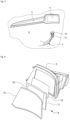
Fig. 4 est une vue en perspective éclatée du panneau d'affichage lumineux de la garniture de porte de lafigure 1 . - En référence à la
figure 1 , est représenté partiellement l'habitacle 100 d'un véhicule automobile 110. L'habitacle 100 comprend deux sièges avant 1 et des sièges passagers arrière 2. Sur lafigure 1 , est représentée la portière arrière gauche 3 permettant l'entrée et la sortie des passagers arrière. La portière arrière gauche 3 est munie d'une garniture 4 de porte selon l'invention. Comme il apparaît de cette figure, la garniture 4 de porte est configurée pour habiller la partie interne de la portière 3. - Dans la description qui suit, une garniture de porte selon l'invention est décrite pour une portière gauche. Cette description est également valable pour une garniture de porte d'une portière droite.
- La garniture 4 de porte comprend une façade externe 5, par exemple obtenue par moulage injection de matière plastique, dans laquelle est intégré un panneau d'affichage lumineux 6. La garniture 4 de porte comprend également une poignée 7 configurée pour pouvoir être prise en main par un passager installé à l'arrière du véhicule. La poignée 7 (voir aussi
Figure 3 ) comprend un bouton 14 permettant l'ouverture de la portière 3. - En référence aux
figures 1 et 2 , le panneau d'affichage lumineux 6 est relié, par exemple de manière filaire, à une caméra 8 située à l'emplacement du rétroviseur extérieur latéral gauche 9 du véhicule 110. Comme il apparaît de lafigure 2 , la caméra 8 est orientée afin de prendre une image de l'environnement latéral arrière gauche du véhicule 110. Le panneau d'affichage lumineux 6 est configuré pour afficher l'image captée par la caméra 8. - La caméra 8 du véhicule 110 permet d'afficher sur le panneau d'affichage lumineux 6 une image du trafic routier latéral et arrière dont est exclu tout angle mort. La caméra 8 permet également de restituer sur le panneau d'affichage lumineux 6 une image nette, même en temps de pluie ou de brouillard.
- En référence aux
figures 1 ,3 et 4 , le panneau d'affichage 6 comprend un support d'affichage flexible 10. Le support d'affichage flexible 10 peut par exemple être une dalle électronique de forme tridimensionnelle courbe. La dalle électronique formant le support d'affichage flexible 10 peut par exemple être une plaque conformable constituée de plastique uniquement. La plaque peut être apte à être courbée selon un rayon de courbure allant jusqu'à 80 mm. La plaque peut par exemple présenter une épaisseur d'environ 130 µm. Une telle plaque peut aisément être réalisée par injection de matière plastique pour permettre des formes variées et/ou pour être munie d'évidements traversant. Le support d'affichage flexible 10 permet de transmettre des informations lumineuses à l'attention du passager arrière au moyen d'un affichage de type OLCD (Organic Liquid Crystal Display). - Le support d'affichage flexible 10 est équipé d'une unité de commande électronique (ECU) 11. L'unité de commande électronique 11 réalise un traitement de l'image envoyée par la caméra 8 (voir
figure 2 ) au support d'affichage flexible 10. En fonction des signaux électroniques reçus, par exemple de la caméra 8, le support d'affichage flexible 10 délivrera un message lumineux spécifique qui sera visible par le passager arrière depuis l'habitacle 100 du véhicule 110 (voirfigure 1 ). En particulier, le message lumineux qui s'affichera renseignera le passager arrière sur l'état du trafic routier latéral gauche et arrière et sur l'état de l'environnement extérieur immédiat du véhicule. - Le support d'affichage flexible 10 est muni sur sa face externe d'un écran de protection 12. L'écran de protection 12 est transparent ou translucide et il possède également une forme tridimensionnelle courbe complémentaire de celle du support d'affichage flexible 10.
- L'écran de protection 12 permet d'éviter une détérioration prématurée du support d'affichage flexible 10. Un tel écran de protection 12 peut par exemple être réalisé en verre ou en matière plastique injectée, notamment en poly-méthacrylate de méthyle (PMMA) ou en polycarbonate (PC).
- L'écran de protection 12 peut être fixé au support d'affichage flexible 10 au moyen d'une couche adhésive transparente, par exemple un film de colle optique transparente, de type OCA (Optically Clear Adhesive), par exemple par lamination.
- La face externe de l'écran de protection 12 peut présenter une finition anti-reflet et/ou anti-trace de doigts. Une telle finition permet un confort d'utilisation du panneau d'affichage lumineux 6 pour l'utilisateur.
- La face externe de l'écran de protection 12 peut être recouverte d'une couche sensible au toucher (par exemple capacitive, résistive ou piézo-électrique). Une telle couche sensible au toucher présente sur l'écran de protection 12 confère à l'image affichée une clarté optimale ainsi qu'un confort d'utilisation du panneau d'affichage 6 pour l'utilisateur. En effet, grâce à la présence de la couche sensible au toucher, l'écran 12 forme une interface interactive. Le passager arrière peut ainsi par exemple réaliser un zoom de l'image en simplement touchant l'écran 12 avec son doigt à l'endroit désiré.
- En référence à la
figure 4 , le support d'affichage flexible 10 est muni sur sa face interne d'un panneau diffuseur de lumière 13. Le panneau diffuseur de lumière 13 est configuré pour rétroéclairer la face externe du support d'affichage flexible 10. Ainsi, le panneau diffuseur de lumière 13 peut comprendre une source lumineuse, par exemple une LED, et un panneau réflecteur pour renvoyer la lumière de la source lumineuse vers la face externe du support d'affichage flexible 10. Un tel rétroéclairage du support d'affichage permet un confort d'utilisation amélioré, en particulier lors d'une circulation de nuit. - En référence à la
figure 3 , la poignée 7 comprend un pavé tactile 15 configuré pour pointer des éléments sur l'image affichée par le panneau d'affichage lumineux 6. Sur l'exemple représenté, le pavé tactile 15 est situé à proximité du bouton 14 permettant l'ouverture de la portière 3. - Ainsi, l'utilisation du panneau d'affichage lumineux est particulièrement intuitive. Lorsque le véhicule 110 est à l'arrêt et que le passager arrière souhaite sortir du véhicule par la portière arrière gauche 3, il peut saisir la poignée 7 avec sa main gauche, de sorte que son pouce se trouve en regard du pavé tactile 15. Il peut alors aisément manipuler le pavé tactile 15 avec son pouce afin de consulter l'information qu'il souhaite recevoir sur l'état de la circulation sur le côté gauche et arrière du véhicule sur le panneau d'affichage lumineux 6. Si nécessaire, il peut ainsi mouvoir son pouce sur le pavé tactile 15 afin de faire un zoom sur un endroit particulier de l'image affichée sur le panneau d'affichage lumineux ou pour décaler cette image.
- Lorsque le passager est assuré qu'aucun obstacle ne risque d'entraver l'ouverture de la portière 3, il peut alors tout naturellement actionner le bouton 14 d'ouverture de la portière 3 en toute confiance.
- Le panneau d'affichage 6 et éventuellement le pavé tactile 15 peuvent également être utilisés pour transmettre toute autre sorte d'informations au(x) passager(s) arrière, telles que des informations relatives à l'habitacle du véhicule, température, qualité de l'air, ou des informations multimedia, telles que des chaînes de radio, de télévision, des jeux, interactif sou non, etc...
- La garniture de porte selon l'invention permet à un passager arrière de procéder à l'ouverture de la portière en toute sécurité, sans risque de causer un dommage à un véhicule ou tout autre moyen de transport mobile circulant à proximité du véhicule. La garniture de porte selon l'invention permet en outre de fournir une interface utilisateur dédiée pour un passager arrière d'un véhicule, agréable et pratique à utiliser, facile à prendre en main et ergonomique tout en respectant le design de l'habitacle.
Claims (12)
- Garniture (4) de porte d'un véhicule automobile (110) configurée pour habiller une portière (3) située sur un côté dudit véhicule, ladite garniture (4) de porte étant caractérisée en ce qu'elle comprend un panneau d'affichage lumineux (6) relié à une caméra (8) située à l'emplacement du rétroviseur extérieur latéral du véhicule (110) situé sur le même côté du véhicule que ladite portière, ledit panneau d'affichage lumineux (6) étant apte à afficher l'image captée par ladite caméra (8), et en ce qu'elle comprend en outre un pavé tactile (15) distinct dudit panneau d'affichage lumineux (6), ledit pavé tactile (15) étant configuré pour pointer des éléments sur l'image affichée par ledit panneau d'affichage lumineux (6).
- Garniture (4) de porte selon la revendication 1, caractérisée en ce que ledit panneau d'affichage lumineux (6) comprend un support d'affichage flexible (10).
- Garniture (4) de porte selon la revendication 2, caractérisée en ce que ledit panneau d'affichage lumineux (6) est intégré dans un support de façade (5) formant au moins une partie de ladite garniture (4).
- Garniture (4) de porte selon l'une des revendications 2 à 3, caractérisée en ce que ledit support d'affichage flexible (10) est une dalle électronique possédant une forme tridimensionnelle courbe.
- Garniture (4) de porte selon la revendication 4, caractérisée en ce que ledit support d'affichage flexible (10) est muni sur sa face externe d'un écran de protection (12) transparent ou translucide possédant une forme tridimensionnelle courbe.
- Garniture (4) de porte selon la revendication 5, caractérisée en ce que ledit écran de protection (12) est fixé sur la face externe dudit support d'affichage flexible (10) au moyen d'une couche adhésive transparente.
- Garniture (4) de porte selon la revendication 5 ou 6, caractérisée en ce que la face externe dudit écran de protection (12) présente une finition anti-reflet et/ou anti-trace de doigts.
- Garniture (4) de porte selon l'une quelconque des revendications 5 à 7, caractérisée en ce que la face externe de l'écran de protection (12) est recouverte d'une couche sensible au toucher.
- Garniture (4) de porte selon l'une quelconque des revendications 2 à 8, caractérisée en ce que le support d'affichage flexible (10) est équipé d'une unité de commande électronique (11) réalisant un traitement de l'image envoyée par la caméra (8).
- Garniture (4) de porte selon l'une quelconque des revendications 3 à 9, caractérisée en ce que le support d'affichage flexible (10) est muni sur sa face interne d'un panneau diffuseur de lumière (13) configuré pour rétroéclairer la face externe dudit support d'affichage flexible (10).
- Garniture (4) de porte selon l'une quelconque des revendications 1 à 10, caractérisée en ce que ledit pavé tactile (15) est situé sur une poignée (14) configurée pour autoriser l'ouverture et la fermeture de ladite portière (3).
- Véhicule automobile (110) comprenant au moins une portière (3) équipée d'une garniture (4) de porte selon l'une quelconque des revendications 1 à 11.
Applications Claiming Priority (2)
| Application Number | Priority Date | Filing Date | Title |
|---|---|---|---|
| FR1906785A FR3097490B1 (fr) | 2019-06-24 | 2019-06-24 | Garniture de portière latérale d'un véhicule automobile |
| PCT/FR2020/050984 WO2020260789A1 (fr) | 2019-06-24 | 2020-06-10 | Garniture de portière latérale d'un véhicule automobile |
Publications (2)
| Publication Number | Publication Date |
|---|---|
| EP3986752A1 EP3986752A1 (fr) | 2022-04-27 |
| EP3986752B1 true EP3986752B1 (fr) | 2023-07-05 |
Family
ID=68343039
Family Applications (1)
| Application Number | Title | Priority Date | Filing Date |
|---|---|---|---|
| EP20743200.6A Active EP3986752B1 (fr) | 2019-06-24 | 2020-06-10 | Garniture de portière latérale d'un véhicule automobile |
Country Status (4)
| Country | Link |
|---|---|
| EP (1) | EP3986752B1 (fr) |
| ES (1) | ES2958986T3 (fr) |
| FR (1) | FR3097490B1 (fr) |
| WO (1) | WO2020260789A1 (fr) |
Families Citing this family (1)
| Publication number | Priority date | Publication date | Assignee | Title |
|---|---|---|---|---|
| FR3118734B1 (fr) * | 2021-01-13 | 2024-04-05 | Faurecia Interieur Ind | Véhicule automobile équipé d’un dispositif de visualisation électronique |
Family Cites Families (3)
| Publication number | Priority date | Publication date | Assignee | Title |
|---|---|---|---|---|
| JP5013184B2 (ja) * | 2007-06-28 | 2012-08-29 | アイシン・エィ・ダブリュ株式会社 | 運転支援装置及びコンピュータプログラム |
| DE102016011307B4 (de) * | 2016-09-19 | 2024-02-15 | Audi Ag | Kraftfahrzeug |
| JP6585571B2 (ja) * | 2016-09-21 | 2019-10-02 | 矢崎総業株式会社 | 表示装置、及び、車両用ドア |
-
2019
- 2019-06-24 FR FR1906785A patent/FR3097490B1/fr not_active Expired - Fee Related
-
2020
- 2020-06-10 WO PCT/FR2020/050984 patent/WO2020260789A1/fr not_active Ceased
- 2020-06-10 EP EP20743200.6A patent/EP3986752B1/fr active Active
- 2020-06-10 ES ES20743200T patent/ES2958986T3/es active Active
Also Published As
| Publication number | Publication date |
|---|---|
| FR3097490B1 (fr) | 2023-11-24 |
| FR3097490A1 (fr) | 2020-12-25 |
| EP3986752A1 (fr) | 2022-04-27 |
| WO2020260789A1 (fr) | 2020-12-30 |
| ES2958986T3 (es) | 2024-02-19 |
Similar Documents
| Publication | Publication Date | Title |
|---|---|---|
| US6916099B2 (en) | Rearview/display mirror assembly | |
| CN101535087B (zh) | 具有显示装置的内部后视镜 | |
| EP3230790B1 (fr) | Afficheur tête haute pour véhicule automobile | |
| EP2773524B1 (fr) | Module de commande et d'affichage pour véhicule automobile | |
| JPWO2019181944A1 (ja) | 車両用リアモジュールの製造方法、車両用バックドア、車両用リアモジュールおよび車両用モジュール | |
| WO2012131188A1 (fr) | Module de commande et d'affichage pour vehicule automobile | |
| FR2911555A1 (fr) | Amenagement interieur de vehicule automobile. | |
| FR3048208A1 (fr) | Ensemble d'habillage de vehicule comprenant un compartiment de rangement et un rideau | |
| EP3986752B1 (fr) | Garniture de portière latérale d'un véhicule automobile | |
| EP2637887B1 (fr) | Module de commande et d'affichage pour vehicule automobile et procede de fabrication correspondant | |
| EP4499433B1 (fr) | Dispositif d'affichage projeté pour planche de bord de véhicule automobile | |
| JP4999626B2 (ja) | 表示装置付き後写鏡装置 | |
| EP3986740A1 (fr) | Tableau de bord d'un véhicule automobile | |
| FR3059817A1 (fr) | Module d'affichage du type lcd pour un habitacle de vehicule et habitacle de vehicule comprenant un tel module | |
| EP3795406B1 (fr) | Pièce de véhicule avec interface utilisateur | |
| FR3083182A1 (fr) | Module lumineux pour l'eclairage de l'habitacle d'un vehicule automobile comprenant une interface tactile | |
| FR3060783A1 (fr) | Dispositif de commande tactile, vehicule equipe d'un tel dispositif, procede de fabrication correspondant | |
| EP4440883B1 (fr) | Procede de fabrication d'un vitrage comprenant une embase destinee a un systeme d'assistance a la conduite d'un vehicule automobile, embase et vitrage | |
| FR3155177A1 (fr) | Système de visualisation de véhicule comprenant un dispositif d’affichage intégré | |
| FR3056776A1 (fr) | Dispositif d'affichage pour vehicule automobile et procede de fabrication | |
| KR20250119639A (ko) | 차량의 차량 창문, 차량 창문을 제조하는 방법, 및 이러한 차량 창문을 갖는 차량 | |
| FR3152763A1 (fr) | Elément de garnissage comprenant une lame semi-réfléchissante pour réfléchir la lumière d’une unité de génération d’image | |
| FR3164799A1 (fr) | Système d’affichage d’images étendu et véhicule comportant le système d’affichage d’images étendu | |
| FR3091673A1 (fr) | Module de pare brise de véhicule | |
| FR3083629A1 (fr) | Module d'affichage du type a interface tactile pour un habitacle de vehicule et habitacle comprenant une telle interface |
Legal Events
| Date | Code | Title | Description |
|---|---|---|---|
| STAA | Information on the status of an ep patent application or granted ep patent |
Free format text: STATUS: UNKNOWN |
|
| STAA | Information on the status of an ep patent application or granted ep patent |
Free format text: STATUS: THE INTERNATIONAL PUBLICATION HAS BEEN MADE |
|
| PUAI | Public reference made under article 153(3) epc to a published international application that has entered the european phase |
Free format text: ORIGINAL CODE: 0009012 |
|
| STAA | Information on the status of an ep patent application or granted ep patent |
Free format text: STATUS: REQUEST FOR EXAMINATION WAS MADE |
|
| 17P | Request for examination filed |
Effective date: 20220105 |
|
| AK | Designated contracting states |
Kind code of ref document: A1 Designated state(s): AL AT BE BG CH CY CZ DE DK EE ES FI FR GB GR HR HU IE IS IT LI LT LU LV MC MK MT NL NO PL PT RO RS SE SI SK SM TR |
|
| DAV | Request for validation of the european patent (deleted) | ||
| DAX | Request for extension of the european patent (deleted) | ||
| GRAP | Despatch of communication of intention to grant a patent |
Free format text: ORIGINAL CODE: EPIDOSNIGR1 |
|
| STAA | Information on the status of an ep patent application or granted ep patent |
Free format text: STATUS: GRANT OF PATENT IS INTENDED |
|
| INTG | Intention to grant announced |
Effective date: 20230103 |
|
| GRAS | Grant fee paid |
Free format text: ORIGINAL CODE: EPIDOSNIGR3 |
|
| GRAA | (expected) grant |
Free format text: ORIGINAL CODE: 0009210 |
|
| STAA | Information on the status of an ep patent application or granted ep patent |
Free format text: STATUS: THE PATENT HAS BEEN GRANTED |
|
| AK | Designated contracting states |
Kind code of ref document: B1 Designated state(s): AL AT BE BG CH CY CZ DE DK EE ES FI FR GB GR HR HU IE IS IT LI LT LU LV MC MK MT NL NO PL PT RO RS SE SI SK SM TR |
|
| REG | Reference to a national code |
Ref country code: CH Ref legal event code: EP |
|
| REG | Reference to a national code |
Ref country code: AT Ref legal event code: REF Ref document number: 1584575 Country of ref document: AT Kind code of ref document: T Effective date: 20230715 |
|
| REG | Reference to a national code |
Ref country code: DE Ref legal event code: R096 Ref document number: 602020013385 Country of ref document: DE |
|
| REG | Reference to a national code |
Ref country code: IE Ref legal event code: FG4D Free format text: LANGUAGE OF EP DOCUMENT: FRENCH |
|
| REG | Reference to a national code |
Ref country code: LT Ref legal event code: MG9D |
|
| RAP4 | Party data changed (patent owner data changed or rights of a patent transferred) |
Owner name: NOVARES FRANCE |
|
| REG | Reference to a national code |
Ref country code: NL Ref legal event code: MP Effective date: 20230705 |
|
| REG | Reference to a national code |
Ref country code: AT Ref legal event code: MK05 Ref document number: 1584575 Country of ref document: AT Kind code of ref document: T Effective date: 20230705 |
|
| PG25 | Lapsed in a contracting state [announced via postgrant information from national office to epo] |
Ref country code: NL Free format text: LAPSE BECAUSE OF FAILURE TO SUBMIT A TRANSLATION OF THE DESCRIPTION OR TO PAY THE FEE WITHIN THE PRESCRIBED TIME-LIMIT Effective date: 20230705 |
|
| PG25 | Lapsed in a contracting state [announced via postgrant information from national office to epo] |
Ref country code: GR Free format text: LAPSE BECAUSE OF FAILURE TO SUBMIT A TRANSLATION OF THE DESCRIPTION OR TO PAY THE FEE WITHIN THE PRESCRIBED TIME-LIMIT Effective date: 20231006 |
|
| PG25 | Lapsed in a contracting state [announced via postgrant information from national office to epo] |
Ref country code: IS Free format text: LAPSE BECAUSE OF FAILURE TO SUBMIT A TRANSLATION OF THE DESCRIPTION OR TO PAY THE FEE WITHIN THE PRESCRIBED TIME-LIMIT Effective date: 20231105 |
|
| PG25 | Lapsed in a contracting state [announced via postgrant information from national office to epo] |
Ref country code: SE Free format text: LAPSE BECAUSE OF FAILURE TO SUBMIT A TRANSLATION OF THE DESCRIPTION OR TO PAY THE FEE WITHIN THE PRESCRIBED TIME-LIMIT Effective date: 20230705 Ref country code: RS Free format text: LAPSE BECAUSE OF FAILURE TO SUBMIT A TRANSLATION OF THE DESCRIPTION OR TO PAY THE FEE WITHIN THE PRESCRIBED TIME-LIMIT Effective date: 20230705 Ref country code: PT Free format text: LAPSE BECAUSE OF FAILURE TO SUBMIT A TRANSLATION OF THE DESCRIPTION OR TO PAY THE FEE WITHIN THE PRESCRIBED TIME-LIMIT Effective date: 20231106 Ref country code: NO Free format text: LAPSE BECAUSE OF FAILURE TO SUBMIT A TRANSLATION OF THE DESCRIPTION OR TO PAY THE FEE WITHIN THE PRESCRIBED TIME-LIMIT Effective date: 20231005 Ref country code: LV Free format text: LAPSE BECAUSE OF FAILURE TO SUBMIT A TRANSLATION OF THE DESCRIPTION OR TO PAY THE FEE WITHIN THE PRESCRIBED TIME-LIMIT Effective date: 20230705 Ref country code: LT Free format text: LAPSE BECAUSE OF FAILURE TO SUBMIT A TRANSLATION OF THE DESCRIPTION OR TO PAY THE FEE WITHIN THE PRESCRIBED TIME-LIMIT Effective date: 20230705 Ref country code: IS Free format text: LAPSE BECAUSE OF FAILURE TO SUBMIT A TRANSLATION OF THE DESCRIPTION OR TO PAY THE FEE WITHIN THE PRESCRIBED TIME-LIMIT Effective date: 20231105 Ref country code: HR Free format text: LAPSE BECAUSE OF FAILURE TO SUBMIT A TRANSLATION OF THE DESCRIPTION OR TO PAY THE FEE WITHIN THE PRESCRIBED TIME-LIMIT Effective date: 20230705 Ref country code: GR Free format text: LAPSE BECAUSE OF FAILURE TO SUBMIT A TRANSLATION OF THE DESCRIPTION OR TO PAY THE FEE WITHIN THE PRESCRIBED TIME-LIMIT Effective date: 20231006 Ref country code: FI Free format text: LAPSE BECAUSE OF FAILURE TO SUBMIT A TRANSLATION OF THE DESCRIPTION OR TO PAY THE FEE WITHIN THE PRESCRIBED TIME-LIMIT Effective date: 20230705 Ref country code: AT Free format text: LAPSE BECAUSE OF FAILURE TO SUBMIT A TRANSLATION OF THE DESCRIPTION OR TO PAY THE FEE WITHIN THE PRESCRIBED TIME-LIMIT Effective date: 20230705 |
|
| REG | Reference to a national code |
Ref country code: ES Ref legal event code: FG2A Ref document number: 2958986 Country of ref document: ES Kind code of ref document: T3 Effective date: 20240219 |
|
| PG25 | Lapsed in a contracting state [announced via postgrant information from national office to epo] |
Ref country code: PL Free format text: LAPSE BECAUSE OF FAILURE TO SUBMIT A TRANSLATION OF THE DESCRIPTION OR TO PAY THE FEE WITHIN THE PRESCRIBED TIME-LIMIT Effective date: 20230705 |
|
| REG | Reference to a national code |
Ref country code: DE Ref legal event code: R097 Ref document number: 602020013385 Country of ref document: DE |
|
| PG25 | Lapsed in a contracting state [announced via postgrant information from national office to epo] |
Ref country code: SM Free format text: LAPSE BECAUSE OF FAILURE TO SUBMIT A TRANSLATION OF THE DESCRIPTION OR TO PAY THE FEE WITHIN THE PRESCRIBED TIME-LIMIT Effective date: 20230705 Ref country code: RO Free format text: LAPSE BECAUSE OF FAILURE TO SUBMIT A TRANSLATION OF THE DESCRIPTION OR TO PAY THE FEE WITHIN THE PRESCRIBED TIME-LIMIT Effective date: 20230705 Ref country code: EE Free format text: LAPSE BECAUSE OF FAILURE TO SUBMIT A TRANSLATION OF THE DESCRIPTION OR TO PAY THE FEE WITHIN THE PRESCRIBED TIME-LIMIT Effective date: 20230705 Ref country code: DK Free format text: LAPSE BECAUSE OF FAILURE TO SUBMIT A TRANSLATION OF THE DESCRIPTION OR TO PAY THE FEE WITHIN THE PRESCRIBED TIME-LIMIT Effective date: 20230705 Ref country code: CZ Free format text: LAPSE BECAUSE OF FAILURE TO SUBMIT A TRANSLATION OF THE DESCRIPTION OR TO PAY THE FEE WITHIN THE PRESCRIBED TIME-LIMIT Effective date: 20230705 Ref country code: SK Free format text: LAPSE BECAUSE OF FAILURE TO SUBMIT A TRANSLATION OF THE DESCRIPTION OR TO PAY THE FEE WITHIN THE PRESCRIBED TIME-LIMIT Effective date: 20230705 |
|
| PLBE | No opposition filed within time limit |
Free format text: ORIGINAL CODE: 0009261 |
|
| STAA | Information on the status of an ep patent application or granted ep patent |
Free format text: STATUS: NO OPPOSITION FILED WITHIN TIME LIMIT |
|
| PG25 | Lapsed in a contracting state [announced via postgrant information from national office to epo] |
Ref country code: IT Free format text: LAPSE BECAUSE OF FAILURE TO SUBMIT A TRANSLATION OF THE DESCRIPTION OR TO PAY THE FEE WITHIN THE PRESCRIBED TIME-LIMIT Effective date: 20230705 |
|
| 26N | No opposition filed |
Effective date: 20240408 |
|
| PG25 | Lapsed in a contracting state [announced via postgrant information from national office to epo] |
Ref country code: SI Free format text: LAPSE BECAUSE OF FAILURE TO SUBMIT A TRANSLATION OF THE DESCRIPTION OR TO PAY THE FEE WITHIN THE PRESCRIBED TIME-LIMIT Effective date: 20230705 |
|
| PG25 | Lapsed in a contracting state [announced via postgrant information from national office to epo] |
Ref country code: BG Free format text: LAPSE BECAUSE OF FAILURE TO SUBMIT A TRANSLATION OF THE DESCRIPTION OR TO PAY THE FEE WITHIN THE PRESCRIBED TIME-LIMIT Effective date: 20230705 |
|
| PG25 | Lapsed in a contracting state [announced via postgrant information from national office to epo] |
Ref country code: BG Free format text: LAPSE BECAUSE OF FAILURE TO SUBMIT A TRANSLATION OF THE DESCRIPTION OR TO PAY THE FEE WITHIN THE PRESCRIBED TIME-LIMIT Effective date: 20230705 |
|
| REG | Reference to a national code |
Ref country code: DE Ref legal event code: R119 Ref document number: 602020013385 Country of ref document: DE |
|
| PG25 | Lapsed in a contracting state [announced via postgrant information from national office to epo] |
Ref country code: MC Free format text: LAPSE BECAUSE OF FAILURE TO SUBMIT A TRANSLATION OF THE DESCRIPTION OR TO PAY THE FEE WITHIN THE PRESCRIBED TIME-LIMIT Effective date: 20230705 |
|
| REG | Reference to a national code |
Ref country code: CH Ref legal event code: PL |
|
| PG25 | Lapsed in a contracting state [announced via postgrant information from national office to epo] |
Ref country code: LU Free format text: LAPSE BECAUSE OF NON-PAYMENT OF DUE FEES Effective date: 20240610 |
|
| GBPC | Gb: european patent ceased through non-payment of renewal fee |
Effective date: 20240610 |
|
| PG25 | Lapsed in a contracting state [announced via postgrant information from national office to epo] |
Ref country code: DE Free format text: LAPSE BECAUSE OF NON-PAYMENT OF DUE FEES Effective date: 20250101 |
|
| PG25 | Lapsed in a contracting state [announced via postgrant information from national office to epo] |
Ref country code: IE Free format text: LAPSE BECAUSE OF NON-PAYMENT OF DUE FEES Effective date: 20240610 |
|
| PG25 | Lapsed in a contracting state [announced via postgrant information from national office to epo] |
Ref country code: BE Free format text: LAPSE BECAUSE OF NON-PAYMENT OF DUE FEES Effective date: 20240630 Ref country code: CH Free format text: LAPSE BECAUSE OF NON-PAYMENT OF DUE FEES Effective date: 20240630 |
|
| PG25 | Lapsed in a contracting state [announced via postgrant information from national office to epo] |
Ref country code: GB Free format text: LAPSE BECAUSE OF NON-PAYMENT OF DUE FEES Effective date: 20240610 |
|
| REG | Reference to a national code |
Ref country code: BE Ref legal event code: MM Effective date: 20240630 |
|
| PGFP | Annual fee paid to national office [announced via postgrant information from national office to epo] |
Ref country code: FR Payment date: 20250618 Year of fee payment: 6 |
|
| REG | Reference to a national code |
Ref country code: ES Ref legal event code: FD2A Effective date: 20250728 |
|
| PG25 | Lapsed in a contracting state [announced via postgrant information from national office to epo] |
Ref country code: ES Free format text: LAPSE BECAUSE OF NON-PAYMENT OF DUE FEES Effective date: 20240611 |
|
| PG25 | Lapsed in a contracting state [announced via postgrant information from national office to epo] |
Ref country code: CY Free format text: LAPSE BECAUSE OF FAILURE TO SUBMIT A TRANSLATION OF THE DESCRIPTION OR TO PAY THE FEE WITHIN THE PRESCRIBED TIME-LIMIT; INVALID AB INITIO Effective date: 20200610 |
|
| PG25 | Lapsed in a contracting state [announced via postgrant information from national office to epo] |
Ref country code: HU Free format text: LAPSE BECAUSE OF FAILURE TO SUBMIT A TRANSLATION OF THE DESCRIPTION OR TO PAY THE FEE WITHIN THE PRESCRIBED TIME-LIMIT; INVALID AB INITIO Effective date: 20200610 |