EP3986624B1 - Guss- und wellenanordnung für ein scheibensieb - Google Patents
Guss- und wellenanordnung für ein scheibensieb Download PDFInfo
- Publication number
- EP3986624B1 EP3986624B1 EP20826552.0A EP20826552A EP3986624B1 EP 3986624 B1 EP3986624 B1 EP 3986624B1 EP 20826552 A EP20826552 A EP 20826552A EP 3986624 B1 EP3986624 B1 EP 3986624B1
- Authority
- EP
- European Patent Office
- Prior art keywords
- cast
- screening element
- shaft
- casts
- sleeve
- Prior art date
- Legal status (The legal status is an assumption and is not a legal conclusion. Google has not performed a legal analysis and makes no representation as to the accuracy of the status listed.)
- Active
Links
Images


Classifications
-
- B—PERFORMING OPERATIONS; TRANSPORTING
- B07—SEPARATING SOLIDS FROM SOLIDS; SORTING
- B07B—SEPARATING SOLIDS FROM SOLIDS BY SIEVING, SCREENING, SIFTING OR BY USING GAS CURRENTS; SEPARATING BY OTHER DRY METHODS APPLICABLE TO BULK MATERIAL, e.g. LOOSE ARTICLES FIT TO BE HANDLED LIKE BULK MATERIAL
- B07B1/00—Sieving, screening, sifting, or sorting solid materials using networks, gratings, grids, or the like
- B07B1/12—Apparatus having only parallel elements
- B07B1/14—Roller screens
- B07B1/15—Roller screens using corrugated, grooved or ribbed rollers
-
- B—PERFORMING OPERATIONS; TRANSPORTING
- B07—SEPARATING SOLIDS FROM SOLIDS; SORTING
- B07B—SEPARATING SOLIDS FROM SOLIDS BY SIEVING, SCREENING, SIFTING OR BY USING GAS CURRENTS; SEPARATING BY OTHER DRY METHODS APPLICABLE TO BULK MATERIAL, e.g. LOOSE ARTICLES FIT TO BE HANDLED LIKE BULK MATERIAL
- B07B1/00—Sieving, screening, sifting, or sorting solid materials using networks, gratings, grids, or the like
- B07B1/12—Apparatus having only parallel elements
- B07B1/14—Roller screens
- B07B1/145—Roller screens the material to be screened moving along the axis of the parallel elements
-
- B—PERFORMING OPERATIONS; TRANSPORTING
- B07—SEPARATING SOLIDS FROM SOLIDS; SORTING
- B07B—SEPARATING SOLIDS FROM SOLIDS BY SIEVING, SCREENING, SIFTING OR BY USING GAS CURRENTS; SEPARATING BY OTHER DRY METHODS APPLICABLE TO BULK MATERIAL, e.g. LOOSE ARTICLES FIT TO BE HANDLED LIKE BULK MATERIAL
- B07B1/00—Sieving, screening, sifting, or sorting solid materials using networks, gratings, grids, or the like
- B07B1/12—Apparatus having only parallel elements
- B07B1/14—Roller screens
- B07B1/15—Roller screens using corrugated, grooved or ribbed rollers
- B07B1/155—Roller screens using corrugated, grooved or ribbed rollers the rollers having a star shaped cross section
Definitions
- the invention relates to a cast and adjacent casts on a shaft for providing a shaft assembly for a disc screen.
- a mechanical screen for separating materials, more precisely its disc screen, i.e. the screening surface, is provided with adjacent rotating shaft assemblies arranged one after another in the longitudinal direction of the machine.
- the disc screen comprises adjacent shaft assemblies provided with screening elements.
- the screening elements may have various shapes, such as discs or stars, or their shape may be irregular and/or comprise protruding parts.
- the screening elements of adjacent shaft assemblies are interlocked, whereby screening slots are left between them.
- Pieces having a particle size larger than the screening slots remain on the disc screen, and the rotating screening elements convey the pieces to, for example, a conveyor downstream of the disc screen.
- Pieces having a particle size smaller than the screening slots fall through the screening slots of the disc screen e.g. into a funnel or onto a conveyor under the disc screen.
- the screening elements comprise an opening, typically in the center of the element, to enable their arrangement on a shaft so that the shaft extends through the opening.
- the profile of the shaft may be, for example, circular or angular.
- Sleeves may be provided between the screening elements on the shaft to keep the screening elements at a given space from each other on the shaft.
- the document FR-A1-2938157 discloses a cast in accordance with the preamble of claim 1 and a shaft assembly in accordance with the preamble of claim 10.
- the aim is to implement a screening element and a sleeve suitable for a shaft assembly of a disc screen.
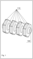
- FIG. 1 shows a shaft assembly according to one embodiment of the invention.
- screening elements 110 are provided on a shaft 100.
- the screening elements 110 of Fig. 1 are hexagonal discs.
- the screening elements may have different shapes, such as discs or stars, or the shape may be irregular and/or comprise protruding parts.
- Sleeves are provided between the screening elements 110 .
- a sleeve is a hollow, i.e. tubular or annular, part placed around the shaft 100 and extending in parallel with the shaft 100.
- the sleeve defines the axial spacing between two screening elements.
- an auxiliary sleeve may be placed between the sleeve parts on the shaft 100.
- Both the screening elements 110 and the sleeves may comprise two abutting casts which may be cast components or pieces. This is illustrated in more detail in Fig. 2 .
- FIG. 2 shows a shaft assembly according to one embodiment of the invention.
- the screening elements 210 and the sleeves 220 between them on the shaft 200 comprise casts 230.
- a cast 230 may be a single uniform cast piece.
- the cast 230 comprises a screening element part 232 and a sleeve part 231.
- One end of the sleeve part 231 of the cast is joined to the screening element part 232 forming a single piece with the sleeve part 231, and the other end is an exposed, unattached outer edge.
- a screening element 210 on the shaft 200 comprises abutting screening element parts 232-1 , 232-2 of two casts 230.
- the screening element part 232-1 of one cast is placed against the screening element part 232-2 of an adjacent cast on the shaft 200.
- the abutting screening element parts 232-1 , 232-2 of the two adjacent casts constitute the screening element 210.
- a sleeve 220 between screening elements 210 on the shaft 200 comprises the abutting sleeve elements 231-1 , 231-2 of two casts 230.
- the sleeve part 231-1 of one cast is placed against the sleeve part 231-2 of an adjacent cast on the shaft 200.
- the abutting sleeve parts 231-1 , 231-2 constitute the sleeve 220 between the screening element parts.
- the casts may comprise or consist of a metal, a polymer, a plastic, or a composite.
- the metal may be, for example, aluminium, a light metal alloy, cast iron, or cast steel.
- the plastic may be, for example, a wear and weather resistant plastic, such as polyethylene (PE), for example high density polyethylene (HDPE), ultra high molecular weight polyethylene (UHMWPE).
- PE polyethylene
- HDPE high density polyethylene
- UHMWPE ultra high molecular weight polyethylene
- the composite may contain a wear resistant material, metal, ceramic, plastic, or a combination of these, such as a two or more component plastic/metal, metal-ceramic, or ceramic-plastic.
- the cast may be coated in part or in whole.
- the coating may comprise a composite or, for example, a substance comprising one or more metals, either in a mixture or in layers.
- the coating may protect from wear, smooth out the surface, and/or lubricate the surface.
- the casts can be made by forging, casting, or precision casting.
- the cast and/or its manufacturing method make it possible to define the structure and the components in an appropriate way, for example according to the use.
- the material strength of the cast and its components can be selected and adjusted to be appropriate.
- an appropriate material strength can be achieved in the different parts of the screening element to be formed of casts.
- Casts have no welded joints which could constitute a structurally weak point or a point of discontinuity during the use.
- the cast and/or its manufacturing method enable shaping, such as rounding, at specific selected points. By the shaping, advantages may be provided in the structure and in functionality during the use.
- the selection of materials suitable for manufacturing the cast is larger than that for a welded piece.
- aluminium and plastic are suitable for casting.
- the diameter of the outer surface of the sleeve part 231 may be substantially constant throughout the length of the sleeve part.
- the diameter of the outer surface of the sleeve part 231 may be narrower at the outer rim than at its end joining the screening element.
- the diameter of the outer surface of the sleeve part 231 may become steadily narrower towards its outer rim.
- the outer rim of the sleeve part 231 may constitute its narrowest part.
- the sleeve part 231-1 can be placed against the sleeve part 231-2 of the adjacent cast, or against an auxiliary sleeve to be placed between them, so that the outer rim of the sleeve part 231-1 abuts the outer rim of the adjacent sleeve part 231-2 or the auxiliary sleeve.
- the sleeve parts, or at least their outer rims, are substantially equal in size and shape, whereby they can be placed on the shaft so that their outer rims are abutting.
- the screening element part 232 comprises a disc-like part 233 and an outer fringe 234.
- the disc-like part or disc part 233 extends from the sleeve part 231 in a substantially transverse direction.
- the disc part 233 is a disc part substantially transverse to the longitudinal mantle of the sleeve part, and thereby to the shaft 200.
- the disc part 233 may constitute a flange for the cylindrical sleeve part 231.
- the outer edge of the disc part 233 may constitute a straight or angular circumference, for example a circular, hexagonal or octagonal circumference.
- the outer fringe 234 of the screening element part extends from the outer edge of the disc part 233 in a substantially transverse direction, substantially in parallel with the sleeve part 231 , and in a direction opposite to the sleeve part 231.
- a substantially transverse outer fringe 234 extends from the outer edge of the disc part, and a substantially transverse sleeve part 232 extends from the rim of the opening (shaft opening) in the disc part 233.
- the outer fringe 234 and the sleeve part 231 are substantially parallel and extend in opposite directions from the disc part 233.
- the integrated single-piece cast with a screening element part and a sleeve part makes it possible to compose the shaft assembly and the disc screen by using parts of one type only. Furthermore, the cast can be manufactured in one type only.
- the casts may be mirror symmetric.
- the cast may be mirror symmetric with respect to its rotation axis or with respect to an abutting cast of identical type.
- the casts may be mirror symmetric in their appearance and/or irrespective of the counterparts provided in them for engaging the two casts with each other.
- the casts are placed against each other in such a way on the shaft that the mating outer edges of the casts, the outer rims of the sleeve parts. In accordance with the invention, the outer fringes of the screening element parts are placed against each other.
- a screening element formed of two abutting screening element parts is hollow.
- the screening element parts may be abutting on their whole edge part limited by the outer circumference, in which case the screening element is not hollow.
- a hollow structure reduces the demand for material. With a hollow screening element, it is possible to achieve appropriate strength, hardness and/or wear strength suitable for the use.
- the joint between the screening element part 232 and the sleeve part 231 may be rounded.
- a large rounding may be provided at the joint of the screening element part 232 and the sleeve part 231 , i . e . at the foot of the sleeve part which is against the disc part 233 of the screening element part.
- the rounding makes the angle between the disc part 233 and the sleeve part 231 shallower.
- the rounding increases the diameter of the outer surface of the sleeve part 231.
- the diameter of the outer surface of the sleeve part 231 may be the largest at its foot which is against the disc part 233.
- the diameter of the outer surface of the sleeve part 231 may be larger at its foot or increase towards the foot, for example to 1.1 to 3.5 fold, such as 1.5 fold, compared with the diameter of the outermost outer surface of the sleeve part 231.
- the outermost surface of the sleeve part 231 can be placed against the corresponding surface of the sleeve part of the adjacent screening element. The rounding may be gradual so that the diameter of the outer surface of the sleeve part 231 decreases steadily towards its outer edge.
- the sleeve part 231 may be conical, and its foot may be expanding so that it expands towards the wall of the disc part 233.
- An inclined junction surface may be provided between the wall of the substantially straight disc part 233 and the mantle of the substantially straight sleeve part 231.
- a sleeve according to the solution of prior art may comprise an inner sleeve which determines the spacing between the screening elements, a middle sleeve which constitutes a bearing and thereby a wearing part, and an outermost sleeve whose rotation is not dependent on the rotation of the inner sleeves or the shaft.
- the casts may be mirror symmetric and identical to each other.
- the shaft assemblies of the disc screen can be composed of casts of a single type. It will not be necessary to manufacture different pieces, such as different screening elements or sleeves, or to fit them to each other.
- the casts are arranged pairwise to abut each other so that the screening element parts of adjacent casts are against each other. These cast pieces placed pairwise are assembled next to each other on a shaft. In this way, the sleeve parts of adjacent cast pairs are placed against each other.
- the shaft assembly comprises parts which correspond to those of a conventional implementation where the screening elements and the sleeves are separate parts.
- the sleeve parts of adjacent casts may abut each other on the shaft.
- the screening element parts of adjacent casts may constitute counterparts to be mated. The counterparts are mated so that their mutual spacing is small or minimized.
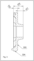
- FIG. 3 shows a cast according to one embodiment of the invention.
- the cast 330 is a cast single piece with a screening element part 332 and a sleeve part 33 1.
- the joint between the screening element part 332 and the sleeve part 331 is rounded so that there is no angle but the joint is a curved uniform surface.
- the screening element part 332 comprises a disc part 333 and an outer fringe 334.
- the disc part 333 is between the sleeve part 331 and the outer fringe 334.
- the outer fringe 334 can be placed against the outer fringe of another cast, a pair of casts.
- the casts can be placed against each other.
- Opposite casts may comprise mating parts or counterparts placed and to be placed against each other.
- Casts connected by the counterparts do not move with respect to each other, at least not as easily or as much as abutting casts without counterparts.
- the counterparts may facilitate the power transmission on the circumference, for example by keeping the casts together with respect to the rotation, also on the circumference.
- the casts can be placed and remain more tightly and less movably against each other. In this way it is possible to reduce wearing of the shafts and rattling of the casts or their deviation from their intended paths.
- the outer fringes 334 of two casts, to be placed against each other can constitute counterparts.
- the shape of the outer fringe 334 , or its side to be placed against the adjacent outer fringe, may be such that it takes its place, in the correct position, against the outer rim of the pair of casts.
- the mating counterparts may be placed on the outer fringe 334, in the disc part 333 , on their side or at their edge to be placed against the corresponding pair of casts.
- the counterparts may be provided in the sleeve parts of the casts, for example at the outermost rim of the sleeve part.
- the pair of casts can be placed in the correct position against each other.
- the casts of the pair do not substantially move against each other when they are placed in the correct position against each other. In this way, the casts can be arranged to rotate simultaneously and in a uniform manner around the shaft.
- the counterparts or mating parts can be formed by means of an interlocking or tongue-and-groove design, for example.
- a tongue-and-groove pair is shown in Fig. 3 , on the side of the outer fringe 334, which can be placed against the counterpart of the adjacent cast to form a screening element on the shaft.
- the counterpart may also be a pin or a protrusion, possibly shaped, and an opening or rim in the counterpart, possibly shaped in a corresponding way.
- the counterparts may be formed by grooves and elongated protrusions. Disc-like protrusions or V-shaped protrusions may also be placed against each other to form the counterparts.
- the screening element may have a symmetrical, for example hexagonal shape.
- the counterparts at the outer fringe of a symmetrical screening element part may comprise two types of counterparts which alternate, for example on the sides of a hexagon.
- the screening elements are symmetrical and can be placed against each other by means of the counterparts. Different counterparts are placed against each other. Their outer fringes abutting each other, the screening element parts constitute a hollow screening element. An empty space is left between the disc parts in the pair of casts. It is possible to implement the casts so that no empty space is left between the disc parts but it is filled with cast material as well.
- the counterparts may be placed, for example, in the disc part.
- the wall of the disc part facing another disc part may comprise, for example, protruding pins and/or hollow pins which can be placed against each other. Other shapes interlocking with or engaging each other are also possible.
- the placement of the counterparts in the disc part provides freedom for the shape of the screening element part, for example. Its appearance does not have to be fully symmetrical, but the screening element part may constitute an asymmetrical screening element comprising various protrusions, grooves or branches.
- Figure 4 shows a screening element according to one embodiment of the invention.
- the screening element comprises cast pieces 430 arranged pairwise.
- the cast piece 430 comprises a screening element part 432 and a sleeve part 431.
- the outer surface of the sleeve part 431 may be provided with a groove 435 extending in its longitudinal direction.
- the groove 435 may extend as a uniform groove onto the outer surface of the disc part of the screening element part 432.
- the groove 435 can be made during casting.
- the groove 435 can be worked afterwards.
- the groove 435 may function as a socalled break line. If material to be processed is twisted around the sleeve, the material can be cut by pressing with a blade at the break line. This facilitates and speeds up the cleaning and maintenance of the disc screen.
- the cast may comprise one or more grooves. For example, two grooves may be provided symmetrically with respect to the axis of rotation of the sleeve part.
- the cast can make it possible to use efficient manufacturing methods and to reduce the number of parts. Reducing the number of parts may simplify and/or accelerate the manufacture of the parts, the selection of the manufacturing method, the installation, and the assembly of the parts.
- the casts can make it possible to use a single manufacturing method and/or the manufacture of parts in one type only. By means of the cast and its manufacturing method, it is possible to utilize different materials. With the uniform cast, it is possible to prevent or reduce weaknesses causes by seams and joints.
- the cast and the shaft assembly can provide cost efficiency.
Landscapes
- Prostheses (AREA)
- Shafts, Cranks, Connecting Bars, And Related Bearings (AREA)
- Combined Means For Separation Of Solids (AREA)
- Holding Or Fastening Of Disk On Rotational Shaft (AREA)
Claims (11)
- Eine Gussform (230), die auf einer Welle (200) für ein Scheibensieb platziert werden kann, wobei die Gussform (230) einen Siebelementteil (232) und einen integralen Hülsenteil (231) umfasst, wobei der Siebelementteil (232) einen scheibenartigen Teil um die Welle (200) herum bildet und so konfiguriert ist, dass aneinanderstoßende Siebelementteile (232-1, 232-2) von zwei benachbarten Gussformen (230) ein Siebelement (210) bilden, und wobei der Hülsenteil (231) so konfiguriert ist, dass er einen axialen Abstand zwischen zwei benachbarten Siebelementen (210) definiert, und die Gussform (230) ferner eine Öffnung für die Welle (200) umfasst, dadurch gekennzeichnet, dass die Gussform so konfiguriert ist, dass nur äußere Ränder der Siebelementteile (232-1, 232-2) zweier benachbarter Gussformen (230) aneinander stoßen, so dass das gebildete Siebelement hohl ist und ein leerer Raum innerhalb des Siebelement (210) zwischen den äußeren Rändern verbleibt, die aneinander anliegen, wenn die zwei benachbarten Gussformen (230) auf der Welle (200) platziert werden.
- Die Gussform (230) nach Anspruch 1, wobei die Gussform (230) spiegelsymmetrisch in Bezug auf ihre Drehachse oder in Bezug auf ihre Oberfläche ist, die einer anderen Gussform (230) zugewandt ist, die auf die Welle (200) gesetzt werden soll.
- Die Gussform (230) nach einem der vorhergehenden Ansprüche, wobei die äußere Oberfläche des Hülsenteils (231) zylindrisch oder konisch ist, wobei der Durchmesser der äußeren Oberfläche des Hülsenteils (231) vom äußeren Rand des Hülsenteils bis zu seinem Fuß um das 1,1- bis 3,5-fache zunimmt, wobei der Fuß an dem Siebelementteil (232) liegt.
- Die Gussform (230) nach einem der vorhergehenden Ansprüche, wobei das Siebelement (232) die Welle (200) als scheibenförmiges Teil umgibt, dessen äußerer Rand ein gerader Kreis, ein Winkelkreis, ein Kreisumfang, ein Sechseck, ein Achteck ist oder regelmäßige oder unregelmäßige Vorsprünge oder Verzweigungen aufweist.
- Die Gussform (230) nach einem der vorhergehenden Ansprüche umfasst eines oder mehrere der folgenden Elemente: Metall, Kunststoff und Verbundwerkstoff; oder ist aus einem Metall, einem Kunststoff oder einem Verbundwerkstoff hergestellt.
- Die Gussform (230) nach einem der vorhergehenden Ansprüche, wobei das Siebelementteil (232) ein scheibenartiges Element umfasst, das sich in einer Querrichtung von dem Hülsenteil (231) aus erstreckt, sowie einen äußeren Rand, der sich in einer Querrichtung von dem scheibenartigen Teil im Wesentlichen parallel zu dem Hülsenteil (231) in einer dem Hülsenteil (231) entgegengesetzten Richtung erstreckt.
- Die Gussform (230) nach einem der vorhergehenden Ansprüche, die mit Hilfe von Gegenstücken gegen eine benachbarte Gussform (230) auf der Welle (200) platzierbar ist.
- Die Gussform (230) nach einem der vorhergehenden Ansprüche, wobei die Außenfläche des Hülsenteils (231) mit einer Nut versehen ist, die sich in Längsrichtung des Hülsenteils erstreckt und bis zum Scheibenteil des Siebelementteils (232) reicht.
- Die Gussform (230) nach einem der vorhergehenden Ansprüche, wobei eine Verbindungsfläche zwischen dem Siebelementteil (232) und dem Hülsenteil (231) abgerundet ist.
- Eine Wellenanordnung für ein Scheibensieb, mit einer Welle (200) und mindestens zwei auf der Welle (200) anzuordnenden Gussformen (230), wobei jede Gussform (230) ein Siebelementteil (232) und ein Hülsenteil (231) umfasst, die integriert sind und gegeneinander angeordnet sind, so dass aneinanderstoßende Siebelementteile (232-1, 232-2) von zwei benachbarten Gussteilen (230) ein Siebelement (210) bilden, und aneinanderstoßende Hülsenteile (231-1, 231-2) von zwei benachbarten Gussteilen (230) ein Hülsenelement (220) auf der Welle bilden, und wobei die Hülsenteile (231-1, 231-2) so konfiguriert sind, dass sie einen axialen Abstand zwischen den Siebelementteilen (232-1, 232-2) der beiden benachbarten Siebelemente (210) definieren, und wobei die Gussteile (230) ferner eine Öffnung für die Welle (200) umfassen, dadurch gekennzeichnet, dass nur die äußeren Ränder der Siebelementteile (232-1, 232-2) von zwei benachbarten Gussformen (230) aneinander stoßen, so dass das gebildete Siebelement hohl ist und ein leerer Raum innerhalb des Siebelements (210) zwischen den aneinander gelegten äußeren Rändern verbleibt, wenn die zwei benachbarten Gussformen (230) auf der Welle (200) platziert werden.
- Die Wellenanordnung nach Anspruch 10, die Gussformen (230) nach einem der Ansprüche 2 bis 9 umfasst.
Applications Claiming Priority (2)
| Application Number | Priority Date | Filing Date | Title |
|---|---|---|---|
| FI20195544A FI130767B1 (fi) | 2019-06-20 | 2019-06-20 | Valukappale ja akselikokoonpano seulapöytää varten |
| PCT/FI2020/050440 WO2020254730A1 (en) | 2019-06-20 | 2020-06-18 | A cast and a shaft assembly for a disc screen |
Publications (4)
| Publication Number | Publication Date |
|---|---|
| EP3986624A1 EP3986624A1 (de) | 2022-04-27 |
| EP3986624A4 EP3986624A4 (de) | 2023-07-19 |
| EP3986624B1 true EP3986624B1 (de) | 2024-09-18 |
| EP3986624C0 EP3986624C0 (de) | 2024-09-18 |
Family
ID=74036974
Family Applications (1)
| Application Number | Title | Priority Date | Filing Date |
|---|---|---|---|
| EP20826552.0A Active EP3986624B1 (de) | 2019-06-20 | 2020-06-18 | Guss- und wellenanordnung für ein scheibensieb |
Country Status (9)
| Country | Link |
|---|---|
| US (1) | US11896999B2 (de) |
| EP (1) | EP3986624B1 (de) |
| JP (1) | JP7505161B2 (de) |
| AU (1) | AU2020298115B2 (de) |
| ES (1) | ES2990043T3 (de) |
| FI (1) | FI130767B1 (de) |
| HU (1) | HUE069677T2 (de) |
| PL (1) | PL3986624T3 (de) |
| WO (1) | WO2020254730A1 (de) |
Families Citing this family (4)
| Publication number | Priority date | Publication date | Assignee | Title |
|---|---|---|---|---|
| DE202022105599U1 (de) * | 2022-10-04 | 2022-11-02 | Günther Holding GmbH & Co. KG | Siebvorrichtung zum Sieben eines Siebguts und Siebstern für eine Siebvorrichtung |
| DE202022105600U1 (de) * | 2022-10-04 | 2022-11-02 | Günther Holding GmbH & Co. KG | Siebvorrichtung zum Sieben eines Siebguts und Siebstern für eine Siebvorrichtung |
| WO2024157164A1 (en) * | 2023-01-23 | 2024-08-02 | Flsmidth A/S | Segment shaft for a roller grate system and roller grate system with such a segment shaft |
| BE1031281B1 (de) * | 2023-01-23 | 2024-08-19 | Smidth As F L | Segmentwelle für eine Rollenrostanlage und Rollenrostanlage mit einer solchen Segmentwelle |
Family Cites Families (17)
| Publication number | Priority date | Publication date | Assignee | Title |
|---|---|---|---|---|
| US2244546A (en) | 1936-12-28 | 1941-06-03 | Fmc Corp | Fruit and vegetable sizer |
| US3519129A (en) * | 1969-02-07 | 1970-07-07 | Soren E Peterson | Conveyer and sorting structure in agricultural machines |
| GB1295782A (de) * | 1970-05-07 | 1972-11-08 | ||
| JPS4923445U (de) * | 1972-06-07 | 1974-02-27 | ||
| US4557388A (en) * | 1984-07-09 | 1985-12-10 | Peterson Soren E | Agricultural roll for conveying and sorting machines |
| US5960964A (en) * | 1996-05-24 | 1999-10-05 | Bulk Handling, Inc. | Method and apparatus for sorting recycled material |
| ATE246548T1 (de) | 1999-10-20 | 2003-08-15 | Eurec Technology Gmbh Entsorgu | Stern- oder scheibensiebanordnung, umfassend mehrere siebscheibenwellen |
| JP2005137985A (ja) | 2003-11-05 | 2005-06-02 | Fuji Kogyo Co Ltd | 分別装置 |
| US20100044283A1 (en) | 2008-08-21 | 2010-02-25 | Danny Mitchell | Agricultural Product Conveyor and Sorting System |
| DE102008054239A1 (de) * | 2008-10-31 | 2010-05-20 | Grimme Landmaschinenfabrik Gmbh & Co. Kg | Sternrad für Sternradwalzen von Förder- oder Trennvorrichtungen |
| FR2938157B1 (fr) * | 2008-11-12 | 2013-01-04 | Gregoire | Table de tri |
| IT1396412B1 (it) * | 2009-10-14 | 2012-11-19 | Ecostar Srl | Vaglio perfezionato per la separazione di materiali solidi. |
| US9387516B1 (en) * | 2015-05-12 | 2016-07-12 | Cp Manufacturing, Inc. | Device and method to attach disc to shaft |
| US10307793B2 (en) * | 2016-04-22 | 2019-06-04 | Emerging Acquisitions, Llc | Reusable material handling disc for recovery and separation of recyclable materials |
| WO2018119307A1 (en) * | 2016-12-22 | 2018-06-28 | NW Polymers | Modular star for grading, cleaning, and transporting produce |
| WO2019197969A2 (en) * | 2018-04-12 | 2019-10-17 | GEO S.A.S. di Tazzoli Antonio & C. | Separator screen in discs or stars for waste, axle useable in such screen as well as method for modifying a separator screen in discs or stars for waste |
| IT201900013791A1 (it) * | 2019-08-02 | 2021-02-02 | Ecostargreen S R L | Vaglio a dischi per la separazione di materiali solidi |
-
2019
- 2019-06-20 FI FI20195544A patent/FI130767B1/fi active
-
2020
- 2020-06-18 EP EP20826552.0A patent/EP3986624B1/de active Active
- 2020-06-18 JP JP2021570933A patent/JP7505161B2/ja active Active
- 2020-06-18 AU AU2020298115A patent/AU2020298115B2/en active Active
- 2020-06-18 HU HUE20826552A patent/HUE069677T2/hu unknown
- 2020-06-18 ES ES20826552T patent/ES2990043T3/es active Active
- 2020-06-18 US US17/616,936 patent/US11896999B2/en active Active
- 2020-06-18 WO PCT/FI2020/050440 patent/WO2020254730A1/en not_active Ceased
- 2020-06-18 PL PL20826552.0T patent/PL3986624T3/pl unknown
Also Published As
| Publication number | Publication date |
|---|---|
| PL3986624T3 (pl) | 2025-02-17 |
| JP2022542337A (ja) | 2022-10-03 |
| EP3986624A4 (de) | 2023-07-19 |
| FI130767B1 (fi) | 2024-03-06 |
| WO2020254730A1 (en) | 2020-12-24 |
| US11896999B2 (en) | 2024-02-13 |
| EP3986624C0 (de) | 2024-09-18 |
| AU2020298115B2 (en) | 2025-05-29 |
| HUE069677T2 (hu) | 2025-04-28 |
| US20220314279A1 (en) | 2022-10-06 |
| EP3986624A1 (de) | 2022-04-27 |
| FI20195544A1 (fi) | 2020-12-21 |
| ES2990043T3 (es) | 2024-11-28 |
| JP7505161B2 (ja) | 2024-06-25 |
| AU2020298115A1 (en) | 2022-02-03 |
Similar Documents
| Publication | Publication Date | Title |
|---|---|---|
| EP3986624B1 (de) | Guss- und wellenanordnung für ein scheibensieb | |
| CA1036530A (en) | Components for wear-resistant surfacing helical metal conveyor blades and the so surface blades | |
| US6655920B2 (en) | Turbomachine rotor assembly with two bladed-discs separated by a spacer | |
| US10060482B2 (en) | Joint-site design comprising a hub and a shaft or a gear being friction welded | |
| KR20050100613A (ko) | 토크 전달 조립체 및 제조 방법 | |
| CN108351012B (zh) | 连接组件和用于制造连接组件的方法 | |
| EP2647882B1 (de) | Drehmomentübertragende Anordnung und Herstellungsverfahren | |
| CN1912380B (zh) | 分离的弗朗西斯水轮机转子 | |
| EP3019277B1 (de) | Belastungsverteilungselement für das gehäuse einer zerkleinerungsmühle | |
| US7331754B2 (en) | Optimized nozzle box steam path | |
| CN107435687B (zh) | 包括耦接接口的可旋转组件 | |
| KR102565562B1 (ko) | 부분 아크형 용례를 위한 증기 터빈 노즐 세그먼트, 관련 조립체 및 증기 터빈 | |
| US6547666B2 (en) | Annular disk for flexible shaft couplings, disk packet made from these annular disks, and flexible shaft coupling with such annular disks | |
| AU2019360006B2 (en) | A grinding mill | |
| CN107642559B (zh) | 同步环 | |
| KR102676869B1 (ko) | 씨일이 구비된 밸런스 링을 이용하는 임펠러 | |
| KR102942674B1 (ko) | 성형 반경이 있는 면 치형부 | |
| RU2573413C2 (ru) | Способ изготовления вала ротора компрессора низкого давления турбореактивного двигателя (варианты), вал ротора компрессора низкого давления турбореактивного двигателя (варианты) | |
| EP2977550B1 (de) | Schaufel einer axialen strömungsmaschine und zugehörige strömungsmaschine | |
| RU2758235C1 (ru) | Верхний корпус гирационной дробилки | |
| KR101834165B1 (ko) | 콘크리트 펌프용 마모 플레이트 조립체와 그 제조방법 | |
| US807125A (en) | Split pulley. | |
| US635912A (en) | Sheet-metal pulley. | |
| CZ29233U1 (cs) | Oběžné kolo pro radiální kompresory |
Legal Events
| Date | Code | Title | Description |
|---|---|---|---|
| STAA | Information on the status of an ep patent application or granted ep patent |
Free format text: STATUS: THE INTERNATIONAL PUBLICATION HAS BEEN MADE |
|
| PUAI | Public reference made under article 153(3) epc to a published international application that has entered the european phase |
Free format text: ORIGINAL CODE: 0009012 |
|
| STAA | Information on the status of an ep patent application or granted ep patent |
Free format text: STATUS: REQUEST FOR EXAMINATION WAS MADE |
|
| 17P | Request for examination filed |
Effective date: 20211208 |
|
| AK | Designated contracting states |
Kind code of ref document: A1 Designated state(s): AL AT BE BG CH CY CZ DE DK EE ES FI FR GB GR HR HU IE IS IT LI LT LU LV MC MK MT NL NO PL PT RO RS SE SI SK SM TR |
|
| DAV | Request for validation of the european patent (deleted) | ||
| DAX | Request for extension of the european patent (deleted) | ||
| A4 | Supplementary search report drawn up and despatched |
Effective date: 20230616 |
|
| RIC1 | Information provided on ipc code assigned before grant |
Ipc: B07B 1/15 20060101ALI20230612BHEP Ipc: B07B 1/14 20060101AFI20230612BHEP |
|
| GRAP | Despatch of communication of intention to grant a patent |
Free format text: ORIGINAL CODE: EPIDOSNIGR1 |
|
| STAA | Information on the status of an ep patent application or granted ep patent |
Free format text: STATUS: GRANT OF PATENT IS INTENDED |
|
| INTG | Intention to grant announced |
Effective date: 20240618 |
|
| GRAS | Grant fee paid |
Free format text: ORIGINAL CODE: EPIDOSNIGR3 |
|
| GRAA | (expected) grant |
Free format text: ORIGINAL CODE: 0009210 |
|
| STAA | Information on the status of an ep patent application or granted ep patent |
Free format text: STATUS: THE PATENT HAS BEEN GRANTED |
|
| AK | Designated contracting states |
Kind code of ref document: B1 Designated state(s): AL AT BE BG CH CY CZ DE DK EE ES FI FR GB GR HR HU IE IS IT LI LT LU LV MC MK MT NL NO PL PT RO RS SE SI SK SM TR |
|
| REG | Reference to a national code |
Ref country code: GB Ref legal event code: FG4D |
|
| REG | Reference to a national code |
Ref country code: CH Ref legal event code: EP |
|
| REG | Reference to a national code |
Ref country code: DE Ref legal event code: R096 Ref document number: 602020038061 Country of ref document: DE |
|
| REG | Reference to a national code |
Ref country code: IE Ref legal event code: FG4D |
|
| U01 | Request for unitary effect filed |
Effective date: 20241015 |
|
| REG | Reference to a national code |
Ref country code: GR Ref legal event code: EP Ref document number: 20240402435 Country of ref document: GR Effective date: 20241111 |
|
| REG | Reference to a national code |
Ref country code: ES Ref legal event code: FG2A Ref document number: 2990043 Country of ref document: ES Kind code of ref document: T3 Effective date: 20241128 |
|
| U07 | Unitary effect registered |
Designated state(s): AT BE BG DE DK EE FI FR IT LT LU LV MT NL PT RO SE SI Effective date: 20241031 |
|
| PG25 | Lapsed in a contracting state [announced via postgrant information from national office to epo] |
Ref country code: HR Free format text: LAPSE BECAUSE OF FAILURE TO SUBMIT A TRANSLATION OF THE DESCRIPTION OR TO PAY THE FEE WITHIN THE PRESCRIBED TIME-LIMIT Effective date: 20240918 |
|
| PG25 | Lapsed in a contracting state [announced via postgrant information from national office to epo] |
Ref country code: RS Free format text: LAPSE BECAUSE OF FAILURE TO SUBMIT A TRANSLATION OF THE DESCRIPTION OR TO PAY THE FEE WITHIN THE PRESCRIBED TIME-LIMIT Effective date: 20241218 |
|
| PG25 | Lapsed in a contracting state [announced via postgrant information from national office to epo] |
Ref country code: RS Free format text: LAPSE BECAUSE OF FAILURE TO SUBMIT A TRANSLATION OF THE DESCRIPTION OR TO PAY THE FEE WITHIN THE PRESCRIBED TIME-LIMIT Effective date: 20241218 Ref country code: HR Free format text: LAPSE BECAUSE OF FAILURE TO SUBMIT A TRANSLATION OF THE DESCRIPTION OR TO PAY THE FEE WITHIN THE PRESCRIBED TIME-LIMIT Effective date: 20240918 |
|
| PG25 | Lapsed in a contracting state [announced via postgrant information from national office to epo] |
Ref country code: IS Free format text: LAPSE BECAUSE OF FAILURE TO SUBMIT A TRANSLATION OF THE DESCRIPTION OR TO PAY THE FEE WITHIN THE PRESCRIBED TIME-LIMIT Effective date: 20250118 |
|
| PG25 | Lapsed in a contracting state [announced via postgrant information from national office to epo] |
Ref country code: SM Free format text: LAPSE BECAUSE OF FAILURE TO SUBMIT A TRANSLATION OF THE DESCRIPTION OR TO PAY THE FEE WITHIN THE PRESCRIBED TIME-LIMIT Effective date: 20240918 |
|
| PG25 | Lapsed in a contracting state [announced via postgrant information from national office to epo] |
Ref country code: SK Free format text: LAPSE BECAUSE OF FAILURE TO SUBMIT A TRANSLATION OF THE DESCRIPTION OR TO PAY THE FEE WITHIN THE PRESCRIBED TIME-LIMIT Effective date: 20240918 |
|
| REG | Reference to a national code |
Ref country code: HU Ref legal event code: AG4A Ref document number: E069677 Country of ref document: HU |
|
| U20 | Renewal fee for the european patent with unitary effect paid |
Year of fee payment: 6 Effective date: 20250402 |
|
| PGFP | Annual fee paid to national office [announced via postgrant information from national office to epo] |
Ref country code: PL Payment date: 20250521 Year of fee payment: 6 |
|
| PGFP | Annual fee paid to national office [announced via postgrant information from national office to epo] |
Ref country code: GB Payment date: 20250618 Year of fee payment: 6 |
|
| PGFP | Annual fee paid to national office [announced via postgrant information from national office to epo] |
Ref country code: NO Payment date: 20250618 Year of fee payment: 6 |
|
| PGFP | Annual fee paid to national office [announced via postgrant information from national office to epo] |
Ref country code: GR Payment date: 20250619 Year of fee payment: 6 |
|
| PGFP | Annual fee paid to national office [announced via postgrant information from national office to epo] |
Ref country code: TR Payment date: 20250523 Year of fee payment: 6 |
|
| PLBE | No opposition filed within time limit |
Free format text: ORIGINAL CODE: 0009261 |
|
| STAA | Information on the status of an ep patent application or granted ep patent |
Free format text: STATUS: NO OPPOSITION FILED WITHIN TIME LIMIT |
|
| PGFP | Annual fee paid to national office [announced via postgrant information from national office to epo] |
Ref country code: CZ Payment date: 20250522 Year of fee payment: 6 |
|
| PGFP | Annual fee paid to national office [announced via postgrant information from national office to epo] |
Ref country code: HU Payment date: 20250527 Year of fee payment: 6 |
|
| 26N | No opposition filed |
Effective date: 20250619 |
|
| PGFP | Annual fee paid to national office [announced via postgrant information from national office to epo] |
Ref country code: ES Payment date: 20250710 Year of fee payment: 6 |
|
| PGFP | Annual fee paid to national office [announced via postgrant information from national office to epo] |
Ref country code: CH Payment date: 20250701 Year of fee payment: 6 |
|
| PG25 | Lapsed in a contracting state [announced via postgrant information from national office to epo] |
Ref country code: MC Free format text: LAPSE BECAUSE OF FAILURE TO SUBMIT A TRANSLATION OF THE DESCRIPTION OR TO PAY THE FEE WITHIN THE PRESCRIBED TIME-LIMIT Effective date: 20240918 |