EP3986054A1 - Communication method and apparatus, and computer-readable medium and electronic device - Google Patents
Communication method and apparatus, and computer-readable medium and electronic device Download PDFInfo
- Publication number
- EP3986054A1 EP3986054A1 EP20826463.0A EP20826463A EP3986054A1 EP 3986054 A1 EP3986054 A1 EP 3986054A1 EP 20826463 A EP20826463 A EP 20826463A EP 3986054 A1 EP3986054 A1 EP 3986054A1
- Authority
- EP
- European Patent Office
- Prior art keywords
- network
- terminal device
- communication
- network entity
- entity
- Prior art date
- Legal status (The legal status is an assumption and is not a legal conclusion. Google has not performed a legal analysis and makes no representation as to the accuracy of the status listed.)
- Pending
Links
Images



Classifications
-
- H—ELECTRICITY
- H04—ELECTRIC COMMUNICATION TECHNIQUE
- H04W—WIRELESS COMMUNICATION NETWORKS
- H04W72/00—Local resource management
- H04W72/50—Allocation or scheduling criteria for wireless resources
- H04W72/51—Allocation or scheduling criteria for wireless resources based on terminal or device properties
-
- H—ELECTRICITY
- H04—ELECTRIC COMMUNICATION TECHNIQUE
- H04W—WIRELESS COMMUNICATION NETWORKS
- H04W28/00—Network traffic management; Network resource management
- H04W28/16—Central resource management; Negotiation of resources or communication parameters, e.g. negotiating bandwidth or QoS [Quality of Service]
- H04W28/26—Resource reservation
-
- H—ELECTRICITY
- H04—ELECTRIC COMMUNICATION TECHNIQUE
- H04W—WIRELESS COMMUNICATION NETWORKS
- H04W36/00—Hand-off or reselection arrangements
- H04W36/0005—Control or signalling for completing the hand-off
- H04W36/0011—Control or signalling for completing the hand-off for data sessions of end-to-end connection
- H04W36/0022—Control or signalling for completing the hand-off for data sessions of end-to-end connection for transferring data sessions between adjacent core network technologies
- H04W36/00222—Control or signalling for completing the hand-off for data sessions of end-to-end connection for transferring data sessions between adjacent core network technologies between different packet switched [PS] network technologies, e.g. transferring data sessions between LTE and WLAN or LTE and 5G
-
- H—ELECTRICITY
- H04—ELECTRIC COMMUNICATION TECHNIQUE
- H04W—WIRELESS COMMUNICATION NETWORKS
- H04W36/00—Hand-off or reselection arrangements
- H04W36/0005—Control or signalling for completing the hand-off
- H04W36/0055—Transmission or use of information for re-establishing the radio link
- H04W36/0072—Transmission or use of information for re-establishing the radio link of resource information of target access point
-
- H—ELECTRICITY
- H04—ELECTRIC COMMUNICATION TECHNIQUE
- H04W—WIRELESS COMMUNICATION NETWORKS
- H04W36/00—Hand-off or reselection arrangements
- H04W36/0005—Control or signalling for completing the hand-off
- H04W36/0055—Transmission or use of information for re-establishing the radio link
- H04W36/0072—Transmission or use of information for re-establishing the radio link of resource information of target access point
- H04W36/00725—Random access channel [RACH]-less handover
-
- H—ELECTRICITY
- H04—ELECTRIC COMMUNICATION TECHNIQUE
- H04W—WIRELESS COMMUNICATION NETWORKS
- H04W36/00—Hand-off or reselection arrangements
- H04W36/08—Reselecting an access point
- H04W36/083—Reselecting an access point wherein at least one of the access points is a moving node
-
- H—ELECTRICITY
- H04—ELECTRIC COMMUNICATION TECHNIQUE
- H04W—WIRELESS COMMUNICATION NETWORKS
- H04W36/00—Hand-off or reselection arrangements
- H04W36/14—Reselecting a network or an air interface
- H04W36/144—Reselecting a network or an air interface over a different radio air interface technology
- H04W36/1443—Reselecting a network or an air interface over a different radio air interface technology between licensed networks
-
- H—ELECTRICITY
- H04—ELECTRIC COMMUNICATION TECHNIQUE
- H04W—WIRELESS COMMUNICATION NETWORKS
- H04W36/00—Hand-off or reselection arrangements
- H04W36/16—Performing reselection for specific purposes
- H04W36/18—Performing reselection for specific purposes for allowing seamless reselection, e.g. soft reselection
-
- H—ELECTRICITY
- H04—ELECTRIC COMMUNICATION TECHNIQUE
- H04W—WIRELESS COMMUNICATION NETWORKS
- H04W4/00—Services specially adapted for wireless communication networks; Facilities therefor
- H04W4/30—Services specially adapted for particular environments, situations or purposes
- H04W4/40—Services specially adapted for particular environments, situations or purposes for vehicles, e.g. vehicle-to-pedestrians [V2P]
-
- H—ELECTRICITY
- H04—ELECTRIC COMMUNICATION TECHNIQUE
- H04W—WIRELESS COMMUNICATION NETWORKS
- H04W4/00—Services specially adapted for wireless communication networks; Facilities therefor
- H04W4/30—Services specially adapted for particular environments, situations or purposes
- H04W4/40—Services specially adapted for particular environments, situations or purposes for vehicles, e.g. vehicle-to-pedestrians [V2P]
- H04W4/44—Services specially adapted for particular environments, situations or purposes for vehicles, e.g. vehicle-to-pedestrians [V2P] for communication between vehicles and infrastructures, e.g. vehicle-to-cloud [V2C] or vehicle-to-home [V2H]
-
- H—ELECTRICITY
- H04—ELECTRIC COMMUNICATION TECHNIQUE
- H04W—WIRELESS COMMUNICATION NETWORKS
- H04W72/00—Local resource management
- H04W72/02—Selection of wireless resources by user or terminal
-
- H—ELECTRICITY
- H04—ELECTRIC COMMUNICATION TECHNIQUE
- H04W—WIRELESS COMMUNICATION NETWORKS
- H04W72/00—Local resource management
- H04W72/12—Wireless traffic scheduling
- H04W72/1263—Mapping of traffic onto schedule, e.g. scheduled allocation or multiplexing of flows
-
- H—ELECTRICITY
- H04—ELECTRIC COMMUNICATION TECHNIQUE
- H04W—WIRELESS COMMUNICATION NETWORKS
- H04W36/00—Hand-off or reselection arrangements
- H04W36/0005—Control or signalling for completing the hand-off
- H04W36/0011—Control or signalling for completing the hand-off for data sessions of end-to-end connection
- H04W36/0022—Control or signalling for completing the hand-off for data sessions of end-to-end connection for transferring data sessions between adjacent core network technologies
Definitions
- the present disclosure relates to the technical field of computers and communication, and particularly to a communication technology.
- a terminal device obtains a communication resource by a scheduling mode and a resource pool mode. If the terminal device remains within the coverage of one network, a communication resource can be obtained conveniently within the coverage of the network. However, if the terminal device moves between the coverage of different networks, for example, a vehicle to everything (V2X) terminal moves from the coverage of a 4G network to the coverage of a 5G network, how to ensure the communication continuity of the terminal device becomes a technical problem to be urgently resolved.
- V2X vehicle to everything
- a communication method and apparatus to ensure the communication continuity to a certain degree during network handover of a terminal device, so as to improve the communication efficiency of the terminal device.
- a communication method is provided.
- the method is performed by a core network entity of a first network.
- the method includes:
- a communication method is provided.
- the method is performed by an access network entity.
- the method includes:
- a communication method is provided.
- the method is performed by a terminal device.
- the method includes:
- a communication method is provided.
- the method is performed by an access network entity.
- the method includes:
- a communication apparatus includes a communication negotiation unit and a configuration unit.
- the communication negotiation unit is configured to perform communication negotiation with a core network entity of a second network to obtain a communication resource pool allocated by the core network entity of the second network to a terminal device in a first network.
- the first network shares an access network with the second network.
- the configuration unit is configured to configure the communication resource pool for the terminal device, so that the terminal device performs communication by utilizing a communication resource in the communication resource pool after moving to the second network.
- a communication apparatus includes a determining unit and a scheduling unit.
- the determining unit is configured to determine whether inter-radio access technology-based communication resource control is allowed between an access network entity of a third network and an access network entity of a fourth network. Access networks of the third network and the fourth network are different.
- the scheduling unit is configured to perform, based on a determination that the inter-radio access technology-based communication resource control is allowed between the access network entity of the third network and the access network entity of the fourth network, communication resource scheduling for a terminal device by utilizing the access network entity of the third network as the terminal device moves from the third network to the fourth network.
- a communication apparatus includes an obtaining unit, a processing unit and a scheduling unit.
- the obtaining unit is configured to obtain a communication capability of a terminal device.
- the processing unit is configured to perform, in a case that the communication capability indicates that the terminal device supports only a network mode of a third network, communication by utilizing a communication resource pool allocated by a network entity of the third network as the terminal device moves from the third network to a fourth network, where the communication resource pool allocated by the network entity of the third network is different from a communication resource pool allocated by a network entity of the fourth network; and maintain, in a case that the communication capability indicates that the terminal device supports network modes of the third network and the fourth network, communication resource configuration information of the third network as the terminal device moves from the third network to the fourth network, until a communication resource allocated by the network entity of the fourth network is obtained.
- a communication apparatus includes a detection unit and a scheduling unit.
- the detection unit is configured to detect, as a terminal device is switched from a first network to a second network, whether an access network entity to which the terminal device is connected changes.
- the first network shares an access network with the second network.
- the scheduling unit is configured to perform, in a case that the access network entity to which the terminal device is connected does not change, communication resource scheduling for the terminal device by utilizing the access network entity; and transmit, in a case that the access network entity to which the terminal device is connected changes, resource configuration information to a target access network entity connected to the terminal device by utilizing a source access network entity connected to the terminal device, so that the target access network entity performs communication resource scheduling for the terminal device according to the resource configuration information.
- the source access network entity is an access network entity to which the terminal device is connected in the first network
- the target access network entity is an access network entity to which the terminal device is connected in the second network.
- a computer-readable medium which stores a computer program.
- the computer program when executed by a processor, implements the communication method according to the foregoing embodiments.
- an electronic device includes: one or more processors; and a storage apparatus, configured to store one or more programs.
- the one or more programs when executed by the one or more processors, cause the one or more processors to implement the communication method according to the foregoing embodiments.
- a computer program product which includes instructions.
- the instructions when run on a computer, cause the computer to perform the communication method according to the foregoing embodiments.
- the core network entity of the first network obtains, by performing communication negotiation with the core network entity of the second network that shares an access network with the first network, the communication resource pool allocated by the core network entity of the second network to the terminal device in the first network. Further, the core network entity of the first network configures, for the terminal device, the communication resource pool allocated by the core network entity of the second network, so as to allocate the communication resource pool to the terminal device in advance before the terminal device moves to the second network, so that the terminal device can perform communication by directly utilizing the communication resource in the communication resource pool after moving to the second network. In this way, the communication continuity during network handover of the terminal device can be ensured, thereby being beneficial to improve the communication efficiency of the terminal device.
- the communication resource scheduling is performed for the terminal device by utilizing the access network entity of the third network as the terminal device moves from the third network to the fourth network, so as to ensure the communication continuity during network handover of the terminal device in a case that the inter-radio access technology-based communication resource control is supported at a network side, thereby being beneficial to improve the communication efficiency of the terminal device.
- the communication capability of the terminal device is obtained.
- communication is performed by utilizing the communication resource pool allocated by the network entity of the third network as the terminal device moves from the third network to the fourth network, so that the terminal device can perform communication by using a communication resource pool of an original network during network handover of the terminal device, thereby ensuring the communication continuity of the terminal device, and also implementing coexistence of terminal devices of different network modes in the same network.
- the terminal device supports network modes of the third network and the fourth network
- communication resource configuration information of the third network is maintained as the terminal device moves from the third network to the fourth network, until a communication resource allocated by the network entity of the fourth network is obtained.
- the communication continuity of the terminal device can also be ensured during the network handover of the terminal device, thereby being beneficial to improve the communication efficiency of the terminal device.
- communication resource scheduling continues is performed for the terminal device by utilizing the access network entity, so that resource scheduling can be performed for the terminal device during network handover by using the same access network entity, thereby ensuring the communication continuity of the terminal device.
- the communication resource configuration information is transmitted to the target access network entity connected to the terminal device by using the source access network entity connected to the terminal device, so that the communication resource scheduling can be performed for the terminal device by using the target access network entity, and thus the communication continuity during network handover can also be implemented.
- FIG. 1 is a schematic diagram of an exemplary system architecture.
- the technical solutions provided by the embodiments of the present disclosure may be applied to the system architecture.
- the system architecture may include a vehicle communication terminal 101 and two networks that share an access network.
- Core networks of the two networks are respectively a core network 1 and a core network 2.
- the quantity of the vehicle communication terminals 101 and the quantity of the networks shown in FIG. 1 are merely schematic. During actual application, the system architecture may include any quantity of vehicle communication terminals 101 and any quantity of networks according to an actual requirement.
- a core network entity of the core network 1 may perform communication negotiation with a core network entity of the core network 2, to obtain a communication resource pool allocated by the core network entity of the core network 2 to the vehicle communication terminal 101.
- the core network entity of the core network 1 may configure, for the vehicle communication terminal 101 by using the access network, the communication resource pool allocated by the core network entity of the core network 2, so that the vehicle communication terminal 101 performs communication by utilizing a communication resource in the communication resource pool after moving to the coverage of the core network 2. It can be learned that, based on the system architecture shown in FIG. 1 , the vehicle communication terminal 101 may perform communication by using a resource pool mode.
- the vehicle communication terminal 101 may obtain a communication resource based on a scheduling mode.
- the access network may detect, as the vehicle communication terminal 101 moves from the coverage of the core network 1 to the coverage of the core network 2, whether an access network entity connected to the vehicle communication terminal 101 changes. If the access network entity to which the vehicle communication terminal 101 is connected does not change, communication resource scheduling is performed for the vehicle communication terminal 101 by using the access network entity connected to the vehicle communication terminal 101.
- resource configuration information is transmitted to a target access network entity connected to the vehicle communication terminal 101 (that is, an access network entity to which the vehicle communication terminal 101 is connected after the vehicle communication terminal 101 moves to the coverage of the core network 2) by using a source access network entity connected to the vehicle communication terminal 101 (that is, an access network entity to which the vehicle communication terminal 101 is connected in a case that the vehicle communication terminal 101 is within the coverage of the core network 1), so that the target access network entity performs the communication resource scheduling for the vehicle communication terminal 101 according to the resource configuration information.
- the vehicle communication terminal 101 may perform communication by using a scheduling mode.
- the access network in the system architecture shown in FIG. 1 may be an evolved universal terrestrial radio access (E-UTRA) network, and the core network 1 and the core network 2 may be an evolved packet core (EPC) network and a 5G core (5GC) network.
- EPC evolved packet core
- 5GC 5G core
- the core network 1 is an EPC network
- the core network 2 may be a 5GC network.
- the core network 1 is a 5GC network
- the core network 2 may be an EPC network.
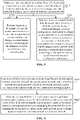
- FIG. 2 is a schematic diagram of another exemplary system architecture.
- the technical solutions provided by the embodiments of the present disclosure may also be applied to the system architecture.
- the system architecture may include a vehicle communication terminal 201, an access network 202, an access network 203, and a core network connected to the access network 202 and the access network 203.
- the quantity of the vehicle communication terminals 201 and the quantity of the networks shown in FIG. 2 are merely schematic. During actual application, the system architecture may include any quantity of vehicle communication terminals 201 and any quantity of networks according to an actual requirement.
- the core network in the system architecture shown in FIG. 2 may be a 5GC network.
- the access network 202 and the access network 203 may be an E-UTRA network and a new radio (NR) network.
- NR new radio
- the access network 203 may be an NR network.
- the access network 203 may be an E-UTRA network.
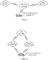
- FIG. 3 shows a variant system architecture of FIG. 2 .
- the core network connected to the access network 202 may be different from the core network connected to the access network 203.
- the core network connected to the access network 202 is the core network 1
- the core network connected to the access network 203 is the core network 2.
- the access network 202 and the access network 203 in the system architecture shown in FIG. 3 may be an E-UTRA network and an NR network.
- the access network 203 may be an NR network.
- the access network 203 may be an E-UTRA network.
- the core network 1 may be an EPC network
- the core network 2 may be a 5GC network.
- the core network 1 may be a 5GC network
- the core network 2 may be an EPC network.
- the access network 202 may determine whether inter-radio access technology-based communication resource control is allowed between an access network entity of the access network 202 and an access network entity of the access network 203. If the inter-radio access technology-based communication resource control is allowed between the access network entity of the access network 202 and the access network entity of the access network 203, the communication resource scheduling may be performed for the vehicle communication terminal 201 by using the access network entity of the access network 202, when the vehicle communication terminal 201 moves from the coverage of the access network 202 to the coverage of the access network 203. It can be learned that, based on the system architecture shown in FIG. 2 or FIG. 3 , the vehicle communication terminal 201 may perform communication by using a scheduling mode.
- the vehicle communication terminal 201 may obtain a communication resource based on a resource pool mode. Specifically, the vehicle communication terminal 201 may determine a supported network mode according to a communication capability of the vehicle communication terminal. If the vehicle communication terminal 201 supports only a network mode of the access network 202, communication may be performed by using a communication resource pool allocated by a network entity of the access network 202, when the vehicle communication terminal 201 moves to the coverage of the access network 203,.
- the vehicle communication terminal 201 supports network modes of both the access network 202 and the access network 203, resource configuration information of the access network 202 is maintained after the vehicle communication terminal 201 moves to the coverage of the access network 203, until a communication resource allocated by a network entity of the access network 203 is obtained. It can be learned that, based on the system architecture shown in FIG. 2 or FIG. 3 , the vehicle communication terminal 201 may perform communication by using a resource pool mode.
- FIG. 4 is a flowchart of a communication method according to an embodiment of the present disclosure.
- the communication method may be performed by a core network entity of a first network.
- the communication method includes at least step S410 and step S420. A detailed description is as follows.
- step S410 communication negotiation is performed with a core network entity of a second network to obtain a communication resource pool allocated by the core network entity of the second network to a terminal device in the first network.
- the first network shares an access network with the second network.
- the core network entity of the first network may perform communication negotiation with core network entities of multiple second networks to obtain respective communication resource pools allocated by the core network entities of the second networks to the terminal device.
- the core network entity of the first network may first determine all second networks existing around, and then perform communication negotiation with core network entities of the second networks existing around to obtain communication resource pools allocated by the core network entities of the second networks to the terminal device.
- the core network entity of the first network may obtain a movement trajectory of the terminal device; then predict, according to the movement trajectory of the terminal device, a network corresponding to a location range to which the terminal device moves as a target second network; and perform communication negotiation with a core network entity of the target second network to obtain a communication resource pool allocated by the core network entity of the target second network to the terminal device. For example, it is assumed that there are a second network 1, a second network 2, and a second network 3 around the first network. If the core network entity of the first network determines, according to the movement trajectory of the terminal device, that a location range to which the terminal device is to move corresponds to the second network 2, the second network 2 may functions as the target second network.
- the core network entity of the first network may then perform communication negotiation with a core network entity of the second network 2 to obtain a communication resource pool allocated by the core network entity of the second network 2 to the terminal device. In this way, a quantity of times of communication between core network entities can be reduced, thereby being beneficial to improve the communication efficiency.
- step S420 the communication resource pool is configured for the terminal device, so that the terminal device performs communication by utilizing a communication resource in the communication resource pool after moving to the second network.
- the terminal device when the terminal device moves to the second network, the terminal device may select a communication resource for data transmission from the communication resource pool to perform communication.
- the technical solution of the embodiment shown in FIG. 4 may be implemented based on the foregoing system architecture shown in FIG. 1 . That is, the first network and the second network may have the same access network and different core networks.
- the core network of the first network is an EPC network
- the core network entity of the first network may be a control function (CF) entity.
- the second network may be a 5G network
- the core network of the second network is a 5GC network
- the core network entity of the second network may be a policy control function (PCF) entity.
- PCF policy control function
- the first network is a 5G network
- the second network may be a 4G network.
- the terminal device 4 may be applied to a scenario in which a terminal device moves from an EPC network using E-UTRA to a 5GC network using E-UTRA, or may be applied to a scenario in which the terminal device moves from the 5GC network using E-UTRA to the EPC network using E-UTRA.
- the terminal device may be a V2X terminal.
- FIG. 5 is a flowchart of another communication method according to an embodiment of the present disclosure.
- the communication method may be performed by an access network entity.
- the access network entity may be an access network entity of a first network.
- the communication method includes at least step S510 to step S530. A detailed description is as follows.
- step S510 as a terminal device is switched from a first network to a second network, it is detected whether an access network entity to which the terminal device is connected changes.
- the first network shares an access network with the second network.
- the terminal device may be connected to the same access network entity or different access network entities as the terminal device is switched from the first network to the second network.
- step S520 in a case that the access network entity to which the terminal device is connected does not change, communication resource scheduling is performed for the terminal device by using the access network entity.
- communication resource scheduling may be performed for the terminal device by using the access network entity. That is, even though a core network may change, the terminal device may still be connected to the same access network entity (such as a base station).
- step S530 in a case that the access network entity to which the terminal device is connected changes, resource configuration information is transmitted to a target access network entity connected to the terminal device by using a source access network entity connected to the terminal device, so that the target access network entity performs communication resource scheduling for the terminal device according to the resource configuration information.
- the source access network entity is an access network entity to which the terminal device is connected in the first network.
- the target access network entity is an access network entity to which the terminal device is connected after the terminal device is switched from the first network to the second network.
- both the first network and the second network support the same radio resource because the first network shares an access network with the second network.
- the resource configuration information can be transmitted to the target access network entity by the source access network entity, so that the target access network entity performs communication resource scheduling for the terminal device according to the resource configuration information.
- the access network shared by the first network and the second network is an E-UTRA network
- both the first network and the second network support E-UTRA radio resources.
- the source access network entity (such as a base station) may transmit PC5 resource configuration information as a handover context to the target access network entity. If the target access network entity determines that continuous communication resource scheduling can be performed, the target access network entity may notify the terminal device, and then perform communication resource scheduling for the terminal device based on the PC5 resource configuration information.
- the technical solution of the embodiment shown in FIG. 5 may be implemented based on the foregoing system architecture shown in FIG. 1 . That is, the first network and the second network may have the same access network and different core networks. For example, if the first network is a 4G network, the second network may be a 5G network. If the first network is a 5G network, the second network may be a 4G network.
- the access networks of the first network and the second network may be E-UTRA networks, and access network entities of both the first network and the second network may be base stations.
- the terminal device may be a V2X terminal.
- FIG. 6 is a flowchart of another communication method according to an embodiment of the present disclosure.
- the communication method may be performed by an access network entity.
- the access network entity may be an access network entity of a third network.
- the communication method includes at least step S610 and step S620. A detailed description is as follows.
- step S610 it is determined whether inter-radio access technology-based communication resource control is allowed between an access network entity of a third network and an access network entity of a fourth network. Access networks of the third network and the fourth network are different.
- core networks of the third network and the fourth network may be the same or different.
- the third network and the fourth network may be respectively an EPC network using E-UTRA and a 5GC network using NR, or may be respectively a 5GC network using E-UTRA and a 5GC network using NR.
- communication negotiation may be performed with the access network entity of the fourth network by using the access network entity of the third network, to determine whether the inter-radio access technology-based communication resource control is allowed between the access network entity of the third network and the access network entity of the fourth network.
- communication negotiation may be performed with a core network entity of the fourth network by using a core network entity of the third network, to determine whether the inter-radio access technology-based communication resource control is allowed between the access network entity of the third network and the access network entity of the fourth network.
- step S620 in a case that the inter-radio access technology-based communication resource control is allowed between the access network entity of the third network and the access network entity of the fourth network, communication resource scheduling is performed for a terminal device by using the access network entity of the third network as the terminal device moves from the third network to the fourth network.
- a communication resource configured by the access network entity of the fourth network may be obtained before the communication resource scheduling is performed for the terminal device by using the access network entity of the third network.
- the access network entity of the third network negotiates with the access network entity of the fourth network in advance, to obtain the communication resource configured by the access network entity of the fourth network.
- the access network entity of the third network may schedule the terminal device to perform communication by utilizing the communication resource configured by the access network entity of the fourth network.
- a handover instruction may be transmitted to the access network entity of the fourth network, so that the access network entity of the fourth network performs the communication resource scheduling for the terminal device after the terminal device accesses the access network entity of the fourth network.
- the terminal device may be controlled to release a communication resource of the third network as the terminal device moves from the third network to the fourth network, and receive a communication resource allocated by the access network entity of the fourth network to the terminal device.
- the technical solution of the embodiment shown in FIG. 6 may be implemented based on the foregoing system architecture shown in FIG. 2 or FIG. 3 . That is, the third network and the fourth network may have the same access network, and may have the same core network or different core networks. Specifically, the technical solution of the embodiment shown in FIG.
- the terminal device may be a V2X terminal.
- FIG. 7 is a flowchart of another communication method according to an embodiment of the present disclosure.
- the communication method may be performed by a terminal device.
- the communication method includes at least step S710 to step S730. A detailed description is as follows.
- step S710 a communication capability of a terminal device is obtained.
- the communication capability of the terminal device may indicate whether the terminal device is a single-mode terminal or a dual-mode terminal. That is, the communication capability of the terminal device indicates whether the terminal device can support network modes of both a third network and a fourth network.
- step S720 in a case that the communication capability indicates that the terminal device supports only a network mode of a third network, communication is performed by using a communication resource pool allocated by a network entity of the third network as the terminal device moves from the third network to the fourth network.
- the communication resource pool allocated by the network entity of the third network is different from a communication resource pool allocated by a network entity of the fourth network.
- the terminal device supports only the network mode of the third network
- communication is performed by using the communication resource pool allocated by the network entity of the third network as the terminal device moves from the third network to the fourth network.
- the communication continuity of the terminal device can be ensured; and on the other hand, coexistence of terminal devices of different network modes in the same network can be implemented.
- step S730 in a case that the communication capability indicates that the terminal device supports network modes of the third network and the fourth network, communication resource configuration information of the third network is maintained as the terminal device moves from the third network to the fourth network, until a communication resource allocated by the network entity of the fourth network is obtained.
- the communication resource that is obtained by the terminal device may be dynamically allocated by the network entity of the fourth network or may be preconfigured.
- the network entity of the fourth network may be an access network entity or a core network entity.
- the technical solution of the embodiment shown in FIG. 7 may be implemented based on the foregoing system architecture shown in FIG. 2 or FIG. 3 . That is, the third network and the fourth network may have the same access network, and may have the same core network or different core networks. Specifically, the technical solution of the embodiment shown in FIG.
- the terminal device 7 may be applied to a scenario in which a terminal device moves from an EPC network using E-UTRA to a 5GC network using NR, or may be applied to a scenario in which the terminal device moves from a 5GC network using E-UTRA to a 5GC network using NR, or may be applied to a scenario in which the terminal device moves from a 5GC network using NR to an EPC network using E-UTRA, or may be applied to a scenario in which the terminal device moves from a 5GC network using NR to a 5GC network using E-UTRA.
- the terminal device may be a V2X terminal.
- Apparatus embodiments of the present disclosure are described hereinafter.
- the apparatus may be used for performing the communication methods in the foregoing embodiments of the present disclosure.
- FIG. 8 is a structural diagram of a communication apparatus according to an embodiment of the present disclosure.
- a communication apparatus 800 includes a communication negotiation unit 802 and a configuration unit 804.
- the communication negotiation unit 802 is configured to perform communication negotiation with a core network entity of a second network to obtain a communication resource pool allocated by the core network entity of the second network to a terminal device in a first network.
- the first network shares an access network with the second network.
- the configuration unit 804 is configured to configure the communication resource pool for the terminal device, so that the terminal device performs communication by utilizing a communication resource in the communication resource pool after moving to the second network.
- the communication negotiation unit 802 is configured to: perform communication negotiation with core network entities of multiple second networks to obtain respective communication resource pools allocated by the core network entities of the multiple second networks to the terminal device.
- the communication negotiation unit 802 is configured to: obtain a movement trajectory of the terminal device; predict, according to the movement trajectory of the terminal device, a network corresponding to a location range to which the terminal device moves as a target second network; and perform communication negotiation with a core network entity of the target second network to obtain a communication resource pool allocated by the core network entity of the target second network to the terminal device.
- the first network and the second network include an EPC network and a 5GC network that share an access network.
- FIG. 9 is a structural diagram of another communication apparatus according to an embodiment of the present disclosure.
- a communication apparatus 900 includes a determining unit 902 and a scheduling unit 904.
- the determining unit 902 is configured to determine whether inter-radio access technology-based communication resource control is allowed between an access network entity of a third network and an access network entity of a fourth network. Access networks of the third network and the fourth network are different.
- the scheduling unit 904 is configured to perform, based on a determination that the inter-radio access technology-based communication resource control is allowed between the access network entity of the third network and the access network entity of the fourth network, communication resource scheduling for a terminal device by using the access network entity of the third network as the terminal device moves from the third network to the fourth network.
- the scheduling unit 904 is further configured to: control, based on a determination that the inter-radio access technology-based communication resource control is not allowed between the access network entity of the third network and the access network entity of the fourth network, the terminal device to release a communication resource of the third network as the terminal device moves from the third network to the fourth network and receive a communication resource allocated by the access network entity of the fourth network to the terminal device.
- the communication apparatus 900 further includes: an obtaining unit, configured to obtain, before the communication resource scheduling is performed for the terminal device by using the access network entity of the third network, a communication resource configured by the access network entity of the fourth network.
- the process of performing the communication resource scheduling for the terminal device by using the access network entity of the third network by the scheduling unit 904 includes: scheduling, by using the access network entity of the third network, the terminal device to perform communication by utilizing the communication resource configured by the access network entity of the fourth network.
- the communication apparatus 900 further includes: a transmission unit, configured to transmit, after the communication resource scheduling is performed for the terminal device by using the access network entity of the third network, a handover instruction to the access network entity of the fourth network, so that the access network entity of the fourth network performs the communication resource scheduling for the terminal device after the terminal device accesses the access network entity of the fourth network.
- the determining unit 902 is configured to: perform communication negotiation with the access network entity of the fourth network by using the access network entity of the third network, to determine whether the inter-radio access technology-based communication resource control is allowed between the access network entity of the third network and the access network entity of the fourth network; or perform communication negotiation with a core network entity of the fourth network by using a core network entity of the third network, to determine whether the inter-radio access technology-based communication resource control is allowed between the access network entity of the third network and the access network entity of the fourth network.
- the third network and the fourth network include an EPC network and a 5GC network that have different access networks, or the third network and the fourth network include 5GC networks having different access networks.
- FIG. 10 is a structural diagram of another communication apparatus according to an embodiment of the present disclosure.
- a communication apparatus 1000 includes an obtaining unit 1002 and a processing unit 1004.
- the obtaining unit 1002 is configured to obtain a communication capability of a terminal device.
- the processing unit 1004 is configured to perform, in a case that the communication capability indicates that the terminal device supports only a network mode of a third network, communication by using a communication resource pool allocated by a network entity of the third network as the terminal device moves from the third network to a fourth network, where the communication resource pool allocated by the network entity of the third network is different from a communication resource pool allocated by a network entity of the fourth network; and maintain, in a case that the communication capability indicates that the terminal device supports network modes of the third network and the fourth network, communication resource configuration information of the third network as the terminal device moves from the third network to the fourth network, until a communication resource allocated by the network entity of the fourth network is obtained.
- FIG. 11 is a structural diagram of another communication apparatus according to an embodiment of the present disclosure.
- a communication apparatus 1100 includes a detection unit 1102 and a scheduling unit 1104.
- the detection unit 1102 is configured to detect, as a terminal device is switched from a first network to a second network, whether an access network entity to which the terminal device is connected changes.
- the first network shares an access network with the second network.
- the scheduling unit 1104 is configured to: perform, in a case that the access network entity to which the terminal device is connected does not change, communication resource scheduling for the terminal device by using the access network entity; and transmit, in a case that the access network entity to which the terminal device is connected changes, resource configuration information to a target access network entity to which the terminal device is connected by using a source access network entity to which the terminal device is connected, so that the target access network entity performs communication resource scheduling for the terminal device according to the resource configuration information.
- the source access network entity is an access network entity to which the terminal device is connected in the first network
- the target access network entity is an access network entity to which the terminal device is connected in the second network.
- FIG. 12 is a schematic structural diagram of a computer system for implementing an electronic device according to the embodiment of the present disclosure.
- a computer system 1200 for implementing the electronic device shown in FIG. 12 is merely schematic, and does not constitute any limitation on functions and application ranges of the embodiments of the present disclosure.
- the computer system 1200 includes a central processing unit (CPU) 1201, which may perform various suitable actions and processing based on a program stored in a read-only memory (ROM) 1202 or a program loaded from a storage part 1208 into a random access memory (RAM) 1203, for example, perform the method described in the foregoing embodiments.
- the RAM 1203 further stores various programs and data required for system operations.
- the CPU 1201, the ROM 1202, and the RAM 1203 are connected to each other through a bus 1204.
- An input/output (I/O) interface 1205 is also connected to the bus 1204.
- the following components are connected to the I/O interface 1205: an input part 1206 including a keyboard, a mouse, or the like; an output part 1207 including a cathode ray tube (CRT), a liquid crystal display (LCD), a speaker, or the like; a storage part 1208 including a hard disk, or the like; and a communication part 1209 including a network interface card such as a local area network (LAN) card or a modem.
- the communication part 1209 performs communication processing through a network such as the Internet.
- a driver 1210 is also connected to the I/O interface 1205 as required.
- a removable medium 1211 such as a magnetic disk, an optical disc, a magneto-optical disk, or a semiconductor memory is installed on the drive 1210 as required, so that a computer program read from the removable medium is installed into the storage part 1208 as required.
- the processes described above with reference to the flowcharts may be implemented as computer software programs.
- a computer program product is provided according to an embodiment of the present disclosure.
- the computer program product includes a computer program stored in a computer-readable medium.
- the computer program includes a computer program used for performing a method shown in the flowchart.
- the computer program may be downloaded and installed from a network through the communication part 1209, and/or installed from the removable medium 1211.
- the various functions defined in the system of the present disclosure are executed.
- the computer-readable medium shown in the embodiments of the present disclosure may be a computer-readable signal medium or a computer-readable storage medium or any combination thereof.
- the computer-readable storage medium may be, for example, but is not limited to, an electrical, magnetic, optical, electromagnetic, infrared, or semiconductor system, apparatus, or device, or any combination thereof.
- Examples of the computer-readable storage medium may include but are not limited to: an electrical connection having one or more wires, a portable computer magnetic disk, a hard disk, a RAM, a ROM, an erasable programmable read-only memory (EPROM), a flash memory, an optical fiber, a compact disk read-only memory (CD-ROM), an optical storage device, a magnetic storage device, or any appropriate combination thereof.
- the computer-readable storage medium may be any tangible medium containing or storing a program, and the program may be used by or used in combination with an instruction execution system, an apparatus, or a device.
- the computer-readable signal medium may include a data signal transmitted in a baseband or as part of a carrier, and stores a computer-readable program.
- a data signal propagated in such a way may be in multiple forms, including, but not limited to, an electromagnetic signal, an optical signal, or any appropriate combination thereof.
- the computer-readable signal medium may be any computer-readable medium other than the computer-readable storage medium.
- the computer-readable medium may send, propagate, or transmit a program configured to be used by or in combination with an instruction execution system, an apparatus, or a device.
- the computer program included in the computer-readable medium may be transmitted by using any suitable medium, including but not limited to: a wireless medium, a wired medium, or the like, or any suitable combination thereof.
- Each box in a flowchart or a block diagram may represent a module, a program segment, or a part of code.
- the module, the program segment, or the part of code includes one or more executable instructions used for implementing specified logic functions.
- functions annotated in boxes may be performed in a sequence different from that annotated in the accompanying drawing. For example, two boxes shown in succession may be performed substantially in parallel, and sometimes the two boxes may be performed in a reverse sequence. This depends on a related function.
- Each box in a block diagram or a flowchart and a combination of boxes in the block diagram or the flowchart may be implemented by using a dedicated hardware-based system configured to perform a designated function or operation, or may be implemented by using a combination of dedicated hardware and a computer instruction.
- a related unit described in the embodiments of the present disclosure may be implemented in a software manner, or may be implemented in a hardware manner.
- the unit described may be arranged in a processor. Names of these units do not constitute a limitation on the units in some cases.
- a computer-readable medium is further provided according to the present disclosure.
- the computer-readable medium may be included in the electronic device described in the foregoing embodiments, or may exist alone and is not installed in the electronic device.
- the computer-readable medium carries one or more programs. The one or more programs, when executed by the electronic device, cause the electronic device to implement the method described in the foregoing embodiments.
- the software product may be stored in a non-volatile storage medium (which may be a CD-ROM, a USB flash drive, a removable hard disk, or the like) or on the network, including several instructions for instructing a computing device (which may be a personal computer, a server, a touch terminal, a network device, or the like) to perform the methods according to the embodiments of the present disclosure.
- a non-volatile storage medium which may be a CD-ROM, a USB flash drive, a removable hard disk, or the like
- a computing device which may be a personal computer, a server, a touch terminal, a network device, or the like
Landscapes
- Engineering & Computer Science (AREA)
- Computer Networks & Wireless Communication (AREA)
- Signal Processing (AREA)
- Quality & Reliability (AREA)
- Mobile Radio Communication Systems (AREA)
Abstract
Description
- This application claims priority to
Chinese Patent Application No. 201910523813.1, titled "COMMUNICATION METHOD AND APPARATUS, COMPUTER-READABLE MEDIUM, AND ELECTRONIC DEVICE" filed with the National Intellectual Property Administration, PRC on June 17, 2019 - The present disclosure relates to the technical field of computers and communication, and particularly to a communication technology.
- A terminal device obtains a communication resource by a scheduling mode and a resource pool mode. If the terminal device remains within the coverage of one network, a communication resource can be obtained conveniently within the coverage of the network. However, if the terminal device moves between the coverage of different networks, for example, a vehicle to everything (V2X) terminal moves from the coverage of a 4G network to the coverage of a 5G network, how to ensure the communication continuity of the terminal device becomes a technical problem to be urgently resolved.
- According to embodiments of the present disclosure, a communication method and apparatus, a computer-readable medium, and an electronic device are provided, to ensure the communication continuity to a certain degree during network handover of a terminal device, so as to improve the communication efficiency of the terminal device.
- Other features and advantages of the present disclosure become obvious through the following detailed descriptions, or may be partially learned through the practice of the present disclosure.
- According to an aspect of the embodiments of the present disclosure, a communication method is provided. The method is performed by a core network entity of a first network. The method includes:
- performing communication negotiation with a core network entity of a second network to obtain a communication resource pool allocated by the core network entity of the second network to a terminal device in the first network, where the first network shares an access network with the second network; and
- configuring the communication resource pool for the terminal device, so that the terminal device performs communication by utilizing a communication resource in the communication resource pool after moving to the second network.
- According to an aspect of the embodiments of the present disclosure, a communication method is provided. The method is performed by an access network entity. The method includes:
- determining whether inter-radio access technology-based communication resource control is allowed between an access network entity of a third network and an access network entity of a fourth network, where access networks of the third network and the fourth network are different; and
- performing, based on a determination that the inter-radio access technology-based communication resource control is allowed between the access network entity of the third network and the access network entity of the fourth network, communication resource scheduling for a terminal device by utilizing the access network entity of the third network as the terminal device moves from the third network to the fourth network.
- According to an aspect of the embodiments of the present disclosure, a communication method is provided. The method is performed by a terminal device. The method includes:
- obtaining a communication capability of the terminal device;
- performing, in a case that the communication capability indicates that the terminal device supports only a network mode of a third network, communication by utilizing a communication resource pool allocated by a network entity of the third network as the terminal device moves from the third network to a fourth network, where the communication resource pool allocated by the network entity of the third network is different from a communication resource pool allocated by a network entity of the fourth network; and
- maintaining, in a case that the communication capability indicates that the terminal device supports network modes of the third network and the fourth network, communication resource configuration information of the third network as the terminal device moves from the third network to the fourth network, until a communication resource allocated by the network entity of the fourth network is obtained.
- According to an aspect of the embodiments of the present disclosure, a communication method is provided. The method is performed by an access network entity. The method includes:
- detecting, as a terminal device is switched from a first network to a second network, whether an access network entity to which the terminal device is connected changes, where the first network shares an access network with the second network;
- performing, in a case that the access network entity to which the terminal device is connected does not change, communication resource scheduling for the terminal device by utilizing the access network entity; and
- transmitting, in a case that the access network entity to which the terminal device is connected changes, resource configuration information to a target access network entity connected to the terminal device by utilizing a source access network entity connected to the terminal device, so that the target access network entity performs communication resource scheduling for the terminal device according to the resource configuration information, the source access network entity is an access network entity to which the terminal device is connected in the first network, and the target access network entity is an access network entity to which the terminal device is connected in the second network.
- According to an aspect of the embodiments of the present disclosure, a communication apparatus is provided. The apparatus includes a communication negotiation unit and a configuration unit.
- The communication negotiation unit is configured to perform communication negotiation with a core network entity of a second network to obtain a communication resource pool allocated by the core network entity of the second network to a terminal device in a first network. The first network shares an access network with the second network.
- The configuration unit is configured to configure the communication resource pool for the terminal device, so that the terminal device performs communication by utilizing a communication resource in the communication resource pool after moving to the second network.
- According to an aspect of the embodiments of the present disclosure, a communication apparatus is provided. The apparatus includes a determining unit and a scheduling unit.
- The determining unit is configured to determine whether inter-radio access technology-based communication resource control is allowed between an access network entity of a third network and an access network entity of a fourth network. Access networks of the third network and the fourth network are different.
- The scheduling unit is configured to perform, based on a determination that the inter-radio access technology-based communication resource control is allowed between the access network entity of the third network and the access network entity of the fourth network, communication resource scheduling for a terminal device by utilizing the access network entity of the third network as the terminal device moves from the third network to the fourth network.
- According to an aspect of the embodiments of the present disclosure, a communication apparatus is provided. The apparatus includes an obtaining unit, a processing unit and a scheduling unit.
- The obtaining unit is configured to obtain a communication capability of a terminal device.
- The processing unit is configured to perform, in a case that the communication capability indicates that the terminal device supports only a network mode of a third network, communication by utilizing a communication resource pool allocated by a network entity of the third network as the terminal device moves from the third network to a fourth network, where the communication resource pool allocated by the network entity of the third network is different from a communication resource pool allocated by a network entity of the fourth network; and maintain, in a case that the communication capability indicates that the terminal device supports network modes of the third network and the fourth network, communication resource configuration information of the third network as the terminal device moves from the third network to the fourth network, until a communication resource allocated by the network entity of the fourth network is obtained.
- According to an aspect of the embodiments of the present disclosure, a communication apparatus is provided. The apparatus includes a detection unit and a scheduling unit.
- The detection unit is configured to detect, as a terminal device is switched from a first network to a second network, whether an access network entity to which the terminal device is connected changes. The first network shares an access network with the second network.
- The scheduling unit is configured to perform, in a case that the access network entity to which the terminal device is connected does not change, communication resource scheduling for the terminal device by utilizing the access network entity; and transmit, in a case that the access network entity to which the terminal device is connected changes, resource configuration information to a target access network entity connected to the terminal device by utilizing a source access network entity connected to the terminal device, so that the target access network entity performs communication resource scheduling for the terminal device according to the resource configuration information. The source access network entity is an access network entity to which the terminal device is connected in the first network, and the target access network entity is an access network entity to which the terminal device is connected in the second network.
- According to an aspect of the embodiments of the present disclosure, a computer-readable medium is provided, which stores a computer program. The computer program, when executed by a processor, implements the communication method according to the foregoing embodiments.
- According to an aspect of the embodiments of the present disclosure, an electronic device is provided. The electronic device includes: one or more processors; and a storage apparatus, configured to store one or more programs. The one or more programs, when executed by the one or more processors, cause the one or more processors to implement the communication method according to the foregoing embodiments.
- According to an aspect of the embodiments of the present disclosure, a computer program product is further provided, which includes instructions. The instructions, when run on a computer, cause the computer to perform the communication method according to the foregoing embodiments.
- In the technical solutions provided by some embodiments of the present disclosure, the core network entity of the first network obtains, by performing communication negotiation with the core network entity of the second network that shares an access network with the first network, the communication resource pool allocated by the core network entity of the second network to the terminal device in the first network. Further, the core network entity of the first network configures, for the terminal device, the communication resource pool allocated by the core network entity of the second network, so as to allocate the communication resource pool to the terminal device in advance before the terminal device moves to the second network, so that the terminal device can perform communication by directly utilizing the communication resource in the communication resource pool after moving to the second network. In this way, the communication continuity during network handover of the terminal device can be ensured, thereby being beneficial to improve the communication efficiency of the terminal device.
- In the technical solutions provided by some embodiments of the present disclosure, in a case that the inter-radio access technology-based communication resource control is allowed between the access network entity of the third network and the access network entity of the fourth network that has a different access network from that of the third network, the communication resource scheduling is performed for the terminal device by utilizing the access network entity of the third network as the terminal device moves from the third network to the fourth network, so as to ensure the communication continuity during network handover of the terminal device in a case that the inter-radio access technology-based communication resource control is supported at a network side, thereby being beneficial to improve the communication efficiency of the terminal device.
- In the technical solutions provided by some embodiments of the present disclosure, the communication capability of the terminal device is obtained. In a case that the terminal device supports only the network mode of the third network, communication is performed by utilizing the communication resource pool allocated by the network entity of the third network as the terminal device moves from the third network to the fourth network, so that the terminal device can perform communication by using a communication resource pool of an original network during network handover of the terminal device, thereby ensuring the communication continuity of the terminal device, and also implementing coexistence of terminal devices of different network modes in the same network. In addition, in a case that the terminal device supports network modes of the third network and the fourth network, communication resource configuration information of the third network is maintained as the terminal device moves from the third network to the fourth network, until a communication resource allocated by the network entity of the fourth network is obtained. In this way, the communication continuity of the terminal device can also be ensured during the network handover of the terminal device, thereby being beneficial to improve the communication efficiency of the terminal device.
- In technical solutions provided by some embodiments of the present disclosure, in a case that the access network entity to which the terminal device is connected does not change as the terminal device is switched from the first network to the second network that shares an access network with the first network, communication resource scheduling continues is performed for the terminal device by utilizing the access network entity, so that resource scheduling can be performed for the terminal device during network handover by using the same access network entity, thereby ensuring the communication continuity of the terminal device. In addition, in a case that the access network entity to which the terminal device is connected changes, the communication resource configuration information is transmitted to the target access network entity connected to the terminal device by using the source access network entity connected to the terminal device, so that the communication resource scheduling can be performed for the terminal device by using the target access network entity, and thus the communication continuity during network handover can also be implemented.
- It is to be understood that, the foregoing general descriptions and the following detailed descriptions are merely for illustration and explanation purposes and are not intended to limit the present disclosure.
- Accompanying drawings herein are incorporated into this specification and constitute a part of this specification, show embodiments that conform to the present disclosure, and are used for describing a principle of the present disclosure together with this specification. Apparently, the accompanying drawings described below show merely some embodiments of the present disclosure, and a person of ordinary skill in the art may obtain other accompanying drawings according to the accompanying drawings without creative efforts. In the accompanying drawings:
-
FIG. 1 is a schematic diagram of an exemplary system architecture to which a technical solution according to an embodiment of the present disclosure may be applied. -
FIG. 2 is a schematic diagram of an exemplary system architecture to which a technical solution according to an embodiment of the present disclosure may be applied. -
FIG. 3 is a schematic diagram of an exemplary system architecture to which a technical solution according to an embodiment of the present disclosure may be applied. -
FIG. 4 is a flowchart of a communication method according to an embodiment of the present disclosure. -
FIG. 5 is a flowchart of a communication method according to an embodiment of the present disclosure. -
FIG. 6 is a flowchart of a communication method according to an embodiment of the present disclosure. -
FIG. 7 is a flowchart of a communication method according to an embodiment of the present disclosure. -
FIG. 8 is a structural diagram of a communication apparatus according to an embodiment of the present disclosure. -
FIG. 9 is a structural diagram of a communication apparatus according to an embodiment of the present disclosure. -
FIG. 10 is a structural diagram of a communication apparatus according to an embodiment of the present disclosure. -
FIG. 11 is a structural diagram of a communication apparatus according to an embodiment of the present disclosure. -
FIG. 12 is a schematic structural diagram of a computer system for implementing an electronic device according to an embodiment of the present disclosure. - At present, the exemplary implementations are described more comprehensively with reference to the accompanying drawings. However, the exemplary implementations may be implemented in multiple forms, and should not be understood as being limited to the examples described herein. Conversely, the implementations are provided to make the present disclosure more comprehensive and complete, and comprehensively convey the concept of the exemplary implementations to a person skilled in the art.
- In addition, the described characteristics, structures, or features may be combined in one or more embodiments in any appropriate manner. In the following descriptions, a lot of specific details are provided to provide a comprehensive understanding of the embodiments of the present disclosure. However, a person of ordinary skill in the art is to be aware that, the technical solutions in the present disclosure may be implemented without one or more of the particular details, or another method, unit, apparatus, or step may be used. In other cases, well-known methods, apparatuses, implementations, or operations are not shown or described in detail, to avoid obscuring the aspects of the present disclosure.
- The blocks shown in the accompanying drawings represent merely functional entities and do not necessarily correspond to physically independent entities. That is, the functional entities may be implemented in a software form, or in one or more hardware modules or integrated circuits, or in different networks and/or processor apparatuses and/or microcontroller apparatuses.
- The flowcharts shown in the accompanying drawings are merely exemplary descriptions and do not necessarily include all of the content and operations/steps, nor are the flowcharts necessarily performed in the order described. For example, some operations/steps may be divided, while some operations/steps may be combined or partially combined. Therefore, an actual execution order may change according to an actual case.
-
FIG. 1 is a schematic diagram of an exemplary system architecture. The technical solutions provided by the embodiments of the present disclosure may be applied to the system architecture. - As shown in
FIG. 1 , the system architecture may include avehicle communication terminal 101 and two networks that share an access network. Core networks of the two networks are respectively acore network 1 and acore network 2. - It is to be understood that, the quantity of the
vehicle communication terminals 101 and the quantity of the networks shown inFIG. 1 are merely schematic. During actual application, the system architecture may include any quantity ofvehicle communication terminals 101 and any quantity of networks according to an actual requirement. - In an embodiment of the present disclosure, in a case that the
vehicle communication terminal 101 is within the coverage of the core network 1 (that is, interacts with thecore network 1 over the access network), a core network entity of thecore network 1 may perform communication negotiation with a core network entity of thecore network 2, to obtain a communication resource pool allocated by the core network entity of thecore network 2 to thevehicle communication terminal 101. Next, the core network entity of thecore network 1 may configure, for thevehicle communication terminal 101 by using the access network, the communication resource pool allocated by the core network entity of thecore network 2, so that thevehicle communication terminal 101 performs communication by utilizing a communication resource in the communication resource pool after moving to the coverage of thecore network 2. It can be learned that, based on the system architecture shown inFIG. 1 , thevehicle communication terminal 101 may perform communication by using a resource pool mode. - In an embodiment of the present disclosure, based on the system architecture shown in
FIG. 1 , thevehicle communication terminal 101 may obtain a communication resource based on a scheduling mode. Specifically, the access network may detect, as thevehicle communication terminal 101 moves from the coverage of thecore network 1 to the coverage of thecore network 2, whether an access network entity connected to thevehicle communication terminal 101 changes. If the access network entity to which thevehicle communication terminal 101 is connected does not change, communication resource scheduling is performed for thevehicle communication terminal 101 by using the access network entity connected to thevehicle communication terminal 101. If the access network entity to which thevehicle communication terminal 101 is connected changes, resource configuration information is transmitted to a target access network entity connected to the vehicle communication terminal 101 (that is, an access network entity to which thevehicle communication terminal 101 is connected after thevehicle communication terminal 101 moves to the coverage of the core network 2) by using a source access network entity connected to the vehicle communication terminal 101 (that is, an access network entity to which thevehicle communication terminal 101 is connected in a case that thevehicle communication terminal 101 is within the coverage of the core network 1), so that the target access network entity performs the communication resource scheduling for thevehicle communication terminal 101 according to the resource configuration information. It can be learned that, based on the system architecture shown inFIG. 1 , thevehicle communication terminal 101 may perform communication by using a scheduling mode. - The access network in the system architecture shown in
FIG. 1 may be an evolved universal terrestrial radio access (E-UTRA) network, and thecore network 1 and thecore network 2 may be an evolved packet core (EPC) network and a 5G core (5GC) network. For example, if thecore network 1 is an EPC network, thecore network 2 may be a 5GC network. If thecore network 1 is a 5GC network, thecore network 2 may be an EPC network. -
FIG. 2 is a schematic diagram of another exemplary system architecture. The technical solutions provided by the embodiments of the present disclosure may also be applied to the system architecture. - As shown in
FIG. 2 , the system architecture may include avehicle communication terminal 201, anaccess network 202, anaccess network 203, and a core network connected to theaccess network 202 and theaccess network 203. - It is to be understood that, the quantity of the
vehicle communication terminals 201 and the quantity of the networks shown inFIG. 2 are merely schematic. During actual application, the system architecture may include any quantity ofvehicle communication terminals 201 and any quantity of networks according to an actual requirement. - The core network in the system architecture shown in
FIG. 2 may be a 5GC network. Theaccess network 202 and theaccess network 203 may be an E-UTRA network and a new radio (NR) network. For example, if theaccess network 202 is an E-UTRA network, theaccess network 203 may be an NR network. If theaccess network 202 is an NR network, theaccess network 203 may be an E-UTRA network. -
FIG. 3 shows a variant system architecture ofFIG. 2 . As shown inFIG. 3 , the core network connected to theaccess network 202 may be different from the core network connected to theaccess network 203. For example, the core network connected to theaccess network 202 is thecore network 1, and the core network connected to theaccess network 203 is thecore network 2. - The
access network 202 and theaccess network 203 in the system architecture shown inFIG. 3 may be an E-UTRA network and an NR network. For example, if theaccess network 202 is an E-UTRA network, theaccess network 203 may be an NR network. If theaccess network 202 is an NR network, theaccess network 203 may be an E-UTRA network. If theaccess network 202 is an E-UTRA network and theaccess network 203 is an NR network, thecore network 1 may be an EPC network, and thecore network 2 may be a 5GC network. If theaccess network 202 is an NR network and theaccess network 203 is an E-UTRA network, thecore network 1 may be a 5GC network, and thecore network 2 may be an EPC network. - Based on the system architecture shown in
FIG. 2 orFIG. 3 , in an embodiment of the present disclosure, in a case that thevehicle communication terminal 201 is within the coverage of theaccess network 202, theaccess network 202 may determine whether inter-radio access technology-based communication resource control is allowed between an access network entity of theaccess network 202 and an access network entity of theaccess network 203. If the inter-radio access technology-based communication resource control is allowed between the access network entity of theaccess network 202 and the access network entity of theaccess network 203, the communication resource scheduling may be performed for thevehicle communication terminal 201 by using the access network entity of theaccess network 202, when thevehicle communication terminal 201 moves from the coverage of theaccess network 202 to the coverage of theaccess network 203. It can be learned that, based on the system architecture shown inFIG. 2 orFIG. 3 , thevehicle communication terminal 201 may perform communication by using a scheduling mode. - In an embodiment of the present disclosure, based on the system architecture shown in
FIG. 2 orFIG. 3 , thevehicle communication terminal 201 may obtain a communication resource based on a resource pool mode. Specifically, thevehicle communication terminal 201 may determine a supported network mode according to a communication capability of the vehicle communication terminal. If thevehicle communication terminal 201 supports only a network mode of theaccess network 202, communication may be performed by using a communication resource pool allocated by a network entity of theaccess network 202, when thevehicle communication terminal 201 moves to the coverage of theaccess network 203,. If thevehicle communication terminal 201 supports network modes of both theaccess network 202 and theaccess network 203, resource configuration information of theaccess network 202 is maintained after thevehicle communication terminal 201 moves to the coverage of theaccess network 203, until a communication resource allocated by a network entity of theaccess network 203 is obtained. It can be learned that, based on the system architecture shown inFIG. 2 orFIG. 3 , thevehicle communication terminal 201 may perform communication by using a resource pool mode. - The implementation details of the technical solution of this embodiment of the present disclosure are described in detail in the following.
-
FIG. 4 is a flowchart of a communication method according to an embodiment of the present disclosure. The communication method may be performed by a core network entity of a first network. Referring toFIG. 4 , the communication method includes at least step S410 and step S420. A detailed description is as follows. - In step S410, communication negotiation is performed with a core network entity of a second network to obtain a communication resource pool allocated by the core network entity of the second network to a terminal device in the first network. The first network shares an access network with the second network.
- In an embodiment of the present disclosure, the core network entity of the first network may perform communication negotiation with core network entities of multiple second networks to obtain respective communication resource pools allocated by the core network entities of the second networks to the terminal device. For example, the core network entity of the first network may first determine all second networks existing around, and then perform communication negotiation with core network entities of the second networks existing around to obtain communication resource pools allocated by the core network entities of the second networks to the terminal device.
- In an embodiment of the present disclosure, the core network entity of the first network may obtain a movement trajectory of the terminal device; then predict, according to the movement trajectory of the terminal device, a network corresponding to a location range to which the terminal device moves as a target second network; and perform communication negotiation with a core network entity of the target second network to obtain a communication resource pool allocated by the core network entity of the target second network to the terminal device. For example, it is assumed that there are a
second network 1, asecond network 2, and a second network 3 around the first network. If the core network entity of the first network determines, according to the movement trajectory of the terminal device, that a location range to which the terminal device is to move corresponds to thesecond network 2, thesecond network 2 may functions as the target second network. The core network entity of the first network may then perform communication negotiation with a core network entity of thesecond network 2 to obtain a communication resource pool allocated by the core network entity of thesecond network 2 to the terminal device. In this way, a quantity of times of communication between core network entities can be reduced, thereby being beneficial to improve the communication efficiency. - Reference is made to
FIG. 4 again. In step S420, the communication resource pool is configured for the terminal device, so that the terminal device performs communication by utilizing a communication resource in the communication resource pool after moving to the second network. - In an embodiment of the present disclosure, when the terminal device moves to the second network, the terminal device may select a communication resource for data transmission from the communication resource pool to perform communication.
- The technical solution of the embodiment shown in
FIG. 4 may be implemented based on the foregoing system architecture shown inFIG. 1 . That is, the first network and the second network may have the same access network and different core networks. For example, if the first network is a 4G network, the core network of the first network is an EPC network, and the core network entity of the first network may be a control function (CF) entity. The second network may be a 5G network, the core network of the second network is a 5GC network, and the core network entity of the second network may be a policy control function (PCF) entity. Similarly, if the first network is a 5G network, the second network may be a 4G network. Specifically, the technical solution of the embodiment shown inFIG. 4 may be applied to a scenario in which a terminal device moves from an EPC network using E-UTRA to a 5GC network using E-UTRA, or may be applied to a scenario in which the terminal device moves from the 5GC network using E-UTRA to the EPC network using E-UTRA. The terminal device may be a V2X terminal. -
FIG. 5 is a flowchart of another communication method according to an embodiment of the present disclosure. The communication method may be performed by an access network entity. For example, the access network entity may be an access network entity of a first network. Referring toFIG. 5 , the communication method includes at least step S510 to step S530. A detailed description is as follows. - In step S510, as a terminal device is switched from a first network to a second network, it is detected whether an access network entity to which the terminal device is connected changes. The first network shares an access network with the second network.
- In an embodiment of the present disclosure, if the first network shares an access network with the second network, the terminal device may be connected to the same access network entity or different access network entities as the terminal device is switched from the first network to the second network.
- In step S520, in a case that the access network entity to which the terminal device is connected does not change, communication resource scheduling is performed for the terminal device by using the access network entity.
- In an embodiment of the present disclosure, if the access network entity to which the terminal device is connected does not change as the terminal device is switched from the first network to the second network, communication resource scheduling may be performed for the terminal device by using the access network entity. That is, even though a core network may change, the terminal device may still be connected to the same access network entity (such as a base station).
- In step S530, in a case that the access network entity to which the terminal device is connected changes, resource configuration information is transmitted to a target access network entity connected to the terminal device by using a source access network entity connected to the terminal device, so that the target access network entity performs communication resource scheduling for the terminal device according to the resource configuration information.
- Herein, the source access network entity is an access network entity to which the terminal device is connected in the first network. The target access network entity is an access network entity to which the terminal device is connected after the terminal device is switched from the first network to the second network.
- In an embodiment of the present disclosure, if the access network entity to which the terminal device is connected changes as the terminal device is switched from the first network to the second network, both the first network and the second network support the same radio resource because the first network shares an access network with the second network. The resource configuration information can be transmitted to the target access network entity by the source access network entity, so that the target access network entity performs communication resource scheduling for the terminal device according to the resource configuration information. For example, if the access network shared by the first network and the second network is an E-UTRA network, both the first network and the second network support E-UTRA radio resources. Furthermore, the source access network entity (such as a base station) may transmit PC5 resource configuration information as a handover context to the target access network entity. If the target access network entity determines that continuous communication resource scheduling can be performed, the target access network entity may notify the terminal device, and then perform communication resource scheduling for the terminal device based on the PC5 resource configuration information.
- The technical solution of the embodiment shown in
FIG. 5 may be implemented based on the foregoing system architecture shown inFIG. 1 . That is, the first network and the second network may have the same access network and different core networks. For example, if the first network is a 4G network, the second network may be a 5G network. If the first network is a 5G network, the second network may be a 4G network. The access networks of the first network and the second network may be E-UTRA networks, and access network entities of both the first network and the second network may be base stations. Specifically, the technical solution of the embodiment shown inFIG. 5 may be applied to a scenario in which a terminal device moves from an EPC network using E-UTRA to a 5GC network using E-UTRA, or may be applied to a scenario in which the terminal device moves from the 5GC network using E-UTRA to the EPC network using E-UTRA. The terminal device may be a V2X terminal. -
FIG. 6 is a flowchart of another communication method according to an embodiment of the present disclosure. The communication method may be performed by an access network entity. For example, the access network entity may be an access network entity of a third network. Referring toFIG. 6 , the communication method includes at least step S610 and step S620. A detailed description is as follows. - In step S610, it is determined whether inter-radio access technology-based communication resource control is allowed between an access network entity of a third network and an access network entity of a fourth network. Access networks of the third network and the fourth network are different.
- In an embodiment of the present disclosure, in a case that the access networks of the third network and the fourth network are different, core networks of the third network and the fourth network may be the same or different. For example, the third network and the fourth network may be respectively an EPC network using E-UTRA and a 5GC network using NR, or may be respectively a 5GC network using E-UTRA and a 5GC network using NR.
- In an embodiment of the present disclosure, communication negotiation may be performed with the access network entity of the fourth network by using the access network entity of the third network, to determine whether the inter-radio access technology-based communication resource control is allowed between the access network entity of the third network and the access network entity of the fourth network.
- In an embodiment of the present disclosure, communication negotiation may be performed with a core network entity of the fourth network by using a core network entity of the third network, to determine whether the inter-radio access technology-based communication resource control is allowed between the access network entity of the third network and the access network entity of the fourth network.
- In step S620, in a case that the inter-radio access technology-based communication resource control is allowed between the access network entity of the third network and the access network entity of the fourth network, communication resource scheduling is performed for a terminal device by using the access network entity of the third network as the terminal device moves from the third network to the fourth network.
- In an embodiment of the present disclosure, before the communication resource scheduling is performed for the terminal device by using the access network entity of the third network, a communication resource configured by the access network entity of the fourth network may be obtained. For example, the access network entity of the third network negotiates with the access network entity of the fourth network in advance, to obtain the communication resource configured by the access network entity of the fourth network. Furthermore, the access network entity of the third network may schedule the terminal device to perform communication by utilizing the communication resource configured by the access network entity of the fourth network.
- In an embodiment of the present disclosure, after the communication resource scheduling is performed for the terminal device by using the access network entity of the third network, a handover instruction may be transmitted to the access network entity of the fourth network, so that the access network entity of the fourth network performs the communication resource scheduling for the terminal device after the terminal device accesses the access network entity of the fourth network.
- In an embodiment of the present disclosure, if the inter-radio access technology-based communication resource control is not allowed between the access network entity of the third network and the access network entity of the fourth network, the terminal device may be controlled to release a communication resource of the third network as the terminal device moves from the third network to the fourth network, and receive a communication resource allocated by the access network entity of the fourth network to the terminal device.
- The technical solution of the embodiment shown in
FIG. 6 may be implemented based on the foregoing system architecture shown inFIG. 2 orFIG. 3 . That is, the third network and the fourth network may have the same access network, and may have the same core network or different core networks. Specifically, the technical solution of the embodiment shown inFIG. 6 may be applied to a scenario in which a terminal device moves from an EPC network using E-UTRA to a 5GC network using NR, or may be applied to a scenario in which the terminal device moves from a 5GC network using E-UTRA to a 5GC network using NR, or may be applied to a scenario in which the terminal device moves from a 5GC network using NR to an EPC network using E-UTRA, or may be applied to a scenario in which the terminal device moves from a 5GC network using NR to a 5GC network using E-UTRA. The terminal device may be a V2X terminal. -
FIG. 7 is a flowchart of another communication method according to an embodiment of the present disclosure. The communication method may be performed by a terminal device. Referring toFIG. 7 , the communication method includes at least step S710 to step S730. A detailed description is as follows. - In step S710, a communication capability of a terminal device is obtained.
- In an embodiment of the present disclosure, the communication capability of the terminal device may indicate whether the terminal device is a single-mode terminal or a dual-mode terminal. That is, the communication capability of the terminal device indicates whether the terminal device can support network modes of both a third network and a fourth network.
- In step S720, in a case that the communication capability indicates that the terminal device supports only a network mode of a third network, communication is performed by using a communication resource pool allocated by a network entity of the third network as the terminal device moves from the third network to the fourth network. The communication resource pool allocated by the network entity of the third network is different from a communication resource pool allocated by a network entity of the fourth network.
- In an embodiment of the present disclosure, if the terminal device supports only the network mode of the third network, communication is performed by using the communication resource pool allocated by the network entity of the third network as the terminal device moves from the third network to the fourth network. On one hand, the communication continuity of the terminal device can be ensured; and on the other hand, coexistence of terminal devices of different network modes in the same network can be implemented.
- In step S730, in a case that the communication capability indicates that the terminal device supports network modes of the third network and the fourth network, communication resource configuration information of the third network is maintained as the terminal device moves from the third network to the fourth network, until a communication resource allocated by the network entity of the fourth network is obtained.
- In an embodiment of the present disclosure, the communication resource that is obtained by the terminal device may be dynamically allocated by the network entity of the fourth network or may be preconfigured. The network entity of the fourth network may be an access network entity or a core network entity.
- The technical solution of the embodiment shown in
FIG. 7 may be implemented based on the foregoing system architecture shown inFIG. 2 orFIG. 3 . That is, the third network and the fourth network may have the same access network, and may have the same core network or different core networks. Specifically, the technical solution of the embodiment shown inFIG. 7 may be applied to a scenario in which a terminal device moves from an EPC network using E-UTRA to a 5GC network using NR, or may be applied to a scenario in which the terminal device moves from a 5GC network using E-UTRA to a 5GC network using NR, or may be applied to a scenario in which the terminal device moves from a 5GC network using NR to an EPC network using E-UTRA, or may be applied to a scenario in which the terminal device moves from a 5GC network using NR to a 5GC network using E-UTRA. The terminal device may be a V2X terminal. - Apparatus embodiments of the present disclosure are described hereinafter. The apparatus may be used for performing the communication methods in the foregoing embodiments of the present disclosure. For details not disclosed in the apparatus embodiments of the present disclosure, one may refer to the foregoing communication method embodiments of the present disclosure.
-
FIG. 8 is a structural diagram of a communication apparatus according to an embodiment of the present disclosure. - Referring to
FIG. 8 , acommunication apparatus 800 according to an embodiment of the present disclosure includes acommunication negotiation unit 802 and aconfiguration unit 804. - The
communication negotiation unit 802 is configured to perform communication negotiation with a core network entity of a second network to obtain a communication resource pool allocated by the core network entity of the second network to a terminal device in a first network. The first network shares an access network with the second network. - The
configuration unit 804 is configured to configure the communication resource pool for the terminal device, so that the terminal device performs communication by utilizing a communication resource in the communication resource pool after moving to the second network. - In some embodiments of the present disclosure, the
communication negotiation unit 802 is configured to: perform communication negotiation with core network entities of multiple second networks to obtain respective communication resource pools allocated by the core network entities of the multiple second networks to the terminal device. - In some embodiments of the present disclosure, the
communication negotiation unit 802 is configured to: obtain a movement trajectory of the terminal device; predict, according to the movement trajectory of the terminal device, a network corresponding to a location range to which the terminal device moves as a target second network; and perform communication negotiation with a core network entity of the target second network to obtain a communication resource pool allocated by the core network entity of the target second network to the terminal device. - In some embodiments of the present disclosure, based on the foregoing solutions, the first network and the second network include an EPC network and a 5GC network that share an access network.
-
FIG. 9 is a structural diagram of another communication apparatus according to an embodiment of the present disclosure. - Referring to
FIG. 9 , acommunication apparatus 900 according to an embodiment of the present disclosure includes a determiningunit 902 and ascheduling unit 904. - The determining
unit 902 is configured to determine whether inter-radio access technology-based communication resource control is allowed between an access network entity of a third network and an access network entity of a fourth network. Access networks of the third network and the fourth network are different. - The
scheduling unit 904 is configured to perform, based on a determination that the inter-radio access technology-based communication resource control is allowed between the access network entity of the third network and the access network entity of the fourth network, communication resource scheduling for a terminal device by using the access network entity of the third network as the terminal device moves from the third network to the fourth network. - In some embodiments of the present disclosure, the
scheduling unit 904 is further configured to: control, based on a determination that the inter-radio access technology-based communication resource control is not allowed between the access network entity of the third network and the access network entity of the fourth network, the terminal device to release a communication resource of the third network as the terminal device moves from the third network to the fourth network and receive a communication resource allocated by the access network entity of the fourth network to the terminal device. - In some embodiments of the present disclosure, the
communication apparatus 900 further includes: an obtaining unit, configured to obtain, before the communication resource scheduling is performed for the terminal device by using the access network entity of the third network, a communication resource configured by the access network entity of the fourth network. - The process of performing the communication resource scheduling for the terminal device by using the access network entity of the third network by the
scheduling unit 904 includes:
scheduling, by using the access network entity of the third network, the terminal device to perform communication by utilizing the communication resource configured by the access network entity of the fourth network. - In some embodiments of the present disclosure, the
communication apparatus 900 further includes: a transmission unit, configured to transmit, after the communication resource scheduling is performed for the terminal device by using the access network entity of the third network, a handover instruction to the access network entity of the fourth network, so that the access network entity of the fourth network performs the communication resource scheduling for the terminal device after the terminal device accesses the access network entity of the fourth network. - In some embodiments of the present disclosure, the determining
unit 902 is configured to: perform communication negotiation with the access network entity of the fourth network by using the access network entity of the third network, to determine whether the inter-radio access technology-based communication resource control is allowed between the access network entity of the third network and the access network entity of the fourth network; or perform communication negotiation with a core network entity of the fourth network by using a core network entity of the third network, to determine whether the inter-radio access technology-based communication resource control is allowed between the access network entity of the third network and the access network entity of the fourth network. - In some embodiments of the present disclosure, the third network and the fourth network include an EPC network and a 5GC network that have different access networks, or the third network and the fourth network include 5GC networks having different access networks.
-
FIG. 10 is a structural diagram of another communication apparatus according to an embodiment of the present disclosure. - Referring to
FIG. 10 , acommunication apparatus 1000 according to an embodiment of the present disclosure includes an obtainingunit 1002 and aprocessing unit 1004. - The obtaining
unit 1002 is configured to obtain a communication capability of a terminal device. - The
processing unit 1004 is configured to perform, in a case that the communication capability indicates that the terminal device supports only a network mode of a third network, communication by using a communication resource pool allocated by a network entity of the third network as the terminal device moves from the third network to a fourth network, where the communication resource pool allocated by the network entity of the third network is different from a communication resource pool allocated by a network entity of the fourth network; and maintain, in a case that the communication capability indicates that the terminal device supports network modes of the third network and the fourth network, communication resource configuration information of the third network as the terminal device moves from the third network to the fourth network, until a communication resource allocated by the network entity of the fourth network is obtained. -
FIG. 11 is a structural diagram of another communication apparatus according to an embodiment of the present disclosure. - Referring to
FIG. 11 , acommunication apparatus 1100 according to an embodiment of the present disclosure includes adetection unit 1102 and ascheduling unit 1104. - The
detection unit 1102 is configured to detect, as a terminal device is switched from a first network to a second network, whether an access network entity to which the terminal device is connected changes. The first network shares an access network with the second network. - The
scheduling unit 1104 is configured to: perform, in a case that the access network entity to which the terminal device is connected does not change, communication resource scheduling for the terminal device by using the access network entity; and transmit, in a case that the access network entity to which the terminal device is connected changes, resource configuration information to a target access network entity to which the terminal device is connected by using a source access network entity to which the terminal device is connected, so that the target access network entity performs communication resource scheduling for the terminal device according to the resource configuration information. The source access network entity is an access network entity to which the terminal device is connected in the first network, and the target access network entity is an access network entity to which the terminal device is connected in the second network. -
FIG. 12 is a schematic structural diagram of a computer system for implementing an electronic device according to the embodiment of the present disclosure. - A
computer system 1200 for implementing the electronic device shown inFIG. 12 is merely schematic, and does not constitute any limitation on functions and application ranges of the embodiments of the present disclosure. - As shown in
FIG. 12 , thecomputer system 1200 includes a central processing unit (CPU) 1201, which may perform various suitable actions and processing based on a program stored in a read-only memory (ROM) 1202 or a program loaded from astorage part 1208 into a random access memory (RAM) 1203, for example, perform the method described in the foregoing embodiments. TheRAM 1203 further stores various programs and data required for system operations. TheCPU 1201, theROM 1202, and theRAM 1203 are connected to each other through abus 1204. An input/output (I/O)interface 1205 is also connected to thebus 1204. - The following components are connected to the I/O interface 1205: an
input part 1206 including a keyboard, a mouse, or the like; anoutput part 1207 including a cathode ray tube (CRT), a liquid crystal display (LCD), a speaker, or the like; astorage part 1208 including a hard disk, or the like; and acommunication part 1209 including a network interface card such as a local area network (LAN) card or a modem. Thecommunication part 1209 performs communication processing through a network such as the Internet. Adriver 1210 is also connected to the I/O interface 1205 as required. A removable medium 1211 such as a magnetic disk, an optical disc, a magneto-optical disk, or a semiconductor memory is installed on thedrive 1210 as required, so that a computer program read from the removable medium is installed into thestorage part 1208 as required. - Particularly, according to the embodiment of the present disclosure, the processes described above with reference to the flowcharts may be implemented as computer software programs. For example, a computer program product is provided according to an embodiment of the present disclosure. The computer program product includes a computer program stored in a computer-readable medium. The computer program includes a computer program used for performing a method shown in the flowchart. In such embodiment, the computer program may be downloaded and installed from a network through the
communication part 1209, and/or installed from theremovable medium 1211. When the computer program is executed by theCPU 1201, the various functions defined in the system of the present disclosure are executed. - The computer-readable medium shown in the embodiments of the present disclosure may be a computer-readable signal medium or a computer-readable storage medium or any combination thereof. The computer-readable storage medium may be, for example, but is not limited to, an electrical, magnetic, optical, electromagnetic, infrared, or semiconductor system, apparatus, or device, or any combination thereof. Examples of the computer-readable storage medium may include but are not limited to: an electrical connection having one or more wires, a portable computer magnetic disk, a hard disk, a RAM, a ROM, an erasable programmable read-only memory (EPROM), a flash memory, an optical fiber, a compact disk read-only memory (CD-ROM), an optical storage device, a magnetic storage device, or any appropriate combination thereof. In the present disclosure, the computer-readable storage medium may be any tangible medium containing or storing a program, and the program may be used by or used in combination with an instruction execution system, an apparatus, or a device. In the present disclosure, the computer-readable signal medium may include a data signal transmitted in a baseband or as part of a carrier, and stores a computer-readable program. A data signal propagated in such a way may be in multiple forms, including, but not limited to, an electromagnetic signal, an optical signal, or any appropriate combination thereof. The computer-readable signal medium may be any computer-readable medium other than the computer-readable storage medium. The computer-readable medium may send, propagate, or transmit a program configured to be used by or in combination with an instruction execution system, an apparatus, or a device. The computer program included in the computer-readable medium may be transmitted by using any suitable medium, including but not limited to: a wireless medium, a wired medium, or the like, or any suitable combination thereof.
- The flowcharts and block diagrams in the accompanying drawings illustrate possible system architectures, functions and operations that may be implemented by the system, the method, and the computer program product according to various embodiments of the present disclosure. Each box in a flowchart or a block diagram may represent a module, a program segment, or a part of code. The module, the program segment, or the part of code includes one or more executable instructions used for implementing specified logic functions. In some alternative implementations, functions annotated in boxes may be performed in a sequence different from that annotated in the accompanying drawing. For example, two boxes shown in succession may be performed substantially in parallel, and sometimes the two boxes may be performed in a reverse sequence. This depends on a related function. Each box in a block diagram or a flowchart and a combination of boxes in the block diagram or the flowchart may be implemented by using a dedicated hardware-based system configured to perform a designated function or operation, or may be implemented by using a combination of dedicated hardware and a computer instruction.
- A related unit described in the embodiments of the present disclosure may be implemented in a software manner, or may be implemented in a hardware manner. The unit described may be arranged in a processor. Names of these units do not constitute a limitation on the units in some cases.
- According to another aspect, a computer-readable medium is further provided according to the present disclosure. The computer-readable medium may be included in the electronic device described in the foregoing embodiments, or may exist alone and is not installed in the electronic device. The computer-readable medium carries one or more programs. The one or more programs, when executed by the electronic device, cause the electronic device to implement the method described in the foregoing embodiments.
- Although multiple modules or units of a device configured to perform actions are discussed in the foregoing detailed description, such division is not mandatory. Actually, according to the implementations of the present disclosure, the features and functions of two or more modules or units described above may be implemented in one module or unit. Conversely, features and functions of one module or unit described above may be implemented by multiple modules or units.
- Through the descriptions of the foregoing implementations, a person skilled in the art easily understands that the exemplary implementations described herein may be implemented through software, or may be implemented through software in combination with necessary hardware. Therefore, the technical solutions of the embodiments of the present disclosure may be implemented in a form of a software product. The software product may be stored in a non-volatile storage medium (which may be a CD-ROM, a USB flash drive, a removable hard disk, or the like) or on the network, including several instructions for instructing a computing device (which may be a personal computer, a server, a touch terminal, a network device, or the like) to perform the methods according to the embodiments of the present disclosure.
- After considering the specification and practicing the implementations of the present disclosure, a person skilled in the art may easily conceive of other implementations of the present disclosure. The present disclosure is intended to cover any variations, uses, or adaptive changes of the present disclosure. These variations, uses, or adaptive changes follow the general principles of the present disclosure and include common general knowledge or common technical means in the art, which are not disclosed in the present disclosure.
- The present disclosure is not limited to the accurate structures that are described above and that are shown in the accompanying drawings, and modifications and changes may be made without departing from the scope of the present disclosure. The scope of the present disclosure is defined by the appended claims only.
Claims (19)
- A communication method, performed by a core network entity of a first network, the method comprising:performing communication negotiation with a core network entity of a second network to obtain a communication resource pool allocated by the core network entity of the second network to a terminal device in the first network, wherein the first network shares an access network with the second network; andconfiguring the communication resource pool for the terminal device, wherein the terminal device performs communication by utilizing a communication resource in the communication resource pool after moving to the second network.
- The communication method according to claim 1, wherein the performing communication negotiation with a core network entity of a second network to obtain a communication resource pool allocated by the core network entity of the second network to a terminal device in the first network comprises:
performing communication negotiation with core network entities of a plurality of second networks to obtain respective communication resource pools allocated by the core network entities of the plurality of second networks to the terminal device. - The communication method according to claim 1, wherein the performing communication negotiation with a core network entity of a second network to obtain a communication resource pool allocated by the core network entity of the second network to a terminal device in the first network comprises:obtaining a movement trajectory of the terminal device;predicting, according to the movement trajectory of the terminal device, a network corresponding to a range of a location to which the terminal device moves, as a target second network; andperforming communication negotiation with a core network entity of the target second network to obtain a communication resource pool allocated by the core network entity of the target second network to the terminal device.
- The communication method according to any one of claims 1 to 3, wherein the first network and the second network comprise an EPC network and a 5GC network that share an access network.
- A communication method, performed by an access network entity of a third network, the method comprising:determining whether inter-radio access technology-based communication resource control is allowed between the access network entity of the third network and an access network entity of a fourth network, wherein access networks of the third network and the fourth network are different; andperforming, based on a determination that the inter-radio access technology-based communication resource control is allowed between the access network entity of the third network and the access network entity of the fourth network, communication resource scheduling for a terminal device as the terminal device moves from the third network to the fourth network.
- The communication method according to claim 5, further comprising:
controlling, based on a determination that the inter-radio access technology-based communication resource control is not allowed between the access network entity of the third network and the access network entity of the fourth network, the terminal device to release a communication resource of the third network as the terminal device moves from the third network to the fourth network and receive a communication resource allocated by the access network entity of the fourth network to the terminal device. - The communication method according to claim 5, wherein before the performing communication resource scheduling for a terminal device by using the access network entity of the third network, the method further comprises:obtaining a communication resource configured by the access network entity of the fourth network,wherein the performing communication resource scheduling for the terminal device by using the access network entity of the third network comprises:
scheduling, by using the access network entity of the third network, the terminal device to perform communication by utilizing the communication resource configured by the access network entity of the fourth network. - The communication method according to claim 5, wherein after the performing communication resource scheduling for a terminal device by using the access network entity of the third network, the method further comprises:
transmitting a handover instruction to the access network entity of the fourth network, wherein the access network entity of the fourth network performs the communication resource scheduling for the terminal device after the terminal device accesses the access network entity of the fourth network. - The communication method according to any one of claims 5 to 8, wherein the determining whether inter-radio access technology-based communication resource control is allowed between an access network entity of a third network and an access network entity of a fourth network comprises:performing communication negotiation with the access network entity of the fourth network by utilizing the access network entity of the third network, to determine whether the inter-radio access technology-based communication resource control is allowed between the access network entity of the third network and the access network entity of the fourth network; orperforming communication negotiation with a core network entity of the fourth network by utilizing a core network entity of the third network, to determine whether the inter-radio access technology-based communication resource control is allowed between the access network entity of the third network and the access network entity of the fourth network.
- The communication method according to any one of claims 5 to 9, wherein the third network and the fourth network comprise an EPC network and a 5GC network that have different access networks; or
the third network and the fourth network comprise 5GC networks having different access networks. - A communication method, performed by a terminal device, the method comprising:obtaining a communication capability of the terminal device;performing, in a case that the communication capability indicates that the terminal device supports only a network mode of a third network, communication by using a communication resource pool allocated by a network entity of the third network as the terminal device moves from the third network to a fourth network, wherein the communication resource pool allocated by the network entity of the third network is different from a communication resource pool allocated by a network entity of the fourth network; andmaintaining, in a case that the communication capability indicates that the terminal device supports network modes of the third network and the fourth network, communication resource configuration information of the third network as the terminal device moves from the third network to the fourth network, until a communication resource allocated by the network entity of the fourth network is obtained.
- A communication method, performed by an access network entity, the method comprising:detecting, as a terminal device is switched from a first network to a second network, whether an access network entity to which the terminal device is connected changes, wherein the first network shares an access network with the second network;performing, in a case that the access network entity to which the terminal device is connected does not change, communication resource scheduling for the terminal device by utilizing the access network entity; andtransmitting, in a case that the access network entity to which the terminal device is connected changes, resource configuration information to a target access network entity connected to the terminal device by utilizing a source access network entity connected to the terminal device, wherein the target access network entity performs communication resource scheduling for the terminal device according to the resource configuration information, the source access network entity is an access network entity to which the terminal device is connected in the first network, and the target access network entity is an access network entity to which the terminal device is connected in the second network.
- A communication apparatus, comprising:a communication negotiation unit, configured to perform communication negotiation with a core network entity of a second network to obtain a communication resource pool allocated by the core network entity of the second network to a terminal device in a first network, wherein the first network shares an access network with the second network; anda configuration unit, configured to configure the communication resource pool for the terminal device, wherein the terminal device performs communication by utilizing a communication resource in the communication resource pool after moving to the second network.
- A communication apparatus, comprising:a determining unit, configured to determine whether inter-radio access technology-based communication resource control is allowed between an access network entity of a third network and an access network entity of a fourth network, wherein access networks of the third network and the fourth network are different; anda scheduling unit, configured to perform, based on a determination that the inter-radio access technology-based communication resource control is allowed between the access network entity of the third network and the access network entity of the fourth network, communication resource scheduling for a terminal device as the terminal device moves from the third network to the fourth network.
- A communication apparatus, comprising:an obtaining unit, configured to obtain a communication capability of a terminal device;a processing unit, configured to perform, in a case that the communication capability indicates that the terminal device supports only a network mode of a third network, communication by utilizing a communication resource pool allocated by a network entity of the third network as the terminal device moves from the third network to a fourth network, wherein the communication resource pool allocated by the network entity of the third network is different from a communication resource pool allocated by a network entity of the fourth network; and maintain, in a case that the communication capability indicates that the terminal device supports network modes of the third network and the fourth network, communication resource configuration information of the third network as the terminal device moves from the third network to the fourth network, until a communication resource allocated by the network entity of the fourth network is obtained.
- A communication apparatus, comprising:a detection unit, configured to detect, as a terminal device is switched from a first network to a second network, whether an access network entity to which the terminal device is connected changes, wherein the first network shares an access network with the second network; anda scheduling unit, configured to: perform, in a case that the access network entity to which the terminal device is connected does not change, communication resource scheduling for the terminal device by utilizing the access network entity; and transmit, in a case that the access network entity to which the terminal device is connected changes, resource configuration information to a target access network entity connected to the terminal device by utilizing a source access network entity connected to the terminal device, wherein the target access network entity performs communication resource scheduling for the terminal device according to the resource configuration information, the source access network entity is an access network entity to which the terminal device is connected in the first network, and the target access network entity is an access network entity to which the terminal device is connected in the second network.
- A computer-readable medium, storing a computer program, wherein the computer program, when executed by a processor, implements the communication method according to any one of claims 1 to 4, or the communication method according to any one of claims 5 to 10, or the communication method according to claim 11, or the communication method according to claim 12.
- An electronic device, comprising:one or more processors;a storage apparatus, configured to store one or more programs, wherein the one or more programs, when executed by the one or more processors, cause the one or more processors to implement the communication method according to any one of claims 1 to 4, or the communication method according to any one of claims 5 to 10, or the communication method according to claim 11, or the communication method according to claim 12.
- A computer program product, comprising instructions, wherein the instructions, when run on a computer, cause the computer to perform the communication method according to any one of claims 1 to 4, or the communication method according to any one of claims 5 to 10, or the communication method according to claim 11, or the communication method according to claim 12.
Applications Claiming Priority (2)
| Application Number | Priority Date | Filing Date | Title |
|---|---|---|---|
| CN201910523813.1A CN110351804B (en) | 2019-06-17 | 2019-06-17 | Communication method, communication device, computer readable medium and electronic equipment |
| PCT/CN2020/094485 WO2020253549A1 (en) | 2019-06-17 | 2020-06-05 | Communication method and apparatus, and computer-readable medium and electronic device |
Publications (2)
| Publication Number | Publication Date |
|---|---|
| EP3986054A1 true EP3986054A1 (en) | 2022-04-20 |
| EP3986054A4 EP3986054A4 (en) | 2022-12-07 |
Family
ID=68182170
Family Applications (1)
| Application Number | Title | Priority Date | Filing Date |
|---|---|---|---|
| EP20826463.0A Pending EP3986054A4 (en) | 2019-06-17 | 2020-06-05 | COMMUNICATION METHOD AND APPARATUS, COMPUTER READER MEDIA AND ELECTRONIC DEVICE |
Country Status (6)
| Country | Link |
|---|---|
| US (1) | US12101792B2 (en) |
| EP (1) | EP3986054A4 (en) |
| JP (2) | JP7297915B2 (en) |
| KR (1) | KR102714898B1 (en) |
| CN (2) | CN110351804B (en) |
| WO (1) | WO2020253549A1 (en) |
Families Citing this family (3)
| Publication number | Priority date | Publication date | Assignee | Title |
|---|---|---|---|---|
| CN110351804B (en) * | 2019-06-17 | 2021-11-12 | 腾讯科技(深圳)有限公司 | Communication method, communication device, computer readable medium and electronic equipment |
| CN113810989B (en) | 2020-06-12 | 2023-10-20 | 华为技术有限公司 | A communication method and related equipment |
| CN112312435B (en) * | 2020-11-02 | 2023-06-23 | 中国联合网络通信集团有限公司 | Method and device for configuring connection data of wireless access network equipment |
Family Cites Families (60)
| Publication number | Priority date | Publication date | Assignee | Title |
|---|---|---|---|---|
| US5327577A (en) * | 1988-06-14 | 1994-07-05 | Telefonaktiebolaget L M Ericsson | Handover method for mobile radio system |
| GB2343330A (en) * | 1998-10-29 | 2000-05-03 | Fujitsu Ltd | Soft handoff method using a backup link |
| US7212821B2 (en) * | 2003-12-05 | 2007-05-01 | Qualcomm Incorporated | Methods and apparatus for performing handoffs in a multi-carrier wireless communications system |
| JP4302578B2 (en) * | 2004-06-01 | 2009-07-29 | 富士通株式会社 | Mobile communication system |
| KR20060032541A (en) * | 2004-10-12 | 2006-04-17 | 삼성전자주식회사 | Hard handoff system between wireless network subsystems and method thereof |
| KR101203845B1 (en) * | 2005-07-05 | 2012-11-21 | 엘지전자 주식회사 | method of transmitting and receiving message for Media Independent Handover having resource management function of mobile terminal |
| CN100550766C (en) * | 2006-01-24 | 2009-10-14 | 华为技术有限公司 | Scheduled task execution method and management task execution method, and terminal equipment thereof |
| TWI419528B (en) * | 2006-09-18 | 2013-12-11 | 內數位科技公司 | Switch media to independently transfer multi-link layer resources |
| CN101355793B (en) * | 2007-07-27 | 2011-08-31 | 华为技术有限公司 | Method and device for identifying user equipment and method for transferring and assigning temporary identifiers |
| CN101635962B (en) * | 2008-07-24 | 2012-01-04 | 电信科学技术研究院 | Method for acquiring load situation during user-equipment switch, and MME |
| CN101686518A (en) * | 2008-09-26 | 2010-03-31 | 华为技术有限公司 | Cross-network switching method and system and access network device |
| CN102164389B (en) * | 2010-02-24 | 2018-01-09 | 中兴通讯股份有限公司 | The inter-system switching method and device of terminal |
| US20140010202A1 (en) * | 2010-08-04 | 2014-01-09 | Portugal Telecom Inovacao S.A. | Managing link layer resources for media independent handover |
| WO2013024559A1 (en) | 2011-08-12 | 2013-02-21 | 日本電気株式会社 | Wireless communication system, base station, communication method, mobile station, and computer-readable medium |
| CN103491600A (en) * | 2012-06-13 | 2014-01-01 | 中兴通讯股份有限公司 | State control and state configuration method and device for user equipment function module |
| CN103517454A (en) * | 2012-06-27 | 2014-01-15 | 联发科技股份有限公司 | Enhanced signaling connection release indication processing method |
| CN104255061B (en) * | 2013-04-02 | 2018-11-06 | 华为技术有限公司 | The switching method and device, system of different radio access net |
| CN103327529B (en) * | 2013-05-27 | 2016-01-27 | 北京邮电大学 | For OpenFlow protocol infrastructure and the business burst processing method of mobile communications network |
| US9706553B2 (en) * | 2014-04-08 | 2017-07-11 | Qualcomm Incorporated | Methods and apparatuses for shared multioperator LTE service in unlicensed frequency bands |
| JP6380664B2 (en) * | 2014-05-30 | 2018-08-29 | 日本電気株式会社 | Core network node, base station, UE, core network node communication method, base station communication method, and UE communication method |
| CN105519024A (en) * | 2014-06-23 | 2016-04-20 | 华为技术有限公司 | Method and device for configuring RFC of wireless access bearer subflow combination RFC |
| KR20160092389A (en) * | 2015-01-27 | 2016-08-04 | 한국전자통신연구원 | Method for Controlling Handover Based on Moving Route of Mobile Communication Station in Base Station |
| CN104837120B (en) * | 2015-04-02 | 2018-10-19 | 四川大学 | The distribution method and dispatcher or core net of a kind of cluster RNTI |
| EP3286955B1 (en) * | 2015-04-21 | 2025-06-18 | Nokia Solutions and Networks Oy | Improvements in small cell mobility with dual/multi connectivity |
| CN106937347B (en) * | 2015-12-29 | 2020-01-31 | 普天信息技术有限公司 | Group call switching method and system of cross-cluster core network |
| WO2017155361A1 (en) * | 2016-03-11 | 2017-09-14 | 엘지전자 주식회사 | Resource allocation method and device for v2x communication |
| US10904703B2 (en) * | 2016-05-13 | 2021-01-26 | Lg Electronics Inc. | Method and apparatus for reporting geographic information of in-vehicle terminal in wireless communication system |
| WO2017193387A1 (en) * | 2016-05-13 | 2017-11-16 | 华为技术有限公司 | Method and device for switching between inter-rat cells |
| EP3457807B1 (en) * | 2016-07-20 | 2020-09-09 | Guangdong Oppo Mobile Telecommunications Corp., Ltd. | Terminal device and methods for transmitting data |
| MX2019001684A (en) * | 2016-08-09 | 2019-10-07 | Huawei Tech Co Ltd | METHOD, APPARATUS AND V2X MESSAGE SENDING SYSTEM. |
| EP3499966B1 (en) * | 2016-08-10 | 2024-08-14 | Nec Corporation | Radio access network node, wireless terminal, and methods for these |
| EP3499968B1 (en) * | 2016-08-10 | 2022-11-16 | Nec Corporation | Radio access network node, wireless terminal, core network node, and methods for these |
| CN107734573B (en) * | 2016-08-12 | 2020-08-07 | 华为技术有限公司 | Switching method, base station and communication system |
| CN108024314B (en) * | 2016-11-03 | 2021-07-16 | 华为技术有限公司 | A method and device for selecting a network |
| EP3562231B1 (en) * | 2016-12-23 | 2021-06-09 | LG Electronics Inc. | Method for performing v2x communication in wireless communication system and device for same |
| JP6677321B2 (en) | 2017-01-05 | 2020-04-08 | 日本電気株式会社 | Radio access network node and method |
| US10524166B2 (en) * | 2017-01-09 | 2019-12-31 | Lg Electronics Inc. | Method for interworking between networks in wireless communication system and apparatus thereof |
| KR102117098B1 (en) * | 2017-01-12 | 2020-06-02 | 주식회사 케이티 | Methods for controlling handover for inter-Network and Apparatuses thereof |
| EP3361777B1 (en) * | 2017-02-09 | 2022-02-09 | HTC Corporation | Device and method for handling evolved long-term evolution network |
| CN110431859B (en) * | 2017-03-20 | 2022-04-15 | Lg电子株式会社 | Method for interaction between layers in wireless communication system and apparatus therefor |
| CN108632921B (en) * | 2017-03-23 | 2022-07-01 | 中兴通讯股份有限公司 | Core network switching method and device |
| CN108632928B (en) * | 2017-03-24 | 2020-08-14 | 华为技术有限公司 | Method and device for switching core network |
| US10582432B2 (en) * | 2017-05-04 | 2020-03-03 | Comcast Cable Communications, Llc | Communications for network slicing using resource status information |
| CN109041149B (en) * | 2017-07-14 | 2020-01-03 | 华为技术有限公司 | Network switching method and device |
| CN109309947B (en) * | 2017-07-26 | 2021-04-27 | 维沃移动通信有限公司 | Instructing terminal to access core network, method for accessing core network, base station and terminal |
| EP3499804B1 (en) * | 2017-09-26 | 2020-06-10 | Guangdong Oppo Mobile Telecommunications Corp., Ltd. | Network switching method and terminal device |
| JP7036415B2 (en) | 2017-10-10 | 2022-03-15 | 日本電気通信システム株式会社 | Radio base station equipment, mobile station control methods and programs |
| CN111226449B (en) * | 2017-10-17 | 2023-09-08 | 联想(新加坡)私人有限公司 | Pause services in the core network |
| EP3706466B1 (en) | 2017-11-16 | 2022-08-17 | Guangdong Oppo Mobile Telecommunications Corp., Ltd. | Intra cell handover with core network relocation |
| CA3092249A1 (en) * | 2018-02-26 | 2019-08-29 | Sinclair Broadcast Group, Inc. | A next generation multi-channel-tenant virtualized broadcast platform and 5g convergence |
| US11147112B2 (en) * | 2018-03-09 | 2021-10-12 | Qualcomm Incorporated | EV2X mode 3 operation based on eNB tunneling |
| KR20190108252A (en) * | 2018-03-14 | 2019-09-24 | 삼성전자주식회사 | Method and apparatus for establishing radio bearer |
| US10575358B2 (en) * | 2018-03-23 | 2020-02-25 | Verizon Patent And Licensing Inc. | Method and system for internetworking with future generation network |
| JP6918742B2 (en) * | 2018-05-11 | 2021-08-11 | シャープ株式会社 | UE (User Equipment) |
| CN112567807B (en) * | 2018-06-04 | 2023-07-21 | 瑞典爱立信有限公司 | Core network indication and security handling for handover |
| US11895574B2 (en) * | 2018-09-06 | 2024-02-06 | Beijing Xiaomi Mobile Software Co., Ltd. | Methods for receiving and sending system information, terminal and devices |
| CN109862622B (en) * | 2019-01-16 | 2021-02-23 | 维沃移动通信有限公司 | Method, equipment and system for reporting capability information |
| US11856454B2 (en) * | 2019-05-08 | 2023-12-26 | Nokia Solutions And Networks Oy | Inter-radio access technology load balancing under multi-carrier dynamic spectrum sharing |
| CN110087271A (en) * | 2019-05-24 | 2019-08-02 | 中国联合网络通信集团有限公司 | Method for switching network and device |
| CN110351804B (en) * | 2019-06-17 | 2021-11-12 | 腾讯科技(深圳)有限公司 | Communication method, communication device, computer readable medium and electronic equipment |
-
2019
- 2019-06-17 CN CN201910523813.1A patent/CN110351804B/en active Active
- 2019-06-17 CN CN202111605032.0A patent/CN114531714B/en active Active
-
2020
- 2020-06-05 WO PCT/CN2020/094485 patent/WO2020253549A1/en not_active Ceased
- 2020-06-05 KR KR1020217029383A patent/KR102714898B1/en active Active
- 2020-06-05 JP JP2021553354A patent/JP7297915B2/en active Active
- 2020-06-05 EP EP20826463.0A patent/EP3986054A4/en active Pending
-
2021
- 2021-09-01 US US17/463,646 patent/US12101792B2/en active Active
-
2023
- 2023-06-14 JP JP2023098028A patent/JP7639060B2/en active Active
Also Published As
| Publication number | Publication date |
|---|---|
| WO2020253549A1 (en) | 2020-12-24 |
| CN110351804A (en) | 2019-10-18 |
| JP2022524133A (en) | 2022-04-27 |
| CN114531714B (en) | 2025-03-14 |
| US12101792B2 (en) | 2024-09-24 |
| KR102714898B1 (en) | 2024-10-11 |
| CN114531714A (en) | 2022-05-24 |
| EP3986054A4 (en) | 2022-12-07 |
| US20210400657A1 (en) | 2021-12-23 |
| JP2023112020A (en) | 2023-08-10 |
| KR20210126692A (en) | 2021-10-20 |
| JP7297915B2 (en) | 2023-06-26 |
| CN110351804B (en) | 2021-11-12 |
| JP7639060B2 (en) | 2025-03-04 |
Similar Documents
| Publication | Publication Date | Title |
|---|---|---|
| US12402068B2 (en) | Network access control method and device, and storage medium | |
| US20250234291A1 (en) | Control information transmission method and device | |
| US12101792B2 (en) | Communication method and apparatus, computer-readable medium, and electronic device | |
| KR101195350B1 (en) | Techniques for management of shared resources in wireless multi-communication devices | |
| US11201836B2 (en) | Method and device for managing stateful application on server | |
| CN103995748A (en) | Intelligent terminal task processing method and system | |
| CN111124299A (en) | Data storage management method, device, device, system and storage medium | |
| WO2021027875A1 (en) | Multi-window parellel computing method and apparatus, terminal, and storage medium | |
| CN105579963A (en) | Task handling apparatus and method, and electronic device | |
| JP2018501750A (en) | Information transmission method and information transmission apparatus in cell | |
| US12267691B2 (en) | Channel coordination of private wireless networks utilizing shared spectrum | |
| CN119473957A (en) | Interruption control device and method, electronic device and computer-readable storage medium | |
| CN111949833B (en) | Index construction method, data processing method, device, electronic equipment and medium | |
| CN115038124A (en) | Frequency band scheduling method, communication node and computer readable storage medium | |
| US10048988B2 (en) | Method and electronic device for processing intent | |
| KR102471855B1 (en) | Task offloading method and device for autonomous platooning based on fog computing | |
| CN111625326A (en) | Task pipeline execution method and device and electronic equipment | |
| CN111506426A (en) | Memory management method and device and electronic equipment | |
| WO2024174178A1 (en) | Communication method, electronic device, and storage medium | |
| JP2020088980A (en) | Control device | |
| EP4366367A1 (en) | Resource negotiation method | |
| CN115089961B (en) | Video processing method and device, electronic equipment and storage medium | |
| US20250390331A1 (en) | Method and device for live migration of virtual machine | |
| CN112445628B (en) | Inter-process resource sharing method and device and electronic equipment | |
| WO2025256726A1 (en) | Soc programmable logic device |
Legal Events
| Date | Code | Title | Description |
|---|---|---|---|
| STAA | Information on the status of an ep patent application or granted ep patent |
Free format text: STATUS: THE INTERNATIONAL PUBLICATION HAS BEEN MADE |
|
| PUAI | Public reference made under article 153(3) epc to a published international application that has entered the european phase |
Free format text: ORIGINAL CODE: 0009012 |
|
| STAA | Information on the status of an ep patent application or granted ep patent |
Free format text: STATUS: REQUEST FOR EXAMINATION WAS MADE |
|
| 17P | Request for examination filed |
Effective date: 20220117 |
|
| AK | Designated contracting states |
Kind code of ref document: A1 Designated state(s): AL AT BE BG CH CY CZ DE DK EE ES FI FR GB GR HR HU IE IS IT LI LT LU LV MC MK MT NL NO PL PT RO RS SE SI SK SM TR |
|
| RAP3 | Party data changed (applicant data changed or rights of an application transferred) |
Owner name: TENCENT TECHNOLOGY (SHENZHEN) COMPANY LIMITED |
|
| RIC1 | Information provided on ipc code assigned before grant |
Ipc: H04W 72/12 20090101ALN20220622BHEP Ipc: H04W 72/02 20090101ALN20220622BHEP Ipc: H04W 36/00 20090101ALN20220622BHEP Ipc: H04W 4/44 20180101ALN20220622BHEP Ipc: H04W 28/26 20090101AFI20220622BHEP |
|
| DAV | Request for validation of the european patent (deleted) | ||
| DAX | Request for extension of the european patent (deleted) | ||
| REG | Reference to a national code |
Ref country code: DE Ref legal event code: R079 Free format text: PREVIOUS MAIN CLASS: H04W0072040000 Ipc: H04W0028260000 |
|
| A4 | Supplementary search report drawn up and despatched |
Effective date: 20221108 |
|
| RIC1 | Information provided on ipc code assigned before grant |
Ipc: H04W 72/12 20090101ALN20221102BHEP Ipc: H04W 72/02 20090101ALN20221102BHEP Ipc: H04W 36/00 20090101ALN20221102BHEP Ipc: H04W 4/44 20180101ALN20221102BHEP Ipc: H04W 28/26 20090101AFI20221102BHEP |
|
| STAA | Information on the status of an ep patent application or granted ep patent |
Free format text: STATUS: EXAMINATION IS IN PROGRESS |
|
| 17Q | First examination report despatched |
Effective date: 20250218 |