EP3985778B1 - Method for manufacturing secondary battery having improved resistance - Google Patents
Method for manufacturing secondary battery having improved resistance Download PDFInfo
- Publication number
- EP3985778B1 EP3985778B1 EP20934605.5A EP20934605A EP3985778B1 EP 3985778 B1 EP3985778 B1 EP 3985778B1 EP 20934605 A EP20934605 A EP 20934605A EP 3985778 B1 EP3985778 B1 EP 3985778B1
- Authority
- EP
- European Patent Office
- Prior art keywords
- electrode
- succinonitrile
- separator
- slurry
- current collector
- Prior art date
- Legal status (The legal status is an assumption and is not a legal conclusion. Google has not performed a legal analysis and makes no representation as to the accuracy of the status listed.)
- Active
Links
- 238000000034 method Methods 0.000 title claims description 58
- 238000004519 manufacturing process Methods 0.000 title claims description 33
- IAHFWCOBPZCAEA-UHFFFAOYSA-N succinonitrile Chemical compound N#CCCC#N IAHFWCOBPZCAEA-UHFFFAOYSA-N 0.000 claims description 121
- 238000003475 lamination Methods 0.000 claims description 53
- 239000011267 electrode slurry Substances 0.000 claims description 47
- 239000011230 binding agent Substances 0.000 claims description 42
- 239000000203 mixture Substances 0.000 claims description 40
- 239000010410 layer Substances 0.000 claims description 32
- 238000001035 drying Methods 0.000 claims description 25
- 239000008151 electrolyte solution Substances 0.000 claims description 25
- 239000002904 solvent Substances 0.000 claims description 17
- 239000002002 slurry Substances 0.000 claims description 13
- 238000010438 heat treatment Methods 0.000 claims description 10
- 239000007788 liquid Substances 0.000 claims description 9
- 238000003825 pressing Methods 0.000 claims description 9
- 239000002344 surface layer Substances 0.000 claims description 6
- 238000009826 distribution Methods 0.000 claims description 5
- 238000010030 laminating Methods 0.000 claims description 5
- 238000001816 cooling Methods 0.000 claims description 4
- 238000002844 melting Methods 0.000 claims description 4
- 230000008018 melting Effects 0.000 claims description 4
- 239000011248 coating agent Substances 0.000 claims description 3
- 238000000576 coating method Methods 0.000 claims description 3
- 230000008569 process Effects 0.000 description 39
- 239000000853 adhesive Substances 0.000 description 37
- 230000001070 adhesive effect Effects 0.000 description 37
- 230000000052 comparative effect Effects 0.000 description 29
- 229910052744 lithium Inorganic materials 0.000 description 17
- WHXSMMKQMYFTQS-UHFFFAOYSA-N Lithium Chemical compound [Li] WHXSMMKQMYFTQS-UHFFFAOYSA-N 0.000 description 16
- 239000011247 coating layer Substances 0.000 description 10
- 229910052751 metal Inorganic materials 0.000 description 9
- 239000002184 metal Substances 0.000 description 9
- 239000011255 nonaqueous electrolyte Substances 0.000 description 7
- OKTJSMMVPCPJKN-UHFFFAOYSA-N Carbon Chemical compound [C] OKTJSMMVPCPJKN-UHFFFAOYSA-N 0.000 description 6
- 239000002033 PVDF binder Substances 0.000 description 5
- 230000008859 change Effects 0.000 description 5
- -1 polyethylene Polymers 0.000 description 5
- 239000007774 positive electrode material Substances 0.000 description 5
- 229910000314 transition metal oxide Inorganic materials 0.000 description 5
- SECXISVLQFMRJM-UHFFFAOYSA-N N-Methylpyrrolidone Chemical compound CN1CCCC1=O SECXISVLQFMRJM-UHFFFAOYSA-N 0.000 description 4
- PXHVJJICTQNCMI-UHFFFAOYSA-N Nickel Chemical compound [Ni] PXHVJJICTQNCMI-UHFFFAOYSA-N 0.000 description 4
- 230000008901 benefit Effects 0.000 description 4
- 229910052799 carbon Inorganic materials 0.000 description 4
- 239000004020 conductor Substances 0.000 description 4
- 238000010586 diagram Methods 0.000 description 4
- 239000000463 material Substances 0.000 description 4
- 229920002981 polyvinylidene fluoride Polymers 0.000 description 4
- 238000009824 pressure lamination Methods 0.000 description 4
- XLYOFNOQVPJJNP-UHFFFAOYSA-N water Substances O XLYOFNOQVPJJNP-UHFFFAOYSA-N 0.000 description 4
- WEVYAHXRMPXWCK-UHFFFAOYSA-N Acetonitrile Chemical compound CC#N WEVYAHXRMPXWCK-UHFFFAOYSA-N 0.000 description 3
- 229920002134 Carboxymethyl cellulose Polymers 0.000 description 3
- ZMXDDKWLCZADIW-UHFFFAOYSA-N N,N-Dimethylformamide Chemical compound CN(C)C=O ZMXDDKWLCZADIW-UHFFFAOYSA-N 0.000 description 3
- 239000000654 additive Substances 0.000 description 3
- 230000000996 additive effect Effects 0.000 description 3
- 239000003125 aqueous solvent Substances 0.000 description 3
- 125000004122 cyclic group Chemical group 0.000 description 3
- 230000002542 deteriorative effect Effects 0.000 description 3
- 238000007599 discharging Methods 0.000 description 3
- 239000006185 dispersion Substances 0.000 description 3
- 230000000694 effects Effects 0.000 description 3
- 150000002500 ions Chemical class 0.000 description 3
- 239000000155 melt Substances 0.000 description 3
- 239000012528 membrane Substances 0.000 description 3
- 229920000098 polyolefin Polymers 0.000 description 3
- 229920003048 styrene butadiene rubber Polymers 0.000 description 3
- WNXJIVFYUVYPPR-UHFFFAOYSA-N 1,3-dioxolane Chemical compound C1COCO1 WNXJIVFYUVYPPR-UHFFFAOYSA-N 0.000 description 2
- YEJRWHAVMIAJKC-UHFFFAOYSA-N 4-Butyrolactone Chemical compound O=C1CCCO1 YEJRWHAVMIAJKC-UHFFFAOYSA-N 0.000 description 2
- XTHFKEDIFFGKHM-UHFFFAOYSA-N Dimethoxyethane Chemical compound COCCOC XTHFKEDIFFGKHM-UHFFFAOYSA-N 0.000 description 2
- IAZDPXIOMUYVGZ-UHFFFAOYSA-N Dimethylsulphoxide Chemical compound CS(C)=O IAZDPXIOMUYVGZ-UHFFFAOYSA-N 0.000 description 2
- ZHNUHDYFZUAESO-UHFFFAOYSA-N Formamide Chemical compound NC=O ZHNUHDYFZUAESO-UHFFFAOYSA-N 0.000 description 2
- 239000004698 Polyethylene Substances 0.000 description 2
- 239000002174 Styrene-butadiene Substances 0.000 description 2
- 229910052782 aluminium Inorganic materials 0.000 description 2
- XAGFODPZIPBFFR-UHFFFAOYSA-N aluminium Chemical compound [Al] XAGFODPZIPBFFR-UHFFFAOYSA-N 0.000 description 2
- 239000006229 carbon black Substances 0.000 description 2
- 239000003575 carbonaceous material Substances 0.000 description 2
- 239000001768 carboxy methyl cellulose Substances 0.000 description 2
- 235000010948 carboxy methyl cellulose Nutrition 0.000 description 2
- 239000008112 carboxymethyl-cellulose Substances 0.000 description 2
- 239000006258 conductive agent Substances 0.000 description 2
- 239000011883 electrode binding agent Substances 0.000 description 2
- 239000007772 electrode material Substances 0.000 description 2
- 239000003792 electrolyte Substances 0.000 description 2
- FKRCODPIKNYEAC-UHFFFAOYSA-N ethyl propionate Chemical compound CCOC(=O)CC FKRCODPIKNYEAC-UHFFFAOYSA-N 0.000 description 2
- 238000001704 evaporation Methods 0.000 description 2
- 230000008020 evaporation Effects 0.000 description 2
- 230000001747 exhibiting effect Effects 0.000 description 2
- 238000002474 experimental method Methods 0.000 description 2
- 239000011888 foil Substances 0.000 description 2
- 239000010439 graphite Substances 0.000 description 2
- 229910002804 graphite Inorganic materials 0.000 description 2
- TZIHFWKZFHZASV-UHFFFAOYSA-N methyl formate Chemical compound COC=O TZIHFWKZFHZASV-UHFFFAOYSA-N 0.000 description 2
- 239000007773 negative electrode material Substances 0.000 description 2
- 229910052759 nickel Inorganic materials 0.000 description 2
- 229920000573 polyethylene Polymers 0.000 description 2
- 229920000642 polymer Polymers 0.000 description 2
- 239000011148 porous material Substances 0.000 description 2
- RUOJZAUFBMNUDX-UHFFFAOYSA-N propylene carbonate Chemical compound CC1COC(=O)O1 RUOJZAUFBMNUDX-UHFFFAOYSA-N 0.000 description 2
- 239000012779 reinforcing material Substances 0.000 description 2
- 239000007787 solid Substances 0.000 description 2
- 239000000758 substrate Substances 0.000 description 2
- PYOKUURKVVELLB-UHFFFAOYSA-N trimethyl orthoformate Chemical compound COC(OC)OC PYOKUURKVVELLB-UHFFFAOYSA-N 0.000 description 2
- ZZXUZKXVROWEIF-UHFFFAOYSA-N 1,2-butylene carbonate Chemical compound CCC1COC(=O)O1 ZZXUZKXVROWEIF-UHFFFAOYSA-N 0.000 description 1
- CYSGHNMQYZDMIA-UHFFFAOYSA-N 1,3-Dimethyl-2-imidazolidinon Chemical compound CN1CCN(C)C1=O CYSGHNMQYZDMIA-UHFFFAOYSA-N 0.000 description 1
- JWUJQDFVADABEY-UHFFFAOYSA-N 2-methyltetrahydrofuran Chemical compound CC1CCCO1 JWUJQDFVADABEY-UHFFFAOYSA-N 0.000 description 1
- PPDFQRAASCRJAH-UHFFFAOYSA-N 2-methylthiolane 1,1-dioxide Chemical compound CC1CCCS1(=O)=O PPDFQRAASCRJAH-UHFFFAOYSA-N 0.000 description 1
- 229920000049 Carbon (fiber) Polymers 0.000 description 1
- BVKZGUZCCUSVTD-UHFFFAOYSA-L Carbonate Chemical compound [O-]C([O-])=O BVKZGUZCCUSVTD-UHFFFAOYSA-L 0.000 description 1
- RYGMFSIKBFXOCR-UHFFFAOYSA-N Copper Chemical compound [Cu] RYGMFSIKBFXOCR-UHFFFAOYSA-N 0.000 description 1
- 229910000881 Cu alloy Inorganic materials 0.000 description 1
- OIFBSDVPJOWBCH-UHFFFAOYSA-N Diethyl carbonate Chemical compound CCOC(=O)OCC OIFBSDVPJOWBCH-UHFFFAOYSA-N 0.000 description 1
- 239000002000 Electrolyte additive Substances 0.000 description 1
- KMTRUDSVKNLOMY-UHFFFAOYSA-N Ethylene carbonate Chemical compound O=C1OCCO1 KMTRUDSVKNLOMY-UHFFFAOYSA-N 0.000 description 1
- 229910032387 LiCoO2 Inorganic materials 0.000 description 1
- 229910018671 Lix(NiaCobMnc)O2 Inorganic materials 0.000 description 1
- 229910018642 Lix(NiaCobMnc)O4 Inorganic materials 0.000 description 1
- 229910018700 LixCo1-yMnyO2 Inorganic materials 0.000 description 1
- 229910018708 LixCo1−yMnyO2 Inorganic materials 0.000 description 1
- 229910001091 LixCoO2 Inorganic materials 0.000 description 1
- 229910016717 LixCoPO4 Inorganic materials 0.000 description 1
- 229910001246 LixFePO4 Inorganic materials 0.000 description 1
- 229910015237 LixMn2-zCozO4 Inorganic materials 0.000 description 1
- 229910015260 LixMn2-zNizO4 Inorganic materials 0.000 description 1
- 229910015329 LixMn2O4 Inorganic materials 0.000 description 1
- 229910015286 LixMn2−zCozO4 Inorganic materials 0.000 description 1
- 229910015257 LixMn2−zNizO4 Inorganic materials 0.000 description 1
- 229910003007 LixMnO2 Inorganic materials 0.000 description 1
- 229910014212 LixNi1-yCoyO2 Inorganic materials 0.000 description 1
- 229910014220 LixNi1-yMnyO2 Inorganic materials 0.000 description 1
- 229910014322 LixNi1−yCoyO2 Inorganic materials 0.000 description 1
- 229910014344 LixNi1−yMnyO2 Inorganic materials 0.000 description 1
- 229910014149 LixNiO2 Inorganic materials 0.000 description 1
- AFCARXCZXQIEQB-UHFFFAOYSA-N N-[3-oxo-3-(2,4,6,7-tetrahydrotriazolo[4,5-c]pyridin-5-yl)propyl]-2-[[3-(trifluoromethoxy)phenyl]methylamino]pyrimidine-5-carboxamide Chemical compound O=C(CCNC(=O)C=1C=NC(=NC=1)NCC1=CC(=CC=C1)OC(F)(F)F)N1CC2=C(CC1)NN=N2 AFCARXCZXQIEQB-UHFFFAOYSA-N 0.000 description 1
- 239000004743 Polypropylene Substances 0.000 description 1
- XBDQKXXYIPTUBI-UHFFFAOYSA-M Propionate Chemical compound CCC([O-])=O XBDQKXXYIPTUBI-UHFFFAOYSA-M 0.000 description 1
- UCKMPCXJQFINFW-UHFFFAOYSA-N Sulphide Chemical compound [S-2] UCKMPCXJQFINFW-UHFFFAOYSA-N 0.000 description 1
- WYURNTSHIVDZCO-UHFFFAOYSA-N Tetrahydrofuran Chemical class C1CCOC1 WYURNTSHIVDZCO-UHFFFAOYSA-N 0.000 description 1
- ATJFFYVFTNAWJD-UHFFFAOYSA-N Tin Chemical compound [Sn] ATJFFYVFTNAWJD-UHFFFAOYSA-N 0.000 description 1
- 239000004699 Ultra-high molecular weight polyethylene Substances 0.000 description 1
- KXKVLQRXCPHEJC-UHFFFAOYSA-N acetic acid trimethyl ester Natural products COC(C)=O KXKVLQRXCPHEJC-UHFFFAOYSA-N 0.000 description 1
- 239000011149 active material Substances 0.000 description 1
- 229910000147 aluminium phosphate Inorganic materials 0.000 description 1
- 230000015572 biosynthetic process Effects 0.000 description 1
- 239000004917 carbon fiber Substances 0.000 description 1
- 230000015556 catabolic process Effects 0.000 description 1
- 239000011294 coal tar pitch Substances 0.000 description 1
- 239000000571 coke Substances 0.000 description 1
- 238000007796 conventional method Methods 0.000 description 1
- 229910052802 copper Inorganic materials 0.000 description 1
- 239000010949 copper Substances 0.000 description 1
- 238000005520 cutting process Methods 0.000 description 1
- 230000003247 decreasing effect Effects 0.000 description 1
- 238000006731 degradation reaction Methods 0.000 description 1
- 238000011161 development Methods 0.000 description 1
- AXDCOWAMLFDLEP-UHFFFAOYSA-N dimethoxyphosphoryl dimethyl phosphate Chemical compound COP(=O)(OC)OP(=O)(OC)OC AXDCOWAMLFDLEP-UHFFFAOYSA-N 0.000 description 1
- IEJIGPNLZYLLBP-UHFFFAOYSA-N dimethyl carbonate Chemical compound COC(=O)OC IEJIGPNLZYLLBP-UHFFFAOYSA-N 0.000 description 1
- 150000004862 dioxolanes Chemical class 0.000 description 1
- 238000004146 energy storage Methods 0.000 description 1
- 238000005516 engineering process Methods 0.000 description 1
- 150000002170 ethers Chemical class 0.000 description 1
- 239000004744 fabric Substances 0.000 description 1
- BLBBMBKUUHYSMI-UHFFFAOYSA-N furan-2,3,4,5-tetrol Chemical compound OC=1OC(O)=C(O)C=1O BLBBMBKUUHYSMI-UHFFFAOYSA-N 0.000 description 1
- PCHJSUWPFVWCPO-UHFFFAOYSA-N gold Chemical compound [Au] PCHJSUWPFVWCPO-UHFFFAOYSA-N 0.000 description 1
- 229910052737 gold Inorganic materials 0.000 description 1
- 239000010931 gold Substances 0.000 description 1
- 150000004820 halides Chemical class 0.000 description 1
- 229910021385 hard carbon Inorganic materials 0.000 description 1
- 229920001903 high density polyethylene Polymers 0.000 description 1
- 239000004700 high-density polyethylene Substances 0.000 description 1
- 230000006872 improvement Effects 0.000 description 1
- 238000002347 injection Methods 0.000 description 1
- 239000007924 injection Substances 0.000 description 1
- 229920000092 linear low density polyethylene Polymers 0.000 description 1
- 239000004707 linear low-density polyethylene Substances 0.000 description 1
- 229920001684 low density polyethylene Polymers 0.000 description 1
- 239000004702 low-density polyethylene Substances 0.000 description 1
- 238000005259 measurement Methods 0.000 description 1
- 239000002931 mesocarbon microbead Substances 0.000 description 1
- 239000011302 mesophase pitch Substances 0.000 description 1
- 229910044991 metal oxide Inorganic materials 0.000 description 1
- 150000004706 metal oxides Chemical class 0.000 description 1
- VNWKTOKETHGBQD-UHFFFAOYSA-N methane Chemical compound C VNWKTOKETHGBQD-UHFFFAOYSA-N 0.000 description 1
- 238000012986 modification Methods 0.000 description 1
- 230000004048 modification Effects 0.000 description 1
- 229910021382 natural graphite Inorganic materials 0.000 description 1
- LYGJENNIWJXYER-UHFFFAOYSA-N nitromethane Chemical compound C[N+]([O-])=O LYGJENNIWJXYER-UHFFFAOYSA-N 0.000 description 1
- 239000004745 nonwoven fabric Substances 0.000 description 1
- 239000011301 petroleum pitch Substances 0.000 description 1
- NBIIXXVUZAFLBC-UHFFFAOYSA-N phosphoric acid Substances OP(O)(O)=O NBIIXXVUZAFLBC-UHFFFAOYSA-N 0.000 description 1
- 239000011295 pitch Substances 0.000 description 1
- 229920001748 polybutylene Polymers 0.000 description 1
- 229920001155 polypropylene Polymers 0.000 description 1
- 239000002296 pyrolytic carbon Substances 0.000 description 1
- 230000009467 reduction Effects 0.000 description 1
- 150000003346 selenoethers Chemical class 0.000 description 1
- 238000000926 separation method Methods 0.000 description 1
- 239000010703 silicon Substances 0.000 description 1
- 229910052710 silicon Inorganic materials 0.000 description 1
- 229910021384 soft carbon Inorganic materials 0.000 description 1
- 239000007784 solid electrolyte Substances 0.000 description 1
- 239000000243 solution Substances 0.000 description 1
- 238000003860 storage Methods 0.000 description 1
- HXJUTPCZVOIRIF-UHFFFAOYSA-N sulfolane Chemical compound O=S1(=O)CCCC1 HXJUTPCZVOIRIF-UHFFFAOYSA-N 0.000 description 1
- 238000012360 testing method Methods 0.000 description 1
- 229910052718 tin Inorganic materials 0.000 description 1
- 239000011135 tin Substances 0.000 description 1
- 229920000785 ultra high molecular weight polyethylene Polymers 0.000 description 1
Images


Classifications
-
- H—ELECTRICITY
- H01—ELECTRIC ELEMENTS
- H01M—PROCESSES OR MEANS, e.g. BATTERIES, FOR THE DIRECT CONVERSION OF CHEMICAL ENERGY INTO ELECTRICAL ENERGY
- H01M4/00—Electrodes
- H01M4/02—Electrodes composed of, or comprising, active material
- H01M4/04—Processes of manufacture in general
- H01M4/0402—Methods of deposition of the material
- H01M4/0404—Methods of deposition of the material by coating on electrode collectors
-
- H—ELECTRICITY
- H01—ELECTRIC ELEMENTS
- H01M—PROCESSES OR MEANS, e.g. BATTERIES, FOR THE DIRECT CONVERSION OF CHEMICAL ENERGY INTO ELECTRICAL ENERGY
- H01M4/00—Electrodes
- H01M4/02—Electrodes composed of, or comprising, active material
- H01M4/36—Selection of substances as active materials, active masses, active liquids
- H01M4/48—Selection of substances as active materials, active masses, active liquids of inorganic oxides or hydroxides
- H01M4/52—Selection of substances as active materials, active masses, active liquids of inorganic oxides or hydroxides of nickel, cobalt or iron
- H01M4/525—Selection of substances as active materials, active masses, active liquids of inorganic oxides or hydroxides of nickel, cobalt or iron of mixed oxides or hydroxides containing iron, cobalt or nickel for inserting or intercalating light metals, e.g. LiNiO2, LiCoO2 or LiCoOxFy
-
- H—ELECTRICITY
- H01—ELECTRIC ELEMENTS
- H01M—PROCESSES OR MEANS, e.g. BATTERIES, FOR THE DIRECT CONVERSION OF CHEMICAL ENERGY INTO ELECTRICAL ENERGY
- H01M10/00—Secondary cells; Manufacture thereof
- H01M10/05—Accumulators with non-aqueous electrolyte
- H01M10/058—Construction or manufacture
- H01M10/0585—Construction or manufacture of accumulators having only flat construction elements, i.e. flat positive electrodes, flat negative electrodes and flat separators
-
- H—ELECTRICITY
- H01—ELECTRIC ELEMENTS
- H01M—PROCESSES OR MEANS, e.g. BATTERIES, FOR THE DIRECT CONVERSION OF CHEMICAL ENERGY INTO ELECTRICAL ENERGY
- H01M50/00—Constructional details or processes of manufacture of the non-active parts of electrochemical cells other than fuel cells, e.g. hybrid cells
- H01M50/40—Separators; Membranes; Diaphragms; Spacing elements inside cells
- H01M50/46—Separators, membranes or diaphragms characterised by their combination with electrodes
-
- H—ELECTRICITY
- H01—ELECTRIC ELEMENTS
- H01M—PROCESSES OR MEANS, e.g. BATTERIES, FOR THE DIRECT CONVERSION OF CHEMICAL ENERGY INTO ELECTRICAL ENERGY
- H01M10/00—Secondary cells; Manufacture thereof
- H01M10/04—Construction or manufacture in general
- H01M10/0413—Large-sized flat cells or batteries for motive or stationary systems with plate-like electrodes
-
- H—ELECTRICITY
- H01—ELECTRIC ELEMENTS
- H01M—PROCESSES OR MEANS, e.g. BATTERIES, FOR THE DIRECT CONVERSION OF CHEMICAL ENERGY INTO ELECTRICAL ENERGY
- H01M10/00—Secondary cells; Manufacture thereof
- H01M10/04—Construction or manufacture in general
- H01M10/0436—Small-sized flat cells or batteries for portable equipment
-
- H—ELECTRICITY
- H01—ELECTRIC ELEMENTS
- H01M—PROCESSES OR MEANS, e.g. BATTERIES, FOR THE DIRECT CONVERSION OF CHEMICAL ENERGY INTO ELECTRICAL ENERGY
- H01M10/00—Secondary cells; Manufacture thereof
- H01M10/04—Construction or manufacture in general
- H01M10/0459—Cells or batteries with folded separator between plate-like electrodes
-
- H—ELECTRICITY
- H01—ELECTRIC ELEMENTS
- H01M—PROCESSES OR MEANS, e.g. BATTERIES, FOR THE DIRECT CONVERSION OF CHEMICAL ENERGY INTO ELECTRICAL ENERGY
- H01M10/00—Secondary cells; Manufacture thereof
- H01M10/04—Construction or manufacture in general
- H01M10/0468—Compression means for stacks of electrodes and separators
-
- H—ELECTRICITY
- H01—ELECTRIC ELEMENTS
- H01M—PROCESSES OR MEANS, e.g. BATTERIES, FOR THE DIRECT CONVERSION OF CHEMICAL ENERGY INTO ELECTRICAL ENERGY
- H01M10/00—Secondary cells; Manufacture thereof
- H01M10/05—Accumulators with non-aqueous electrolyte
- H01M10/052—Li-accumulators
-
- H—ELECTRICITY
- H01—ELECTRIC ELEMENTS
- H01M—PROCESSES OR MEANS, e.g. BATTERIES, FOR THE DIRECT CONVERSION OF CHEMICAL ENERGY INTO ELECTRICAL ENERGY
- H01M10/00—Secondary cells; Manufacture thereof
- H01M10/05—Accumulators with non-aqueous electrolyte
- H01M10/056—Accumulators with non-aqueous electrolyte characterised by the materials used as electrolytes, e.g. mixed inorganic/organic electrolytes
- H01M10/0564—Accumulators with non-aqueous electrolyte characterised by the materials used as electrolytes, e.g. mixed inorganic/organic electrolytes the electrolyte being constituted of organic materials only
- H01M10/0566—Liquid materials
- H01M10/0568—Liquid materials characterised by the solutes
-
- H—ELECTRICITY
- H01—ELECTRIC ELEMENTS
- H01M—PROCESSES OR MEANS, e.g. BATTERIES, FOR THE DIRECT CONVERSION OF CHEMICAL ENERGY INTO ELECTRICAL ENERGY
- H01M10/00—Secondary cells; Manufacture thereof
- H01M10/05—Accumulators with non-aqueous electrolyte
- H01M10/058—Construction or manufacture
- H01M10/0583—Construction or manufacture of accumulators with folded construction elements except wound ones, i.e. folded positive or negative electrodes or separators, e.g. with "Z"-shaped electrodes or separators
-
- H—ELECTRICITY
- H01—ELECTRIC ELEMENTS
- H01M—PROCESSES OR MEANS, e.g. BATTERIES, FOR THE DIRECT CONVERSION OF CHEMICAL ENERGY INTO ELECTRICAL ENERGY
- H01M10/00—Secondary cells; Manufacture thereof
- H01M10/42—Methods or arrangements for servicing or maintenance of secondary cells or secondary half-cells
- H01M10/4235—Safety or regulating additives or arrangements in electrodes, separators or electrolyte
-
- H—ELECTRICITY
- H01—ELECTRIC ELEMENTS
- H01M—PROCESSES OR MEANS, e.g. BATTERIES, FOR THE DIRECT CONVERSION OF CHEMICAL ENERGY INTO ELECTRICAL ENERGY
- H01M4/00—Electrodes
- H01M4/02—Electrodes composed of, or comprising, active material
- H01M4/04—Processes of manufacture in general
- H01M4/043—Processes of manufacture in general involving compressing or compaction
-
- H—ELECTRICITY
- H01—ELECTRIC ELEMENTS
- H01M—PROCESSES OR MEANS, e.g. BATTERIES, FOR THE DIRECT CONVERSION OF CHEMICAL ENERGY INTO ELECTRICAL ENERGY
- H01M4/00—Electrodes
- H01M4/02—Electrodes composed of, or comprising, active material
- H01M4/04—Processes of manufacture in general
- H01M4/0471—Processes of manufacture in general involving thermal treatment, e.g. firing, sintering, backing particulate active material, thermal decomposition, pyrolysis
-
- H—ELECTRICITY
- H01—ELECTRIC ELEMENTS
- H01M—PROCESSES OR MEANS, e.g. BATTERIES, FOR THE DIRECT CONVERSION OF CHEMICAL ENERGY INTO ELECTRICAL ENERGY
- H01M4/00—Electrodes
- H01M4/02—Electrodes composed of, or comprising, active material
- H01M4/13—Electrodes for accumulators with non-aqueous electrolyte, e.g. for lithium-accumulators; Processes of manufacture thereof
- H01M4/139—Processes of manufacture
-
- H—ELECTRICITY
- H01—ELECTRIC ELEMENTS
- H01M—PROCESSES OR MEANS, e.g. BATTERIES, FOR THE DIRECT CONVERSION OF CHEMICAL ENERGY INTO ELECTRICAL ENERGY
- H01M4/00—Electrodes
- H01M4/02—Electrodes composed of, or comprising, active material
- H01M4/62—Selection of inactive substances as ingredients for active masses, e.g. binders, fillers
- H01M4/621—Binders
- H01M4/622—Binders being polymers
- H01M4/623—Binders being polymers fluorinated polymers
-
- H—ELECTRICITY
- H01—ELECTRIC ELEMENTS
- H01M—PROCESSES OR MEANS, e.g. BATTERIES, FOR THE DIRECT CONVERSION OF CHEMICAL ENERGY INTO ELECTRICAL ENERGY
- H01M4/00—Electrodes
- H01M4/02—Electrodes composed of, or comprising, active material
- H01M4/62—Selection of inactive substances as ingredients for active masses, e.g. binders, fillers
- H01M4/624—Electric conductive fillers
- H01M4/625—Carbon or graphite
-
- H—ELECTRICITY
- H01—ELECTRIC ELEMENTS
- H01M—PROCESSES OR MEANS, e.g. BATTERIES, FOR THE DIRECT CONVERSION OF CHEMICAL ENERGY INTO ELECTRICAL ENERGY
- H01M50/00—Constructional details or processes of manufacture of the non-active parts of electrochemical cells other than fuel cells, e.g. hybrid cells
- H01M50/40—Separators; Membranes; Diaphragms; Spacing elements inside cells
- H01M50/409—Separators, membranes or diaphragms characterised by the material
- H01M50/411—Organic material
- H01M50/414—Synthetic resins, e.g. thermoplastics or thermosetting resins
- H01M50/417—Polyolefins
-
- H—ELECTRICITY
- H01—ELECTRIC ELEMENTS
- H01M—PROCESSES OR MEANS, e.g. BATTERIES, FOR THE DIRECT CONVERSION OF CHEMICAL ENERGY INTO ELECTRICAL ENERGY
- H01M50/00—Constructional details or processes of manufacture of the non-active parts of electrochemical cells other than fuel cells, e.g. hybrid cells
- H01M50/40—Separators; Membranes; Diaphragms; Spacing elements inside cells
- H01M50/409—Separators, membranes or diaphragms characterised by the material
- H01M50/411—Organic material
- H01M50/414—Synthetic resins, e.g. thermoplastics or thermosetting resins
- H01M50/426—Fluorocarbon polymers
-
- H—ELECTRICITY
- H01—ELECTRIC ELEMENTS
- H01M—PROCESSES OR MEANS, e.g. BATTERIES, FOR THE DIRECT CONVERSION OF CHEMICAL ENERGY INTO ELECTRICAL ENERGY
- H01M4/00—Electrodes
- H01M4/02—Electrodes composed of, or comprising, active material
- H01M2004/026—Electrodes composed of, or comprising, active material characterised by the polarity
- H01M2004/027—Negative electrodes
-
- H—ELECTRICITY
- H01—ELECTRIC ELEMENTS
- H01M—PROCESSES OR MEANS, e.g. BATTERIES, FOR THE DIRECT CONVERSION OF CHEMICAL ENERGY INTO ELECTRICAL ENERGY
- H01M4/00—Electrodes
- H01M4/02—Electrodes composed of, or comprising, active material
- H01M2004/026—Electrodes composed of, or comprising, active material characterised by the polarity
- H01M2004/028—Positive electrodes
-
- H—ELECTRICITY
- H01—ELECTRIC ELEMENTS
- H01M—PROCESSES OR MEANS, e.g. BATTERIES, FOR THE DIRECT CONVERSION OF CHEMICAL ENERGY INTO ELECTRICAL ENERGY
- H01M2300/00—Electrolytes
- H01M2300/0017—Non-aqueous electrolytes
- H01M2300/0025—Organic electrolyte
- H01M2300/0028—Organic electrolyte characterised by the solvent
-
- Y—GENERAL TAGGING OF NEW TECHNOLOGICAL DEVELOPMENTS; GENERAL TAGGING OF CROSS-SECTIONAL TECHNOLOGIES SPANNING OVER SEVERAL SECTIONS OF THE IPC; TECHNICAL SUBJECTS COVERED BY FORMER USPC CROSS-REFERENCE ART COLLECTIONS [XRACs] AND DIGESTS
- Y02—TECHNOLOGIES OR APPLICATIONS FOR MITIGATION OR ADAPTATION AGAINST CLIMATE CHANGE
- Y02E—REDUCTION OF GREENHOUSE GAS [GHG] EMISSIONS, RELATED TO ENERGY GENERATION, TRANSMISSION OR DISTRIBUTION
- Y02E60/00—Enabling technologies; Technologies with a potential or indirect contribution to GHG emissions mitigation
- Y02E60/10—Energy storage using batteries
-
- Y—GENERAL TAGGING OF NEW TECHNOLOGICAL DEVELOPMENTS; GENERAL TAGGING OF CROSS-SECTIONAL TECHNOLOGIES SPANNING OVER SEVERAL SECTIONS OF THE IPC; TECHNICAL SUBJECTS COVERED BY FORMER USPC CROSS-REFERENCE ART COLLECTIONS [XRACs] AND DIGESTS
- Y02—TECHNOLOGIES OR APPLICATIONS FOR MITIGATION OR ADAPTATION AGAINST CLIMATE CHANGE
- Y02P—CLIMATE CHANGE MITIGATION TECHNOLOGIES IN THE PRODUCTION OR PROCESSING OF GOODS
- Y02P70/00—Climate change mitigation technologies in the production process for final industrial or consumer products
- Y02P70/50—Manufacturing or production processes characterised by the final manufactured product
Definitions
- the present invention relates to a method for manufacturing a secondary battery with an improved resistance by using an electrode slurry containing succinonitrile when manufacturing a lithium secondary battery.
- lithium secondary batteries are widely used as an energy source for various electronic products as well as various mobile devices because of their high energy density and high operating voltage and excellent storage and lifetime characteristics.
- Secondary batteries are classified into coin-type batteries, cylindrical batteries, prismatic batteries, and pouch-type batteries according to the shape of the battery case.
- an electrode assembly mounted inside a battery case is a power generating element capable of charging and discharging having a stacked structure of electrodes and separators.
- the electrode assembly may be classified into a jellyroll type which is wound with a separator interposed between sheet-type positive electrode and negative electrode coated with the active material, a stack type in which multiple positive electrodes and negative electrodes are sequentially stacked with a separator interposed therebetween, and a stack/folding type in which stack-type unit cells are wound with a long separation film.
- a lamination process of bonding an electrode and a separator during battery manufacturing is essential.
- the lamination process is a process of attaching an electrode and a separator, and if the electrode and the separator fall apart, the yield and processability are very poor when assembling the battery.
- the components of the binder used in the electrode are different from the components of the separator binder, they are not bonded well even after the lamination process. Hence, a greater pressure was necessary at the time of lamination. At this time, the resistance of the positive electrode increased due to a strong pressure.
- the electrode is laminated in the order of positive electrode/ separator negative electrode, and then heat and pressure are applied to the laminated electrode (lamination cell).
- laminated electrode laminated electrode
- the same heat and pressure are applied to the positive electrode and the negative electrode.
- the binder material in the electrode is PVDF, which is the same as the binder used in the separator.
- the adhesive force is sufficiently secured at a low temperature/pressure.
- CMC and SBR are used as the binder, and thus the adhesive force with the separator is low.
- KR 2006 0045320 A and WO 2005/078832 A1 disclose an electrode comprising succinonitrile dispersed in the electrode.
- the present invention has been created to solve the above problems and relates to a method of manufacturing a secondary battery which may improve an adhesive force between a negative electrode and a separator during a lamination process, minimize damage to a separator and a positive electrode by a high pressure, and improve a resistance in a battery.
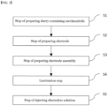
- the method for manufacturing a secondary battery with improved resistance includes: a step of preparing an electrode slurry containing a solvent and an electrode mixture containing succinonitrile (S 1); a step of preparing an electrode by coating the electrode slurry to a current collector and drying the electrode slurry (S2); a step of preparing an electrode assembly by alternately laminating the electrode and a separator (S3); a lamination step of heating and pressing the electrode assembly (S4); and a step of accommodating the laminated electrode assembly in a battery case and injecting an electrolyte solution (S5).
- a content of the succinonitrile is 5 to 40% by weight based on a total weight of the electrode mixture.
- the step (S 1) of preparing the electrode slurry includes a step of uniformly dispersing the succinonitrile in the electrode slurry.
- the step (S2) of preparing the electrode includes: a step of applying the electrode slurry on one or opposite surfaces of the current collector; and a step of drying the electrode to which the electrode slurry has been applied.
- a distribution of the succinonitrile is rearranged so that a content of the succinonitrile of an electrode surface layer far from the current collector becomes greater than a content of the succinonitrile of an electrode inner layer close to the current collector.
- the succinonitrile is positioned on an upper portion or surface of the electrode.
- the upper portion means the end region of the electrode located in a direction far from the current collector, and the surface means one surface contacting the separator, not the current collector.
- the step (S2) of preparing the electrode includes: a step of solidifying liquid succinonitrile by cooling the electrode, to which the electrode slurry has been applied, to a room temperature.
- the lamination step of heating and pressing the electrode assembly (S4) includes: a step of heating the electrode assembly to a temperature of a melting point or more of the succinonitrile.
- a heating temperature of the electrode assembly is 57°C or more, and the electrode assembly is pressed at a pressure of 30kgf/cm or less.
- the succinonitrile acts as a binder between the electrode and the separator.
- the succinonitrile in the electrode is eluted to the electrolyte solution.
- the method for manufacturing a secondary battery according to the present invention does not require a high-pressure process as in the prior art during the lamination process, damage to the separator and electrode can be minimized and process cost can be reduced.
- succinonitrile located on the surface of the electrode serves as an adhesive between the electrode and the separator, adhesive force between the electrode and the separator may be improved.
- the succinonitrile in the electrode is dissolved in the electrolyte solution, there is no resistor on the electrode and the interface between the electrode and the separator. As such, the resistance of the battery may be reduced, which is an advantage.
- FIG. 1 is a schematic diagram showing a conventional secondary battery manufacturing method.
- a binder coating layer 20 is provided on opposite surfaces of the separator 100 in the battery.
- the first electrode 200 and the second electrode 300 were alternately disposed on each side of the binder coating layer 20 to thereby manufacture an electrode assembly.
- a lamination process was performed on opposite sides of the stacked electrode assembly under conditions of high temperature/high pressure as shown in FIG. 1(a) .
- FIG. 1(b) the electrode assembly was accommodated in a battery case, and an electrolyte solution was injected to manufacture a secondary battery 1.
- the binder coating layer 20 was used to increase the adhesive force between the separator 100 and electrodes 200 and 300, but in the manufacture of the secondary battery 1, since the binder coating layer 20 still remains as an element, there is a problem of deteriorating the performance of the battery by binder coating layer 20 acting as an internal resistance.
- styrene-butadiene rubber SBR
- carboxymethyl cellulose CMC
- PVDF polyvinylidene fluoride
- the resistance continually increased due to a high pressure lamination process for improvement of adhesive force between the negative electrode and the separator.
- the present invention relates to a method of manufacturing a secondary battery having improved resistance in order to solve the above problems.
- a method for manufacturing a secondary battery according to the present invention includes:
- succinonitrile is a material mainly used as an electrolyte additive for lithium secondary batteries. Succinonitrile does not interfere with the formation of the SEI (Solid Electrolyte Interface) film of the negative electrode, and does not change the cycle life and capacity of the battery.
- SEI Solid Electrolyte Interface
- succinonitrile exists in the state of a very viscous wax at room temperature, and its melting point is 57°C, so the succinonitrile is present in a liquid state under higher temperature conditions. Therefore, succinonitrile is converted into a wax form when cooled to room temperature after liquefaction, and can serve as an adhesive between the electrode and the separator.
- succinonitrile since the succinonitrile is easily dissolved in water, succinonitrile, which is solid in a room temperature, may be dissolved in water and exist in a liquid state.
- the succinonitrile may be dissolved in a non-aqueous solvent such as a carbonate solvent
- the succinonitrile which exists in the form of an adhesive, may be dissolved and dispersed in the electrolyte solution when injecting the electrolyte solution, thereby acting as an additive to the electrolyte solution.
- the step (S 1) of preparing the electrode slurry includes a step of uniformly dispersing the succinonitrile in the electrode slurry.
- the electrode slurry shows a structure in which an electrode active material, a binder, a conductive material, and succinonitrile are uniformly dispersed in a solvent.
- an aqueous solvent or NMP, a non-aqueous solvent, etc. may be used as the solvent in the electrode slurry according to the present invention.
- Succinonitrile, a binder, and a conductive material may be mixed to prepare a pre-dispersion slurry, and an electrode active material may be added to the pre-dispersion slurry, to thereby manufacture an electrode slurry according to the present invention.
- the succinonitrile may be dissolved in water, to thereby be evenly dispersed in the slurry in a liquid form.
- the manufacturing order or method of the pre-dispersion slurry is not limited to the above example.
- a step (S2) of manufacturing an electrode, in which an electrode mixture layer is formed is performed by applying the electrode slurry, in which the succinonitrile has been uniformly dispersed, which has been prepared in the step (S1) of preparing an electrode slurry, and drying the electrode.
- the step (S2) of preparing the electrode may include: a step of applying the electrode slurry on one or opposite surfaces of the current collector; and a step of drying the electrode to which the electrode slurry has been applied. After the step of applying the electrode slurry to the current collector, the step of drying the electrode may be sequentially performed, or the applying and the drying may be simultaneously performed.
- the electrode slurry coated on the current collector forms an electrode mixture layer as the solvent is removed.
- the content of the succinonitrile may be 0.1 to 5% by weight, preferably 1.5 to 2% by weight, based on the total weight of the electrode mixture.
- the total weight of the electrode mixture refers to the weight of the portion which remains after removing the solvent through drying in the electrode slurry.
- the content and arrangement of the succinonitrile evenly dispersed in the slurry may be changed before and after the drying process.
- the drying temperature is different by sections and is preferably 110°C.
- An electrode slurry layer is formed on the current collector in a state before the slurry is applied on the current collector and is dried.
- succinonitrile is dissolved in a solvent such as water in the electrode slurry layer, the succinonitrile is evenly dispersed in the entire area of the slurry layer.
- the distribution of the succinonitrile in the electrode mixture layer becomes different from the distribution in the electrode slurry.
- the density of the succinonitrile is 0.985g/cc.
- the succinonitrile moves along the evaporation direction of the solvent. Namely, the succinonitrile, which has been uniformly dispersed in the electrode slurry layer applied on the current collector, moves to an electrode slurry layer region, which is far from the current collector, through evaporation of the solvent during the drying process.
- a distribution of the succinonitrile is rearranged so that a content of the succinonitrile of an electrode surface layer far from the current collector becomes greater than a content of the succinonitrile of an electrode inner layer close to the current collector.
- the content of the succinonitrile in the electrode mixture layer may form a concentration gradient toward the electrode surface layer from the electrode inner layer near the current collector.
- the succinonitrile is located on a region far from the current collector, that is, on the upper portion or surface.
- the upper portion means the end region of the electrode located in a direction far from the current collector, and the surface means one surface contacting the separator, not the current collector.
- the description that the succinonitrile is located on the upper portion or surface of the current collector indicates that 90% or more of the succinonitrile included in the electrode mixture layer is located on the upper portion or surface of the electrode mixture layer.
- the step (S2) of preparing the electrode of the present invention may include a step of solidifying liquid succinonitrile by cooling the electrode, to which the electrode slurry has been applied, to a room temperature.
- the succinonitrile which exists inside the electrode mixture layer on the current collector after the drying process, exists in a liquid state due to the heat applied to the electrode mixture layer during the drying process.
- the liquid succinonitrile inside the electrode mixture layer is finally solidified through the process of cooling the electrode to a room temperature after the drying process.
- the succinonitrile As mentioned in the description about the succinonitrile, if the succinonitrile is cooled to a room temperature after being liquefied, it is changed to a was form so that it can serve as a binder if heat is applied during the lamination process.
- a step of preparing an electrode assembly by alternately laminating the electrode and a separator is performed.
- the electrode may be a positive electrode and/or a negative electrode.
- the step of preparing an electrode assembly may be performed in a well know method, and in the present invention, it is preferable to prepare a stack-folding type or stack type electrode assembly.
- the succinonitrile serves as a binder between the electrode and the separator.
- a lamination step (S4) of heating and pressing the manufactured electrode assembly is performed.
- the electrode assembly is heat and pressed at a temperature of a melting point of the succinonitrile or more, specifically 57°C or more, preferably 60°C to 70°C, and the pressure range is 30kgf/cm or less.
- the electrode assembly is heated and pressed at a temperature of 57°C or more, preferably at 60°C to 70°C.
- the succinonitrile which has been in a solid state after the step (S2) of preparing an electrode, is liquefied.
- succinonitrile is evenly dispersed at the interface between the electrode and the separator according to the pressure applied to the electrode assembly at the lamination step.
- the succinonitrile in the electrode acts as a binder between the electrode and the separator.
- the succinonitrile is evenly dispersed at the interface between the electrode and the separator due to the heat and pressure at the lamination step. Liquid succinonitrile may improve the adhesive force between the electrode and the separator due to its sticky characteristic.
- the succinonitrile in a room temperature is solidified in a wax form and serves as a binder for bonding the electrode and the separator.
- the lamination step is performed by pressing the electrode assembly at a pressure of 30 kgf/cm or less, preferably 1 to 10 kgf/cm, and more preferably 1 to 5 kgf/cm.
- a strong pressure is not necessary as the electrode and the separator are bonded using the succinonitrile located on the upper portion or surface of the electrode mixture layer. This not only reduces the process cost, but also prevents physical damage to the separator due to high pressure.
- the electrode assembly to be transferred is passed between a pair of rollers and pressed to bond to each other.
- a heater is connected to a pair of pressing rollers to apply heat to the electrode assembly and pressurize to bond to each other.
- lamination is performed using a pressing roller, but it is also possible to apply press lamination. In this case, it is preferable to use a pressure of 1/10 to 1/5 of the pressure conditions of general press lamination.
- the succinonitrile on the surface of the electrode may improve the adhesive force between the electrode and the separator. This can solve the problem of a damage to a separator which may occur due to a high temperature and high pressure lamination process and may solve the problem of an increase of a resistance of the positive electrode of a battery. Further, this may reduce the binder content inside the binder layer which exists in the surface of the separator used for the electrode assembly. Further, since a high temperature and high pressure lamination process is not required, the effect of reduction of process costs can be expected.
- step (S5) of accommodating the laminated electrode assembly in a battery case and injecting an electrolyte solution is performed.
- step (S5) of accommodating the laminated electrode assembly in a battery case and injecting an electrolyte solution as the electrolyte solution is injected, the succinonitrile in the electrode is eluted to the electrolyte solution and is removed from the interface between the electrode and the separator. Thereafter, since the succinonitrile eluted to the electrolyte solution acts as an additive to the electrolyte solution, it is possible to prevent the succinonitrile from acting as a resistance component in the electrode mixture layer.
- FIG. 3 is a schematic diagram showing a method of manufacturing a secondary battery according to one embodiment of the present invention.
- FIG. 3 illustrates only a negative electrode and a separator in an electrode assembly and omits a positive electrode portion. Further, it is also possible to apply the manufacturing method according to the present invention for the positive electrode.
- FIG. 3(a) shows a state that a negative electrode slurry layer 220, in which succinonitrile 10 had been uniformly dispersed, has been applied on the negative electrode current collector 210.
- the solvent is evaporated, and the slurry layer becomes a negative electrode mixture layer, and at the same time, the succinonitrile 10 is arranged on the upper portion or surface of the negative electrode mixture layer.
- the separator 100 is laminated on the dried negative electrode 200, and in FIG. 3(d) , the succinonitrile acts as a binder for bonding the negative electrode and the separator through a lamination process.
- FIG. 3(b) shows a state that a negative electrode slurry layer 220, in which succinonitrile 10 had been uniformly dispersed, has been applied on the negative electrode current collector 210.
- the solvent is evaporated, and the slurry layer becomes a negative electrode mixture layer, and at the same time, the succinonitrile 10 is arranged on the upper portion or surface of the
- succinonitrile of the present invention acts as an adhesive means between the electrode and the separator, there is an advantage in that it is easy to adhere even in a lamination process of a lower temperature and pressure than the conventional one.
- succinonitrile is dissolved in the electrolyte injection process, which is the rear end of the battery manufacturing process, and does not remain within the interface anymore, the resistance of the battery can be minimized, thereby exhibiting an effect of preventing performance degradation of the battery.
- the electrode used in the present invention is an electrode for a lithium secondary battery.
- the lithium secondary battery includes, for example, an electrode assembly including a positive electrode, a negative electrode, and a separator interposed between the positive electrode and the negative electrode; a non-aqueous electrolyte impregnating the electrode assembly; and a battery case containing the electrode assembly and the non-aqueous electrolyte.
- the positive electrode has a structure in which a positive electrode mixture layer is stacked on one or opposite sides of a positive electrode current collector.
- the positive electrode active materials may each independently be a lithium-containing oxide, and may be the same or different.
- a lithium-containing transition metal oxide may be used as the lithium-containing oxide.
- the positive electrode mixture layer includes a conductive material and a binder polymer in addition to the positive electrode active material, and if necessary, may further include a positive electrode additive commonly used in the art.
- the positive electrode active material may be a lithium-containing oxide, and may be the same or different.
- a lithium-containing transition metal oxide may be used as the lithium-containing oxide.
- the lithium-containing transition metal oxide may be coated with a metal such as aluminum (Al) or a metal oxide.
- a metal such as aluminum (Al) or a metal oxide.
- one or more of sulfide, selenide, and halide may be used.
- the current collector used for the positive electrode is a metal having high conductivity, and any metal which the positive electrode active material slurry may be easily attached to and which is not reactive in the voltage range of the secondary battery can be used.
- the current collector for the positive electrode include aluminum, nickel, or a foil manufactured by a combination thereof.
- the current collector for the positive electrode is formed of metal components described above, and includes a metal plate having a through hole in the thickness direction, and an ion conductive porous reinforcing material filled in the through hole of the metal plate.
- the negative electrode may further include a negative electrode mixture layer, and may include a carbon material, lithium metal, silicon, or tin.
- a carbon material is used as the negative electrode active material, opposite low crystalline carbon and high crystalline carbon may be used.
- Representative examples of low crystalline carbon include soft carbon and hard carbon.
- Representative examples of high crystalline carbon include natural graphite, kish graphite, pyrolytic carbon, mesophase pitch based carbon fiber, mesocarbon microbeads, mesophase pitches, and high-temperature calcined carbons such as petroleum or coal tar pitch derived cokes.
- Non-limiting examples of the current collector used for the negative electrode include copper, gold, nickel, or a foil manufactured by a copper alloy or a combination thereof.
- the current collector may be used by stacking substrates made of the above materials.
- the current collector for the negative electrode is formed of metal components described above, and includes a metal plate having a through hole in the thickness direction, and an ion conductive porous reinforcing material filled in the through hole of the metal plate.
- the negative electrode may include a conductive material and a binder commonly used in the art.
- the separator may be made of any porous substrate used in a lithium secondary battery, and for example, a polyolefin-based porous membrane or a nonwoven fabric may be used, but the present invention is not particularly limited thereto.
- the polyolefin-based porous membrane include polyethylene such as high density polyethylene, linear low density polyethylene, low density polyethylene, ultra high molecular weight polyethylene, and a membrane in which polyolefin-based polymers, such as polypropylene, polybutylene, and polypentene, are each formed alone or in a mixture thereof.
- a non-aqueous electrolyte containing a non-aqueous electrolyte solution may be used as the electrolyte solution.
- the non-aqueous electrolyte include N-methyl-2-pyrrolidinone, propylene carbonate, ethylene carbonate, butylenecarbonate, dimethyl carbonate, diethyl carbonate, gamma-Butyrolactone, 1,2-dimethoxyethane, tetrahydroxyfuran, 2-methyltetrahydrofuran, dimethylsulfoxide, 1,3-dioxolane, formamide, dimethylformamide, dioxolane, acetonitrile, nitromethane, methyl formate, methyl acetate, phosphoric acid triester, trimethoxymethane, dioxolane derivatives, sulfolane, methyl sulfolane, 1,3-dimethyl-2-imidazolidinone, propylene carbonate derivatives, tetrahydrofuran derivative
- the present invention provides a vehicle or large-capacity energy storage device including the secondary battery described above.
- the vehicle is a hybrid or electric vehicle.
- a non-aqueous electrolyte solution as a solvent was added to a positive electrode mixture containing 2 wt% of succinonitrile (SN), 2.5 wt% of PVDF (binder), 2.5 wt% of carbon black (conductive agent), and 93 wt% of LiCoO 2 as the positive electrode active material, to thereby prepare a positive electrode slurry, which was then applied on opposite surfaces of the current collector, and dried and rolled to thereby manufacture a positive electrode.
- SN succinonitrile
- PVDF binder
- carbon black conductive agent
- a non-aqueous electrolyte solution as a solvent was added to a negative electrode mixture containing 2 wt% of succinonitrile (SN), 1.5 wt% of SBR (binder), 1.0 wt% of CMC (binder), 2.5 wt% of carbon black (conductive agent), and 93 wt% of graphite as the negative electrode active material, to thereby prepare a negative electrode slurry, which was then applied on opposite surfaces of the current collector, and dried and rolled to thereby manufacture a negative electrode.
- SN succinonitrile
- SBR synBR
- CMC binder
- conductive agent conductive agent
- a porous polyethylene containing a coating layer containing 15 wt% PVDF binder was used as the separator.
- a positive electrode was placed on one side of the separator, and a negative electrode was placed on the opposite side, and then laminated to manufacture an electrode assembly. At this time, the electrode assembly was roll-laminated at the condition of 80°C and 5 kgf/cm.
- the laminated electrode assembly was accommodated in a pouch-type battery case, and an electrolyte solution was injected to manufacture a secondary battery.
- Example 2 When SN content in the electrode mixture is set to 3% in Example 1
- Example 3 When SN content in the electrode mixture is set to 4% in Example 1
- Example 4 When SN content in the electrode mixture is set to 5% in Example 1
- Example 5 In Example 1, SN is not contained in the positive electrode mixture, and SN is contained only in the negative electrode mixture by 2%.
- Example 6 Change roll lamination pressure to 10 kgf/cm in Example 5
- Example 7 Change roll lamination pressure to 30 kgf/cm in Example 5
- Comparative example 4 in Example 5, SN is not contained in the positive electrode mixture, and SN is contained only in the negative electrode mixture by 0.05%.
- the adhesive force was measured while detaching the separator from the negative electrode at a rate of 20mm/min at the angel of 90 degrees.
- the adhesive force was 200 gf/20 mm
- the electrode was bent.
- the adhesive force was 200 gf/ 20 mm or more
- the adhesive force between the separator and the electrode is excessively strong, so that it is not possible to detach the separator from the electrode when measuring the adhesive force, thereby showing a phenomenon that the electrode is bent. In such a case, the resistance is generally high due to excessive lamination conditions.
- the succinonitrile which existed in the slurry in the drying step of the electrode manufacturing process, is moved to the upper portion of the electrode or the electrode surface layer, so that the succinonitrile is rearranged in the electrode.
- the succinonitrile of a low density which evenly existed in the electrode slurry, are rearranged from the electrode inner layer close to the current collector to an electrode surface layer far from the current collector through the electrode drying process, the succinonitrile is finally positioned on the upper portion or surface of the electrode.
- the succinonitrile which is positioned on the surface of the electrode, is liquefied by the lamination condition, thereby acting as a binder for bonding the separator and the electrode. Thereafter, in the condition after the lamination process, the succinonitrile is solidified and improves the adhesive force between the separator and the electrode. According to Table 1, in the example of the present invention, as an appropriate amount of succinonitrile is used, the adhesive force between the electrode and the separator is improved.
- Examples 1 to 4 are different from Comparative examples 1 and 2 only in the SN content in the electrode of the same condition.
- the adhesive force of the negative electrode/separator of Examples 1 to 4 is superior to that of Comparative example 1 or 2, and the cyclic characteristics of Examples 1 to 4 are also superior to those of Comparative example 1 or 2.
- Comparative example 1 if too small amount of SN is applied to the positive electrode and the negative electrode, the adhesive force is not sufficiently secured, and the capacity was low compared to 2.0C discharge. In Comparative example 2, if too much succinonitrile is applied, the adhesive force is good, but the capacity also low, compared to 2.0C discharge. Since the viscosity of the succinonitrile is high, when too much succinonitrile is applied, the ion conductivity becomes low, thereby increasing the resistance.
- Example 5 and Comparative example 4 are the same except for the SN content in the negative electrode mixture.
- the adhesive force between the negative electrode and the separator becomes too low.
- 2.0C discharge capacity of Comparative example 4 was lower than that of Example 4.
- Comparative example 1 since the succinonitrile content was low, the adhesive force between the electrode and the separator was not improved.
- Comparative example 2 since the succinonitrile content was high, the succinonitrile, which remained on the surface of the electrode and the separator, acted as a resistance, thereby deteriorating cycle characteristics. Since the lamination pressure of Comparative example 3 is greater than that of Examples 5 to 7, the binder between the positive electrode and the separator melts and acts as a resistance, and as a damage to the separator occurs, the electrode is bent and at the same time, cycle characteristics are deteriorated. Since the SN content of Comparative example 4 is smaller than that of Example 5, sufficient adhesive force between the electrode and the separator was not secured, and the cycle characteristics were not improved.
Landscapes
- Chemical & Material Sciences (AREA)
- Chemical Kinetics & Catalysis (AREA)
- Electrochemistry (AREA)
- General Chemical & Material Sciences (AREA)
- Engineering & Computer Science (AREA)
- Manufacturing & Machinery (AREA)
- Inorganic Chemistry (AREA)
- Materials Engineering (AREA)
- Physics & Mathematics (AREA)
- Condensed Matter Physics & Semiconductors (AREA)
- General Physics & Mathematics (AREA)
- Secondary Cells (AREA)
- Battery Electrode And Active Subsutance (AREA)
Description
- This application claims the benefit of priority based on
Korean Patent Application No. 10-2020-0054039, filed on May 6, 2020 - The present invention relates to a method for manufacturing a secondary battery with an improved resistance by using an electrode slurry containing succinonitrile when manufacturing a lithium secondary battery.
- With the increase in technology development and demand for mobile devices, the demand for secondary batteries is also rapidly increasing. Among them, lithium secondary batteries are widely used as an energy source for various electronic products as well as various mobile devices because of their high energy density and high operating voltage and excellent storage and lifetime characteristics.
- Secondary batteries are classified into coin-type batteries, cylindrical batteries, prismatic batteries, and pouch-type batteries according to the shape of the battery case. In a secondary battery, an electrode assembly mounted inside a battery case is a power generating element capable of charging and discharging having a stacked structure of electrodes and separators.
- The electrode assembly may be classified into a jellyroll type which is wound with a separator interposed between sheet-type positive electrode and negative electrode coated with the active material, a stack type in which multiple positive electrodes and negative electrodes are sequentially stacked with a separator interposed therebetween, and a stack/folding type in which stack-type unit cells are wound with a long separation film.
- Among them, in the case of a battery having a stack type or a stack/folding type structure, a lamination process of bonding an electrode and a separator during battery manufacturing is essential. The lamination process is a process of attaching an electrode and a separator, and if the electrode and the separator fall apart, the yield and processability are very poor when assembling the battery. In addition, it is impossible to assemble a stacked or stacked/folded battery without a lamination process.
- Conventionally, for the lamination process, a binder layer was formed on the surface of the separator, and thereafter, the electrode and the separator were bonded under high temperature and high pressure conditions. However, during this process, damage to the separator occurs, and the binder used as an adhesive remains melted and acts as a resistance in the battery, thereby deteriorating battery performance.
- In particular, in the case of the negative electrode, since the components of the binder used in the electrode are different from the components of the separator binder, they are not bonded well even after the lamination process. Hence, a greater pressure was necessary at the time of lamination. At this time, the resistance of the positive electrode increased due to a strong pressure.
- Specifically, in the lamination process, the electrode is laminated in the order of positive electrode/ separator negative electrode, and then heat and pressure are applied to the laminated electrode (lamination cell). As such, the same heat and pressure are applied to the positive electrode and the negative electrode. In the case of the positive electrode, the binder material in the electrode is PVDF, which is the same as the binder used in the separator. As such, the adhesive force is sufficiently secured at a low temperature/pressure. However, in the case of the negative electrode, CMC and SBR are used as the binder, and thus the adhesive force with the separator is low. Therefore, in order to secure the adhesive force of the negative electrode, application of a high temperature and a high pressure is essential, and thus as the lamination process is excessively performed for the positive electrode, the binder at the interface between the positive electrode and the separator melts, thereby acting as a resistance on the interface. Further, as the pores of the separator between the positive electrode and the negative electrode are reduced due to an excessive pressure, the resistance increases.
- Therefore, there is a need for a method for manufacturing a secondary battery capable of preventing a damage of a separator and an increase of a resistance of a positive electrode due to a high temperature and a high pressure during a lamination process.
-
KR 2006 0045320 A WO 2005/078832 A1 disclose an electrode comprising succinonitrile dispersed in the electrode. - The present invention has been created to solve the above problems and relates to a method of manufacturing a secondary battery which may improve an adhesive force between a negative electrode and a separator during a lamination process, minimize damage to a separator and a positive electrode by a high pressure, and improve a resistance in a battery.
- The method for manufacturing a secondary battery with improved resistance according to the present invention is defined in the appended set of claims, the method includes:
a step of preparing an electrode slurry containing a solvent and an electrode mixture containing succinonitrile (S 1); a step of preparing an electrode by coating the electrode slurry to a current collector and drying the electrode slurry (S2); a step of preparing an electrode assembly by alternately laminating the electrode and a separator (S3); a lamination step of heating and pressing the electrode assembly (S4); and a step of accommodating the laminated electrode assembly in a battery case and injecting an electrolyte solution (S5). - In one example, a content of the succinonitrile is 5 to 40% by weight based on a total weight of the electrode mixture.
- In another example, the step (S 1) of preparing the electrode slurry includes a step of uniformly dispersing the succinonitrile in the electrode slurry.
- In one example, the step (S2) of preparing the electrode includes: a step of applying the electrode slurry on one or opposite surfaces of the current collector; and a step of drying the electrode to which the electrode slurry has been applied.
- In a specific example, in the step of drying the electrode slurry, a distribution of the succinonitrile is rearranged so that a content of the succinonitrile of an electrode surface layer far from the current collector becomes greater than a content of the succinonitrile of an electrode inner layer close to the current collector.
- Further, in the step of drying the electrode slurry, the succinonitrile is positioned on an upper portion or surface of the electrode. The upper portion means the end region of the electrode located in a direction far from the current collector, and the surface means one surface contacting the separator, not the current collector.
- In another example, the step (S2) of preparing the electrode includes: a step of solidifying liquid succinonitrile by cooling the electrode, to which the electrode slurry has been applied, to a room temperature.
- In one example, the lamination step of heating and pressing the electrode assembly (S4) includes: a step of heating the electrode assembly to a temperature of a melting point or more of the succinonitrile.
- Specifically, a heating temperature of the electrode assembly is 57°C or more, and the electrode assembly is pressed at a pressure of 30kgf/cm or less.
- At this time, the succinonitrile acts as a binder between the electrode and the separator.
- In another example, in the step of accommodating the laminated electrode assembly in a battery case and injecting an electrolyte solution (S5), the succinonitrile in the electrode is eluted to the electrolyte solution.
- Since the method for manufacturing a secondary battery according to the present invention does not require a high-pressure process as in the prior art during the lamination process, damage to the separator and electrode can be minimized and process cost can be reduced.
- Further, since succinonitrile located on the surface of the electrode serves as an adhesive between the electrode and the separator, adhesive force between the electrode and the separator may be improved.
- Further, since the succinonitrile in the electrode is dissolved in the electrolyte solution, there is no resistor on the electrode and the interface between the electrode and the separator. As such, the resistance of the battery may be reduced, which is an advantage.
-
-
FIG. 1 is a schematic diagram showing a conventional secondary battery manufacturing method. -
FIG. 2 is a flowchart illustrating a method of manufacturing a secondary battery according to the present invention. -
FIG. 3 is a schematic diagram showing a method of manufacturing a secondary battery according to one embodiment of the present invention. - Hereinafter, the present invention will be described in detail with reference to the drawings. The terms and words used in the present specification and claims should not be construed as limited to ordinary or dictionary terms and the inventor may properly define the concept of the terms in order to best describe its invention. The terms and words should be construed as meaning and concept consistent with the technical idea of the present invention.
-
FIG. 1 is a schematic diagram showing a conventional secondary battery manufacturing method. - Referring to
FIG. 1 , in a battery constituting an existing secondary battery, abinder coating layer 20 is provided on opposite surfaces of theseparator 100 in the battery. Thefirst electrode 200 and thesecond electrode 300 were alternately disposed on each side of thebinder coating layer 20 to thereby manufacture an electrode assembly. Thereafter, a lamination process was performed on opposite sides of the stacked electrode assembly under conditions of high temperature/high pressure as shown inFIG. 1(a) .Thereafter, as shown inFIG. 1(b) , the electrode assembly was accommodated in a battery case, and an electrolyte solution was injected to manufacture asecondary battery 1. - In the conventional method as described above, the
binder coating layer 20 was used to increase the adhesive force between theseparator 100 andelectrodes secondary battery 1, since thebinder coating layer 20 still remains as an element, there is a problem of deteriorating the performance of the battery bybinder coating layer 20 acting as an internal resistance. - Further, a mixture of styrene-butadiene rubber (SBR), and carboxymethyl cellulose (CMC) is used as the negative electrode binder, and polyvinylidene fluoride (PVDF) is used as the positive electrode binder and the binder of the binder coating layer on the separator.
- In a general negative electrode, since the components of the binder in the negative electrode are different from the components of the binder of the
binder coating layer 20 on theseparator 100, adhesive force decreased during the lamination process. As such, stronger pressure was required during the lamination process. - In the case of a positive electrode same as or similar to the binder components of the separator, the resistance continually increased due to a high pressure lamination process for improvement of adhesive force between the negative electrode and the separator.
- The present invention relates to a method of manufacturing a secondary battery having improved resistance in order to solve the above problems.
- Referring to
FIG. 2 , a method for manufacturing a secondary battery according to the present invention includes: - a step of preparing an electrode slurry containing a solvent and an electrode mixture containing succinonitrile (S 1); a step of preparing an electrode by coating the electrode slurry to a current collector and drying the electrode slurry (S2); a step of preparing an electrode assembly by alternately laminating the electrode and a separator (S3);
- a lamination step of heating and pressing the electrode assembly (S4); and a step of accommodating the laminated electrode assembly in a battery case and injecting an electrolyte solution (S5).
- First, succinonitrile (SN) will be described. Succinonitrile is a material mainly used as an electrolyte additive for lithium secondary batteries. Succinonitrile does not interfere with the formation of the SEI (Solid Electrolyte Interface) film of the negative electrode, and does not change the cycle life and capacity of the battery.
- In addition, succinonitrile exists in the state of a very viscous wax at room temperature, and its melting point is 57°C, so the succinonitrile is present in a liquid state under higher temperature conditions. Therefore, succinonitrile is converted into a wax form when cooled to room temperature after liquefaction, and can serve as an adhesive between the electrode and the separator.
- Further, since the succinonitrile is easily dissolved in water, succinonitrile, which is solid in a room temperature, may be dissolved in water and exist in a liquid state.
- Further, since the succinonitrile may be dissolved in a non-aqueous solvent such as a carbonate solvent, the succinonitrile, which exists in the form of an adhesive, may be dissolved and dispersed in the electrolyte solution when injecting the electrolyte solution, thereby acting as an additive to the electrolyte solution.
- Hereinafter, a secondary battery manufacturing method of the present invention will be described in detail by steps.
- First, the step (S 1) of preparing the electrode slurry includes a step of uniformly dispersing the succinonitrile in the electrode slurry.
- As such, the electrode slurry shows a structure in which an electrode active material, a binder, a conductive material, and succinonitrile are uniformly dispersed in a solvent. Specifically, an aqueous solvent or NMP, a non-aqueous solvent, etc. may be used as the solvent in the electrode slurry according to the present invention. Succinonitrile, a binder, and a conductive material may be mixed to prepare a pre-dispersion slurry, and an electrode active material may be added to the pre-dispersion slurry, to thereby manufacture an electrode slurry according to the present invention. At this time, the succinonitrile may be dissolved in water, to thereby be evenly dispersed in the slurry in a liquid form. The manufacturing order or method of the pre-dispersion slurry is not limited to the above example.
- Second, a step (S2) of manufacturing an electrode, in which an electrode mixture layer is formed, is performed by applying the electrode slurry, in which the succinonitrile has been uniformly dispersed, which has been prepared in the step (S1) of preparing an electrode slurry, and drying the electrode.
- Specifically, the step (S2) of preparing the electrode may include: a step of applying the electrode slurry on one or opposite surfaces of the current collector; and a step of drying the electrode to which the electrode slurry has been applied. After the step of applying the electrode slurry to the current collector, the step of drying the electrode may be sequentially performed, or the applying and the drying may be simultaneously performed.
- In the above process of drying the electrode, the electrode slurry coated on the current collector forms an electrode mixture layer as the solvent is removed. At this time, the content of the succinonitrile may be 0.1 to 5% by weight, preferably 1.5 to 2% by weight, based on the total weight of the electrode mixture. At this time, the total weight of the electrode mixture refers to the weight of the portion which remains after removing the solvent through drying in the electrode slurry. When the content of the succinonitrile is in the above range, the electrode may be stably bonded to the separator, and the resistance of the battery can be maintained low. If the content of the succinonitrile is less than 0.1% by weight, the adhesive force between the electrode and the separator can be reduced, and if the content of the succinonitrile exceeds 5% by weight, the resistance of the battery can be increased.
- Further, in the step of applying and drying the electrode slurry on the current collector, the content and arrangement of the succinonitrile evenly dispersed in the slurry may be changed before and after the drying process. The drying temperature is different by sections and is preferably 110°C.
- An electrode slurry layer is formed on the current collector in a state before the slurry is applied on the current collector and is dried. In this case, succinonitrile is dissolved in a solvent such as water in the electrode slurry layer, the succinonitrile is evenly dispersed in the entire area of the slurry layer.
- However, as the solvent in the electrode slurry is vaporized in the drying process, the distribution of the succinonitrile in the electrode mixture layer becomes different from the distribution in the electrode slurry.
- Generally the density of the succinonitrile is 0.985g/cc. As the solvent in the electrode slurry layer is evaporated, due to a low density, the succinonitrile moves along the evaporation direction of the solvent. Namely, the succinonitrile, which has been uniformly dispersed in the electrode slurry layer applied on the current collector, moves to an electrode slurry layer region, which is far from the current collector, through evaporation of the solvent during the drying process.
- As such, in the step of drying the electrode slurry applied to the current collector, a distribution of the succinonitrile is rearranged so that a content of the succinonitrile of an electrode surface layer far from the current collector becomes greater than a content of the succinonitrile of an electrode inner layer close to the current collector. Specifically, the content of the succinonitrile in the electrode mixture layer may form a concentration gradient toward the electrode surface layer from the electrode inner layer near the current collector.
- In addition, the succinonitrile is located on a region far from the current collector, that is, on the upper portion or surface. Herein, the upper portion means the end region of the electrode located in a direction far from the current collector, and the surface means one surface contacting the separator, not the current collector. Further, the description that the succinonitrile is located on the upper portion or surface of the current collector indicates that 90% or more of the succinonitrile included in the electrode mixture layer is located on the upper portion or surface of the electrode mixture layer.
- Meanwhile, the step (S2) of preparing the electrode of the present invention may include a step of solidifying liquid succinonitrile by cooling the electrode, to which the electrode slurry has been applied, to a room temperature. Specifically, the succinonitrile, which exists inside the electrode mixture layer on the current collector after the drying process, exists in a liquid state due to the heat applied to the electrode mixture layer during the drying process. The liquid succinonitrile inside the electrode mixture layer is finally solidified through the process of cooling the electrode to a room temperature after the drying process. As mentioned in the description about the succinonitrile, if the succinonitrile is cooled to a room temperature after being liquefied, it is changed to a was form so that it can serve as a binder if heat is applied during the lamination process.
- After performing the step (S2) of preparing an electrode, a step of preparing an electrode assembly by alternately laminating the electrode and a separator (S3) is performed. In the present invention, the electrode may be a positive electrode and/or a negative electrode. The step of preparing an electrode assembly may be performed in a well know method, and in the present invention, it is preferable to prepare a stack-folding type or stack type electrode assembly. As will be described later, the succinonitrile serves as a binder between the electrode and the separator.
- After performing the step (S3) of manufacturing the electrode assembly, a lamination step (S4) of heating and pressing the manufactured electrode assembly is performed.
- Specifically, in the lamination step of the present invention, the electrode assembly is heat and pressed at a temperature of a melting point of the succinonitrile or more, specifically 57°C or more, preferably 60°C to 70°C, and the pressure range is 30kgf/cm or less.
- In the conventional lamination process, a pressure of 10 to 50 kgf/cm is applied under a temperature condition of 70 to 100°C.Through this, the electrode and the separator are strongly attached, and the thickness of the separator fabric is generally reduced by about 10% through the lamination process as described above.
- However, in the lamination step of the present invention, the electrode assembly is heated and pressed at a temperature of 57°C or more, preferably at 60°C to 70°C. As the electrode assembly is laminated at the temperature, the succinonitrile, which has been in a solid state after the step (S2) of preparing an electrode, is liquefied. As such, liquefied succinonitrile is evenly dispersed at the interface between the electrode and the separator according to the pressure applied to the electrode assembly at the lamination step. Further, since the lamination process is performed at a relatively low temperature through the above temperature conditions unlike the conventional lamination process, not only the process cost can be reduced, but also a damage such as shrinkage of the separator due to a high temperature can be prevented.
- Further, the succinonitrile in the electrode acts as a binder between the electrode and the separator. Specifically, the succinonitrile is evenly dispersed at the interface between the electrode and the separator due to the heat and pressure at the lamination step. Liquid succinonitrile may improve the adhesive force between the electrode and the separator due to its sticky characteristic. Thereafter, after the lamination process, the succinonitrile in a room temperature is solidified in a wax form and serves as a binder for bonding the electrode and the separator.
- Further, the lamination step is performed by pressing the electrode assembly at a pressure of 30 kgf/cm or less, preferably 1 to 10 kgf/cm, and more preferably 1 to 5 kgf/cm. In the present invention, as the electrode and the separator are bonded using the succinonitrile located on the upper portion or surface of the electrode mixture layer, a strong pressure is not necessary. This not only reduces the process cost, but also prevents physical damage to the separator due to high pressure.
- In the lamination process, the electrode assembly to be transferred is passed between a pair of rollers and pressed to bond to each other. Specifically, in the lamination process, a heater is connected to a pair of pressing rollers to apply heat to the electrode assembly and pressurize to bond to each other.
- In the present invention, lamination is performed using a pressing roller, but it is also possible to apply press lamination. In this case, it is preferable to use a pressure of 1/10 to 1/5 of the pressure conditions of general press lamination.
- Likewise, the succinonitrile on the surface of the electrode may improve the adhesive force between the electrode and the separator. This can solve the problem of a damage to a separator which may occur due to a high temperature and high pressure lamination process and may solve the problem of an increase of a resistance of the positive electrode of a battery. Further, this may reduce the binder content inside the binder layer which exists in the surface of the separator used for the electrode assembly. Further, since a high temperature and high pressure lamination process is not required, the effect of reduction of process costs can be expected.
- Finally, the step (S5) of accommodating the laminated electrode assembly in a battery case and injecting an electrolyte solution is performed.
- Specifically, in the step (S5) of accommodating the laminated electrode assembly in a battery case and injecting an electrolyte solution, as the electrolyte solution is injected, the succinonitrile in the electrode is eluted to the electrolyte solution and is removed from the interface between the electrode and the separator. Thereafter, since the succinonitrile eluted to the electrolyte solution acts as an additive to the electrolyte solution, it is possible to prevent the succinonitrile from acting as a resistance component in the electrode mixture layer.
-
FIG. 3 is a schematic diagram showing a method of manufacturing a secondary battery according to one embodiment of the present invention.FIG. 3 illustrates only a negative electrode and a separator in an electrode assembly and omits a positive electrode portion. Further, it is also possible to apply the manufacturing method according to the present invention for the positive electrode. -
FIG. 3(a) shows a state that a negativeelectrode slurry layer 220, in which succinonitrile 10 had been uniformly dispersed, has been applied on the negative electrodecurrent collector 210. Thereafter, inFIG. 3(b) , as dried in a high temperature, the solvent is evaporated, and the slurry layer becomes a negative electrode mixture layer, and at the same time, thesuccinonitrile 10 is arranged on the upper portion or surface of the negative electrode mixture layer. InFIG. 3(c) , theseparator 100 is laminated on the driednegative electrode 200, and inFIG. 3(d) , the succinonitrile acts as a binder for bonding the negative electrode and the separator through a lamination process. Thereafter, inFIG. 3(e) , as an electrode assembly including a negative electrode and a separator is accommodated in a battery case and an electrolyte solution is injected thereto, the succinonitrile is dissolved in an electrolyte solution solvent, and thus the succinonitrile does not exist in the electrode assembly. - In summary, since succinonitrile of the present invention acts as an adhesive means between the electrode and the separator, there is an advantage in that it is easy to adhere even in a lamination process of a lower temperature and pressure than the conventional one. In addition, since succinonitrile is dissolved in the electrolyte injection process, which is the rear end of the battery manufacturing process, and does not remain within the interface anymore, the resistance of the battery can be minimized, thereby exhibiting an effect of preventing performance degradation of the battery.
- Hereinafter, the secondary battery used in the present invention will be described.
- The electrode used in the present invention is an electrode for a lithium secondary battery. The lithium secondary battery includes, for example, an electrode assembly including a positive electrode, a negative electrode, and a separator interposed between the positive electrode and the negative electrode; a non-aqueous electrolyte impregnating the electrode assembly; and a battery case containing the electrode assembly and the non-aqueous electrolyte.
- The positive electrode has a structure in which a positive electrode mixture layer is stacked on one or opposite sides of a positive electrode current collector. The positive electrode active materials may each independently be a lithium-containing oxide, and may be the same or different. A lithium-containing transition metal oxide may be used as the lithium-containing oxide. In one example, the positive electrode mixture layer includes a conductive material and a binder polymer in addition to the positive electrode active material, and if necessary, may further include a positive electrode additive commonly used in the art.
- The positive electrode active material may be a lithium-containing oxide, and may be the same or different. A lithium-containing transition metal oxide may be used as the lithium-containing oxide.
- For example, the lithium-containing transition metal oxide may be any one or a mixture of two or more selected from the group consisting of LixCoO2(0.5<x<1.3), LixNiO2(0.5<x<1.3), LixMnO2(0.5<x<1.3), LixMn2O4(0.5<x<1.3), Lix(NiaCobMnc)O2(0.5<x<1.3, 0<a<1, 0<b<1, 0<c<1, a+b+c=1), LixNi1-yCoyO2(0.5<x<1.3, 0<y<1), LixCo1-yMnyO2(0.5<x<1.3, 0≤y<1), LixNi1-yMnyO2(0.5<x<1.3, 0≤y<1), Lix(NiaCobMnc)O4(0.5<x<1.3, 0<a<2, 0<b<2, 0<c<2, a+b+c=2), LixMn2-zNizO4(0.5<x<1.3, 0<z<2), LixMn2-zCozO4(0.5<x<1.3, 0<z<2), LixCoPO4(0.5<x<1.3) and LixFePO4(0.5<x<1.3). In addition, the lithium-containing transition metal oxide may be coated with a metal such as aluminum (Al) or a metal oxide. Further, in addition to the lithium-containing transition metal oxide, one or more of sulfide, selenide, and halide may be used.
- The current collector used for the positive electrode is a metal having high conductivity, and any metal which the positive electrode active material slurry may be easily attached to and which is not reactive in the voltage range of the secondary battery can be used. Specifically, non-limiting examples of the current collector for the positive electrode include aluminum, nickel, or a foil manufactured by a combination thereof. Specifically, the current collector for the positive electrode is formed of metal components described above, and includes a metal plate having a through hole in the thickness direction, and an ion conductive porous reinforcing material filled in the through hole of the metal plate.
- The negative electrode may further include a negative electrode mixture layer, and may include a carbon material, lithium metal, silicon, or tin.When a carbon material is used as the negative electrode active material, opposite low crystalline carbon and high crystalline carbon may be used. Representative examples of low crystalline carbon include soft carbon and hard carbon. Representative examples of high crystalline carbon include natural graphite, kish graphite, pyrolytic carbon, mesophase pitch based carbon fiber, mesocarbon microbeads, mesophase pitches, and high-temperature calcined carbons such as petroleum or coal tar pitch derived cokes.
- Non-limiting examples of the current collector used for the negative electrode include copper, gold, nickel, or a foil manufactured by a copper alloy or a combination thereof. In addition, the current collector may be used by stacking substrates made of the above materials. Specifically, the current collector for the negative electrode is formed of metal components described above, and includes a metal plate having a through hole in the thickness direction, and an ion conductive porous reinforcing material filled in the through hole of the metal plate.
- In addition, the negative electrode may include a conductive material and a binder commonly used in the art.
- The separator may be made of any porous substrate used in a lithium secondary battery, and for example, a polyolefin-based porous membrane or a nonwoven fabric may be used, but the present invention is not particularly limited thereto. Examples of the polyolefin-based porous membrane include polyethylene such as high density polyethylene, linear low density polyethylene, low density polyethylene, ultra high molecular weight polyethylene, and a membrane in which polyolefin-based polymers, such as polypropylene, polybutylene, and polypentene, are each formed alone or in a mixture thereof.
- A non-aqueous electrolyte containing a non-aqueous electrolyte solution may be used as the electrolyte solution. Examples of the non-aqueous electrolyte include N-methyl-2-pyrrolidinone, propylene carbonate, ethylene carbonate, butylenecarbonate, dimethyl carbonate, diethyl carbonate, gamma-Butyrolactone, 1,2-dimethoxyethane, tetrahydroxyfuran, 2-methyltetrahydrofuran, dimethylsulfoxide, 1,3-dioxolane, formamide, dimethylformamide, dioxolane, acetonitrile, nitromethane, methyl formate, methyl acetate, phosphoric acid triester, trimethoxymethane, dioxolane derivatives, sulfolane, methyl sulfolane, 1,3-dimethyl-2-imidazolidinone, propylene carbonate derivatives, tetrahydrofuran derivatives, ethers, methyl pyrophosphate, ethyl propionate, etc.However, it is not particularly limited thereto, and a number of electrolyte components commonly used in the field of lithium secondary batteries may be added or subtracted within an appropriate range.
- In addition, the present invention provides a vehicle or large-capacity energy storage device including the secondary battery described above. In a specific example, the vehicle is a hybrid or electric vehicle.
- Hereinafter, the present invention will be described in more detail through examples. However, the embodiments described in the specification and the configurations described in the drawings are only the most preferred embodiments of the present invention.
- A non-aqueous electrolyte solution as a solvent was added to a positive electrode mixture containing 2 wt% of succinonitrile (SN), 2.5 wt% of PVDF (binder), 2.5 wt% of carbon black (conductive agent), and 93 wt% of LiCoO2 as the positive electrode active material, to thereby prepare a positive electrode slurry, which was then applied on opposite surfaces of the current collector, and dried and rolled to thereby manufacture a positive electrode.
- A non-aqueous electrolyte solution as a solvent was added to a negative electrode mixture containing 2 wt% of succinonitrile (SN), 1.5 wt% of SBR (binder), 1.0 wt% of CMC (binder), 2.5 wt% of carbon black (conductive agent), and 93 wt% of graphite as the negative electrode active material, to thereby prepare a negative electrode slurry, which was then applied on opposite surfaces of the current collector, and dried and rolled to thereby manufacture a negative electrode.
- A porous polyethylene containing a coating layer containing 15 wt% PVDF binder was used as the separator.
- A positive electrode was placed on one side of the separator, and a negative electrode was placed on the opposite side, and then laminated to manufacture an electrode assembly. At this time, the electrode assembly was roll-laminated at the condition of 80°C and 5 kgf/cm.
- The laminated electrode assembly was accommodated in a pouch-type battery case, and an electrolyte solution was injected to manufacture a secondary battery.
- Example 2: When SN content in the electrode mixture is set to 3% in Example 1
- Example 3: When SN content in the electrode mixture is set to 4% in Example 1
- Example 4: When SN content in the electrode mixture is set to 5% in Example 1
- Example 5: In Example 1, SN is not contained in the positive electrode mixture, and SN is contained only in the negative electrode mixture by 2%.
- Example 6: Change roll lamination pressure to 10 kgf/cm in Example 5
- Example 7: Change roll lamination pressure to 30 kgf/cm in Example 5
- Comparative example 1: When SN content in the electrode mixture is set to 0.05% in Example 1
- Comparative example 2: When SN content in the electrode mixture is set to 7% in Example 1
- Comparative example 3: Change roll lamination pressure to 50 kgf/cm in Example 5
- Comparative example 4: in Example 5, SN is not contained in the positive electrode mixture, and SN is contained only in the negative electrode mixture by 0.05%.
[Table 1] Division SN content in positive electrode mixture (weight%) SN content in negative electrode mixture (weight%) Roll lamination pressure (kgf/cm) Binder content of binder coating layer of separator Example 1 2 2 5 15 Example 2 3 3 5 15 Example 3 4 4 5 15 Example 4 5 5 5 15 Example 5 0 2 5 15 Example 6 0 2 10 15 Example 7 0 2 30 15 Comparative Example 1 0.05 0.05 5 15 Comparative Example 2 7 7 5 15 Comparative Example 3 0 2 50 15 Comparative Example 4 0 0.05 5 15 - Two experiments were conducted on the secondary battery prepared as described above, and the results were recorded in Table 2.
- Measurement of electrode adhesive force: After manufacturing an electrode assembly of positive electrode/separator/negative electrode, the lamination process is performed, and then the lamination cell (state in which the electrolyte solution has been injected) is decomposed to measure the electrode adhesive force of negative electrode/separator. The results are shown in Table 2.
- After cutting the electrode, which is generated by laminating the negative electrode/separator, to piece of a width of 20 mm and a length of 150 mm, the adhesive force was measured while detaching the separator from the negative electrode at a rate of 20mm/min at the angel of 90 degrees. When the adhesive force was 200 gf/20 mm, the electrode was bent. Specifically, when the adhesive force was 200 gf/ 20 mm or more, the adhesive force between the separator and the electrode is excessively strong, so that it is not possible to detach the separator from the electrode when measuring the adhesive force, thereby showing a phenomenon that the electrode is bent. In such a case, the resistance is generally high due to excessive lamination conditions.
- For the secondary batteries prepared according to Examples 1 to 7 and Comparative Examples 1 to 4, a change in charge/discharge characteristics was tested using a charge/discharge measuring device. The obtained battery had the first cycle discharge capacity and efficiency by 0.2 C charging and 0.2 C discharging, and Table 2 shows the capacity compared to the 0.2C charge and 0.2C discharge results by performing 0.2C charging and 2.0C discharging.
[Table 2] Division Negative electrode/separator adhesive force (gf/20mm) 1st cycle discharge capacity (mAh/g) 1st cycle Efficiency (%) 2.0C/0.2C capacity Ratio (%) Example 1 32 4.44 88.8 86.4 Example 2 45 4.31 86.1 83.6 Example 3 57 4.17 83.3 81.2 Example 4 79 3.97 79.3 75.3 Example 5 26 4.61 92.2 89.6 Example 6 60 4.54 90.8 87.3 Example 7 179 4.41 88.1 81.8 Comparative Example 1 10.3 4.65 85.5 82.2 Comparative Example 2 102 3.57 71.3 65.8 Comparative Example 3 286 4.01 80.2 78.2 Comparative Example 4 9.9 4.66 86.8 80.9 - Referring to Tables 1 and 2, first, in the case of the examples of the present invention, the succinonitrile, which existed in the slurry in the drying step of the electrode manufacturing process, is moved to the upper portion of the electrode or the electrode surface layer, so that the succinonitrile is rearranged in the electrode. Namely, as the succinonitrile of a low density, which evenly existed in the electrode slurry, are rearranged from the electrode inner layer close to the current collector to an electrode surface layer far from the current collector through the electrode drying process, the succinonitrile is finally positioned on the upper portion or surface of the electrode. After manufacturing the electrode assembly, as the lamination process is performed, the succinonitrile, which is positioned on the surface of the electrode, is liquefied by the lamination condition, thereby acting as a binder for bonding the separator and the electrode. Thereafter, in the condition after the lamination process, the succinonitrile is solidified and improves the adhesive force between the separator and the electrode. According to Table 1, in the example of the present invention, as an appropriate amount of succinonitrile is used, the adhesive force between the electrode and the separator is improved. In the case of the battery into which the final electrolyte solution is injected, as the succinonitrile, which existed on the interface between the separator and the electrode, is dissolved in the electrolyte solution, it does not act as a resistance, thereby exhibiting excellent cyclic performance.
- First, Examples 1 to 4 are different from Comparative examples 1 and 2 only in the SN content in the electrode of the same condition. The adhesive force of the negative electrode/separator of Examples 1 to 4 is superior to that of Comparative example 1 or 2, and the cyclic characteristics of Examples 1 to 4 are also superior to those of Comparative example 1 or 2.
- Specifically, in the case of Comparative example 1, if too small amount of SN is applied to the positive electrode and the negative electrode, the adhesive force is not sufficiently secured, and the capacity was low compared to 2.0C discharge. In Comparative example 2, if too much succinonitrile is applied, the adhesive force is good, but the capacity also low, compared to 2.0C discharge. Since the viscosity of the succinonitrile is high, when too much succinonitrile is applied, the ion conductivity becomes low, thereby increasing the resistance.
- There is a difference in only a roll lamination pressure between Examples 5 to 7 and Comparative example 3 under the same condition. In Examples 5 to 7, as the roll lamination pressure increases, the adhesive force between the negative electrode and the separator also increases. However, in Comparative example 3, as too much roll lamination pressure is applied, the adhesive force between the negative electrode and the separator was relatively large, but the electrode was bent by excessive adhesive force. Further, the cyclic performance of Comparative example 3 was inferior to that of Examples 5 to 7.The binder materials between the positive electrode and the separator melt to thereby act as a resistance, and the separator is damaged.
- The conditions of Example 5 and Comparative example 4 are the same except for the SN content in the negative electrode mixture. Herein, it is seen that when the SN content is low (Comparative example 4), the adhesive force between the negative electrode and the separator becomes too low. Further, 2.0C discharge capacity of Comparative example 4 was lower than that of Example 4.
- As shown in Table 1, in the battery manufactured according to the example of the present invention, when evaluating 2.0C discharge, as the pressure increases, the resistance inside the cell tends to increase. At the same time, there is an advantage that adhesive force between the electrode and the separator may be improved within a proper pressure range. However, in an excessive high-temperature, high-pressure lamination condition, as the binder melts on the interface between the positive electrode and the separator, it acts as a resistance, and as the pores of the separator are reduced, the resistance increases.
- In Comparative example 1, since the succinonitrile content was low, the adhesive force between the electrode and the separator was not improved. In Comparative example 2, since the succinonitrile content was high, the succinonitrile, which remained on the surface of the electrode and the separator, acted as a resistance, thereby deteriorating cycle characteristics. Since the lamination pressure of Comparative example 3 is greater than that of Examples 5 to 7, the binder between the positive electrode and the separator melts and acts as a resistance, and as a damage to the separator occurs, the electrode is bent and at the same time, cycle characteristics are deteriorated. Since the SN content of Comparative example 4 is smaller than that of Example 5, sufficient adhesive force between the electrode and the separator was not secured, and the cycle characteristics were not improved.
- The above description is merely illustrative of the technical idea of the present invention, and those skilled in the art to which the present invention pertains may make various modifications and variations without departing from the essential characteristics of the present invention. Therefore, the embodiments disclosed in the present invention are not intended to limit the technical idea of the present invention but to describe the present invention. The scope of protection of the present invention should be interpreted by the following claims.
-
1: secondary battery, 10: succinonitrile, 20: binder coating layer, 100: separator, 200: first electrode, negative electrode 210: current collector 220: negative electrode slurry layer 300: second electrode
Claims (11)
- A method of manufacturing a secondary battery, comprising:a step of preparing a slurry containing a solvent and an electrode mixture containing succinonitrile (S 1);a step of preparing an electrode by coating the slurry to a current collector and drying the slurry (S2);a step of preparing an electrode assembly by alternately laminating the electrode and a separator (S3);a lamination step of heating and pressing the electrode assembly (S4); anda step of accommodating the laminated electrode assembly in a battery case and injecting an electrolyte solution (S5),wherein the step (S2) of preparing the electrode includes:
a step of solidifying liquid succinonitrile by cooling the electrode, to which the electrode slurry has been applied, to a room temperature. - The method of claim 1, wherein a content of the succinonitrile is 0.1 to 5% by weight based on a total weight of the electrode mixture.
- The method of claim 1, wherein the step (S 1) of preparing the electrode slurry includes:
a step of uniformly dispersing the succinonitrile in the electrode slurry. - The method of claim 1, wherein the step (S2) of preparing the electrode includes:a step of applying the electrode slurry on one or opposite surfaces of the current collector; anda step of drying the electrode to which the electrode slurry has been applied.
- The method of claim 4, wherein in the step of drying the electrode slurry, a distribution of the succinonitrile is rearranged so that a content of the succinonitrile of an electrode surface layer far from the current collector becomes greater than a content of the succinonitrile of an electrode inner layer close to the current collector.
- The method of claim 5, wherein the succinonitrile is positioned on an upper portion or surface of the electrode.
- The method of claim 1, wherein the lamination step of heating and pressing the electrode assembly (S4) includes:
a step of heating the electrode assembly to a temperature of a melting point or more of the succinonitrile. - The method of claim 7, wherein a heating temperature of the electrode assembly is 57°C or more.
- The method of claim 7, wherein the electrode assembly is pressed at a pressure of 30kgf/cm or less.
- The method of claim 7, wherein the succinonitrile acts as a binder between the electrode and the separator.
- The method of claim 1, wherein in the step of accommodating the laminated electrode assembly in a battery case and injecting an electrolyte solution (S5), the succinonitrile in the electrode is eluted to the electrolyte solution.
Applications Claiming Priority (2)
| Application Number | Priority Date | Filing Date | Title |
|---|---|---|---|
| KR1020200054039A KR20210135861A (en) | 2020-05-06 | 2020-05-06 | Manufacturing method for secondary battery having improved resistance |
| PCT/KR2020/019051 WO2021225248A1 (en) | 2020-05-06 | 2020-12-24 | Method for manufacturing secondary battery having improved resistance |
Publications (3)
| Publication Number | Publication Date |
|---|---|
| EP3985778A1 EP3985778A1 (en) | 2022-04-20 |
| EP3985778A4 EP3985778A4 (en) | 2022-09-14 |
| EP3985778B1 true EP3985778B1 (en) | 2024-02-14 |
Family
ID=78468043
Family Applications (1)
| Application Number | Title | Priority Date | Filing Date |
|---|---|---|---|
| EP20934605.5A Active EP3985778B1 (en) | 2020-05-06 | 2020-12-24 | Method for manufacturing secondary battery having improved resistance |
Country Status (6)
| Country | Link |
|---|---|
| US (1) | US20220263087A1 (en) |
| EP (1) | EP3985778B1 (en) |
| JP (1) | JP7313534B2 (en) |
| KR (1) | KR20210135861A (en) |
| CN (1) | CN114127980B (en) |
| WO (1) | WO2021225248A1 (en) |
Family Cites Families (18)
| Publication number | Priority date | Publication date | Assignee | Title |
|---|---|---|---|---|
| KR100588288B1 (en) * | 2004-02-16 | 2006-06-09 | 주식회사 엘지화학 | Electrode for lithium secondary battery |
| BRPI0506508B8 (en) * | 2004-02-16 | 2023-01-10 | Lg Chemical Ltd | LITHIUM ELECTRODE AND SECONDARY BATTERY |
| JP4954468B2 (en) | 2004-12-10 | 2012-06-13 | 日立マクセルエナジー株式会社 | Winding electrode, manufacturing method thereof, and battery manufacturing method |
| KR20140113186A (en) * | 2013-03-15 | 2014-09-24 | 삼성에스디아이 주식회사 | Electrode Assembly and Secondary battery with the Same and Method of thereof |
| JP2016009572A (en) * | 2014-06-24 | 2016-01-18 | 三洋化成工業株式会社 | Method for manufacturing electrochemical device electrode |
| FR3040550B1 (en) | 2015-08-25 | 2017-08-11 | Commissariat Energie Atomique | GELIFIED LITHIUM ION BATTERY |
| US20170331092A1 (en) * | 2016-05-13 | 2017-11-16 | Quantumscape Corporation | Solid electrolyte separator bonding agent |
| WO2018060773A1 (en) * | 2016-09-29 | 2018-04-05 | 日産自動車株式会社 | Secondary cell |
| KR102518992B1 (en) * | 2017-02-03 | 2023-04-07 | 주식회사 엘지에너지솔루션 | Lithium secondary battery having high-temperature storage properties and method for preparing the same |
| US10985373B2 (en) | 2017-02-27 | 2021-04-20 | Global Graphene Group, Inc. | Lithium battery cathode and method of manufacturing |
| JP6986077B2 (en) * | 2017-07-04 | 2021-12-22 | マクセル株式会社 | Lithium-ion secondary battery and its manufacturing method |
| KR102415543B1 (en) * | 2018-01-18 | 2022-06-30 | 주식회사 엘지에너지솔루션 | Electrode for solid electrolyte battery and solid electrolyte battery including the same |
| KR102281373B1 (en) * | 2018-04-26 | 2021-07-22 | 주식회사 엘지에너지솔루션 | Cathode for solid electrolyte battery and solid electrolyte battery including the same |
| KR102338937B1 (en) | 2018-04-26 | 2021-12-10 | 주식회사 엘지에너지솔루션 | Solid electrolyte battery and battery module including the same |
| JP2019189822A (en) * | 2018-04-27 | 2019-10-31 | 日立化成株式会社 | Eutectic mixture, polymer, electrode for electrochemical device and method for producing the same, electrochemical device, eutectic mixture electrolyte composition, and polymer electrolyte composition |
| KR102637832B1 (en) | 2018-11-09 | 2024-02-19 | 주식회사 케이씨텍 | Carrier head of chemical mechanical apparatus and membrane used therein |
| CN110504491B (en) * | 2019-08-28 | 2020-10-02 | 中南大学 | Method for modifying all-solid-state lithium battery by modified succinonitrile |
| KR20210072307A (en) * | 2019-12-09 | 2021-06-17 | 주식회사 엘지에너지솔루션 | Manufacturing method for secondary battery having improved resistance |
-
2020
- 2020-05-06 KR KR1020200054039A patent/KR20210135861A/en active Search and Examination
- 2020-12-24 US US17/627,495 patent/US20220263087A1/en active Pending
- 2020-12-24 WO PCT/KR2020/019051 patent/WO2021225248A1/en unknown
- 2020-12-24 CN CN202080048316.1A patent/CN114127980B/en active Active
- 2020-12-24 JP JP2022501320A patent/JP7313534B2/en active Active
- 2020-12-24 EP EP20934605.5A patent/EP3985778B1/en active Active
Also Published As
| Publication number | Publication date |
|---|---|
| EP3985778A4 (en) | 2022-09-14 |
| CN114127980B (en) | 2023-11-24 |
| CN114127980A (en) | 2022-03-01 |
| JP7313534B2 (en) | 2023-07-24 |
| WO2021225248A1 (en) | 2021-11-11 |
| KR20210135861A (en) | 2021-11-16 |
| JP2022540233A (en) | 2022-09-14 |
| US20220263087A1 (en) | 2022-08-18 |
| EP3985778A1 (en) | 2022-04-20 |
Similar Documents
| Publication | Publication Date | Title |
|---|---|---|
| US20190245184A1 (en) | Separator and battery | |
| KR101202863B1 (en) | Negative electrode for battery and lithium ion battery using the same | |
| EP2238643B1 (en) | Pouch-type lithium secondary battery | |
| US10637097B2 (en) | Organic/inorganic composite electrolyte, electrode-electrolyte assembly and lithium secondary battery including the same, and manufacturing method of the electrode-electrolyte assembly | |
| US9893357B2 (en) | Cathode mix and nonaqueous electrolyte battery | |
| US7503942B2 (en) | Method of making electrochemical device | |
| US20100119940A1 (en) | Secondary battery | |
| KR101862433B1 (en) | Lithium-ion capacitor | |
| KR102460008B1 (en) | Method of pre-lithiating anode and Anode obtained therefrom | |
| KR20080020961A (en) | Negative electrode, and non-aqueous electrolyte secondary battery using the same | |
| EP3309877A1 (en) | Negative electrode active substance for non-aqueous electrolyte secondary battery, negative electrode for non-aqueous electrolyte secondary battery, non-aqueous electrolyte secondary battery, and method for producing negative electrode material for non-aqueous electrolyte secondary battery | |
| KR20200096130A (en) | Electrode with Insulation Film, Manufacturing Method thereof, and Lithium Secondary Battery Comprising the Same | |
| KR20190083304A (en) | A method of pre-lithiating anode and Anode manufactured therefrom | |
| US20220085351A1 (en) | Method for Manufacturing Secondary Battery with Improved Resistance | |
| JP6057644B2 (en) | Lithium ion battery | |
| US20200373619A1 (en) | Electrolytic solution for lithium-ion secondary battery and lithium-ion secondary battery | |
| KR20210120686A (en) | Method for manufacturing negative electrode | |
| JP2001313037A (en) | Anode and nonaqueous electrolyte cell and manufacyuring method of the same | |
| EP3985778B1 (en) | Method for manufacturing secondary battery having improved resistance | |
| WO2017094526A1 (en) | Electrode for electrochemical elements and lithium ion secondary battery | |
| JP5846031B2 (en) | Lithium ion secondary battery and non-aqueous electrolyte | |
| KR20210053244A (en) | Method for preparing negative electrode | |
| KR101520139B1 (en) | Electrode assembly and secondary battery including the same | |
| WO2015151145A1 (en) | All-solid lithium secondary cell | |
| EP3989326B1 (en) | Electrode assembly having enhanced safety and lithium secondary battery comprising same |
Legal Events
| Date | Code | Title | Description |
|---|---|---|---|
| STAA | Information on the status of an ep patent application or granted ep patent |
Free format text: STATUS: THE INTERNATIONAL PUBLICATION HAS BEEN MADE |
|
| PUAI | Public reference made under article 153(3) epc to a published international application that has entered the european phase |
Free format text: ORIGINAL CODE: 0009012 |
|
| STAA | Information on the status of an ep patent application or granted ep patent |
Free format text: STATUS: REQUEST FOR EXAMINATION WAS MADE |
|
| 17P | Request for examination filed |
Effective date: 20220111 |
|
| AK | Designated contracting states |
Kind code of ref document: A1 Designated state(s): AL AT BE BG CH CY CZ DE DK EE ES FI FR GB GR HR HU IE IS IT LI LT LU LV MC MK MT NL NO PL PT RO RS SE SI SK SM TR |
|
| A4 | Supplementary search report drawn up and despatched |
Effective date: 20220812 |
|
| RIC1 | Information provided on ipc code assigned before grant |
Ipc: H01M 10/052 20100101ALI20220808BHEP Ipc: H01M 10/04 20060101ALI20220808BHEP Ipc: H01M 4/04 20060101ALI20220808BHEP Ipc: H01M 4/139 20100101ALI20220808BHEP Ipc: H01M 50/46 20210101ALI20220808BHEP Ipc: H01M 4/62 20060101ALI20220808BHEP Ipc: H01M 10/0583 20100101ALI20220808BHEP Ipc: H01M 10/0585 20100101AFI20220808BHEP |
|
| DAV | Request for validation of the european patent (deleted) | ||
| DAX | Request for extension of the european patent (deleted) | ||
| GRAP | Despatch of communication of intention to grant a patent |
Free format text: ORIGINAL CODE: EPIDOSNIGR1 |
|
| STAA | Information on the status of an ep patent application or granted ep patent |
Free format text: STATUS: GRANT OF PATENT IS INTENDED |
|
| RIC1 | Information provided on ipc code assigned before grant |
Ipc: H01M 10/052 20100101ALI20231010BHEP Ipc: H01M 10/04 20060101ALI20231010BHEP Ipc: H01M 4/04 20060101ALI20231010BHEP Ipc: H01M 4/139 20100101ALI20231010BHEP Ipc: H01M 50/46 20210101ALI20231010BHEP Ipc: H01M 4/62 20060101ALI20231010BHEP Ipc: H01M 10/0583 20100101ALI20231010BHEP Ipc: H01M 10/0585 20100101AFI20231010BHEP |
|
| INTG | Intention to grant announced |
Effective date: 20231024 |
|
| P01 | Opt-out of the competence of the unified patent court (upc) registered |
Effective date: 20231030 |
|
| GRAS | Grant fee paid |
Free format text: ORIGINAL CODE: EPIDOSNIGR3 |
|
| GRAA | (expected) grant |
Free format text: ORIGINAL CODE: 0009210 |
|
| STAA | Information on the status of an ep patent application or granted ep patent |
Free format text: STATUS: THE PATENT HAS BEEN GRANTED |
|
| AK | Designated contracting states |
Kind code of ref document: B1 Designated state(s): AL AT BE BG CH CY CZ DE DK EE ES FI FR GB GR HR HU IE IS IT LI LT LU LV MC MK MT NL NO PL PT RO RS SE SI SK SM TR |
|
| REG | Reference to a national code |
Ref country code: GB Ref legal event code: FG4D |
|
| REG | Reference to a national code |
Ref country code: CH Ref legal event code: EP |
|
| REG | Reference to a national code |
Ref country code: DE Ref legal event code: R096 Ref document number: 602020025880 Country of ref document: DE |
|
| REG | Reference to a national code |
Ref country code: IE Ref legal event code: FG4D |
|
| REG | Reference to a national code |
Ref country code: SE Ref legal event code: TRGR |