EP3985433A1 - Dispositif de source de lumière et dispositif de projection d'image comprenant un dispositif de source lumineuse - Google Patents
Dispositif de source de lumière et dispositif de projection d'image comprenant un dispositif de source lumineuse Download PDFInfo
- Publication number
- EP3985433A1 EP3985433A1 EP20202434.5A EP20202434A EP3985433A1 EP 3985433 A1 EP3985433 A1 EP 3985433A1 EP 20202434 A EP20202434 A EP 20202434A EP 3985433 A1 EP3985433 A1 EP 3985433A1
- Authority
- EP
- European Patent Office
- Prior art keywords
- light
- diffuser
- aperture
- sampler
- optical system
- Prior art date
- Legal status (The legal status is an assumption and is not a legal conclusion. Google has not performed a legal analysis and makes no representation as to the accuracy of the status listed.)
- Withdrawn
Links
- 230000003287 optical effect Effects 0.000 claims abstract description 154
- 238000001514 detection method Methods 0.000 claims abstract description 101
- 238000000034 method Methods 0.000 claims abstract description 87
- 238000009826 distribution Methods 0.000 claims abstract description 71
- 238000005286 illumination Methods 0.000 claims abstract description 58
- 230000001427 coherent effect Effects 0.000 claims abstract description 16
- 238000012544 monitoring process Methods 0.000 claims abstract description 4
- 238000005070 sampling Methods 0.000 claims description 49
- 230000010287 polarization Effects 0.000 claims description 31
- 210000001747 pupil Anatomy 0.000 claims description 21
- 230000008859 change Effects 0.000 claims description 20
- 230000002238 attenuated effect Effects 0.000 claims description 6
- 230000002093 peripheral effect Effects 0.000 claims description 6
- 230000006870 function Effects 0.000 description 20
- 238000012545 processing Methods 0.000 description 17
- 239000004973 liquid crystal related substance Substances 0.000 description 15
- 239000011521 glass Substances 0.000 description 14
- 230000004907 flux Effects 0.000 description 12
- 238000004590 computer program Methods 0.000 description 11
- 230000005540 biological transmission Effects 0.000 description 8
- 230000007547 defect Effects 0.000 description 8
- 230000000694 effects Effects 0.000 description 8
- 230000008901 benefit Effects 0.000 description 7
- 238000003384 imaging method Methods 0.000 description 7
- 230000009977 dual effect Effects 0.000 description 6
- 238000004519 manufacturing process Methods 0.000 description 6
- 239000011248 coating agent Substances 0.000 description 5
- 238000000576 coating method Methods 0.000 description 5
- 150000001875 compounds Chemical class 0.000 description 5
- 230000004044 response Effects 0.000 description 5
- 238000004883 computer application Methods 0.000 description 4
- 239000000463 material Substances 0.000 description 4
- 229910052710 silicon Inorganic materials 0.000 description 4
- 239000010703 silicon Substances 0.000 description 4
- 238000003860 storage Methods 0.000 description 4
- XUIMIQQOPSSXEZ-UHFFFAOYSA-N Silicon Chemical compound [Si] XUIMIQQOPSSXEZ-UHFFFAOYSA-N 0.000 description 3
- 238000003491 array Methods 0.000 description 3
- 231100000040 eye damage Toxicity 0.000 description 3
- 230000009467 reduction Effects 0.000 description 3
- 238000007493 shaping process Methods 0.000 description 3
- 239000000758 substrate Substances 0.000 description 3
- GWEVSGVZZGPLCZ-UHFFFAOYSA-N Titan oxide Chemical compound O=[Ti]=O GWEVSGVZZGPLCZ-UHFFFAOYSA-N 0.000 description 2
- 238000013479 data entry Methods 0.000 description 2
- 239000005338 frosted glass Substances 0.000 description 2
- 230000028161 membrane depolarization Effects 0.000 description 2
- 239000002245 particle Substances 0.000 description 2
- 230000002085 persistent effect Effects 0.000 description 2
- 230000002123 temporal effect Effects 0.000 description 2
- 230000001960 triggered effect Effects 0.000 description 2
- 241001046947 Ectropis obliqua Species 0.000 description 1
- OAICVXFJPJFONN-UHFFFAOYSA-N Phosphorus Chemical compound [P] OAICVXFJPJFONN-UHFFFAOYSA-N 0.000 description 1
- 230000009471 action Effects 0.000 description 1
- 230000003044 adaptive effect Effects 0.000 description 1
- 238000013459 approach Methods 0.000 description 1
- 230000000903 blocking effect Effects 0.000 description 1
- 210000004027 cell Anatomy 0.000 description 1
- 239000003086 colorant Substances 0.000 description 1
- 230000001609 comparable effect Effects 0.000 description 1
- 239000012141 concentrate Substances 0.000 description 1
- 210000002858 crystal cell Anatomy 0.000 description 1
- 230000001419 dependent effect Effects 0.000 description 1
- 238000009792 diffusion process Methods 0.000 description 1
- 230000003292 diminished effect Effects 0.000 description 1
- 239000005337 ground glass Substances 0.000 description 1
- -1 holographs Substances 0.000 description 1
- 230000031700 light absorption Effects 0.000 description 1
- 239000007788 liquid Substances 0.000 description 1
- 230000007246 mechanism Effects 0.000 description 1
- 230000007935 neutral effect Effects 0.000 description 1
- 239000011022 opal Substances 0.000 description 1
- 230000000258 photobiological effect Effects 0.000 description 1
- 239000004033 plastic Substances 0.000 description 1
- 229920003023 plastic Polymers 0.000 description 1
- 230000005855 radiation Effects 0.000 description 1
- 230000036632 reaction speed Effects 0.000 description 1
- 230000035484 reaction time Effects 0.000 description 1
- 230000003014 reinforcing effect Effects 0.000 description 1
- 239000011347 resin Substances 0.000 description 1
- 229920005989 resin Polymers 0.000 description 1
- 238000005488 sandblasting Methods 0.000 description 1
- 230000009291 secondary effect Effects 0.000 description 1
- 238000001228 spectrum Methods 0.000 description 1
- 230000007480 spreading Effects 0.000 description 1
- 238000003892 spreading Methods 0.000 description 1
- 238000004381 surface treatment Methods 0.000 description 1
- 230000002277 temperature effect Effects 0.000 description 1
- 239000004408 titanium dioxide Substances 0.000 description 1
- 238000012546 transfer Methods 0.000 description 1
- 239000012780 transparent material Substances 0.000 description 1
Images


Classifications
-
- G—PHYSICS
- G03—PHOTOGRAPHY; CINEMATOGRAPHY; ANALOGOUS TECHNIQUES USING WAVES OTHER THAN OPTICAL WAVES; ELECTROGRAPHY; HOLOGRAPHY
- G03B—APPARATUS OR ARRANGEMENTS FOR TAKING PHOTOGRAPHS OR FOR PROJECTING OR VIEWING THEM; APPARATUS OR ARRANGEMENTS EMPLOYING ANALOGOUS TECHNIQUES USING WAVES OTHER THAN OPTICAL WAVES; ACCESSORIES THEREFOR
- G03B21/00—Projectors or projection-type viewers; Accessories therefor
- G03B21/14—Details
- G03B21/20—Lamp housings
- G03B21/2006—Lamp housings characterised by the light source
- G03B21/2033—LED or laser light sources
-
- G—PHYSICS
- G03—PHOTOGRAPHY; CINEMATOGRAPHY; ANALOGOUS TECHNIQUES USING WAVES OTHER THAN OPTICAL WAVES; ELECTROGRAPHY; HOLOGRAPHY
- G03B—APPARATUS OR ARRANGEMENTS FOR TAKING PHOTOGRAPHS OR FOR PROJECTING OR VIEWING THEM; APPARATUS OR ARRANGEMENTS EMPLOYING ANALOGOUS TECHNIQUES USING WAVES OTHER THAN OPTICAL WAVES; ACCESSORIES THEREFOR
- G03B17/00—Details of cameras or camera bodies; Accessories therefor
- G03B17/48—Details of cameras or camera bodies; Accessories therefor adapted for combination with other photographic or optical apparatus
- G03B17/54—Details of cameras or camera bodies; Accessories therefor adapted for combination with other photographic or optical apparatus with projector
-
- G—PHYSICS
- G03—PHOTOGRAPHY; CINEMATOGRAPHY; ANALOGOUS TECHNIQUES USING WAVES OTHER THAN OPTICAL WAVES; ELECTROGRAPHY; HOLOGRAPHY
- G03B—APPARATUS OR ARRANGEMENTS FOR TAKING PHOTOGRAPHS OR FOR PROJECTING OR VIEWING THEM; APPARATUS OR ARRANGEMENTS EMPLOYING ANALOGOUS TECHNIQUES USING WAVES OTHER THAN OPTICAL WAVES; ACCESSORIES THEREFOR
- G03B21/00—Projectors or projection-type viewers; Accessories therefor
- G03B21/14—Details
- G03B21/20—Lamp housings
- G03B21/2053—Intensity control of illuminating light
-
- G—PHYSICS
- G03—PHOTOGRAPHY; CINEMATOGRAPHY; ANALOGOUS TECHNIQUES USING WAVES OTHER THAN OPTICAL WAVES; ELECTROGRAPHY; HOLOGRAPHY
- G03B—APPARATUS OR ARRANGEMENTS FOR TAKING PHOTOGRAPHS OR FOR PROJECTING OR VIEWING THEM; APPARATUS OR ARRANGEMENTS EMPLOYING ANALOGOUS TECHNIQUES USING WAVES OTHER THAN OPTICAL WAVES; ACCESSORIES THEREFOR
- G03B21/00—Projectors or projection-type viewers; Accessories therefor
- G03B21/14—Details
- G03B21/20—Lamp housings
- G03B21/2086—Security or safety means in lamp houses
-
- H—ELECTRICITY
- H04—ELECTRIC COMMUNICATION TECHNIQUE
- H04N—PICTORIAL COMMUNICATION, e.g. TELEVISION
- H04N9/00—Details of colour television systems
- H04N9/12—Picture reproducers
- H04N9/31—Projection devices for colour picture display, e.g. using electronic spatial light modulators [ESLM]
- H04N9/3141—Constructional details thereof
- H04N9/315—Modulator illumination systems
- H04N9/3152—Modulator illumination systems for shaping the light beam
-
- H—ELECTRICITY
- H04—ELECTRIC COMMUNICATION TECHNIQUE
- H04N—PICTORIAL COMMUNICATION, e.g. TELEVISION
- H04N9/00—Details of colour television systems
- H04N9/12—Picture reproducers
- H04N9/31—Projection devices for colour picture display, e.g. using electronic spatial light modulators [ESLM]
- H04N9/3141—Constructional details thereof
- H04N9/315—Modulator illumination systems
- H04N9/3161—Modulator illumination systems using laser light sources
-
- H—ELECTRICITY
- H04—ELECTRIC COMMUNICATION TECHNIQUE
- H04N—PICTORIAL COMMUNICATION, e.g. TELEVISION
- H04N9/00—Details of colour television systems
- H04N9/12—Picture reproducers
- H04N9/31—Projection devices for colour picture display, e.g. using electronic spatial light modulators [ESLM]
- H04N9/3141—Constructional details thereof
- H04N9/315—Modulator illumination systems
- H04N9/3167—Modulator illumination systems for polarizing the light beam
-
- H—ELECTRICITY
- H04—ELECTRIC COMMUNICATION TECHNIQUE
- H04N—PICTORIAL COMMUNICATION, e.g. TELEVISION
- H04N9/00—Details of colour television systems
- H04N9/12—Picture reproducers
- H04N9/31—Projection devices for colour picture display, e.g. using electronic spatial light modulators [ESLM]
- H04N9/3191—Testing thereof
- H04N9/3194—Testing thereof including sensor feedback
Definitions
- the present invention relates to any or all of a light source device, an image projection device having the light source device, a method of operating an image projection device having the light source device or a method of making a light source and/or a method of making an image projection device having the light source device.
- the present invention also relates to an optical apparatus and method configured to monitor a state of a diffuser illuminated by a coherent light source, and the use of such a system or method in a projector.
- US10073336B2 "Projection system with safety detection” discloses a projection system with laser projection including a safety detection system for a protected space.
- the safety detection system detects whether or not an object (e.g. a person or a highly reflecting surface) is within the projection cone. If an object is detected in the area in front of the projector where the laser light levels exceed the maximum permissible exposure, the system turns-off the light source to avoid exposure to unsafe laser light levels, either direct or via specular reflection.
- the proposed solution does not allow for detection of damages to a diffuser inside of the projection system.
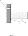
- FIGS. 1A and 1B show two examples of situation that can materialize in a highlight projection system. In both figures, there is a pinhole defect 2 at the same position of the diffuser 1.
- Beam projector module using laser describes a system with a sensor that senses light reflected back by a diffuser and shuts off the laser power if the reflected light falls below a threshold value as a result of the diffuser being detached from the frame.
- US 10069275 does not allow for the detection of each and every minute damage to the diffuser (like e.g. a pinhole defect) which can be located anywhere on the diffuser.
- the output signal of the detector can vary widely in function of the position across the diffuser of a pinhole defect in said diffuser.
- the detector will be unable to detect the pinhole.
- a detection system built according to US 10069275 may not be able to discriminate between the situations illustrated in Figures 1A and 1B .
- EP3121649 Light source device and image projection device having light source device discloses different solutions to monitor the state of a diffuser substrate by capacitive, thermal, magnetic or electrical sensors.
- the problem with this solution is that a significant change of an optical characteristic of the optical system (like e.g. a pinhole, a crack, etc%) is not guaranteed to cause a significant change in an electrical, thermal or magnetic characteristic of the optical system.
- Aperture (stop). An optical or mechanical component that limits the (lateral) size of a bundle of light rays.
- an aperture stop of an imaging system is the optical or mechanical element that limits angle of rays passing through the system from a source on the optical axis.
- the chief ray is the ray that passes through the center of the aperture stop, and the marginal rays are those that pass through the edge of the aperture stop.
- the size of the aperture stop determines the light-gathering capability of an optical device, and, thus, the brightness of its images.
- Reference to an "aperture” usually refers to the opening through which a light beam passes whereby the aperture limits the extent of the beam incident on the aperture stop.
- Telecentric Lens A compound lens system that has its entrance and/or exit pupil at infinity. This means that the chief rays, i.e. oblique rays that pass through the center of the aperture stop, are parallel to the optical axis in front of or behind the compound lens system, respectively.
- Object-space Telecentric Lens A compound lens system that has its entrance pupil at infinity. Rays originating from the object parallel to the optical axis pass through the center of the aperture stop.
- Image-space Telecentric Lens A compound lens system that has its exit pupil at infinity. Rays incident on the image parallel to the optical axis pass through the center of the aperture stop.
- Bi-telecentric Lens A compound lens system that has both its entrance and exit pupil at infinity.
- a base projector is a traditional projector with uniform illumination which comprises an amplitude modulator per color or one amplitude modulator with the primary colours being presented in sequence to the amplitude modulator.
- a base projector is an optical device that projects a full image such as full moving images onto a surface. To create a full image (rather than a highlight), a uniform illumination is applied to an amplitude modulator per color.
- Optical Diffuser An optical diffuser (also known as a diffuser) diffuses light evenly in a wide variety of applications. Optical Diffusers cause light to spread evenly across a surface thereby removing or minimizing bright spots. Optical Diffusers are also ideal for use as screens or targets in imaging applications. Optical Diffusers are also known as Light Diffusers in many illumination applications. The exit of Optical Diffusers typically has rays at a wide range of different angles.
- Diffuse light from an optical diffuser can, for instance, be obtained by reflecting light from a white surface, or by transmitting light through a translucent material, including ground glass, certain plastics, holographs, opal glass, frosted glass, greyed glass or, for example, by surface treatments such as sand blasting one or both surfaces of a substrate (e.g. glass or another transparent material) or by mixing small particles (e.g. titanium dioxide) in a resin that can be coated on a substrate before being polymerized.
- a translucent material including ground glass, certain plastics, holographs, opal glass, frosted glass, greyed glass or, for example, by surface treatments such as sand blasting one or both surfaces of a substrate (e.g. glass or another transparent material) or by mixing small particles (e.g. titanium dioxide) in a resin that can be coated on a substrate before being polymerized.
- a translucent material including ground glass, certain plastics, holographs, opal glass, frosted glass
- a particular type of diffuser is the phosphor type diffuser that converts the incident wavelength to light with longer or shorter wavelengths than the wavelength of the incident light.
- the diffuser sheet can be a bulk diffuser or a surface diffuser.
- a state of the art diffuser is, for instance, a frosted glass diffuser from Sigma Koki, Japan.
- Figure 1C shows, as an example, the increase of the intrinsic étendue with a diffuser in an illumination system.
- the diffuser Assuming that a collimated laser beam in an illumination system, with circular cross section and diameter d 0 , is incident on a diffuser sheet, the diffuser has a scattering half cone angle ⁇ 1 and the light emitting area of the diffuser, seen from position to the right, becomes a circle with diameter d 1 .
- a schematic image is shown in Figure 1C . Due to the scattering of the diffuser sheet, d 1 is greater than d 0 .
- the étendue is increased to a value d 1 2 ⁇ 2 4 sin 2 ⁇ 1 .
- a Gaussian diffuser scatters light completely randomly. When a narrow angle beam of light is directed through a Gaussian diffuser, the output has the typical Gaussian bell-shaped light intensity profile distribution.
- a diffuser is typically characterized by its Full Width Half Maximum (FWHM) angle. The larger the FWHM angle, the stronger the diffuser.
- FWHM Full Width Half Maximum
- Diffusers have a typical feature size determined by the typical size of the surface structure in case of a surface diffuser or by the typical size of a particle in case of a bulk diffuser. Only when a light beam is significantly larger than the typical feature size of the diffuser, can the average intensity and angle profile be guaranteed.
- a beam of coherent light is light in which the phases of all electromagnetic waves at each point on a line normal to the direction of the beam are identical.
- Coherent light is usually monochromatic, and the most common source of such light for practical uses is from a laser.
- An exit pupil is a virtual aperture in an optical system and is the image of the aperture stop in the optics that follow it. Only rays which pass through this virtual aperture can exit the system. Instead of “exit pupil” the term “Ramsden disc” has been used.
- the exit pupil of a projection lens in a projector is the optical image of the aperture stop in the projection lens as seen through the back of the projection lens (i.e. the image side or projection screen side). Optical elements between the projection lens aperture stop and the screen will produce a magnified or diminished image of the physical aperture that is displaced from the physical location of the aperture stop.
- the projection lens exit pupil is the virtual image of the projection lens aperture stop as seen by an observer standing in between the projector and the projection screen.
- FWHM Full width at half maximum
- Figure 1D illustrates this with a function f reaching a maximum value f max .
- the full width at half maximum (FWHM) is the difference x 2 - x 1 .
- Highlight projector See highlighter projector.
- a highlighter projector can be a projector which comprises a dual modulation stage.
- a first modulation stage the light from the source is distributed, i.e. steered, to provide a high illumination level at positions where the final image has a high intensity (i.e. the provision of the highlights) and a low illumination level at positions where the final image has a low intensity.
- the first modulation stage may comprise, for example, a phase modulator or a phase only modulator per color.
- a second modulation stage may comprise an amplitude modulator per color to attenuate the illumination profile delivered by the first modulation stage in order to provide the precise brightness and color for each pixel in the image. The second modulation stage can be said to trim the illumination profile delivered by the first modulation stage.
- a hybrid projector is a projector which combines the functionality of a Highlighter projector and a Base projector, while using only one amplitude modulator per color. A portion of the light is processed by the phase modulator to generate a highlight illumination pattern onto the amplitude modulator, another portion of the light is uniformly distributed onto the amplitude modulator to be used for creating the projected image.
- International standard providing requirements regarding photobiological safety of the optical radiation emitted by image projectors.
- Dual Projector setup A dual projector setup combines a Base Projector and a Highlighter projector to create a combined image.
- the two images to be projected can be combined onto the screen or the optical paths can be combined into a single projection lens.
- the term Dual projector setup will be used when the base image and the highlight image are each processed by a separate amplitude modulator.
- the amplitude modulator can be a reflective amplitude modulator such as, for instance, a digital micromirror array (DMD) or an LCOS.
- the amplitude modulator can also be a transmissive amplitude modulator such as light valve whereby an LCD is an example, but the absorption of light in the LCD can limit the power of the laser light that can be used.
- Amplitude modulator phase modulator, transmissive or reflective spatial light modulator or light valve.
- phase modulator or a phase only modulator is a device which introduces phase variations on an incident wavefront, e.g. light wavefront.
- phase patterns are applied with such a resolution that it creates a smooth and low detail image which can be projected onto an amplitude modulator.
- Different technological designs can be used to provide a phase modulator which can be reflective or transmissive.
- These devices include microelectromechanical (MEMS) displays, which provide a very fast temporal response but a low spatial resolution.
- MEMs devices can be configured to be used as phase modulators but in most cases these devices will actually be used as mirrors to deflect light and send it to a desired spot, i.e. as amplitude modulators. These then work in refractive mode, whereas phase modulators work in diffractive mode.
- Other suitable phase modulators are transmissive pixelated Liquid Crystal (LC) and reflective pixelated Liquid Crystal On Silicon (LCOS) modulators.
- An amplitude spatial light modulator is a device which directs incident light pixel-by-pixel towards a projector, e.g. a projector lens or to a dump or sink. In embodiments of the present invention, it creates a sharp image but has the disadvantage that light is dumped.
- a spatial light modulator which can be reflective or transmissive.
- These devices include microelectromechanical (MEMS or LCOS) displays, which provide a very fast temporal response.
- MEMs devices can comprise an array of tiltable mirrors to deflect light on a pixel-by-pixel basis and send it to a desired spot, i.e. towards the projector lens or to a sink or dump.
- Deformable or tiltable mirrors as used, for example, in the field of adaptive optics can also be used.
- Transmissive light valves such as LCD displays can also be used, which include liquid crystal on silicon (LCoS) reflective devices, which have the advantage of offering a high spatial resolution, high speed and a high pixel fill factor.
- LCD displays liquid crystal on silicon
- Liquid crystal displays used in transmission can also be used.
- Dynamically addressable phase modulating elements for use in embodiments of the present invention include reflective 2D arrays of reflective phase controlling elements or can include transmissive 2D arrays, e.g. of controllable liquid crystal elements. These elements have the property that the elements can be controlled to selectively retard the phase of laser light, effectively causing a change in path-length.
- Devices that can controllably adjust the phase of light of different areas include Phase Modulating Devices (PMD). PMDs may be transmissive or reflective. Some PMDs can individually control phase in a 2D array made up of a large number of pixels.
- Dynamically-addressable phase modulating elements can have one or more scanning mirrors, such as a 2D or 3D microelectromechanical system (MEMS), (e.g. DMDs) can be used.
- MEMS microelectromechanical system
- Spatial light modulator is a general term describing devices that are used to modulate amplitude, phase, or polarization of light waves in space and time. For example, applying a voltage leads to a variable tilt of the liquid crystal molecules due to their electrical anisotropy. As liquid crystal molecules also show optical anisotropy, this tilt changes the refractive index of the liquid crystal molecules which causes a modified optical path length within the liquid crystal cell. The addressed gray level is, hence, converted into a phase level.
- Embodiments of the present invention make of use a spatial light modulator in phase modulation mode for light steering.
- Phase modulator or phase panel is a diffractive optical element, for example an electrically addressed liquid-crystal spatial light modulator, a liquid crystal on silicon spatial light modulator all of which provide phase modulation.
- Spatial Light Modulator systems can be based, for example, on translucent (LCD) or reflective (LCOS) liquid crystal micro-displays.
- phase modulation devices can include: Spatial light modulators (SLM) having a 2D array of pixels, in which the drive level addressed at a pixel correlates to the phase delay applied to the light impinging on that pixel.
- SLM Spatial light modulators
- a spatial modulator can simultaneously change the state of polarization of the light.
- An example is a transmissive liquid-crystal display, or a reflective liquid crystal-on- Silicon display (LCoS)).
- LOC liquid crystal-on- Silicon display
- SLM can be designed to affect the phase delay of that pixel, but not its polarization.
- An acousto-optical modulator also called a Bragg cell can affect the deflection angle of the incoming light, its phase, frequency and polarization characteristics.
- a grating light valve includes an addressable array where in each pixel or element can vary the phase of the impinging light by mechanically varying the path length.
- Deformable Mirrors can be either continuously deformable mirror surface with an array of control points, or arrays of discrete, individually modulated reflective pixels.
- Steering light / Light steering relates to redistributing light so that it forms a pattern. This is best achieved by a phase modulator or phase only modulator.
- a phase modulator or phase only modulator By using positive reinforcing interference and negative interference of parts of a coherent light beam, such as a laser, an image can be produced with higher light intensity where one wants to have highlights.
- This highlight image or illumination can be combined with the output of a basic projector to create a highlighted image. There are various ways in which the highlighted image and the basic image can be combined.
- Light steering differs from amplitude modulation e.g. with a DMD.
- Mirror elements of such a modulating device only have two states: reflecting towards a projector lens for projection and display or reflecting to a light dump or sink. If an amplitude modulator is used to generate highlights, then this will be done with a lower efficiency than a phase modulator because of the dumped light. It also means that the highlighting is less intense.
- Shaped light SL refers to highlights in an image which have been obtained by redistributing light, for example by means of a phase modulator. This differs from amplitude modulated light wherein the modulator has two states - one for passing light through and one for dumping the light. Hence, components of such an image are cancelled or allowed through whereas phase modulation redistributes the light of a light beam.
- PSF Point Spread Function
- the point spread function (PSF) describes the response of an imaging system to a point like target.
- a more general term for the PSF is a system's impulse response, the PSF being the impulse response of a focused optical system.
- the PSF in many contexts can be thought of as the extended blob in an image that represents a single point object. In functional terms it is the spatial domain version of the optical transfer function of the imaging system.
- Embodiments of the present invention provide any or all of a light source device, an image projection device having the light source device, a method of operating an image projection device having the light source device or a method of making a light source and/or a method of making an image projection device having the light source device.
- Embodiments of the present invention provide an optical apparatus and a method configured to monitor a state of a diffuser illuminated by a coherent light source, and the use of such a system or method in a projector.
- the optical apparatus and method may be configured to detect the status of one or more diffusers and to generate signals such as alarm signals when a failing diffuser is detected.
- Embodiments of the present invention provide a laser projector safety apparatus and a laser projector safety method to reduce the risk of eye damage.
- shaped light e.g. highlights
- base light when shaped light (e.g. highlights) and base light are combined based on their polarization, it is possible to separate the shaped light and the base light before, for example right before, it reaches the photodetector by using a polarizer positioned between the sampling plate and the detector. Then, the majority of the light falling onto the detector is coming from the highlight path.
- a small residual leakage of base illumination can be tolerated as long as it is significantly weaker than the highlight illumination (for example ⁇ 20% of the highlight illumination).
- Embodiments of the present invention provide any or all of a light source device, an image projection device having the light source device, a method of operating an image projection device having the light source device or a method of making a light source and/or a method of making an image projection device having the light source device.
- Embodiments of the present invention provide an optical apparatus and a method configured to monitor a state of a diffuser illuminated by a coherent light source, and the use of such a system or method in a projector.
- the optical apparatus and method may be configured to detect the status of one or more diffusers and to generate signals such as alarm signals when a failing diffuser is detected.
- Embodiments of the present invention provide a laser projector safety apparatus and a laser projector safety method where the alarm signal is used to shut down the laser source or reduce the power of the laser source in order to reduce the risk of eye damage.
- Embodiments of the present invention provide as a first aspect an optical apparatus configured to monitor a state of a diffuser illuminated by a light source, at least one light beam comprising at least one bundle of rays of light exiting the diffuser being for illumination of a transmissive or reflective spatial light modulator of a projector, further comprising a sampler that samples the light beam exiting the diffuser and re-directs the light beam sample towards a detection system, wherein the detection system is coupled to an analyzer that generates a signal when an anomaly is detected in the distribution of the light intensity in a cross-section of the sample of the light beam.
- a processing device may have memory (such as non-transitory computer readable medium, RAM and/or ROM), an operating system, optionally a display such as a fixed format display, ports for data entry devices such as a keyboard, a pointer device such as a "mouse", serial or parallel ports to communicate other devices, network cards and connections to connect to any of the networks.
- memory such as non-transitory computer readable medium, RAM and/or ROM
- an operating system optionally a display such as a fixed format display, ports for data entry devices such as a keyboard, a pointer device such as a "mouse”, serial or parallel ports to communicate other devices, network cards and connections to connect to any of the networks.
- the software can be embodied in a computer program product adapted to carry out the functions of any of the methods of the present invention when the software is loaded onto a computer and executed on one or more processing engines such as microprocessors, ASIC's, FPGA's etc.
- processing engines such as microprocessors, ASIC's, FPGA's etc.
- any of the embodiments of the present invention can incorporate a computer system capable of running one or more computer applications in the form of computer software.
- the methods described with respect to embodiments of the present invention above can be performed by one or more computer application programs running on the computer system by being loaded into a memory and run on or in association with an operating system such as Windows TM supplied by Microsoft Corp, USA, Linux, Android or similar.
- the computer system can include a main memory, preferably random-access memory (RAM), and may also include a non-transitory hard disk drive and/or a removable non-transitory memory, and/or a non-transitory solid-state memory.
- Non-transitory removable memory can be an optical disk such as a compact disc (CD-ROM or DVD-ROM), a magnetic tape, which is read by and written to by a suitable reader.
- the removable non-transitory memory can be a computer readable medium having stored therein computer software and/or data.
- the non-volatile storage memory can be used to store persistent information that should not be lost if the computer system is powered down.
- the application programs may use and store information in the non-volatile memory.
- the software embodied in the computer program product is adapted to carry out the functions disclosed in a method of any of the aspects 45 to 86 when the software is loaded onto the respective device or devices and executed on one or more processing engines such as microprocessors, ASIC's, FPGA's etc.
- Any of the above software may be implemented as a computer program product which has been compiled for a processing engine in any of the servers or nodes of the network.
- the computer program product may be stored on a non-transitory signal storage medium such as an optical disk (CD-ROM or DVD-ROM), a digital magnetic tape, a magnetic disk, a solid-state memory such as a USB flash memory, a ROM, etc.
- aspect 87 relates to a computer program product comprising a computer program which, when executed on a processor, executes the method of any of the aspects 45 to 86 and aspect 88 relates to a signal storage means storing the computer program of aspect 87.
- Figure 2 (2A to 2H) shows an example of an apparatus that can monitor the state of a diffusor illuminated by a light beam and in particular a coherent light beam, in accordance with an embodiment of the present invention.
- This embodiment also includes a method comprising the step of monitoring the state of a diffusor illuminated by a light beam and in particular a coherent light beam.
- the apparatus or method can be used as a diffusor failure detection apparatus or method respectively.
- the apparatus or the method can be used in a projector.
- the apparatus or the method comprises or makes use of a sampler that samples the light beam exiting the diffusor and re-directs it towards a detection apparatus.
- the apparatus can include a means for redirecting the sampled beam to the detection apparatus.
- the detection apparatus can comprise or include one or more detectors.
- the one or more detectors can include photosensors, photodiodes, photoresistors, phototransistors or similar and drive electronics to monitor these photosensors.
- the drive electronics or the method is configured to detect changes in the sampled light beam and to output a signal such as an alarm signal when the changes in the light beam indicate a damaged or failing diffusor.
- the method or the drive electronics may be configured also reduce the intensity of a laser light source, or block or deflect the laser light beam or turn off the laser light beam.
- the detection apparatus can be an integral part of a projector or it can be an optical assembly or a retro-fit apparatus for a projector.
- FIG 2A an example of an optical system, which is a diffusor failure detection apparatus 10, is shown where a diffusor 11 is imaged by a set of lenses 12 and 20 onto an amplitude modulator such as a reflective or transmissive spatial light modulator such as a DMD, and LCOS or a light valve 21 such as an LCD; with an aperture plane 13 and aperture stop 14 with an aperture 19 provided, for example, after the first lens 12.
- the diffuser 11 can be a stationary or moving diffusor.
- a moving diffusor is preferred to avoid that the structure of the diffuser material becomes visible in the projected image, for example.
- a sampler for example in the form of a sampling plate 15, is configured to couple out a small fraction 16r of the light 16i incident on the sampler such as plate 15.
- the fraction of light 16r can be, for example, 5% or less of the incident light 16i, for example 0.01-3% and in particular 5% or less of the intensity or optical power of the light beam 16i, for example 0.01-3%.
- the reflected light 16r goes to a detector system 18.
- the transmitted light 16t goes on towards the aperture plane 13 through the aperture 19 and beyond via a second lens 20 to illuminate a reflective or transmissive spatial light modulator such as a DMD or an LCOS or a light valve 21 of a projector.
- the sampler such as plate 15 can, for instance, be a glass plate.
- An anti-reflection coating (not shown) can be present on one or both sides 15A and 15B of the sampler, e.g. the glass plate 15, to reduce the transmission losses.
- the residual reflection can, for instance, be higher than 0.01 % and is preferably lower than 1% to 5%.
- optical distance A optical distance B
- the optical distance A is taken on the optical axis OA which corresponds to a central light ray.
- the optical distance B is taken along the reflection 16r of the central ray on the sampler such as the sampling plate 15.
- the light distribution in a cross section of aperture 19 in aperture plane 13 of the light beam 16t will be substantially the same as the light distribution in a cross section of the reflected light beam 16r of the sampled aperture plane 17.
- a sampler for example in the form of a sampling plate 15, is configured to couple out a small fraction of the light incident on the sampler such as plate 15.
- the fraction of light reflected can be e.g. 5% or less of the incident light, e.g. 0.01-3% and in particular 5% or less of the intensity or optical power of the incident light beam 16i, for example 0.01-3%.
- the reflected light 16r goes to a detector system 18.
- the transmitted light 16t goes on towards the aperture plane 13 and beyond via a second lens 20 to illuminate a reflective or transmissive spatial light modulator such as a DMD or an LCOS or a light valve 21 of a projector.
- the sampler such as plate 15 can, for instance, be a glass plate.
- An anti-reflection coating (not shown) can be present on one or both sides of the sampler e.g. the glass plate 15 to reduce the transmission losses.
- the residual reflection 16r can, for instance, be higher than 0.01 % and is preferably lower than 1% to 5%.
- the sampled aperture plane 17 can be found at a second distance equivalent to a first distance being the optical path length between the sampler, i.e. the sampling plate 15 and the aperture plane 13, the sampled aperture plane 17 can be found.
- the first optical distance is taken on the optical axis which corresponds to a central light ray.
- the second optical distance is taken along the reflection 16r of the central ray on the sampler such as the sampling
- the diffuser 11 can be a stationary or moving diffusor.
- a moving diffusor is preferred to avoid that the structure of the diffuser material becomes visible in the projected image, for example.
- the optical system that images the diffuser 11 onto the reflective or transmissive spatial light amplitude modulator such as the DMD or LCOS or the light valve 21 preferably is configured to be bi-telecentric in any of the embodiments of the present invention.
- the optical system should minimally be configured to be substantially object space telecentric in any of the embodiments of the present invention.
- Light rays that exit the diffuser 11 parallel to the optical axis are focused by lens 12 in the center of the aperture 19 of the aperture stop 14.
- Figure 2B shows how different rays of light exiting the diffuser 11 from either position P1 or P2, (which can be anywhere else on the surface of the diffuser 11) with the same angle ⁇ to the optical axis will intersect each other at the same point in the aperture 19 of the aperture stop 14.
- a ray of light R 1 exiting the diffuser 11 at a point P1 with an angle ⁇ to the optical path will arrive at the point P ⁇ in the aperture 19 of the aperture plane 13.
- a ray of light R' 1 exiting the diffuser 11 at a point P2 (which can be anywhere else on the surface of the diffuser 11) with an angle ⁇ to the optical path will arrive at the same point P ⁇ in the aperture plane 13.
- a ray of light R2 exiting the diffuser 11 at a point P1 with an angle - ⁇ to the optical path will arrive at the point P- ⁇ in the aperture plane 13.
- a ray of light R' 2 exiting the diffuser 11 at a point P2 (which can be anywhere else on the surface of the diffuser 11) with an angle - ⁇ to the optical axis will arrive at the same point P- ⁇ in the aperture plane 13.
- Some of the light rays R ⁇ will be reflected by the sampler such as the sampling plate 15. Those light rays will end up at the same point in the sampled aperture plane 17. For instance, all the light rays that exit the diffuser 11 with an angle ⁇ to the optical axis(regardless of the position on the surface of the diffuser 11) and that are reflected on the sampler such as the sampling plate 15 will arrive at the same point P' ⁇ in the sampled aperture plane 17. All the light rays that exit the diffuser 11 with an angle - ⁇ to the optical axis (regardless of the position on the surface of the diffuser 11) and that are reflected on the sampler such as the sampling plate 15 will arrive at the same point P'- ⁇ in the sampled aperture plane 17.
- Figure 2C shows in between the lens 12 and the aperture stop 14, a sampler e.g. in the form of a sampling plate 15 is configured to couple out a small fraction of the light incident on the sampler such as plate 15.
- the fraction of light reflected can be, for example, 5% or less of the incident light, for example 0.01-3% and in particular 5% or less of the intensity or optical power of the light beam 16i, for example 0.01-3%.
- the reflected light goes to a detector system 18.
- the transmitted light goes on towards the aperture plane 13 and beyond via a second lens 20 to illuminate a reflective or transmissive spatial light modulator such as a DMD or an LCOS or a light valve 21 of a projector.
- the sampler such as plate 15 can, for instance, be a glass plate.
- An anti-reflection coating (not shown) can be present on one or both sides of the sampler, for example the glass plate 15, to reduce the transmission losses.
- the residual reflection can, for instance, be higher than 0.01 % and is preferably lower than 1% to 5%.
- the sampled aperture plane 17 can be found at a second distance equivalent to a first distance being the optical path length between the sampler, i.e. the sampling plate 15 and the aperture plane 13, the sampled aperture plane 17 can be found.
- the first optical distance is taken on the optical axis which corresponds to a central light ray.
- the second optical distance is taken along the reflection 16rof the central ray on the sampler such as the sampling plate 15.
- the diffuser 11 can be a stationary or moving diffusor.
- a moving diffusor is preferred to avoid that the structure of the diffuser material becomes visible in the projected image, for example.
- the optical system that images the diffuser 11 onto the reflective or transmissive spatial light amplitude modulator such as the DMD or LCOS or the light valve 21 preferably is configured to be bi-telecentric.
- the optical system should minimally be configured to be substantially object space telecentric. Light rays that exit the diffuser 11 parallel to the optical axis are focused by lens 12 in the center of the aperture stop 14.
- shaped light SL illuminates a surface S of area dA of the diffuser 11 around a first point P1.
- S can be, for example, a disc centered on P1.
- the distribution D(x,y) of light across the disc can be arbitrary. For the sake of simplicity, we take as an example a top hat distribution across the surface S.
- the rays of light that exit the diffuser 11 will fill the (opening 19 of the) aperture stop 14 and the image of the aperture stop 14 in the sampled aperture plane 17 as was described earlier.
- Figure 2C shows how different rays of light exiting the diffuser 11 with the same angle ⁇ to the optical path will intersect each other at the same point in the aperture 19 of the aperture stop 14.
- a ray of light R 1 exiting the diffuser 11 at a point P1 within the surface S with an angle ⁇ to the optical path will arrive at the point P ⁇ in the aperture 19 of the aperture plane 13.
- a ray of light R2 exiting the diffuser 11 at the point P1 within surface S with an angle - ⁇ to the optical path will arrive at the point P- ⁇ in the aperture plane 13.
- Some of the light rays R ⁇ will be reflected by the sampler such as the sampling plate 15. Those light rays will end up at the same point in the sampled aperture plane 17. For instance, all the light rays that exit the diffuser 11 with an angle ⁇ to the optical path (regardless of the position on the surface S of the diffuser 11) and that are reflected on the sampler such as the sampling plate 15 will arrive at the same point P' ⁇ in the sampled aperture plane 17. All the light rays that exit the diffuser 11 with an angle - ⁇ to the optical path (regardless of the position on the surface S of the diffuser 11) and that are reflected on the sampler such as the sampling plate 15 will arrive at the same point P'- ⁇ in the sampled aperture plane 17.
- the light intensity D1(x,y) across the input surface of the diffuser 11, the light intensity f1(x,y) across the (opening 19 of the) aperture stop 14 and the light intensity f1'(x,y) across the sampled aperture plane 17 are shown on figure 2D .
- we only give the light intensity along a single direction e.g. y, the direction y and z are in the plane of figure 2C and the direction x is perpendicular with the plane of figure 2C ).
- Figure 2E shows a diffusor failure detection apparatus 10 as in Figure 2C .
- shaped light illuminates a surface S of area dA around a second point P2 different from P1 that is shown in Figure 2C , with the same light across the surface S around P2 as it was the case in Figure 2C around the first point P1.
- a diffusor failure detection apparatus 10 for example in a light steered projector, provided that the optics that image the moving diffuser 11 onto the reflective or transmissive spatial light amplitude modulator such as a DMD or an LCOS or the light valve 21 such as an LCD are object space telecentric, the light distribution across the aperture stop 14 and across the sampled aperture plane 17 is independent of the actual light shaping. Note that it is preferred if shaping of the light has no effect on the angle at which the light is incident on the diffuser 11. In practice, this incident angle can be somewhat affected by the light steering this will be discussed further. This effect is small enough however, such that the light distribution across the opening 19 of the aperture stop 14 and across the sampled aperture plane 17 is effectively largely independent from the actual light shaping.
- FIG 2G another diffusor failure detection apparatus 10 is shown similar to the one in Figures 2C and 2E and having the same optical components.
- the diffusor 11 is damaged at P1.
- a hole H with a surface S (e.g. a disc with area dA and centered on PI) as an example of a defect or damage. If shaped light illuminates the surface S, the rays of light exit the diffuser 11 without having been diffused as they go through the hole H. Since all the rays of light exit the surface of the diffuser 11 with an angle of 0°, the rays of light not reflected by the sampling plate 15 will end up at the same point P 0 in the center of the opening of the aperture stop 14. The rays of light reflected by the sampling plate 15 will end up at the same point P' 0 in the center of the opening of the sampled aperture plane 17.
- Figure 2H shows how the light intensity D3(x,y) varies across the input surface of the diffusor 11, across the opening 19 of the aperture stop 14 and across the sampled aperture plane 17. While D3 in Figure 2H and D1 in Figure 2D are identical, the profile of the light intensity across the opening 19 of the aperture stop 14 f3(x,y) and across the sampled aperture plane 17 f'3(x,y) are very different from those on Figure 2D .
- the light distributions with the damaged diffuser f3(x,y) and f'3(x,y) have a much higher peak intensity and a more narrow FWHM than the light distributions with the undamaged diffuser f1(x,y) and f'1(x,y) illustrated in dotted lines in Figure 2H .
- the sampler such as the sampling plate 15 reflects a fraction of the light rays.
- the reflected light rays will intersect each other in the sampled aperture plane 17, i.e. light rays, that exit the diffuser 11 with the same angle ⁇ and that are reflected by the sampler such as the sampling plate 15, will intersect at the same point in the sampled aperture plane 17.
- Damage to the diffuser 11 will be visible as a change in light distribution in the aperture plane 13 and in the sampled aperture plane 17.
- a change can be detected by a detector system 18 which may include photosensors, photodiodes, photoresistors, phototransistors or similar and drive electronics to monitor these photosensors.
- the drive electronics can be configured to detect changes in the sampled light beam (such as a change in FWHM) and to output a signal such as an alarm signal when the changes in the light beam indicate a damaged or failing diffusor 11.
- the drive electronics may also react to receipt of the output signal of the diffusor failure detection apparatus 10 by reducing the intensity of a laser light from the laser light source, or blocking or deflecting the light beam from the laser light source or turning off the light source.
- Bright zones in the aperture plane 14 do not correspond to a region on the transmissive or reflective amplitude modulator 21 such as a DMD or a light valve like an LCD of the projector or on screen.
- Points P1 and P2 are imaged on a different position on the transmissive or reflective amplitude modulator 21 such as a DMD or an LCOS or a light valve like an LCD of a projector but deliver the same intensity profile in the aperture plane 13.
- a crack or hole in the diffusor 11 will often result in an increase in light intensity close to the center of the aperture 19 of aperture stop 14 or more generally at, or close to, the point P0 of the aperture stop 14 where rays of lights exiting the diffusor 11 with an angle of 0° are directed by the lens 12.
- the drive electronics can output a signal such as an alarm signal or the laser light from the laser light source can be blocked, reduced in intensity, deflected or the light source shut down.
- the detector 18 can be a single photodetector.
- a hole in the diffusor 11 will result in an increase of the light intensity at P' 0 as illustrated on Figure 2G .
- a single photodetector at that position can detect an increase in light intensity.
- the total light flux through the system might not be constant.
- the light thoughput efficiency of a light steering system can also vary with the light steering pattern targeted. For example, steering towards the center of the image can be more efficient than steering towards the corners.
- a threshold of detection for a single photodetector can be prone to a false negative detection when the signal from the photodetector always remains below threshold even if the diffusor 11 is not working properly.
- Another disadvantage of the single photodetector system is that a false positive signal could be generated when the percentage of light to be outcoupled by the sampler, such as the sampling plate 15, increases, for example due to temperature effects.
- the detector 18 can be an array of photodetectors with 2 or more photodetectors.
- the detection system can be configured to evaluate the relative intensity distribution between the different photodetectors. If the distribution changes or is nonuniform, a signal can be generated such as an alarm signal. Alternatively, the output of the light source can be reduced or blocked or deflected or the light source can be shut down.
- the detector system may include an array of photosensors, photodiodes, photoresistors, phototransistors or similar and drive electronics to monitor these photosensors.
- the diffusor failure detection apparatus 10 and/or its drive electronics can be configured to detect changes in the sampled light beam and to output a signal such as an alarm signal when the changes in the light beam indicate a damaged or failing diffusor 11.
- the drive electronics may also reduce the intensity of a laser light source, or block or deflect the light beam or shut down the light source.
- the array can be linear (i.e. 2 or more photodetectors distributed over a straight line) or a 2D array (with 3 or more photodetectors distributed in a plane).
- the array can be regular (i.e. the photodetectors are positioned at regular intervals) or not.
- the position of the photodetectors can take advantage of symmetries present in the system.
- the light distribution (when the diffusor 11 is intact) can be symmetrical around the optical axis of the system.
- the photodetectors can be distributed along a line perpendicular with and intersecting the optical axis.
- Figures 3A , 3B and 3C illustrate alternative dispositions of photo-sensors like, for example, photodiodes, photoresistors, phototransistors or similar of detector 18 in the sampled aperture plane 17.
- the photo-sensors can be part of any of the diffusor failure detection apparatus10 as shown in any of Figures 2A , 2B , 2C , 2E , 2G and 5 .
- a photosensor 31 is positioned at the center of the intensity profile.
- the photosensor 31 can be a photodiode, photoresistor, phototransistor or similar and drive electronics to monitor this photosensor.
- a comparator circuit can be provided that compares the value of the light intensity given by the photosensor 31 with a fixed threshold.
- a first photosensor 31 is positioned at the center of the intensity profile and a second photosensor 32 is positioned at e.g. half the maximum radius R Max of the intensity profile.
- the photosensor 31 and/or 32 can be a photodiode, photoresistor, phototransistor or similar and drive electronics to monitor these photosensors.
- a line sensor with multiple photosensor elements 33 is positioned to extend from the center of the intensity profile to the edge of the intensity profile.
- the multiple photosensor elements can include photodiodes, photoresistors, phototransistors or similar and drive electronics to monitor these photosensors.
- damage to the diffusor 11 will result in a change of the light intensity profile in the sampled aperture plane 17.
- the ratio of the light intensity at the position of the first sensor and of the light intensity at the position of the second sensor will change in function of the state of the diffusor.
- more than two detectors can be used.
- the diffusor failure detection apparatus 10 and/or the drive electronics can be configured to detect changes in the sampled light beam and to output a signal such as an alarm signal when the changes in the light beam indicate a damaged or failing diffusor.
- the diffusor failure detection apparatus 10 or the drive electronics may also reduce the intensity of laser light from a laser light source, or block or deflect the light beam or shut down the laser light source.
- a comparator circuit that compares the value of the light intensity given by the second photosensor 32 with a fraction (e.g. 1/3) of the value of the light intensity output by the first photosensor 31 or compares n times (e.
- the output of the second photosensor 32 will be higher than e.g. 1/3 of the center value. If the diffuser 11 fails, the brightness at an angle (e.g. 6°) will stay roughly the same while the center brightness increases and the second photosensor 32 will measure below 1/3 of the first photosensor 31, thereby causing the output of the comparator circuit to flip.
- This output signal can be used as an alarm signal or to trigger a reduction in light intensity or to shut down the laser light source or to block, divert or reduce its power.
- the sampler such as the sampling plate 15 has a certain thickness, a double image may exist in the sampled aperture plane 17 of any of the embodiments of the present invention.
- a reflection from the front side 15A of the sampler such as the sampling plate 15 can overlay with a reflection 15B from the backside of the sampler such as the sampling plate 15.
- this offset will be relatively small and the image in the sampled aperture plane 17 is still adequate, for example for systems with low resolution detection.
- Low resolution detection means for example, that the detector 18 has a lower resolution than the transmissive or reflective amplitude modulator such as a DMD or a light valve 21 like an LCD of a projector (e.g.
- LC panel or micro-mirror device illuminated by the transmitted light 16t or that detection of a problem does not require the same resolution as that of the transmissive or reflective amplitude modulator 21 such as a DMD or a light valve like an LCD of a projector, when analyzing the light distribution across the sampled aperture plane 17.
- the transmissive or reflective amplitude modulator 21 such as a DMD or a light valve like an LCD of a projector
- the sampler can be a glass plate 15 and can, for instance, be 1 mm thick. With a typical angle of 45° between the optical axis OA and the sampler such as the sampling plate 15, the reflections on both sides of the sampler such as the sampling plate 15 (which can be a glass plate) will be offset by ⁇ 2 mm. This must be compared to the size of the aperture 19 of the aperture stop 14 which has a typical diameter of 20 mm to 50 mm.
- Figure 4 illustrates this
- the image 40 in the sampled aperture plane 17 comprises a first image 41 obtained by reflection of the light on the first surface 15A of the sampler such as the sampling plate 15 and a second image 42 obtained by reflection of light on the second surface 15B of the sampler such as the sampling plate 15.
- the offset O separates corresponding points of the images 41 and 42 as illustrated on figure 4 . Offset O is small compared to diameter D.
- the thickness of the sampler such as the glass plate 15 is less critical. If the line sensor is positioned in the same direction as the offset, then a sampler such as the glass plate 15 of 5 mm thick would create an offset of the same order of magnitude as the distance between two photodetectors of the detector array 18 and the detection could or would no longer work optimally.
- an Anti-Reflection coating is provided on a single side of the sampler such as the sampling plate 15. The reflection on the side of the sampler such as the sampling plate 15 without AR coating becomes dominant.
- the sampler such as the sampling plate 15 is very thick (e.g. more than 10mm) such that the imaged reflections are separated in the sampling aperture plane 17.
- the detector 18 is positioned so as to see only one of the reflections.
- the thickness of the sampler such as the sampling plate 15 is determined in function of the width of the incident light beam, the distance between photodetectors in the detector array 18 and the angle between the sampler such as the sampling plate 15 and the optical axis OA.
- a steered illumination e.g. steering light to a pattern of varying light intensity
- a conventional uniform base illumination for example as in a conventional projector.
- the steered illumination can function to provide highlighting, i.e. illumination can be steered to parts of a projected image to provide highlights while the other parts (with low and medium intensity) of the image itself are projected by a base illumination, for example using conventional projection.
- a base illumination for example using conventional projection.
- the total light flux of the base illumination profile can be higher than the total light flux of the steered illumination profile. For example, 30% steered light flux versus 70% base light flux.
- Figure 5 illustrates a further diffusor failure detection apparatus 10.
- Figure 5 shows how the relay optics 12 illustrated on any of Figures 2A , 2B , 2C , 2E or 2G can be adapted for use in a hybrid projector.
- the base light BL is emitted from a conventional projector illumination system, such as an integrator 311.
- Shaped light SL is received from a light shaper (not shown).
- the shaped light SL and the base light BL are polarized.
- the directions of polarization of the shaped light SL and the base light BL are orthogonal. Both light beams can be combined with a polarized beam combiner 33.
- the combined beam 16 goes through relay optics 12.
- a transmitted fraction 16t of the beam 16 passes through the sampler 15 (e.g. a glass plate) and moves on towards the aperture 14.
- a reflected fraction 16r e.g. less than 5%
- the sampler 15 is reflected by the sampler 15 towards the detector 18.
- the detection of a failure of a diffuser 11 in the diffuser plane 36 can be done on the combined light beams of the shaped light (SL) and the base light (BL).
- the shaped light SL may be necessary to isolate the shaped light SL from the base light BL before it reaches the detector 18. This can be the case if, for example, it becomes difficult to detect variability in the light distribution caused by a failure of diffusor 11 with a particular detector system 18 (i.e. because the output of the detectors is dominated by the light flux of the base light).
- the shaped light SL and the base light B are combined based on their polarization, it is possible to separate the shaped light and the base light right before it reaches the detector 18 by using a polarizer 34 positioned between the sampling plate 15 and the detector 18. Then, the majority of the light falling onto the detector 18 is coming from the highlight path.
- a small residual leakage of base illumination can be tolerated as long as it is significantly weaker than the highlight illumination (for example ⁇ 20% of the highlight illumination).
- a depolarizer 35 can be installed at the aperture plane 13, to make sure that the light transmitted to the transmissive or reflective amplitude modulator such as a DMD or a light valve like an LCD (not shown) of a projector has no preferential polarization direction; such that when the projector is combined with a 3D polarization switcher in front of the lens, base and highlight undergo equal transmission in both left and right perspective. Also, this depolarization step contributes to speckle reduction via polarization diversity.
- the light that is sampled with the sampler such as the sampling plate 15 before the depolarizer 35 however still has 1 polarization direction for the base illumination and an orthogonal polarization direction for the steered highlight illumination.
- a polarizer 34 installed in front of detection system 18 having a photosensor (e.g. single photodetector implementation) or photosensors (e.g. double detector or detector array implementation with multiple photodetectors) can block the base illumination while allowing the sampled highlight illumination to pass to detection system 18.
- a double diffuser can be used for the shaped light SL.
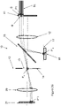
- Figure 6 shows a light steering system with a phase modulator or phase only modulator 40 steering light onto a first diffuser 41 in a first intermediate image plane 42.
- the first diffuser 41 can be a moving diffuser. If an incoming laser beam 43 were perfectly collimated, the phase modulator 40 would be able to concentrate all the light in a single focus point 44. Because, in practical implementations, the laser beam is not perfectly collimated but shows an angular spread 43S, the light will spread out from the focus point to what is called the Point Spread Function or PSF. Instead of a point 44, a surface 44S of finite area on the diffuser 41 is illuminated. This finite area is then imaged onto the second diffuser 47 with a surface 44S'.
- PSF Point Spread Function
- the typical feature size of the diffusers 41 and 47 should be significantly smaller than the size of this area (44S and 44S', respectively) to avoid the internal structure of the diffusors 41 and 47 appearing in the projected image.
- the typical feature size of the diffusers 41 and 47 should be less than one fifth of the PSF of the light steering system.
- the point spread function (PSF) at a first intermediate image 45 in the first image plane 42 and the second intermediate image 49 in the second intermediate image plane 48 typically is in the range of 5 to 20 % of the image width.
- the typical feature size of the diffusers 41, 47 should be smaller than 1 to 4% of the image width respectively.
- the diffusers 41, 47 would contain features that are larger than the PSF, then it is possible that the diffusers 41, 47 would not properly diffuse (e.g. the outgoing angles would be a subset of range+/- ⁇ ). It can even occur that the diffuser defect detection apparatus could be triggered as a result even if the diffusers are not broken or damaged.
- the features can still be significantly larger than the pixels of the projected image and the structure of the diffusers 41, 47 can become visible in the projected image. This can be mitigated or avoided by moving the diffuser(s) 41, 47 at a speed such that a high number (e.g. larger than 10) of diffuser features pass each pixel during the imaging period.
- a high number e.g. larger than 10
- the worst-case imaging period duration is the shortest pulse of the pulse-width-modulation scheme.
- the diffuser feature size and speed of motion comply with the above conditions, it should introduce diffusion angles according to the FWHM characteristics and deliver the desired distribution of light in the aperture plane as well as introduce angular diversity for despeckling and render the diffuser features invisible in the projected image.
- the acceptable laser exposure level can be exceeded significantly and eye damage could start to occur even after an extremely short exposure.
- the reaction speed requirement for the detection circuit 18 and a laser shutdown circuit become demanding.
- a single central photodetector of the detection system 18 in the sampled aperture plane 17 with finite dimensions could fail to detect the diffuser fault because the light is concentrated outside the active area of the photodetector.
- an additional safety measure can be to introduce a second intermediate image plane 48 with a second diffuser 47.
- the second diffuser 47 can be a moving diffusor. This second diffuser 47 will then be positioned at the position of diffuser 11 in Figure 2A (or 2B , 2C , 2E , 2G , 5 ).
- Relay optics 46 are preferably provided to image the first intermediate image 45 onto the second intermediate image 49. These relay optics 46 could have a magnification factor of 1 or a different magnification factor.
- This second diffuser stage guarantees that with either one of the diffusers 41, 47 failing, the light spot observed in the projection lens exit pupil will become somewhat smaller and the peak intensity higher, but light will not suddenly be concentrated into a point.
- Both diffusers 41, 47 preferably move at adequate speed as discussed above to introduce angular diversity for despeckling and to avoid that the structure of the diffuser 41 or 47 becomes visible in the projected image.
- the diffusers 41, 47 are dimensioned such that both diffusers 41, 47 contribute equally to the final spreading of the light across the aperture 19 and the projection lens pupil.
- the two diffusers 41, 47 can have identical strength if the relay optical system 46 has a magnification factor of 1. Diffuser strength can be understood in this context as diffusing angle. More strength means a larger diffusing angle.
- the first diffuser 41 can be a Gaussian diffuser with FWHM of 8.8° and the second diffuser 47 can be a Gaussian diffuser with a FWHM of 6.8°.
- the average incident angle on the first diffuser 41 will change if the focus spot is steered away from the center of the image toward the edges, for example to the top or the bottom.
- the distance between the phase modulator 40 and the first intermediate image plane 42 is not shown to scale, and the PSF is larger than it would be in a typical implementation, for reasons of clarity of the illustration. In an actual system the distance is around 20 times larger (and the divergence angle of the collimated incoming beam 20 times smaller). For example, with the phase modulator width and the intermediate image width both being 15mm the distance between the phase modulator and the first intermediate image plane 42 would typically be in the range of 150 to 250 mm.
- a typical divergence of the incoming beam would be in the range of +/- 0.1° till+/-0.2°.
- the variance introduced by steering the beam to the most extreme positions of the image would be in the range of+/- 2° till +/- 4°.
- the intermediate image 45 is only half the size of the transmissive or reflective amplitude modulator 21, such as a DMD or LCOS or a light valve like an LCD of a projector, then translating these angles to the transmissive or reflective amplitude modulator 21, such as a DMD or LCOS or a light valve like an LCD of a projector divides them by 2.
- steering introduces an angular shift at the transmissive or reflective amplitude modulator 21, such as a DMD or an LCOS or a light valve like an LCD of a projector, in the range of +/-1° till +/-2°.
- the diffuser(s) 41, 47 introduce angles to largely fill the full acceptance angle of the transmissive or reflective amplitude modulator 21, 40 e.g. DMD of around +/-10 degrees.
- DMD digital tomography
- the distribution of angles in the system is dominated by the action of the diffusers 41, 47, and, therefore, so is the brightness distribution in the aperture plane 13 and the sampled aperture plane 17.
- the light distribution in the aperture plane 13 (shown in Figures 2A , 2B , 2C , 2E , 2G and 5 ) changes significantly when either one of the two diffusers 41, 47 fails.
- Figure 7 illustrates the angular profile at the exit of the second diffuser 47 of Figure 6 .
- the curves are shown for different cone angles of the incoming laser light at the first diffuser 41 of Figure 6 going from 0° cone angle (no steering) to 3.5° cone angle (maximum steering angle).
- the first diffuser 41 has a Gaussian profile with a FWHM of 8,8°
- the second diffuser 47 has a Gaussian profile with a FWHM of 6.8°
- the magnification factor of the optics imaging the first intermediate image 45 onto the second intermediate image 49 is around 1.27. Note that 8.8°/1.27 is approximately equal to 6.8° such that both diffusers 41, 47 contribute equally to the final diffusing angle.
- the lower curves correspond to the normal situation where both diffusers 41, 47 are working properly.
- the curves have been normalized to a peak intensity of 1 for each cone angle individually.
- the higher curves correspond to the situation where one of the diffusers 41, 47 is failing. It can be seen that the incoming cone angle only has a small effect on the angular profile, while there is a significant effect caused by one of the diffusers 41, 47 failing. Hence, it is possible to discriminate between a normal situation with both diffusers 41, 47 operational and a situation where one of the diffusers 41, 47 is failing regardless of the angle profile variability introduced by the beam steering.
- corner brightness would need to more than 75% of the center brightness.
- a detector system 18 with 2 or more photosensors. Rather than a detection system 18 that looks at the brightness in the center of the aperture plane 13, 17 only, this embodiment provides a detector system 18 to actually look at the cross-section of the brightness profile. Since we largely expect the profile to be rotationally symmetrical (e.g. apart from a minor decentration caused be a variation in the dominant steering angle), it would be sufficient for the detection system 18 to have a line detector, as illustrated in Figure 3C , that senses the intensity from the center of the aperture to the edge of the aperture.
- the number of sensing elements comprised in the line sensor of the detection system 18 can be varied. The larger the number or sensing elements, the more accurate the profile can be sensed. However, it becomes more difficult to interpret the results. If the curves are smooth in both the normal condition and the failed diffuser condition, a minimal amount of sensing elements can be used. This is the case, for example, with the double Gaussian diffuser of Figure 6 setup as illustrated by the curves in Figure 7 .
- 6° is the angle at which the light ray departs from the second diffuser 47 relative to the optical axis.
- the comparator circuit is preferably configured to give a digital output that indicates either in a "no fault” or a "faulty" condition.
- the detection system 18 may be configured to generate a signal if the faulty condition is detected; whereby the signal can be an alarm signal.
- the detection system 18 may be configured to generate commands to reduce the intensity of the light emitted by the laser light source or to block or deflect the laser light or turn off the light source.
- the second sensor 32 In a normal situation with both diffusers 41, 47 working, the second sensor 32 will be higher than 1/3 of the center value, putting the output of the comparator to the "no fault" condition. But when either one of the diffusers 41, 47 fails, the brightness at a 6° angle will stay roughly the same while the center brightness increases and the second sensor 32 will measure below 1/3 of the first sensor 31, thereby causing the output of the comparator circuit to change to the "faulty" condition.
- This output signal can be used to generate an alarm signal or to shut down the laser light source or reduce its power to levels that are known to be safe even when only 1 diffuser is functional or to bock or divert the laser. Because this can be pure hardware implementation, it can be fast and reliable.
- a multi-sensor system (more than two sensors) can require a processor such as a microprocessor to determine if the light distribution correlates more to what is expected from a single diffuser or correlates more to what is expected from a double diffuser. Special measures need preferably to be taken to guarantee that the processor such as the microprocessor, its operating system and the software are fail-safe and operate in real-time.
- Another advantage of the two sensors method compared to the single central sensing method is that detection is not affected by the total light flux through the aperture as it relies on a relative comparison between the two sensors to determine the shape of the Gaussian distribution.
- the position of the second sensor 32 is preferably optimized to correspond to an angle where the impact of a failing diffuser 41, 47 on the ratio first sensor value/second sensor value is big enough to give a reliable detection.
- An example is shown in Figure 8 .
- Both diffusers 41, 47 have an ideal top hat profile of +/- 5°. When either one of the diffusers 41, 47 fails the angular profile that will be seen is this top hat profile in the range of +/-5°. When both diffusers 41, 47 are working properly the resulting profile will be a trapezoid starting at -10° and ending at +10°. Note however that this is without any steering.
- the trapezoid profile will shift to the left or to the right respectively. The same will happen with the top hat profile of a single diffuser 41 (not shown).
- the first detector 31 positioned at 0° will always detect the same maximum intensity. However, care must preferably be taken at what angle to position the second detector 32. If, for example, it would be positioned at 6°, then by steering for a maximum shift to the left it would always detect maximum intensity, even if one of the diffusers 41, 47 would fail. If in this example, however, it is positioned at 7.5° it would always detect an intensity below 80% and above 20% of maximum. Whereas when one diffuser 41, 47 breaks, it would detect 0%, even when steering to the maximum left position.
- the comparator By setting the comparator to be triggered if the intensity of the second sensor 32 is ⁇ 20% of the intensity detected by the first sensor 31, one could reliably discriminate between the situation where both diffusers 41, 47 are working versus the situation where only 1 diffuser is working.
- the diffusers 41, 47 do not necessarily have to have the same strength, but in case of a strong and a weak diffuser 41, 47, it becomes easier to detect the failure of the strong diffuser while detection failure of the weak diffuser becomes more difficult.
- the central sensor 31 may not saturate even if all the sampled laser energy is directed to it.
- the photosensor such as a photodiode, photoresistor, phototransistor or similar can be selected so that this is taken into account by properly dimensioning a series resistor.
- neutral density filters could be applied to reduce the light intensity onto the photodiode, photoresistor, phototransistor or similar.
- the present invention can be performed by a computer system.
- the present invention can use a processing engine to carry out functions.
- the processing engine preferably has digital processing capability such as provided by one or more microprocessors, FPGA's, or a central processing unit (CPU) and/or a Graphics Processing Unit (GPU), and which is adapted to carry out the respective functions by being programmed with software, i.e. one or more computer programs.
- References to software can encompass any type of programs in any language executable directly or indirectly by a processor, either via a compiled or interpretative language.
- any of the methods of the present invention can be performed by logic circuits, electronic hardware, processors or circuitry which can encompass any kind of logic or analog circuitry, integrated to any degree, and not limited to general purpose processors, digital signal processors, ASICs, FPGAs, discrete components or transistor logic gates and similar.
- a processing device may have memory (such as non-transitory computer readable medium, RAM and/or ROM), an operating system, optionally a display such as a fixed format display, ports for data entry devices such as a keyboard, a pointer device such as a "mouse", serial or parallel ports to communicate other devices, network cards and connections to connect to any of the networks.
- memory such as non-transitory computer readable medium, RAM and/or ROM
- an operating system optionally a display such as a fixed format display, ports for data entry devices such as a keyboard, a pointer device such as a "mouse”, serial or parallel ports to communicate other devices, network cards and connections to connect to any of the networks.
- the software can be embodied in a computer program product adapted to carry out the functions of any of the methods of the present invention, for example as itemized below, when the software is loaded onto a computer and executed on one or more processing engines, such as microprocessors, ASIC's, FPGA's etc.
- processing engines such as microprocessors, ASIC's, FPGA's etc.
- any of the embodiments of the present invention can incorporate a computer system capable of running one or more computer applications in the form of computer software.
- the methods described with respect to embodiments of the present invention above can be performed by one or more computer application programs running on the computer system by being loaded into a memory and run on or in association with an operating system, such as Windows TM supplied by Microsoft Corp, USA, Linux, Android or similar.
- the computer system can include a main memory, preferably random-access memory (RAM), and may also include a non-transitory hard disk drive and/or a removable non-transitory memory, and/or a non-transitory solid-state memory.
- Non-transitory removable memory can be an optical disk such as a compact disc (CD-ROM or DVD-ROM), a magnetic tape, which is read by and written to by a suitable reader.
- the removable non-transitory memory can be a computer readable medium having stored therein computer software and/or data.
- the non-volatile storage memory can be used to store persistent information that should not be lost if the computer system is powered down.
- the application programs may use and store information in the non-volatile memory.
- the software embodied in the computer program product is adapted to carry out any of the functions of embodiments of the present invention (see aspects 87 and 88) when the software is loaded onto the respective device or devices and executed on one or more processing engines such as microprocessors, ASIC's, FPGA's etc.
Landscapes
- Engineering & Computer Science (AREA)
- Multimedia (AREA)
- Signal Processing (AREA)
- Physics & Mathematics (AREA)
- General Physics & Mathematics (AREA)
- Optics & Photonics (AREA)
- Computer Security & Cryptography (AREA)
- Projection Apparatus (AREA)
Priority Applications (5)
| Application Number | Priority Date | Filing Date | Title |
|---|---|---|---|
| EP20202434.5A EP3985433A1 (fr) | 2020-10-16 | 2020-10-16 | Dispositif de source de lumière et dispositif de projection d'image comprenant un dispositif de source lumineuse |
| PCT/EP2021/078598 WO2022079232A1 (fr) | 2020-10-16 | 2021-10-15 | Dispositif de source de lumière et dispositif de projection d'image comportant un dispositif de source de lumière |
| US18/249,158 US20240031538A1 (en) | 2020-10-16 | 2021-10-15 | Light source device and image projection device having a light source device |
| EP21794351.3A EP4229480A1 (fr) | 2020-10-16 | 2021-10-15 | Dispositif de source de lumière et dispositif de projection d'image comportant un dispositif de source de lumière |
| CN202180084869.7A CN116601563A (zh) | 2020-10-16 | 2021-10-15 | 光源设备和具有光源设备的图像投影设备 |
Applications Claiming Priority (1)
| Application Number | Priority Date | Filing Date | Title |
|---|---|---|---|
| EP20202434.5A EP3985433A1 (fr) | 2020-10-16 | 2020-10-16 | Dispositif de source de lumière et dispositif de projection d'image comprenant un dispositif de source lumineuse |
Publications (1)
| Publication Number | Publication Date |
|---|---|
| EP3985433A1 true EP3985433A1 (fr) | 2022-04-20 |
Family
ID=72964480
Family Applications (2)
| Application Number | Title | Priority Date | Filing Date |
|---|---|---|---|
| EP20202434.5A Withdrawn EP3985433A1 (fr) | 2020-10-16 | 2020-10-16 | Dispositif de source de lumière et dispositif de projection d'image comprenant un dispositif de source lumineuse |
| EP21794351.3A Pending EP4229480A1 (fr) | 2020-10-16 | 2021-10-15 | Dispositif de source de lumière et dispositif de projection d'image comportant un dispositif de source de lumière |
Family Applications After (1)
| Application Number | Title | Priority Date | Filing Date |
|---|---|---|---|
| EP21794351.3A Pending EP4229480A1 (fr) | 2020-10-16 | 2021-10-15 | Dispositif de source de lumière et dispositif de projection d'image comportant un dispositif de source de lumière |
Country Status (4)
| Country | Link |
|---|---|
| US (1) | US20240031538A1 (fr) |
| EP (2) | EP3985433A1 (fr) |
| CN (1) | CN116601563A (fr) |
| WO (1) | WO2022079232A1 (fr) |
Citations (16)
| Publication number | Priority date | Publication date | Assignee | Title |
|---|---|---|---|---|
| JP2005283658A (ja) * | 2004-03-26 | 2005-10-13 | Olympus Corp | 画像投影装置 |
| WO2009035041A1 (fr) * | 2007-09-13 | 2009-03-19 | Nec Corporation | Dispositif d'affichage d'image, procédé d'affichage d'image et programme de calcul de direction |
| US20090096994A1 (en) * | 2007-10-10 | 2009-04-16 | Gerard Dirk Smits | Image projector with reflected light tracking |
| US20090147224A1 (en) * | 2005-09-21 | 2009-06-11 | Akira Kurozuka | Image projection device |
| US20090153063A1 (en) * | 2007-12-18 | 2009-06-18 | Seiko Epson Corporation | Image display device |
| US20090179882A1 (en) * | 2008-01-16 | 2009-07-16 | Victor Company Of Japan, Ltd. | Light modulator, projection display apparatus and image projection method |
| JP2010044204A (ja) * | 2008-08-12 | 2010-02-25 | Konica Minolta Opto Inc | レーザ投射装置 |
| US20100201894A1 (en) * | 2008-05-21 | 2010-08-12 | Panasonic Corporation | Projector |
| WO2015004724A1 (fr) * | 2013-07-09 | 2015-01-15 | パイオニア株式会社 | Dispositif d'affichage |
| EP2916163A2 (fr) * | 2014-03-07 | 2015-09-09 | Ricoh Company, Ltd. | Dispositif de source de lumière et appareil d'affichage par projection |
| US20160205363A1 (en) * | 2013-09-04 | 2016-07-14 | Nec Corporation | Projection device, projection device control method, projection device control apparatus, and computer program thereof |
| US20170013240A1 (en) * | 2014-03-20 | 2017-01-12 | Nec Display Solutions, Ltd. | Projection display apparatus and projection method for projection display apparatus |
| EP3121649A1 (fr) | 2014-03-18 | 2017-01-25 | Ricoh Company, Ltd. | Dispositif de source de lumière et dispositif de projection d'image comportant le dispositif de source de lumière |
| US10069275B1 (en) | 2017-10-26 | 2018-09-04 | Namuga Co., Ltd. | Beam projector module using laser |
| US10073336B2 (en) | 2012-09-11 | 2018-09-11 | Barco N.V. | Projection system with safety detection |
| US10073333B2 (en) * | 2014-02-17 | 2018-09-11 | Ricoh Company, Ltd. | Light irradiation device, and image display equipped with the same, for emitting light of two or more components by laser light |
-
2020
- 2020-10-16 EP EP20202434.5A patent/EP3985433A1/fr not_active Withdrawn
-
2021
- 2021-10-15 EP EP21794351.3A patent/EP4229480A1/fr active Pending
- 2021-10-15 CN CN202180084869.7A patent/CN116601563A/zh active Pending
- 2021-10-15 WO PCT/EP2021/078598 patent/WO2022079232A1/fr active Application Filing
- 2021-10-15 US US18/249,158 patent/US20240031538A1/en active Pending
Patent Citations (16)
| Publication number | Priority date | Publication date | Assignee | Title |
|---|---|---|---|---|
| JP2005283658A (ja) * | 2004-03-26 | 2005-10-13 | Olympus Corp | 画像投影装置 |
| US20090147224A1 (en) * | 2005-09-21 | 2009-06-11 | Akira Kurozuka | Image projection device |
| WO2009035041A1 (fr) * | 2007-09-13 | 2009-03-19 | Nec Corporation | Dispositif d'affichage d'image, procédé d'affichage d'image et programme de calcul de direction |
| US20090096994A1 (en) * | 2007-10-10 | 2009-04-16 | Gerard Dirk Smits | Image projector with reflected light tracking |
| US20090153063A1 (en) * | 2007-12-18 | 2009-06-18 | Seiko Epson Corporation | Image display device |
| US20090179882A1 (en) * | 2008-01-16 | 2009-07-16 | Victor Company Of Japan, Ltd. | Light modulator, projection display apparatus and image projection method |
| US20100201894A1 (en) * | 2008-05-21 | 2010-08-12 | Panasonic Corporation | Projector |
| JP2010044204A (ja) * | 2008-08-12 | 2010-02-25 | Konica Minolta Opto Inc | レーザ投射装置 |
| US10073336B2 (en) | 2012-09-11 | 2018-09-11 | Barco N.V. | Projection system with safety detection |
| WO2015004724A1 (fr) * | 2013-07-09 | 2015-01-15 | パイオニア株式会社 | Dispositif d'affichage |
| US20160205363A1 (en) * | 2013-09-04 | 2016-07-14 | Nec Corporation | Projection device, projection device control method, projection device control apparatus, and computer program thereof |
| US10073333B2 (en) * | 2014-02-17 | 2018-09-11 | Ricoh Company, Ltd. | Light irradiation device, and image display equipped with the same, for emitting light of two or more components by laser light |
| EP2916163A2 (fr) * | 2014-03-07 | 2015-09-09 | Ricoh Company, Ltd. | Dispositif de source de lumière et appareil d'affichage par projection |
| EP3121649A1 (fr) | 2014-03-18 | 2017-01-25 | Ricoh Company, Ltd. | Dispositif de source de lumière et dispositif de projection d'image comportant le dispositif de source de lumière |
| US20170013240A1 (en) * | 2014-03-20 | 2017-01-12 | Nec Display Solutions, Ltd. | Projection display apparatus and projection method for projection display apparatus |
| US10069275B1 (en) | 2017-10-26 | 2018-09-04 | Namuga Co., Ltd. | Beam projector module using laser |
Also Published As
| Publication number | Publication date |
|---|---|
| US20240031538A1 (en) | 2024-01-25 |
| WO2022079232A1 (fr) | 2022-04-21 |
| EP4229480A1 (fr) | 2023-08-23 |
| CN116601563A (zh) | 2023-08-15 |
Similar Documents
| Publication | Publication Date | Title |
|---|---|---|
| US11561400B2 (en) | Wearable heads-up display with optical path fault detection | |
| US6824275B2 (en) | Folded projection lens | |
| JP2002006397A (ja) | 画像表示装置 | |
| US7997735B2 (en) | Systems and methods for speckle reduction | |
| EP2895919B1 (fr) | Système de projection à détection de sécurité | |
| JP2013152474A (ja) | 警告光を有するレーザ投影器 | |
| US20100195058A1 (en) | Laser scanning projection device | |
| CN113615167A (zh) | 双调制激光投影系统和方法 | |
| CN110832396B (zh) | 图像显示设备 | |
| EP3985433A1 (fr) | Dispositif de source de lumière et dispositif de projection d'image comprenant un dispositif de source lumineuse | |
| CN110612469B (zh) | 平视显示器 | |
| CN112731749B (zh) | 激光投影设备 | |
| JP2016170436A (ja) | プロジェクターおよびプロジェクターの制御方法 | |
| WO2015004724A1 (fr) | Dispositif d'affichage | |
| US12063459B2 (en) | Light transmitting device, communication system, and light transmitting method | |
| JP2009032571A (ja) | 赤外線タッチスイッチ装置 | |
| CN111830772B (zh) | 一种激光投影装置及其控制方法 | |
| US7458688B2 (en) | Prism | |
| KR100229079B1 (ko) | 액정 디스플레이 장치용 광학계 | |
| TWI497111B (zh) | 光學掃描投影模組 | |
| US7993018B2 (en) | Projection optical system and light amount adjusting component used in the same | |
| US20230291866A1 (en) | Projection device and projection method thereof | |
| WO2009001274A1 (fr) | Dispositif de projection par balayage laser avec élément diviseur | |
| WO2014141431A1 (fr) | Dispositif d'affichage | |
| KR100201828B1 (ko) | 광학적 투사 시스템 |
Legal Events
| Date | Code | Title | Description |
|---|---|---|---|
| PUAI | Public reference made under article 153(3) epc to a published international application that has entered the european phase |
Free format text: ORIGINAL CODE: 0009012 |
|
| STAA | Information on the status of an ep patent application or granted ep patent |
Free format text: STATUS: THE APPLICATION HAS BEEN PUBLISHED |
|
| AK | Designated contracting states |
Kind code of ref document: A1 Designated state(s): AL AT BE BG CH CY CZ DE DK EE ES FI FR GB GR HR HU IE IS IT LI LT LU LV MC MK MT NL NO PL PT RO RS SE SI SK SM TR |
|
| STAA | Information on the status of an ep patent application or granted ep patent |
Free format text: STATUS: THE APPLICATION IS DEEMED TO BE WITHDRAWN |
|
| 18D | Application deemed to be withdrawn |
Effective date: 20221021 |