EP3985328A1 - Refrigerant cycle system - Google Patents
Refrigerant cycle system Download PDFInfo
- Publication number
- EP3985328A1 EP3985328A1 EP20821885.9A EP20821885A EP3985328A1 EP 3985328 A1 EP3985328 A1 EP 3985328A1 EP 20821885 A EP20821885 A EP 20821885A EP 3985328 A1 EP3985328 A1 EP 3985328A1
- Authority
- EP
- European Patent Office
- Prior art keywords
- refrigerant
- unit
- heat exchanging
- cascade
- exchanging unit
- Prior art date
- Legal status (The legal status is an assumption and is not a legal conclusion. Google has not performed a legal analysis and makes no representation as to the accuracy of the status listed.)
- Granted
Links
Images


Classifications
-
- F—MECHANICAL ENGINEERING; LIGHTING; HEATING; WEAPONS; BLASTING
- F25—REFRIGERATION OR COOLING; COMBINED HEATING AND REFRIGERATION SYSTEMS; HEAT PUMP SYSTEMS; MANUFACTURE OR STORAGE OF ICE; LIQUEFACTION SOLIDIFICATION OF GASES
- F25B—REFRIGERATION MACHINES, PLANTS OR SYSTEMS; COMBINED HEATING AND REFRIGERATION SYSTEMS; HEAT PUMP SYSTEMS
- F25B40/00—Subcoolers, desuperheaters or superheaters
- F25B40/06—Superheaters
-
- F—MECHANICAL ENGINEERING; LIGHTING; HEATING; WEAPONS; BLASTING
- F25—REFRIGERATION OR COOLING; COMBINED HEATING AND REFRIGERATION SYSTEMS; HEAT PUMP SYSTEMS; MANUFACTURE OR STORAGE OF ICE; LIQUEFACTION SOLIDIFICATION OF GASES
- F25B—REFRIGERATION MACHINES, PLANTS OR SYSTEMS; COMBINED HEATING AND REFRIGERATION SYSTEMS; HEAT PUMP SYSTEMS
- F25B13/00—Compression machines, plants or systems, with reversible cycle
-
- F—MECHANICAL ENGINEERING; LIGHTING; HEATING; WEAPONS; BLASTING
- F25—REFRIGERATION OR COOLING; COMBINED HEATING AND REFRIGERATION SYSTEMS; HEAT PUMP SYSTEMS; MANUFACTURE OR STORAGE OF ICE; LIQUEFACTION SOLIDIFICATION OF GASES
- F25B—REFRIGERATION MACHINES, PLANTS OR SYSTEMS; COMBINED HEATING AND REFRIGERATION SYSTEMS; HEAT PUMP SYSTEMS
- F25B39/00—Evaporators; Condensers
-
- F—MECHANICAL ENGINEERING; LIGHTING; HEATING; WEAPONS; BLASTING
- F25—REFRIGERATION OR COOLING; COMBINED HEATING AND REFRIGERATION SYSTEMS; HEAT PUMP SYSTEMS; MANUFACTURE OR STORAGE OF ICE; LIQUEFACTION SOLIDIFICATION OF GASES
- F25B—REFRIGERATION MACHINES, PLANTS OR SYSTEMS; COMBINED HEATING AND REFRIGERATION SYSTEMS; HEAT PUMP SYSTEMS
- F25B41/00—Fluid-circulation arrangements
- F25B41/20—Disposition of valves, e.g. of on-off valves or flow control valves
-
- F—MECHANICAL ENGINEERING; LIGHTING; HEATING; WEAPONS; BLASTING
- F25—REFRIGERATION OR COOLING; COMBINED HEATING AND REFRIGERATION SYSTEMS; HEAT PUMP SYSTEMS; MANUFACTURE OR STORAGE OF ICE; LIQUEFACTION SOLIDIFICATION OF GASES
- F25B—REFRIGERATION MACHINES, PLANTS OR SYSTEMS; COMBINED HEATING AND REFRIGERATION SYSTEMS; HEAT PUMP SYSTEMS
- F25B41/00—Fluid-circulation arrangements
- F25B41/30—Expansion means; Dispositions thereof
- F25B41/31—Expansion valves
- F25B41/34—Expansion valves with the valve member being actuated by electric means, e.g. by piezoelectric actuators
-
- F—MECHANICAL ENGINEERING; LIGHTING; HEATING; WEAPONS; BLASTING
- F25—REFRIGERATION OR COOLING; COMBINED HEATING AND REFRIGERATION SYSTEMS; HEAT PUMP SYSTEMS; MANUFACTURE OR STORAGE OF ICE; LIQUEFACTION SOLIDIFICATION OF GASES
- F25B—REFRIGERATION MACHINES, PLANTS OR SYSTEMS; COMBINED HEATING AND REFRIGERATION SYSTEMS; HEAT PUMP SYSTEMS
- F25B41/00—Fluid-circulation arrangements
- F25B41/40—Fluid line arrangements
-
- F—MECHANICAL ENGINEERING; LIGHTING; HEATING; WEAPONS; BLASTING
- F25—REFRIGERATION OR COOLING; COMBINED HEATING AND REFRIGERATION SYSTEMS; HEAT PUMP SYSTEMS; MANUFACTURE OR STORAGE OF ICE; LIQUEFACTION SOLIDIFICATION OF GASES
- F25B—REFRIGERATION MACHINES, PLANTS OR SYSTEMS; COMBINED HEATING AND REFRIGERATION SYSTEMS; HEAT PUMP SYSTEMS
- F25B49/00—Arrangement or mounting of control or safety devices
- F25B49/02—Arrangement or mounting of control or safety devices for compression type machines, plants or systems
-
- F—MECHANICAL ENGINEERING; LIGHTING; HEATING; WEAPONS; BLASTING
- F25—REFRIGERATION OR COOLING; COMBINED HEATING AND REFRIGERATION SYSTEMS; HEAT PUMP SYSTEMS; MANUFACTURE OR STORAGE OF ICE; LIQUEFACTION SOLIDIFICATION OF GASES
- F25B—REFRIGERATION MACHINES, PLANTS OR SYSTEMS; COMBINED HEATING AND REFRIGERATION SYSTEMS; HEAT PUMP SYSTEMS
- F25B5/00—Compression machines, plants or systems, with several evaporator circuits, e.g. for varying refrigerating capacity
- F25B5/04—Compression machines, plants or systems, with several evaporator circuits, e.g. for varying refrigerating capacity arranged in series
-
- F—MECHANICAL ENGINEERING; LIGHTING; HEATING; WEAPONS; BLASTING
- F25—REFRIGERATION OR COOLING; COMBINED HEATING AND REFRIGERATION SYSTEMS; HEAT PUMP SYSTEMS; MANUFACTURE OR STORAGE OF ICE; LIQUEFACTION SOLIDIFICATION OF GASES
- F25B—REFRIGERATION MACHINES, PLANTS OR SYSTEMS; COMBINED HEATING AND REFRIGERATION SYSTEMS; HEAT PUMP SYSTEMS
- F25B7/00—Compression machines, plants or systems, with cascade operation, i.e. with two or more circuits, the heat from the condenser of one circuit being absorbed by the evaporator of the next circuit
-
- F—MECHANICAL ENGINEERING; LIGHTING; HEATING; WEAPONS; BLASTING
- F25—REFRIGERATION OR COOLING; COMBINED HEATING AND REFRIGERATION SYSTEMS; HEAT PUMP SYSTEMS; MANUFACTURE OR STORAGE OF ICE; LIQUEFACTION SOLIDIFICATION OF GASES
- F25B—REFRIGERATION MACHINES, PLANTS OR SYSTEMS; COMBINED HEATING AND REFRIGERATION SYSTEMS; HEAT PUMP SYSTEMS
- F25B2309/00—Gas cycle refrigeration machines
- F25B2309/06—Compression machines, plants or systems characterised by the refrigerant being carbon dioxide
-
- F—MECHANICAL ENGINEERING; LIGHTING; HEATING; WEAPONS; BLASTING
- F25—REFRIGERATION OR COOLING; COMBINED HEATING AND REFRIGERATION SYSTEMS; HEAT PUMP SYSTEMS; MANUFACTURE OR STORAGE OF ICE; LIQUEFACTION SOLIDIFICATION OF GASES
- F25B—REFRIGERATION MACHINES, PLANTS OR SYSTEMS; COMBINED HEATING AND REFRIGERATION SYSTEMS; HEAT PUMP SYSTEMS
- F25B2313/00—Compression machines, plants or systems with reversible cycle not otherwise provided for
- F25B2313/023—Compression machines, plants or systems with reversible cycle not otherwise provided for using multiple indoor units
- F25B2313/0233—Compression machines, plants or systems with reversible cycle not otherwise provided for using multiple indoor units in parallel arrangements
-
- F—MECHANICAL ENGINEERING; LIGHTING; HEATING; WEAPONS; BLASTING
- F25—REFRIGERATION OR COOLING; COMBINED HEATING AND REFRIGERATION SYSTEMS; HEAT PUMP SYSTEMS; MANUFACTURE OR STORAGE OF ICE; LIQUEFACTION SOLIDIFICATION OF GASES
- F25B—REFRIGERATION MACHINES, PLANTS OR SYSTEMS; COMBINED HEATING AND REFRIGERATION SYSTEMS; HEAT PUMP SYSTEMS
- F25B2400/00—Component parts or details not otherwise provided for in this subclass
- F25B2400/04—Refrigeration circuit bypassing means
- F25B2400/0419—Refrigeration circuit bypassing means for superheaters
-
- F—MECHANICAL ENGINEERING; LIGHTING; HEATING; WEAPONS; BLASTING
- F25—REFRIGERATION OR COOLING; COMBINED HEATING AND REFRIGERATION SYSTEMS; HEAT PUMP SYSTEMS; MANUFACTURE OR STORAGE OF ICE; LIQUEFACTION SOLIDIFICATION OF GASES
- F25B—REFRIGERATION MACHINES, PLANTS OR SYSTEMS; COMBINED HEATING AND REFRIGERATION SYSTEMS; HEAT PUMP SYSTEMS
- F25B2400/00—Component parts or details not otherwise provided for in this subclass
- F25B2400/04—Refrigeration circuit bypassing means
- F25B2400/0425—Refrigeration circuit bypassing means for internal heat exchangers
-
- F—MECHANICAL ENGINEERING; LIGHTING; HEATING; WEAPONS; BLASTING
- F25—REFRIGERATION OR COOLING; COMBINED HEATING AND REFRIGERATION SYSTEMS; HEAT PUMP SYSTEMS; MANUFACTURE OR STORAGE OF ICE; LIQUEFACTION SOLIDIFICATION OF GASES
- F25B—REFRIGERATION MACHINES, PLANTS OR SYSTEMS; COMBINED HEATING AND REFRIGERATION SYSTEMS; HEAT PUMP SYSTEMS
- F25B2400/00—Component parts or details not otherwise provided for in this subclass
- F25B2400/12—Inflammable refrigerants
- F25B2400/121—Inflammable refrigerants using R1234
-
- F—MECHANICAL ENGINEERING; LIGHTING; HEATING; WEAPONS; BLASTING
- F25—REFRIGERATION OR COOLING; COMBINED HEATING AND REFRIGERATION SYSTEMS; HEAT PUMP SYSTEMS; MANUFACTURE OR STORAGE OF ICE; LIQUEFACTION SOLIDIFICATION OF GASES
- F25B—REFRIGERATION MACHINES, PLANTS OR SYSTEMS; COMBINED HEATING AND REFRIGERATION SYSTEMS; HEAT PUMP SYSTEMS
- F25B40/00—Subcoolers, desuperheaters or superheaters
-
- F—MECHANICAL ENGINEERING; LIGHTING; HEATING; WEAPONS; BLASTING
- F25—REFRIGERATION OR COOLING; COMBINED HEATING AND REFRIGERATION SYSTEMS; HEAT PUMP SYSTEMS; MANUFACTURE OR STORAGE OF ICE; LIQUEFACTION SOLIDIFICATION OF GASES
- F25B—REFRIGERATION MACHINES, PLANTS OR SYSTEMS; COMBINED HEATING AND REFRIGERATION SYSTEMS; HEAT PUMP SYSTEMS
- F25B9/00—Compression machines, plants or systems, in which the refrigerant is air or other gas of low boiling point
- F25B9/002—Compression machines, plants or systems, in which the refrigerant is air or other gas of low boiling point characterised by the refrigerant
- F25B9/008—Compression machines, plants or systems, in which the refrigerant is air or other gas of low boiling point characterised by the refrigerant the refrigerant being carbon dioxide
-
- Y—GENERAL TAGGING OF NEW TECHNOLOGICAL DEVELOPMENTS; GENERAL TAGGING OF CROSS-SECTIONAL TECHNOLOGIES SPANNING OVER SEVERAL SECTIONS OF THE IPC; TECHNICAL SUBJECTS COVERED BY FORMER USPC CROSS-REFERENCE ART COLLECTIONS [XRACs] AND DIGESTS
- Y02—TECHNOLOGIES OR APPLICATIONS FOR MITIGATION OR ADAPTATION AGAINST CLIMATE CHANGE
- Y02B—CLIMATE CHANGE MITIGATION TECHNOLOGIES RELATED TO BUILDINGS, e.g. HOUSING, HOUSE APPLIANCES OR RELATED END-USER APPLICATIONS
- Y02B30/00—Energy efficient heating, ventilation or air conditioning [HVAC]
- Y02B30/70—Efficient control or regulation technologies, e.g. for control of refrigerant flow, motor or heating
Definitions
- the present disclosure relates to a refrigerant cycle system.
- a refrigerant cycle system includes a first refrigerant circuit, a second refrigerant circuit, and a first cascade heat exchanger.
- the first refrigerant circuit is a vapor compression refrigeration cycle.
- the second refrigerant circuit is a vapor compression refrigeration cycle.
- the first cascade heat exchanger exchanges heat between a first refrigerant that flows in the first refrigerant circuit and a second refrigerant that flows in the second refrigerant circuit.
- the refrigerant cycle system includes a switching mechanism. The switching mechanism switches a flow path of a refrigerant of at least either one of the first refrigerant circuit and the second refrigerant circuit.
- the first cascade heat exchanger includes a first main heat exchanging unit and a first sub heat exchanging unit. The first refrigerant that has passed through the first main heat exchanging unit passes through the first sub heat exchanging unit.
- a refrigerant cycle system is the system according to the first aspect further including a first flow-rate regulating valve and a control unit.
- the first flow-rate regulating valve regulates the amount of the first refrigerant that flows in the first cascade heat exchanger in the first refrigerant circuit.
- the control unit regulates the opening degree of the first flow-rate regulating valve.
- the control unit regulates the opening degree of the first flow-rate regulating valve to cause the first refrigerant that exits the first sub heat exchanging unit to be in a superheating state.
- a refrigerant cycle system is the system according to the first aspect or the second aspect in which the first main heat exchanging unit is a plate heat exchanger or a heat exchanger that includes a plurality of stacked flat pipes.
- the first sub heat exchanging unit is a double pipe or a heat exchanging unit that has a structure in contact with a pipe.
- sub heat exchanging unit 21b being the heat exchanger described above, it is possible to reduce an increase in costs caused by the provision of the sub heat exchanging unit 21b.
- a refrigerant cycle system is the system according to any one of the first aspect to the third aspect further including a third refrigerant circuit and a second cascade heat exchanger.
- the third refrigerant circuit is a vapor compression refrigeration cycle.
- the second cascade heat exchanger exchanges heat between the first refrigerant that flows in the first refrigerant circuit and a third refrigerant that flows in the third refrigerant circuit.
- the second cascade heat exchanger includes a second main heat exchanging unit and a second sub heat exchanging unit.
- the second sub heat exchanging unit is configured to cause refrigerant that has passed through the second main heat exchanging unit to be in a superheating state.
- the first cascade heat exchanger and the second cascade heat exchanger are connected in parallel in the first refrigerant circuit.
- a refrigerant cycle system is the system according to the first aspect in which the first sub heat exchanging unit exchanges heat in the first refrigerant circuit between the first refrigerant that has not entered the first main heat exchanging unit yet and the first refrigerant that has exited the first main heat exchanging unit.
- a refrigerant cycle system is the system according to the fifth aspect in which the first refrigerant circuit further includes a first bypass circuit.
- the first main heat exchanging unit serves as a condenser in the first refrigerant circuit
- the first refrigerant that has exited the first main heat exchanging unit bypasses the first sub heat exchanging unit via the first bypass circuit and is sucked by a compressor included in the first refrigerant circuit.
- the provision of the first bypass circuit enables the first refrigerant to bypass the first sub heat exchanging unit when the first refrigerant circuit performs heating operation.
- a refrigerant cycle system is the system according to the fifth aspect or the sixth aspect further including a third refrigerant circuit and a second cascade heat exchanger.
- the third refrigerant circuit is a vapor compression refrigeration cycle.
- the second cascade heat exchanger exchanges heat between the first refrigerant and a third refrigerant that flows in the third refrigerant circuit.
- the second cascade heat exchanger includes a second main heat exchanging unit and a second sub heat exchanging unit. The first refrigerant that has passed through the second main heat exchanging unit passes through the second sub heat exchanging unit.
- a refrigerant cycle system is the system according to the seventh aspect in which the first refrigerant circuit further includes a second bypass circuit.
- the second main heat exchanging unit serves as a condenser in the first refrigerant circuit
- the second refrigerant that has exited the second main heat exchanging unit bypasses the second sub heat exchanging unit (241b) via the second bypass circuit and is sucked by a compressor included in the first refrigerant circuit.
- the provision of the second bypass circuit enables the first refrigerant to bypass the second sub heat exchanging unit when the first refrigerant circuit performs heating operation.
- a refrigerant cycle system is the system according to the seventh aspect or the eighth aspect in which the second main heat exchanging unit has heat exchanging capacity larger than heat exchanging capacity of the second sub heat exchanging unit.
- a refrigerant cycle system is the system according to any one of the first aspect to the ninth aspect in which the first main heat exchanging unit has heat exchanging capacity larger than heat exchanging capacity of the first sub heat exchanging unit.
- a refrigerant cycle system is the system according to any one of the first aspect to the tenth aspect in which each of the first refrigerant and the second refrigerant is any one of HFC refrigerant, HFO refrigerant, and natural refrigerant.
- each of the first refrigerant and the second refrigerant is a mixture refrigerant that contains any two or more of HFC refrigerant, HFO refrigerant, natural refrigerant, and CF 3 I.
- a refrigerant cycle system is the system according to any one of the first aspect to the eleventh aspect in which each of the first refrigerant and the second refrigerant is R32.
- a refrigerant cycle system is the system according to any one of the first aspect to the twelfth aspect in which the first refrigerant is R32.
- the second refrigerant is carbon dioxide.
- an air conditioning apparatus 100 as one embodiment of a refrigerant cycle apparatus is an apparatus that cools and heats a room in a construction, such as a building, by a first refrigerant circuit 1, a second refrigerant circuit 2, and a third refrigerant circuit 3 that are vapor compression refrigeration cycles.
- the air conditioning apparatus 100 mainly includes a heat-source-side unit 10 that belongs to the first refrigerant circuit 1, a plurality of usage-side units 30A and 30B (two in the present embodiment) that belong to the second refrigerant circuit 2, a plurality of usage-side units 50A and 50B (two in the present embodiment) that belong to the third refrigerant circuit, a first cascade unit 20 that is disposed between the heat-source-side unit 10 and the usage-side units 30A and 30B, a second cascade unit 40 that is disposed between the heat-source-side unit 10 and the usage-side units 50A and 50B, refrigerant connection pipes 4a, 4b, 5a, 5b, 6a, and 6b, and a control unit 60.
- the first cascade unit 20 and the second cascade unit 40 are connected in parallel to each other in the first refrigerant circuit 1.
- the plurality of usage-side units 30A and 30B are connected in parallel to each other in the second refrigerant circuit 2.
- the plurality of usage-side units 50A and 50B are connected in parallel to each other in the third refrigerant circuit 3.
- the control unit 60 is connected to a control unit of each unit via a transmission line and the like.
- the control unit 60 controls each constituent device included in the air conditioning apparatus 100 and controls the entirety of the air conditioning apparatus 100.
- R32 is charged as a first refrigerant, a second refrigerant, and a third refrigerant in the first refrigerant circuit 1, the second refrigerant circuit 2, and the third refrigerant circuit 3, respectively.
- the usage-side units 30A, 30B, 50A, and 50B are installed inside a room of a building or the like.
- the plurality of usage-side units 30A and 30B constituting part of the second refrigerant circuit 2 are connected to the first cascade unit 20 via the liquid-refrigerant connection pipe 5a and the gas-refrigerant connection pipe 5b that serve as refrigerant connection pipes.
- the plurality of usage-side units 50A and 50B constituting part of the third refrigerant circuit 3 are connected to the second cascade unit 40 via the liquid-refrigerant connection pipe 6a and the gas-refrigerant connection pipe 6b that serve as refrigerant connection pipes.
- the usage-side unit 30A and the usage-side units 30B, 50A, and 50B have the same configuration. Thus, only the configuration of the usage-side unit 30A will be described here, and description of the configurations of the usage-side units 30B, 50A, and 50B is omitted.
- the usage-side unit 30A mainly includes a usage-side heat exchanger 31a and a flow-rate regulating valve 32a.
- the usage-side heat exchanger 31a is a heat exchanger that functions as an evaporator for the second refrigerant and cools indoor air or functions as a radiator for the second refrigerant and heats indoor air.
- the usage-side unit 30A includes a usage-side fan, which is not illustrated. The usage-side fan supplies indoor air as a cooling source or a heating source of the second refrigerant that flows in the usage-side heat exchanger 31a to the usage-side heat exchanger 31a.
- the flow-rate regulating valve 32a is an electric expansion valve capable of regulating, while decompressing the second refrigerant, the flow rate of the second refrigerant that flows in the usage-side heat exchanger 31a.
- the opening degree of the flow-rate regulating valve 32a is regulated by the control unit 60 via a usage-side control unit 64.
- the usage-side unit 30A is provided with various types of sensors, which are not illustrated. Values detected by each of the sensors are sent to the control unit 60 via the usage-side control unit 64.
- the heat-source-side unit 10 constituting part of the first refrigerant circuit 1 is installed outside a room of a construction, such as a building, for example, on a rooftop or on the ground.
- the heat-source-side unit 10 is connected to the first cascade unit 20 or the second cascade unit 40 via the liquid-refrigerant connection pipe 4a and the gas-refrigerant connection pipe 4b.
- the heat-source-side unit 10 mainly includes a compressor 11 and a heat-source-side heat exchanger 12.
- the heat-source-side unit 10 includes a switching mechanism 13 as a cooling-heating switching mechanism that switches between a cooling operation state in which the heat-source-side heat exchanger 12 functions as a radiator for refrigerant and a heating operation state in which the heat-source-side heat exchanger 12 functions as an evaporator for refrigerant.
- the compressor 11 is a device for compressing the first refrigerant and is, for example, a compressor having a hermetic structure and in which a compression element of a positive displacement type, such as a rotary type of scroll type, is driven to rotate by a compression motor.
- a compression element of a positive displacement type such as a rotary type of scroll type
- the heat-source-side heat exchanger 12 is a heat exchanger that functions as a radiator for the first refrigerant or functions as an evaporator for the first refrigerant.
- the heat-source-side unit 10 includes a heat-source-side fan, which is not illustrated.
- the heat-source-side fan takes outdoor air into the heat-source-side unit 10 and discharges the outdoor air to the outside after causing heat to be exchanged between the outdoor air and the first refrigerant in the heat-source-side heat exchanger 12.
- the first refrigerant circuit 1 is provided with an expansion valve 14 near the liquid-side end of the heat-source-side heat exchanger 12.
- the expansion valve 14 is an electric expansion valve that decompresses the first refrigerant in a heating operation state.
- the opening degree of the expansion valve 14 is regulated by the control unit 60 via a heat-source-side control unit 61.
- the heat-source-side unit 10 is provided with various types of sensors, which are not illustrated. Values detected by each of the sensors are sent to the control unit 60 via the heat-source-side control unit 61.
- the first cascade unit 20 and the second cascade unit 40 are installed in a space of, for example, an attic of a room of a construction, such as a building.
- the first cascade unit 20 is interposed between the usage-side units 30A and 30B and the heat-source-side unit 10 and constitutes part of the first refrigerant circuit 1 and part of the second refrigerant circuit 2.
- the second cascade unit 40 is interposed between the usage-side units 50A and 50B and the heat-source-side unit 10 and constitutes part of the first refrigerant circuit 1 and part of the third refrigerant circuit 3.
- the first cascade unit 20 and the second cascade unit 40 have the same configuration. Thus, only the configuration of the first cascade unit 20 will be described here, and description of the configuration of the second cascade unit 40 is omitted.
- the first cascade unit 20 mainly includes a first cascade heat exchanger 21, a first flow-rate regulating valve 22, a compressor 24, and an expansion valve 26.
- the first cascade unit 20 includes a switching mechanism 25 as a cooling-heating switching mechanism that switches between a cooling operation state in which the first cascade heat exchanger 21 functions as a radiator for refrigerant and a heating operation state in which the first cascade heat exchanger 21 functions as an evaporator for refrigerant.
- the first cascade heat exchanger 21 functions as an evaporator for the second refrigerant in the second refrigerant circuit 2 when functioning as a radiator for the first refrigerant in the first refrigerant circuit 1.
- the first cascade heat exchanger 21 functions as a radiator for the second refrigerant in the second refrigerant circuit 2 when functioning as an evaporator for the first refrigerant in the first refrigerant circuit 1.
- the first cascade heat exchanger 21 is a heat exchanger that exchanges heat between the first refrigerant that flows in the first refrigerant circuit 1 and the second refrigerant that flows in the second refrigerant circuit 2.
- the first cascade heat exchanger 21 includes a first main heat exchanging unit 21a and a first sub heat exchanging unit 21b.
- the first sub heat exchanging unit 21b is configured to cause the first refrigerant that has passed through the first main heat exchanging unit 21a to be in a superheating state.
- the superheating state is a state in which a degree of superheating has been given to the first refrigerant.
- a degree of superheating to be given is not limited as long as some degree of superheating is given.
- the first main heat exchanging unit 21a is a heat exchanger having heat exchanging capacity larger than that of the first sub heat exchanging unit 21b.
- the first main heat exchanging unit 21a is a plate heat exchanger
- the first sub heat exchanging unit 21b is a double pipe.
- the heat exchanging capacity of a heat exchanger can be calculated by a heat transfer rate and the like.
- the heat exchanging capacity of a plate heat exchanger used as the first main heat exchanging unit 21a is generally larger than the heat exchanging capacity of a double pipe used as the first sub heat exchanging unit 21b.
- a method of calculating the heat exchanging capacity of a heat exchanger is not specially limited.
- the first refrigerant circuit 1 is provided with the first flow-rate regulating valve 22 near the liquid-side end of the first main heat exchanging unit 21a.
- the first flow-rate regulating valve 22 is an electric expansion valve that decompresses refrigerant during cooling operation.
- the valve opening degree of the first flow-rate regulating valve 22 is regulated by the control unit 60 via a first cascade control unit 62 to cause the first refrigerant that exits the first sub heat exchanging unit 21b to be in a superheating state.
- the compressor 24 is a device for compressing the second refrigerant.
- a compressor having a hermetic structure and in which a compression element of a positive displacement type, such as a rotary type or scroll type, is driven to rotate by a compression motor is used.
- the switching mechanism 25 is a device capable of switching the flow of the second refrigerant in the second refrigerant circuit 2 and is constituted by, for example, a four-way switching valve.
- the second refrigerant circuit 2 is provided with the expansion valve 26 near the liquid-side end of the first main heat exchanging unit 21a.
- the expansion valve 26 is an electric expansion valve that decompresses refrigerant during heating operation.
- the opening degree of the expansion valve 26 is regulated by the control unit 60 via the first cascade control unit 62.
- the first cascade unit 20 is provided with an inlet temperature sensor 23a and an outlet temperature sensor 23b.
- the inlet temperature sensor 23a detects a temperature (inlet temperature) of the first refrigerant at the liquid-side end of the first main heat exchanging unit 21a in the first refrigerant circuit 1.
- the outlet temperature sensor 23b detects a temperature (outlet temperature) of the first refrigerant at the gas-side end of the first sub heat exchanging unit 21b in the first refrigerant circuit 1. Values detected by the inlet temperature sensor 23a and the outlet temperature sensor 23b are sent to the control unit 60 via the first cascade control unit 62.
- the first cascade unit 20 is also provided with various types of sensors, which are not illustrated, other than the aforementioned sensors.
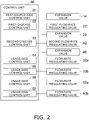
- the control unit 60 includes the heat-source-side control unit 61, the first cascade control unit 62, a second cascade control unit 63, and usage-side control units 64, 65, 66, and 67.
- Each of the control units 60, 61, 62, 63, 64, 65, 66, and 67 includes a processor, such as a CPU or a GPU, a memory, and the like.
- the processor is capable of reading a program stored in the memory and performing predetermined processing in accordance with the program.
- the heat-source-side control unit 61 is disposed at the heat-source-side unit 10.
- the heat-source-side control unit 61 controls the entirety of the heat-source-side unit 10 and the opening degree of the expansion valve 14.
- the first cascade control unit 62 is disposed at the first cascade unit 20.
- the first cascade control unit 62 controls the entirety of the first cascade unit 20 and the opening degrees of the first flow-rate regulating valve 22 and the expansion valve 26.
- the second cascade control unit 63 is disposed at the second cascade unit 40.
- the second cascade control unit 63 controls the entirety of the second cascade unit 40 and the opening degrees of a second flow-rate regulating valve 42 and an expansion valve 46.
- the usage-side control unit 64 is disposed at the usage-side unit 30A.
- the usage-side control unit 64 controls the entirety of the usage-side unit 30A and the opening degree of the flow-rate regulating valve 32a.
- the usage-side control unit 65 is disposed at the usage-side unit 30B.
- the usage-side control unit 65 controls the entirety of the usage-side unit 30B and the opening degree of a flow-rate regulating valve 32b.
- the usage-side control unit 66 is disposed at the usage-side unit 50A.
- the usage-side control unit 66 controls the entirety of the usage-side unit 50A and the opening degree of a flow-rate regulating valve 52a.
- the usage-side control unit 67 is disposed at the usage-side unit 50B.
- the usage-side control unit 67 controls the entirety of the usage-side unit 50B and the opening degree of a flow-rate regulating valve 52b.
- the control unit 60 and the control units 61, 62, 63, 64, 65, 66, and 67 each include a control board on which electric components, such as a microcomputer and a memory, are mounted.
- the control unit 60 controls the entirety of the air conditioning apparatus 100 via the control units 61, 62, 63, 64, 65, 66, and 67.
- the control unit 60 is capable of receiving values detected by each of the sensors provided at the air conditioning apparatus 100 via the control units and sending control signals and the like to each constituent device.
- control unit 60 receives via the first cascade control unit 62 an inlet temperature that is detected by the inlet temperature sensor 23a provided at the first cascade unit 20 and an outlet temperature that is detected by the outlet temperature sensor 23b.
- the control unit 60 is in advance provided with opening-degree regulating algorithm for regulating the opening degree of the first flow-rate regulating valve 22.
- the control unit 60 uses the opening-degree regulating algorithm and generates from the inlet temperature and the outlet temperature a control signal for causing the first refrigerant that exits the first sub heat exchanging unit 21b to have an appropriate degree of superheating.
- the first flow-rate regulating valve 22 is capable of causing the first refrigerant that exits the first sub heat exchanging unit 21b to have an appropriate degree of superheating by regulating the opening degree of the first flow-rate regulating valve 22 on the basis of the control signal.
- the control unit 60 receives via the second cascade control unit 63 an inlet temperature that is detected by an inlet temperature sensor 43a of the second cascade unit 40 and an outlet temperature that is detected by an outlet temperature sensor 43b.
- the control unit 60 uses the opening-degree regulating algorithm and sends a control signal that regulates the opening degree of the second flow-rate regulating valve 42 to the second flow-rate regulating valve 42.
- the second flow-rate regulating valve 42 regulates the opening degree on the basis of the control signal.
- a method by which the control unit 60 regulates the opening degree of the first flow-rate regulating valve 22 or the second flow-rate regulating valve 42 is not limited thereto.
- the basic operation of the air conditioning apparatus 100 includes cooling operation and heating operation.
- the basic operation of the air conditioning apparatus 100 described below is performed by the control unit 60 that controls constituent devices of the air conditioning apparatus 100 (the heat-source-side unit 10, the usage-side units 30A, 30B, 50A, and 50B, the first cascade unit 20, and the second cascade unit 40).
- the switching mechanisms 13, 25, and 45 are switched to a cooling operation state (the state indicated by the solid lines in Fig. 1 ).
- the first refrigerant discharged from the compressor 11 and having a high pressure is sent to the heat-source-side heat exchanger 12 through the switching mechanism 13 in the first refrigerant circuit 1.
- the first refrigerant sent to the heat-source-side heat exchanger 12 condenses by exchanging heat with outdoor air supplied by the heat-source-side fan and being cooled.
- the first refrigerant flows out from the heat-source-side unit 10 through the expansion valve 14.
- the first refrigerant that has flowed out from the heat-source-side unit 10 is sent to the first cascade unit 20 or the second cascade unit 40.
- the first refrigerant sent to the first cascade unit 20 flows into the first cascade heat exchanger 21.
- the first refrigerant sent to the first cascade heat exchanger 21 evaporates by exchanging heat with the second refrigerant that flows in the second refrigerant circuit 2 and being heated. An appropriate degree of superheating has been given to the first refrigerant that has exited the first sub heat exchanging unit 21b.
- the first refrigerant flows out from the first cascade unit 20 and in a state of merging with the first refrigerant that has flowed out from the second cascade unit 40 is sucked by the compressor 11.
- the first refrigerant sent to the second cascade unit 40 flows into a second cascade heat exchanger 41.
- the first refrigerant sent to the second cascade heat exchanger 41 evaporates by exchanging heat with the third refrigerant that flows in the third refrigerant circuit 3 and being heated.
- An appropriate degree of superheating has been given to the first refrigerant that has exited the second sub heat exchanging unit 41b.
- the first refrigerant flows out from the second cascade unit 40 and is in a state of merging with the first refrigerant that has flowed out from the first cascade unit 20 sucked by the compressor 11.
- the second refrigerant discharged from the compressor 24 and having a high pressure is sent to the first cascade heat exchanger 21 through the switching mechanism 25.
- the second refrigerant sent to the first cascade heat exchanger 21 condenses by exchanging heat with the first refrigerant that flows in the first refrigerant circuit 1 and being cooled.
- the second refrigerant flows out from the first cascade unit 20 through the expansion valve 26.
- the second refrigerant that has flowed out from the first cascade unit 20 is sent to each of the usage-side units 30A and 30B.
- the second refrigerant sent to the usage-side unit 30A evaporates in the usage-side heat exchanger 31a that functions as an evaporator for the second refrigerant by exchanging heat with outdoor air supplied by the usage-side fan.
- the second refrigerant flows out from the usage-side unit 30A and in a state of merging with the second refrigerant that has flowed out from the usage-side unit 30B is suck by the compressor 24.
- the second refrigerant sent to the usage-side unit 30B evaporates in the usage-side heat exchanger 31b that functions as an evaporator for the second refrigerant by exchanging heat with outdoor air supplied by the usage-side fan.
- the second refrigerant flows out from the usage-side unit 30B and in a state of merging with the second refrigerant that has flowed out from the usage-side unit 30A is sucked by the compressor 24.
- the third refrigerant discharged from a compressor 44 and having a high pressure is sent to the second cascade heat exchanger 41 through the switching mechanism 45.
- the third refrigerant sent to the second cascade heat exchanger 41 condenses by exchanging heat with the first refrigerant that flows in the first refrigerant circuit 1 and being cooled.
- the third refrigerant flows out from the second cascade unit 40 through the expansion valve 46.
- the third refrigerant that has flowed out from the second cascade unit 40 is sent to each of the usage-side units 50A and 50B.
- the third refrigerant sent to the usage-side unit 50A evaporates in the usage-side heat exchanger 51a that functions as an evaporator for the third refrigerant by exchanging heat with outdoor air supplied by the usage-side fan.
- the third refrigerant flows out from the usage-side unit 50A and in a state of merging with the third refrigerant that has flowed out from the usage-side unit 50B is sucked by the compressor 44.
- the third refrigerant sent to the usage-side unit 50B evaporates in the usage-side heat exchanger 51b that functions as an evaporator for the third refrigerant by exchanging heat with outdoor air supplied by the usage-side fan.
- the third refrigerant flows out from the usage-side unit 50A and in a state of merging with the third refrigerant that has flowed out from the usage-side unit 50B is sucked by the compressor 44.
- the switching mechanisms 13, 25, and 45 are switched to a heating operation state (the state indicated by the broken lines in Fig. 1 ).
- the first refrigerant discharged from the compressor 11 and having a high pressure flows out from the heat-source-side unit 10 through the switching mechanism 13.
- the first refrigerant that has flowed out from the heat-source-side unit 10 is sent to the first cascade unit 20 or the second cascade unit 40.
- the first refrigerant sent to the first cascade unit 20 condenses by exchanging heat with the second refrigerant that flows in the second refrigerant circuit 2 and being cooled.
- the first refrigerant that has condensed passes through the first flow-rate regulating valve 22 and flows out from the first cascade unit 20.
- the first refrigerant that has flowed out from the first cascade unit 20 is sent to the heat-source-side unit 10.
- the first refrigerant sent to the second cascade unit 40 condenses by exchanging heat with the third refrigerant that flows in the third refrigerant circuit 3 and being cooled.
- the third refrigerant that has condensed passes through the second flow-rate regulating valve 42 and flows out from the first cascade unit 20.
- the first refrigerant that has flowed out from the second cascade unit 40 is sent to the heat-source-side unit 10.
- the first refrigerant sent to the heat-source-side unit 10 is sent to the expansion valve 14.
- the first refrigerant sent to the expansion valve 14 is sent to the heat-source-side heat exchanger 12 after being decompressed by the expansion valve 14.
- the first refrigerant sent to the heat-source-side heat exchanger 12 evaporates by exchanging heat with outdoor air supplied by the heat-source-side fan and being heated.
- the first refrigerant that has evaporated is sucked by the compressor 11 through the switching mechanism 13.
- the second refrigerant discharged from the compressor 24 and having a high pressure flows out from the first cascade unit 20 through the switching mechanism 25.
- the second refrigerant that has flowed out from the first cascade unit 20 is sent to each of the usage-side units 30A and 30B.
- the second refrigerant sent to the usage-side unit 30A condenses by exchanging heat with outdoor air supplied by the usage-side fan.
- the second refrigerant that has condensed passes through the flow-rate regulating valve 32a and flows out from the usage-side unit 30A.
- the second refrigerant that has flowed out from the usage-side unit 30A is sent to the first cascade unit 20.
- the second refrigerant sent to the usage-side unit 30B condenses by exchanging heat with outdoor air supplied by the usage-side fan.
- the second refrigerant that has condensed passes through the flow-rate regulating valve 32b and flows out from the usage-side unit 30B.
- the second refrigerant that has flowed out from the usage-side unit 30B is sent to the first cascade unit 20.
- the second refrigerant that has flowed into the first cascade unit 20 flows into the expansion valve 26.
- the second refrigerant that has flowed into the expansion valve 26 is sent to the first cascade heat exchanger 21 after being decompressed by the expansion valve 26.
- the second refrigerant that has flowed into the first cascade heat exchanger 21 evaporates by exchanging heat with the first refrigerant that flows in the first refrigerant circuit 1 and being heated.
- the second refrigerant that has evaporated is sucked by the compressor 24 through the switching mechanism 25.
- the third refrigerant discharged from the compressor 44 and having a high pressure flows out from the second cascade unit 40 through the switching mechanism 45.
- the third refrigerant that has flowed out from the second cascade unit 40 is sent to each of the usage-side units 50A and 50B.
- the third refrigerant sent to the usage-side unit 50A condenses by exchanging heat with outdoor air supplied by the usage-side fan.
- the third refrigerant that has condensed passes through the flow-rate regulating valve 52a and flows out from the usage-side unit 50A.
- the third refrigerant that has flowed out from the usage-side unit 50A is sent to the second cascade unit 40.
- the third refrigerant sent to the usage-side unit 50B condenses by exchanging heat with outdoor air supplied by the usage-side fan.
- the third refrigerant that has condensed passes through the flow-rate regulating valve 52b and flows out from the usage-side unit 50B.
- the third refrigerant that has flowed out from the usage-side unit 50B is sent to the second cascade unit 40.
- the third refrigerant that has flowed into the second cascade unit 40 is sent to the expansion valve 46.
- the third refrigerant that has flowed into the expansion valve 46 is sent to the second cascade heat exchanger 41 after being decompressed by the expansion valve 46.
- the third refrigerant that has flowed into the second cascade heat exchanger 41 evaporates by exchanging heat with the first refrigerant that flows in the first refrigerant circuit 1 and being heated.
- the third refrigerant that has evaporated is sucked by the compressor 44 through the switching mechanism 45.
- the first main heat exchanging unit 21a and the second main heat exchanging unit 41a of the air conditioning apparatus 100 are plate heat exchangers.
- the first sub heat exchanging unit 21b and the second sub heat exchanging unit 41b are double pipes. Each heat exchanging unit is not limited thereto.
- first main heat exchanging unit 21a and the second main heat exchanging unit 41a may be heat exchangers each including a plurality of stacked flat pipes.
- the first sub heat exchanging unit 21b and the second sub heat exchanging unit 41b may be heat exchangers each having a structure in contact with a pipe.
- the first main heat exchanging unit 21a has heat exchanging capacity larger than that of the first sub heat exchanging unit 21b.
- the second main heat exchanging unit 41a has heat exchanging capacity larger than that of the second sub heat exchanging unit 41b.
- the heat exchanging capacity of a plate heat exchanger or a heat exchanger including a plurality of stacked flat pipes is generally larger than the heat exchanging capacity of a double pipe or a heat exchanger having a structure in contact with a pipe.
- R32 having high stability of refrigerant and high performance is charged as the first refrigerant, the second refrigerant, and the third refrigerant, respectively.
- the refrigerant cycle system presented in the present disclosure has been described by using the air conditioning apparatus 100 as a specific example of the refrigerant cycle system.
- the form of the refrigerant cycle system is, however, not limited thereto.
- the refrigerant cycle system may be a heat-pump hot water supply apparatus, or the like.
- the air conditioning apparatus 100 as a refrigerant cycle system includes the first refrigerant circuit 1, the second refrigerant circuit 2, and the first cascade heat exchanger 21.
- the first refrigerant circuit 1 is a vapor compression refrigeration cycle.
- the second refrigerant circuit 2 is a vapor compression refrigeration cycle.
- the first cascade heat exchanger 21 exchanges heat between the first refrigerant that flows in the first refrigerant circuit 1 and the second refrigerant that flows in the second refrigerant circuit 2.
- the air conditioning apparatus 100 includes the switching mechanisms 13 and 25.
- the switching mechanisms 13 and 25 are each present in at least either one of the first refrigerant circuit 1 and the second refrigerant circuit 2 and switch a flow path of a refrigerant of the circuit.
- the first cascade heat exchanger 21 includes the first main heat exchanging unit 21a and the first sub heat exchanging unit 21b.
- the first sub heat exchanging unit 21b is configured to cause the first refrigerant that has passed through the first main heat exchanging unit 21a to be in a superheating state.
- the air conditioning apparatus 100 further includes the first flow-rate regulating valve 22 and the control unit 60.
- the first flow-rate regulating valve 22 regulates the amount of the first refrigerant that flows in the first cascade heat exchanger 21 in the first refrigerant circuit 1.
- the control unit 60 regulates the opening degree of the first flow-rate regulating valve 22.
- the control unit 60 regulates the opening degree of the first flow-rate regulating valve 22 to cause the first refrigerant that exits the first sub heat exchanging unit 21b to be in a superheating state.
- a plate heat exchanger or a heat exchanger including a plurality of stacked flat pipes may be used in a dual refrigerant circuit configured by a vapor compression refrigeration cycle.
- These heat exchangers have high heat exchanging capacity and high performance and are also excellent in compact characteristics.
- controlling the degree of superheating of refrigerant in a plate heat exchanger or a heat exchanger including a plurality of stacked flat pipes decreases heat exchanging capacity and increases a pressure loss. Consequently, the performance of the plate heat exchanger or the heat exchanger including the plurality of stacked flat pipes is impaired.
- the air conditioning apparatus 100 it is possible due to the aforementioned configuration to control the superheating state of the first refrigerant in the first sub heat exchanging unit 21b. It is thus possible to control the superheating state of the first refrigerant without impairing the high heat exchanging capacity of the first main heat exchanging unit 21a.
- the first main heat exchanging unit 21a of the air conditioning apparatus 100 has heat exchanging capacity larger than that of the first sub heat exchanging unit 21b.
- the first main heat exchanging unit 21a of the air conditioning apparatus 100 is a plate heat exchanger or a heat exchanger including a plurality of stacked flat pipes.
- the first sub heat exchanging unit 21b is a double pipe or a heat exchanger having a structure in contact with a pipe.
- first sub heat exchanging unit 21b being a double pipe or a heat exchanger having a structure in contact with a pipe, it is possible to provide a cascade heat exchanger that does not impair the compact characteristics of the main heat exchangers.
- first sub heat exchanging unit 21b being a double pipe or a heat exchanger having a structure in contact with a pipe, it is possible to reduce an increase in costs caused by the provision of the first sub heat exchanging unit 21b.
- the air conditioning apparatus 100 further includes the third refrigerant circuit 3 and the second cascade heat exchanger 41.
- the third refrigerant circuit 3 is a vapor compression refrigeration cycle.
- the second cascade heat exchanger 41 exchanges heat between the first refrigerant that flows in the first refrigerant circuit 1 and the third refrigerant that flows in the third refrigerant circuit 3.
- the second cascade heat exchanger 41 includes the second main heat exchanging unit 41a and the second sub heat exchanging unit 42b.
- the second sub heat exchanging unit 42b is configured to cause refrigerant that has passed through the second main heat exchanging unit 41a to be in a superheating state.
- the first cascade heat exchanger 21 and the second cascade heat exchanger 41 are connected in parallel in the first refrigerant circuit 1.
- the air conditioning apparatus 100 is also applicable to a multi-dual refrigerant circuit including a plurality of cascade units. Consequently, the number of connectable usage-side heat exchangers is increased, which increases flexibility in construction of the air conditioning apparatus 100.
- R32 having high stability is charged as the first refrigerant, the second refrigerant, and the third refrigerant, respectively.
- refrigerant other than R32 may be charged in the refrigerant cycle system presented in the present disclosure.
- the first refrigerant be R32 and that the second refrigerant and the third refrigerant be carbon dioxide.
- R32 has high stability of refrigerant and thus is widely used in existing refrigerant cycle systems.
- An existing refrigerant cycle system can be diverted into the refrigerant cycle system presented in the present disclosure.
- Each of the first refrigerant, the second refrigerant, and the third refrigerant charged in the refrigerant cycle system is preferably any one of HFC refrigerant, HFO refrigerant, and natural refrigerant.
- each of the first refrigerant and the second refrigerant is preferably a mixture refrigerant that contains any two or more of HFC refrigerant, HFO refrigerant, natural refrigerant, and CF 3 I.
- the HFC refrigerant is R32, R125, R134a, R143a, R245fa, or the like.
- the HFO refrigerant is R1234yf, R1234zd, R1123, R1132(E), or the like.
- the natural refrigerant is R744, R717, R290, R600a, R1270, or the like.
- an air conditioning apparatus 200 as one embodiment of a refrigerant cycle apparatus is an apparatus that cools and heats a room in a construction, such as a building, by a first refrigerant circuit 201, a second refrigerant circuit 202, and a third refrigerant circuit 203 that are vapor compression refrigeration cycles.
- the air conditioning apparatus 200 mainly includes a heat-source-side unit 210 that belongs to the first refrigerant circuit 201, a plurality of usage-side units 230A and 230B (two in the present embodiment) that belong to the second refrigerant circuit 202, a plurality of usage-side units 250A and 250B (two in the present embodiment) that belong to the third refrigerant circuit 203, a first cascade unit 220 that is disposed between the heat-source-side unit 210 and the usage-side units 230A and 230B, a second cascade unit 240 that is disposed between the heat-source-side unit 210 and the usage-side units 250A and 250B, refrigerant connection pipes 204a, 204b, 205a, 205b, 206a, and 206b, and a control unit 260.
- the first cascade unit 220 and the second cascade unit 240 are connected in parallel to each other in the first refrigerant circuit 201.
- the plurality of usage-side units 230A and 230B are connected in parallel to each other in the second refrigerant circuit 202.
- the plurality of usage-side units 250A and 250B are connected in parallel to each other in the third refrigerant circuit 203.
- the control unit 260 is connected to a control unit of each unit via a transmission line and the like.
- the control unit 260 controls each constituent device included in the air conditioning apparatus 200 and controls the entirety of the air conditioning apparatus 200.
- R32 is charged as a first refrigerant, a second refrigerant, and a third refrigerant in the first refrigerant circuit 201, the second refrigerant circuit 202, and the third refrigerant circuit 203, respectively.
- the usage-side units 230A, 230B, 250A, and 250B are installed inside a room of a building or the like.
- the plurality of usage-side units 230A and 230B constituting part of the second refrigerant circuit 202 are connected to the first cascade unit 220 via a liquid-refrigerant connection pipe 205a and a gas-refrigerant connection pipe 205b that serve as refrigerant connection pipes.
- the plurality of usage-side units 250A and 250B constituting part of the third refrigerant circuit 203 are connected to the second cascade unit 240 via a liquid-refrigerant connection pipe 206a and a gas-refrigerant connection pipe 206b that serve as refrigerant connection pipes.
- the usage-side unit 230A and the usage-side units 230B, 250A, and 250B have the same configuration. Thus, only the configuration of the usage-side unit 230A will be described here, and description of the configurations of the usage-side units 230B, 250A, and 250B is omitted.
- the usage-side unit 230A mainly includes a usage-side heat exchanger 231a and a flow-rate regulating valve 232a. Each constituent device of the usage-side unit 230A is controlled by the control unit 260 via a usage-side control unit 264.
- the usage-side heat exchanger 231a is a heat exchanger that functions as an evaporator for the second refrigerant and cools indoor air or functions as a radiator for the second refrigerant and heats indoor air.
- the usage-side unit 230A includes a usage-side fan, which is not illustrated. The usage-side fan supplies indoor air as a cooling source or a heating source of the second refrigerant that flows in the usage-side heat exchanger 231a to the usage-side heat exchanger 231a.
- the flow-rate regulating valve 232a is an electric expansion valve capable of regulating, while decompressing the second refrigerant, the flow rate of the second refrigerant that flows in the usage-side heat exchanger 231a.
- the opening degree of the flow-rate regulating valve 232a is regulated by the control unit 260 via the usage-side control unit 264.
- the usage-side unit 230A is provided with various types of sensors, which are not illustrated. Values detected by each of the sensors are sent to the control unit 260 via the usage-side control unit 264.
- the heat-source-side unit 210 constituting part of the first refrigerant circuit 201 is installed outside a room of a construction, such as a building, for example, on a rooftop or on the ground.
- the heat-source-side unit 210 is connected to the first cascade unit 220 or the second cascade unit 240 via the liquid-refrigerant connection pipe 204a and the gas-refrigerant connection pipe 204b.
- the heat-source-side unit 210 mainly includes a compressor 211 and a heat-source-side heat exchanger 212.
- the heat-source-side unit 210 includes a switching mechanism 213 as a cooling-heating switching mechanism that switches between a cooling operation state in which the heat-source-side heat exchanger 212 functions as a radiator for refrigerant and a heating operation state in which the heat-source-side heat exchanger 212 functions as an evaporator for refrigerant.
- Each constituent device of the heat-source-side unit 210 is controlled by the control unit 260 via a heat-source-side control unit 261.
- the compressor 211 is a device for compressing the first refrigerant and is, for example, a compressor having a hermetic structure and in which a compression element of a positive-displacement type, such as a rotary type or scroll type, is driven to rotate by a compression motor.
- a compression element of a positive-displacement type such as a rotary type or scroll type
- the heat-source-side heat exchanger 212 is a heat exchanger that functions as a radiator for the first refrigerant or functions as an evaporator for the first refrigerant.
- the heat-source-side unit 210 includes a heat-source-side fan, which is not illustrated.
- the heat-source-side fan takes outdoor air into the heat-source-side unit 210 and discharges the outdoor air to the outside after causing heat to be exchanged between the outdoor air and the first refrigerant in the heat-source-side heat exchanger 212.
- the first refrigerant circuit 201 is provided with an expansion valve 214 near the liquid-side end of the heat-source-side heat exchanger 212.
- the expansion valve 214 is an electric expansion valve that decompresses the first refrigerant in a heating operation state.
- the opening degree of the expansion valve 214 is regulated by the control unit 260 via the heat-source-side control unit 261.
- the heat-source-side unit 210 is provided with various types of sensors, which are not illustrated. Values detected by each of the sensors are sent to the control unit 260 via the heat-source-side control unit 261.
- the first cascade unit 220 and the second cascade unit 240 are installed in a space of, for example, an attic of a room of a construction, such as a building.
- the first cascade unit 220 is interposed between the usage-side units 230A and 230B and the heat-source-side unit 210 and constitutes part of the first refrigerant circuit 201 and part of the second refrigerant circuit 202.
- the second cascade unit 240 is interposed between the usage-side units 250A and 250B and the heat-source-side unit 210 and constitutes part of the first refrigerant circuit 201 and part of the third refrigerant circuit 203.
- the first cascade unit 220 and the second cascade unit 240 have the same configuration. Thus, only the configuration of the first cascade unit 220 will be described here, and description of the configuration of the second cascade unit 240 is omitted.
- the first cascade unit 220 mainly includes a first main heat exchanging unit 221a, a first sub heat exchanging unit 221b, a first flow-rate regulating valve 222, a first bypass circuit 225, a first bypass valve 223, a compressor 226, and an expansion valve 228.
- the first cascade unit 220 includes a switching mechanism 227 that serves as a cooling-heating switching mechanism.
- Each constituent device of the first cascade unit 220 is controlled by the control unit 260 via a first cascade control unit 262.
- the first main heat exchanging unit 221a When functioning as a radiator for the first refrigerant in the first refrigerant circuit 201, the first main heat exchanging unit 221a functions as an evaporator for the second refrigerant in the second refrigerant circuit 202. When functioning as an evaporator for the first refrigerant in the first refrigerant circuit 201, the first main heat exchanging unit 221a functions as a radiator for the second refrigerant in the second refrigerant circuit 202.
- the first main heat exchanging unit 221a is a heat exchanger that exchanges heat between the first refrigerant that flows in the first refrigerant circuit 201 and the second refrigerant that flows in the second refrigerant circuit 202.
- the first sub heat exchanging unit 221b is configured to cause the first refrigerant that has passed through the first main heat exchanging unit 221a to be in a superheating state.
- the superheating state is a state in which a degree of superheating has been given to the first refrigerant. A degree of superheating to be given is not limited as long as some degree of superheating is given.
- the first sub heat exchanging unit 221b exchanges heat between the first refrigerant that has not entered the first main heat exchanging unit 221a yet and the first refrigerant that has exited the first main heat exchanging unit 221a.
- the first bypass valve 223, which will be described later, is fully closed.
- the first refrigerant that has exited the first main heat exchanging unit 221a flows out from the first cascade unit 220 via the first bypass circuit 225, which will be described later.
- the first sub heat exchanging unit 221b thus does not exchange heat.
- the first main heat exchanging unit 221a is a heat exchanger having heat exchanging capacity larger than that of the first sub heat exchanging unit 221b.
- the first main heat exchanging unit 221a is a plate heat exchanger
- the first sub heat exchanging unit 221b is a double pipe.
- the heat exchanging capacity of a heat exchanger can be calculated by a heat transfer rate and the like.
- the heat exchanging capacity of a plate heat exchanger used as the first main heat exchanging unit 221a is generally larger than the heat exchanging capacity of a double pipe used as the first sub heat exchanging unit 221b.
- a method of calculating the heat exchanging capacity of a heat exchanger is not limited.
- the first refrigerant circuit 201 is provided with the first flow-rate regulating valve 222 near the liquid-side end of the first main heat exchanging unit 221a.
- the first flow-rate regulating valve 222 is an electric expansion valve that decompresses the first refrigerant in a cooling operation state.
- the valve opening degree of the first flow-rate regulating valve 222 is regulated by the control unit 260 via the first cascade control unit 262 to cause the first refrigerant that exits the first sub heat exchanging unit 221b to be in a superheating state.
- the first bypass circuit 225 is, for example, a capillary.
- the first refrigerant that has exited the first main heat exchanging unit 221a bypasses the first sub heat exchanging unit 221b via the first bypass circuit 225.
- the first refrigerant that has bypassed the first sub heat exchanging unit 221b flows out from the first cascade unit 220.
- the first bypass valve 223 is provided on the upstream side of the first sub heat exchanging unit 221b.
- the first bypass valve 223 is fully closed in a heating operation state. Consequently, the first refrigerant that has exited the first main heat exchanging unit 221a flows out from the first cascade unit 220 via the first bypass circuit 225, and the first sub heat exchanging unit 221b does not exchange heat.
- the first bypass valve 223 is an electric expansion valve, and the valve opening degree of the first bypass valve 223 is regulated by the control unit 260 via the first cascade control unit 262.
- the compressor 226 is a device for compressing the second refrigerant.
- a compressor having a hermetic structure and in which a compression element of a positive displacement type, such as a rotary type or scroll type, is driven to rotate by a compression motor is used.
- the second refrigerant circuit 202 is provided with the expansion valve 228 near the liquid-side end of the first main heat exchanging unit 221a.
- the expansion valve 228 is an electric expansion valve that decompresses refrigerant in a heating operation state.
- the opening degree of the expansion valve 228 is regulated by the control unit 260 via the first cascade control unit 262.
- the first cascade unit 220 is further provided with an inlet temperature sensor 224a and an outlet temperature sensor 224b.
- the inlet temperature sensor 224a detects a temperature (inlet temperature) of the first refrigerant at the liquid-side end of the first main heat exchanging unit 221a in the first refrigerant circuit 201.
- the outlet temperature sensor 224b detects a temperature (outlet temperature) of the first refrigerant at the gas-side end of the first sub heat exchanging unit 221b in the first refrigerant circuit 201. Values detected by the inlet temperature sensor 224a and the outlet temperature sensor 224b are sent to the control unit 260 via the first cascade control unit 262.
- the first cascade unit 220 is also provided with various types of sensors, which are not illustrated, other than the aforementioned sensors.
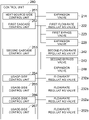
- the control unit 260 includes the heat-source-side control unit 261, the first cascade control unit 262, a 2second cascade control unit 263, and usage-side control units 264, 265, 266, and 267.
- Each of the control units 260, 261, 262, 263, 264, 265, 266, and 267 includes a processor, such as a CPU or a GPU, a memory, and the like.
- the processor is capable of reading a program stored in the memory and performing predetermined processing in accordance with the program.
- the heat-source-side control unit 261 is disposed at the heat-source-side unit 210.
- the heat-source-side control unit 261 controls the entirety of the heat-source-side unit 210 and the opening degree of the expansion valve 214.
- the first cascade control unit 262 is disposed at the first cascade unit 220.
- the first cascade control unit 262 controls the entirety of the first cascade unit 220 and the opening degrees of the first flow-rate regulating valve 222, the first bypass valve 223, and the expansion valve 228.
- the second cascade control unit 263 is disposed at the second cascade unit 240.
- the second cascade control unit 263 controls the entirety of the second cascade unit 240 and the opening degrees of a second flow-rate regulating valve 242, a second bypass valve 243, and an expansion valve 248.
- the usage-side control unit 264 is disposed at the usage-side unit 230A.
- the usage-side control unit 264 controls the entirety of the usage-side unit 230A and the opening degree of the flow-rate regulating valve 232a.
- the usage-side control unit 265 is disposed at the usage-side unit 230B.
- the usage-side control unit 265 controls the entirety of the usage-side unit 230B and the opening degree of a flow-rate regulating valve 232b.
- the usage-side control unit 266 is disposed at the usage-side unit 250A.
- the usage-side control unit 266 controls the entirety of the usage-side unit 250A and the opening degree of a flow-rate regulating valve 252a.
- the usage-side control unit 267 is disposed at the usage-side unit 250B.
- the usage-side control unit 267 controls the entirety of the usage-side unit 250B and the opening degree of a flow-rate regulating valve 252b.
- the control unit 260 and the control units 261, 262, 263, 264, 265, 266, and 267 each include a control board on which electric components, such as a microcomputer and a memory, are mounted.
- the control unit 260 controls the entirety of the air conditioning apparatus 200 via the control units 261, 262, 263, 264, 265, 266, and 267.
- the control unit 260 is capable of receiving values detected by the sensors provided at the air conditioning apparatus 200 via the control units 261, 262, 263, 264, 265, 266, and 267 and sending control signals and the like to each constituent device.
- the control unit 260 receives via the first cascade control unit 262 an inlet temperature that is detected by the inlet temperature sensor 224a provided at the first cascade unit 220 and an outlet temperature that is detected by the outlet temperature sensor 224b.
- the control unit 260 is in advance provided with opening-degree regulating algorithm for regulating the opening degree of the first flow-rate regulating valve 222.
- the control unit 260 uses the opening-degree regulating algorithm and generates from the inlet temperature and the outlet temperature a control signal for causing the first refrigerant that exits the first sub heat exchanging unit 221b to have an appropriate degree of superheating.
- the first flow-rate regulating valve 222 is capable of causing the first refrigerant that exits the first sub heat exchanging unit 221b to have an appropriate degree of superheating by regulating the opening degree of the first flow-rate regulating valve 222 on the basis of the control signal.
- the control unit 260 receives via the second cascade control unit 263 an inlet temperature that is detected by an inlet temperature sensor 244a of the second cascade unit 240 and an outlet temperature that is detected by an outlet temperature sensor 244b.
- the control unit 260 uses the opening-degree regulating algorithm and sends a control signal that regulates the opening degree of the second flow-rate regulating valve 242 to the second flow-rate regulating valve 242.
- the second flow-rate regulating valve 242 regulates the opening degree on the basis of the control signal.
- a method by which the control unit 260 regulates the opening degree of the first flow-rate regulating valve 222 or the second flow-rate regulating valve 242 is not limited thereto.
- the basic operation of the air conditioning apparatus 200 includes cooling operation and heating operation.
- the basic operation of the air conditioning apparatus 200 described below is performed by the control unit 260 that controls constituent devices of the air conditioning apparatus 200 (the heat-source-side unit 210, the usage-side units 230A, 230B, 250A, and 250B, the first cascade unit 220, and the second cascade unit 240).
- the switching mechanisms 213, 227, and 247 are switched to a cooling operation state (the state indicated by the solid lines in Fig. 3 ).
- the first refrigerant discharged from the compressor 211 and having a high pressure is sent to the heat-source-side heat exchanger 212 through the switching mechanism 213 in the first refrigerant circuit 201.
- the first refrigerant sent to the heat-source-side heat exchanger 212 condenses in the heat-source-side heat exchanger 212 that functions as a radiator for the first refrigerant by exchanging heat with outdoor air supplied by the heat-source-side fan and being cooled.
- the first refrigerant flows out from the heat-source-side unit 210 through the expansion valve 214.
- the first refrigerant that has flowed out from the heat-source-side unit 210 is sent to the first cascade unit 220 and the second cascade unit 240.
- the first refrigerant that has flowed into the first cascade unit 220 enters the first sub heat exchanging unit 221b.
- the first refrigerant that has entered the first sub heat exchanging unit 221b exchanges heat with the first refrigerant that has exited the first main heat exchanging unit 221a.
- the first refrigerant exits the first sub heat exchanging unit 221b and passes through the first bypass valve 223.
- the first refrigerant then enters the first flow-rate regulating valve 222 whose opening degree is appropriately regulated by the control unit 260 and is decompressed.
- the decompressed first refrigerant enters the first main heat exchanging unit 221a.
- the first refrigerant evaporates by exchanging heat with the second refrigerant that flows in the second refrigerant circuit 202 and being heated.
- the first refrigerant that has exited the first sub heat exchanging unit 221b enters the first sub heat exchanging unit 221b and exchanges heat with the first refrigerant that has not entered the first main heat exchanging unit 221a yet.
- An appropriate degree of superheating has been given to the first refrigerant that has exchanged heat here and exited the first sub heat exchanging unit 221b.
- the first refrigerant flows out from the first cascade unit 220 and is sucked in a state of merging with the first refrigerant that has flowed out from the second cascade unit 240 by the compressor 211.
- the first refrigerant that has flowed into the second cascade unit 240 enters a second sub heat exchanging unit 241b.
- the first refrigerant that has entered the second sub heat exchanging unit 241b exchanges heat with the first refrigerant that has exited a second main heat exchanging unit 241a.
- the first refrigerant exits the second sub heat exchanging unit 241b and passes through the second bypass valve 243.
- the first refrigerant then enters the second flow-rate regulating valve 242 whose opening degree is appropriately regulated by the control unit 260 and is decompressed.
- the decompressed first refrigerant enters a second heat exchanger 241.
- the first refrigerant that has entered the second heat exchanger 241 evaporates in the second main heat exchanging unit 241a that functions as an evaporator for the first refrigerant by exchanging heat with the third refrigerant that flows in the third refrigerant circuit 203 and being heated.
- the first refrigerant that has exited the second sub heat exchanging unit 241b enters the second sub heat exchanging unit 241b and exchanges heat with the first refrigerant that has not entered the second main heat exchanging unit 241a yet.
- An appropriate degree of superheating has been given to the first refrigerant that has exchanged heat here and exited the second sub heat exchanging unit 241b.
- the first refrigerant flows out from the second cascade unit 240 and in a state of merging with the first refrigerant that has flowed out from the first cascade unit 220 is sucked by the compressor 211.
- the second refrigerant discharged from the compressor 226 and having a high pressure is sent to the first main heat exchanging unit 221a through the switching mechanism 227 in the second refrigerant circuit 202.
- the first main heat exchanging unit 221a that functions as a radiator for the second refrigerant
- the second refrigerant condenses by exchanging heat with the first refrigerant that flows in the first refrigerant circuit 201 and being cooled.
- the second refrigerant flows out from the first cascade unit 220 through the expansion valve 228.
- the second refrigerant that has flowed out from the first cascade unit 220 is sent to each of the usage-side units 230A and 230B.
- the second refrigerant sent to the usage-side unit 230A evaporates in the usage-side heat exchanger 231a that functions as an evaporator for the second refrigerant by exchanging heat with outdoor air supplied by the usage-side fan.
- the second refrigerant flows out from the usage-side unit 230A and in a state of merging with the second refrigerant that has flowed out from the usage-side unit 230B is sucked by the compressor 226.
- the second refrigerant sent to the usage-side unit 230B evaporates in the usage-side heat exchanger 231b that functions as an evaporator for the second refrigerant by exchanging heat with outdoor air supplied by the usage-side fan.
- the second refrigerant flows out from the usage-side unit 230B and is in a state of merging with the second refrigerant that has flowed out from the usage-side unit 230A sucked by the compressor 226.
- Indoor air cooled in the usage-side heat exchangers 231a and 231b is sent to the inside of a room, thereby cooling the inside of the room.
- the third refrigerant discharged from a compressor 244 and having a high pressure is sent to the second main heat exchanging unit 241a through the switching mechanism 247.
- the third refrigerant sent to the second main heat exchanging unit 241a condenses in the second main heat exchanging unit 241a that functions as a radiator for the third refrigerant by exchanging heat with the first refrigerant that flows in the first refrigerant circuit 201 and being cooled.
- the third refrigerant flows out from the second cascade unit 240 through an expansion valve 246.
- the third refrigerant that has flowed out from the second cascade unit 240 is sent to each of the usage-side units 250A and 250B.
- the third refrigerant sent to the usage-side unit 250A evaporates in the usage-side heat exchanger 251a that functions as an evaporator for the third refrigerant by exchanging heat with outdoor air supplied by the usage-side fan.
- the third refrigerant flows out from the usage-side unit 250A and in a state of merging with the third refrigerant that has flowed out from the usage-side unit 250B is sucked by the compressor 244.
- the third refrigerant sent to the usage-side unit 250B evaporates in the usage-side heat exchanger 251b that functions as an evaporator for the third refrigerant by exchanging heat with outdoor air supplied by the usage-side fan.
- the third refrigerant flows out from the usage-side unit 250A and in a state of merging with the third refrigerant that has flowed out from the usage-side unit 250B is sucked by the compressor 244.
- the switching mechanisms 213, 227, and 247 are switched to a heating operation state (the state indicated by the broken lines in Fig. 3 ).
- the first refrigerant discharged from the compressor 211 and having a high pressure flows out from the heat-source-side unit 210 through the switching mechanism 213.
- the first refrigerant that has flowed out from the heat-source-side unit 210 is sent to the first cascade unit 220 and the second cascade unit 240.
- the first refrigerant sent to the first cascade unit 220 passes through the first sub heat exchanging unit 221b and enters the first main heat exchanging unit 221a. At this time, the first refrigerant does not exchange heat in the first sub heat exchanging unit 221b.
- the first refrigerant that has entered the first main heat exchanging unit 221a condenses by exchanging heat with the second refrigerant that flows in the second refrigerant circuit 202 and being cooled.
- the first refrigerant that has condensed passes through the first flow-rate regulating valve 222.
- the first bypass valve 223 has an opening degree regulated by the control unit 260 and is in a fully closed state.
- the first refrigerant that has passed through the first flow-rate regulating valve 222 bypasses the first sub heat exchanging unit 221b via the first bypass circuit 225.
- the first refrigerant flows out from the first cascade unit 220.
- the first refrigerant that has flowed out from the first cascade unit 220 is sent to the heat-source-side unit 210.
- the first refrigerant sent to the second cascade unit 240 passes through the second sub heat exchanging unit 241b and enters the second main heat exchanging unit 241a. At this time, the first refrigerant does not exchange heat in the second sub heat exchanging unit 241b.
- the first refrigerant that has entered the second main heat exchanging unit 241a condenses by exchanging heat with the third refrigerant that flows in the third refrigerant circuit 203 and being cooled.
- the first refrigerant that has condensed passes through the second flow-rate regulating valve 242.
- the second bypass valve 243 has an opening degree regulated by the control unit 260 and is in a fully closed state.
- the first refrigerant that has passed through the second flow-rate regulating valve 242 bypasses the second sub heat exchanging unit 241b via a second bypass circuit 245.
- the first refrigerant flows out from the second cascade unit 240.
- the first refrigerant that has flowed out from the second cascade unit 240 is sent to the heat-source-side unit 210.
- the first refrigerant sent to the heat-source-side unit 210 is sent to the expansion valve 214.
- the first refrigerant sent to the expansion valve 214 is sent to the heat-source-side heat exchanger 212.
- the first refrigerant that has entered the heat-source-side heat exchanger 212 evaporates by exchanging heat with outdoor air supplied by the heat-source-side fan and being heated.
- the first refrigerant that has evaporated is sucked by the compressor 211 through the switching mechanism 213.
- the second refrigerant discharged from the compressor 226 and having a high pressure flows out from the first cascade unit 220 through the switching mechanism 227.
- the second refrigerant that has flowed out from the first cascade unit 220 is sent to each of the usage-side units 230A and 230B.
- the second refrigerant sent to the usage-side unit 230A condenses in the usage-side heat exchanger 231a that functions as a radiator for refrigerant by exchanging heat with outdoor air supplied by the usage-side fan.
- the second refrigerant that has condensed passes through the flow-rate regulating valve 232a and flows out from the usage-side unit 230A.
- the second refrigerant that has flowed out from the usage-side unit 230A is sent to the first cascade unit 220.
- the second refrigerant sent to the usage-side unit 230B condenses in the usage-side heat exchanger 231b that functions as a radiator for refrigerant by exchanging heat with outdoor air supplied by the usage-side fan.
- the second refrigerant that has condensed passes through the flow-rate regulating valve 232b and flows out from the usage-side unit 230B.
- the second refrigerant that has flowed out from the usage-side unit 230B is sent to the first cascade unit 220.
- Indoor air heated in the usage-side heat exchangers 231a and 231b is sent to the inside of a room, thereby heating the inside of the room.
- the second refrigerant that has flowed into the first cascade unit 220 flows into the expansion valve 228.
- the second refrigerant that has flowed into the expansion valve 228 is sent to the first main heat exchanging unit 221a after being decompressed by the expansion valve 228.
- the first main heat exchanging unit 221a that functions as an evaporator for the second refrigerant the second refrigerant evaporates by exchanging heat with the first refrigerant that flows in the first refrigerant circuit 201 and being heated.
- the second refrigerant that has evaporated is sucked by the compressor 226 through the switching mechanism 227.
- the third refrigerant discharged from the compressor 244 and having a high pressure flows out from the second cascade unit 240 through the switching mechanism 247.
- the third refrigerant that has flowed out from the second cascade unit 240 is sent to each of the usage-side units 250A and 250B.
- the third refrigerant sent to the usage-side unit 250A condenses in the usage-side heat exchanger 251a that functions as a radiator for refrigerant by exchanging heat with outdoor air supplied by the usage-side fan.
- the third refrigerant that has condensed passes through the flow-rate regulating valve 252a and flows out from the usage-side unit 250A.
- the third refrigerant that has flowed out from the usage-side unit 250A is sent to the second cascade unit 240.
- the third refrigerant sent to the usage-side unit 250B condenses in the usage-side heat exchanger 251b that functions as a radiator for refrigerant by exchanging heat with outdoor air supplied by the usage-side fan.
- the third refrigerant that has condensed passes through the flow-rate regulating valve 252b and flows out from the usage-side unit 250B.
- the third refrigerant that has flowed out from the usage-side unit 250B is sent to the second cascade unit 240.
- Indoor air heated in the usage-side heat exchangers 251a and 251b is sent to the inside of a room, thereby heating the inside of the room.
- the third refrigerant that has flowed into the second cascade unit 240 is sent to the expansion valve 246.
- the third refrigerant that has flowed into the expansion valve 246 is sent to the second main heat exchanging unit 241a after being decompressed by the expansion valve 246.
- the third refrigerant that has flowed into the second main heat exchanging unit 241a evaporates in the second main heat exchanging unit 241a that functions as an evaporator for the third refrigerant by exchanging heat with the first refrigerant that flows in the first refrigerant circuit 201 and being heated.
- the third refrigerant that has evaporated is sucked by the compressor 244 through the switching mechanism 247.
- the first main heat exchanging unit 221a and the second main heat exchanging unit 241a of the air conditioning apparatus 200 are plate heat exchangers, and the first sub heat exchanging unit 221b and the second sub heat exchanging unit 241b are double pipes. Each heat exchanging unit is not limited thereto.
- first main heat exchanging unit 221a and the second main heat exchanging unit 241a may be heat exchangers each including a plurality of stacked flat pipes
- first sub heat exchanging unit 221b and the second sub heat exchanging unit 241b may be heat exchangers each having a structure in contact with a pipe.
- the first main heat exchanging unit 221a is at least a heat exchanger having heat exchanging capacity larger than that of the first sub heat exchanging unit 221b.
- the second main heat exchanging unit 241a is at least a heat exchanger having heat exchanging capacity larger than that of the second sub heat exchanging unit 241b.
- the heat exchanging capacity of a plate heat exchanger or a heat exchanger including a plurality of stacked flat pipes is generally larger than the heat exchanging capacity of a double pipe or a heat exchanger having a structure in contact with a pipe.
- the first cascade unit 220 of the air conditioning apparatus 200 is provided with the inlet temperature sensor 224a at the liquid-side end of the first main heat exchanging unit 221a and provided with the outlet temperature sensor 224b at the gas-side end of the first sub heat exchanging unit 221b.
- Arrangements of the inlet temperature sensor and the outlet temperature sensor are, however, not limited thereto.
- the outlet temperature sensor 224b may be provided at an outlet of the first main heat exchanging unit 221a.
- the first bypass circuit 225 and the second bypass circuit 245 of the air conditioning apparatus 200 are capillaries.
- the forms of the first bypass circuit 225 and the second bypass circuit 245 are, however, not limited thereto.
- the first bypass circuit 225 and the second bypass circuit 245 may be electric expansion valves, electric on-off valves, or check valves.
- the first bypass valve 223 and the second bypass valve 243 are electric expansion valves. Forms of the first bypass valve 223 and the second bypass valve 243 are, however, not limited thereto.
- the first bypass valve 223 and the second bypass valve 243 may be electric on-off valves or check valves.
- R32 having high stability is charged as the first refrigerant, the second refrigerant, and the third refrigerant, respectively.
- refrigerant other than R32 may be charged in the refrigerant cycle system presented in the present disclosure.
- the first refrigerant be R32 and that the second refrigerant and the third refrigerant be carbon dioxide.
- Each of the first refrigerant, the second refrigerant, and the third refrigerant charged in the refrigerant cycle system is preferably any one of HFC refrigerant, HFO refrigerant, and a natural refrigerant.
- each of the first refrigerant and the second refrigerant is preferably a mixture refrigerant that contains any two or more of HFC refrigerant, HFO refrigerant, natural refrigerant, and CF 3 I.
- the HFC refrigerant is R32, R125, R134a, R143a, R245fa, or the like.
- the HFO refrigerant is R1234yf, R1234zd, R1123, R1132(E), or the like.
- the natural refrigerant is R744, R717, R290, R600a, R1270, or the like.
- the refrigerant cycle system presented in the present disclosure has been described by using the air conditioning apparatus 200 as a specific example of the refrigerant cycle system.
- the form of the refrigerant cycle system is, however, not limited thereto.
- the refrigerant cycle system may be a heat-pump hot water supply apparatus, or the like.
- the air conditioning apparatus 200 as the refrigerant cycle system presented in the present disclosure includes the first refrigerant circuit 201, the second refrigerant circuit 202, the third refrigerant circuit 203, the first main heat exchanging unit 221a, the second main heat exchanging unit 241a, the first flow-rate regulating valve 222, and the second flow-rate regulating valve 242.
- the first refrigerant circuit 201 is a vapor compression refrigeration cycle.
- the second refrigerant circuit 202 is a vapor compression refrigeration cycle.
- the third refrigerant circuit 203 is a vapor compression refrigeration cycle.
- the first main heat exchanging unit 221a exchanges heat between the first refrigerant and the second refrigerant.
- the first refrigerant is refrigerant that flows in the first refrigerant circuit 201.
- the second refrigerant is refrigerant that flows in the second refrigerant circuit 202.
- the second main heat exchanging unit 241a exchanges heat between the first refrigerant and the third refrigerant.
- the third refrigerant is refrigerant that flows in the third refrigerant circuit 203.
- the first flow-rate regulating valve 222 regulates the amount of the first refrigerant that enters the first main heat exchanging unit 221a in the first refrigerant circuit 201.
- the second flow-rate regulating valve 242 regulates the amount of the first refrigerant that enters the second main heat exchanging unit 241a in the first refrigerant circuit 201.
- the first main heat exchanging unit 221a and the second main heat exchanging unit 241a are connected in parallel in the first refrigerant circuit 201.
- a dual refrigeration cycle to which a vapor compression refrigeration cycle is connected via a cascade heat exchanger is known in the art. It is preferable in the dual refrigeration cycle that a large number of usage-side units be connectable to one heat source unit, for example, when an air conditioner is constructed in large-scale commercial facility or a construction, such as a building. Consequently, it is possible to reduce a space and costs required for the installation of the air conditioner.
- the second refrigerant circuit 202 including the first main heat exchanging unit 221a and the third refrigerant circuit 203 including the second main heat exchanging unit 241a are connected in parallel. Consequently, it is possible to connect a larger number of usage units with respect to one heat source unit.
- the air conditioning apparatus 200 further includes the control unit 260.
- the control unit 260 regulates the opening degrees of the first flow-rate regulating valve 222 and the second flow-rate regulating valve 242.
- the control unit 260 regulates the opening degree of the first flow-rate regulating valve 222 to cause the first refrigerant that exits the first main heat exchanging unit 221a to be in a superheating state.
- the control unit 260 regulates the opening degree of the second flow-rate regulating valve 242 to cause the first refrigerant that exits a second main heat exchanging unit 242a to be in a superheating state.
- the control unit 260 is capable of regulating the opening degrees of the first flow-rate regulating valve 222 and the second flow-rate regulating valve 242. Consequently, the control unit 260 is capable of controlling the degree of superheating of the first refrigerant that exits the first main heat exchanging unit 221a or the second main heat exchanging unit 242a and capable of driving the air conditioning apparatus 200 efficiently.
- the air conditioning apparatus 200 further includes the first sub heat exchanging unit 221b.
- the first sub heat exchanging unit 221b exchanges heat in the first refrigerant circuit 201 between the first refrigerant that has not entered the first main heat exchanging unit 221a yet and the first refrigerant that has exited the first main heat exchanging unit 221a.
- the first refrigerant circuit 201 of the air conditioning apparatus 200 further includes the first bypass circuit 225.
- the first refrigerant circuit 201 when the first main heat exchanging unit 221a serves as a condenser, the first refrigerant that has exited the first main heat exchanging unit 221a bypasses the first sub heat exchanging unit 221b via the first bypass circuit 225.
- the first refrigerant that has bypassed the first sub heat exchanging unit 221b is sucked by the compressor 211 included in the first refrigerant circuit 201.
- the first main heat exchanging unit 221a of the air conditioning apparatus 200 has heat exchanging capacity larger than that of the first sub heat exchanging unit 221b.
- the first sub heat exchanging unit 221b included in the air conditioning apparatus 200 Due to the first sub heat exchanging unit 221b included in the air conditioning apparatus 200, it is possible to reduce a decrease in the heat exchanging capacity of the first main heat exchanging unit 221a caused by control of the degree of superheating of the first refrigerant.
- the first bypass circuit 225 included in the air conditioning apparatus 200 enables the first refrigerant to bypass the first sub heat exchanging unit 221b when the first refrigerant circuit 201 performs heating operation.
- the first main heat exchanging unit 221a is preferably a high-performance heat exchanger having large heat exchanging capacity.
- the first sub heat exchanging unit 221b is a heat exchanger capable of giving a degree of superheating to the first refrigerant without impairing the heat exchanging capacity of the first main heat exchanging unit 221a.
- the air conditioning apparatus 200 further includes the second sub heat exchanging unit 241b.
- the second sub heat exchanging unit 241b exchanges heat in the second refrigerant circuit 202 between the first refrigerant that has not entered the second main heat exchanging unit 241a yet and the first refrigerant that has exited the second main heat exchanging unit 241a.
- the first refrigerant circuit 201 further includes the second bypass circuit 245.
- the first refrigerant circuit 201 when the second main heat exchanging unit 241a serves as a condenser, the first refrigerant that has exited the second main heat exchanging unit 241a bypasses the second sub heat exchanging unit 241b via the second bypass circuit 245.
- the first refrigerant that has bypassed the second sub heat exchanging unit 241b is sucked by the compressor 211 included in the first refrigerant circuit 201.
- the second main heat exchanging unit 241a of the air conditioning apparatus 200 has heat exchanging capacity larger than that of the second sub heat exchanging unit 241b.
- R32 having high stability is charged as the first refrigerant, the second refrigerant, and the third refrigerant, respectively.
- refrigerant other than R32 may be charged in the refrigerant cycle system presented in the present disclosure.
- the first refrigerant be R32 and that the second refrigerant and the third refrigerant be carbon dioxide.
- Each of the first refrigerant, the second refrigerant, and the third refrigerant charged in the refrigerant cycle system is preferably any one of HFC refrigerant, HFO refrigerant, and natural refrigerant.
- each of the first refrigerant and the second refrigerant is preferably a mixture refrigerant that contains any two or more of HFC refrigerant, HFO refrigerant, natural refrigerant, and CF 3 I.
- the aforementioned refrigerants can be employed as refrigerant charged in the air conditioning apparatus 200 according to the present embodiment.
Landscapes
- Engineering & Computer Science (AREA)
- Physics & Mathematics (AREA)
- Mechanical Engineering (AREA)
- Thermal Sciences (AREA)
- General Engineering & Computer Science (AREA)
- Compression-Type Refrigeration Machines With Reversible Cycles (AREA)
- Air Conditioning Control Device (AREA)
Abstract
Description
- The present disclosure relates to a refrigerant cycle system.
- As described in PTL 1 (
Japanese Unexamined Patent Application Publication No. 2000-193339 - Control of a state of refrigerant in the dual refrigerant circuit is not mentioned in PTL 1.
- A refrigerant cycle system according to a first aspect includes a first refrigerant circuit, a second refrigerant circuit, and a first cascade heat exchanger. The first refrigerant circuit is a vapor compression refrigeration cycle. The second refrigerant circuit is a vapor compression refrigeration cycle. The first cascade heat exchanger exchanges heat between a first refrigerant that flows in the first refrigerant circuit and a second refrigerant that flows in the second refrigerant circuit. The refrigerant cycle system includes a switching mechanism. The switching mechanism switches a flow path of a refrigerant of at least either one of the first refrigerant circuit and the second refrigerant circuit. The first cascade heat exchanger includes a first main heat exchanging unit and a first sub heat exchanging unit. The first refrigerant that has passed through the first main heat exchanging unit passes through the first sub heat exchanging unit.
- Consequently, it is possible to control the superheating state of the first refrigerant in the first sub heat exchanging unit. The superheating state of the first refrigerant is thus controlled easily.
- A refrigerant cycle system according to a second aspect is the system according to the first aspect further including a first flow-rate regulating valve and a control unit. The first flow-rate regulating valve regulates the amount of the first refrigerant that flows in the first cascade heat exchanger in the first refrigerant circuit. The control unit regulates the opening degree of the first flow-rate regulating valve. When the first cascade heat exchanger of the first refrigerant circuit serves as an evaporator, the control unit regulates the opening degree of the first flow-rate regulating valve to cause the first refrigerant that exits the first sub heat exchanging unit to be in a superheating state.
- A refrigerant cycle system according to the third aspect is the system according to the first aspect or the second aspect in which the first main heat exchanging unit is a plate heat exchanger or a heat exchanger that includes a plurality of stacked flat pipes. The first sub heat exchanging unit is a double pipe or a heat exchanging unit that has a structure in contact with a pipe.
- Due to the sub heat exchanging unit 21b being the heat exchanger described above, it is possible to reduce an increase in costs caused by the provision of the sub heat exchanging unit 21b.
- A refrigerant cycle system according to a fourth aspect is the system according to any one of the first aspect to the third aspect further including a third refrigerant circuit and a second cascade heat exchanger. The third refrigerant circuit is a vapor compression refrigeration cycle. The second cascade heat exchanger exchanges heat between the first refrigerant that flows in the first refrigerant circuit and a third refrigerant that flows in the third refrigerant circuit. The second cascade heat exchanger includes a second main heat exchanging unit and a second sub heat exchanging unit. The second sub heat exchanging unit is configured to cause refrigerant that has passed through the second main heat exchanging unit to be in a superheating state. The first cascade heat exchanger and the second cascade heat exchanger are connected in parallel in the first refrigerant circuit.
- Consequently, the number of connectable usage-side heat exchangers is increased, which increases flexibility in construction of a refrigerant cycle system.
- A refrigerant cycle system according to a fifth aspect is the system according to the first aspect in which the first sub heat exchanging unit exchanges heat in the first refrigerant circuit between the first refrigerant that has not entered the first main heat exchanging unit yet and the first refrigerant that has exited the first main heat exchanging unit.
- Consequently, it is possible to control the degree of superheating of the first refrigerant.
- A refrigerant cycle system according to a sixth aspect is the system according to the fifth aspect in which the first refrigerant circuit further includes a first bypass circuit. When the first main heat exchanging unit serves as a condenser in the first refrigerant circuit, the first refrigerant that has exited the first main heat exchanging unit bypasses the first sub heat exchanging unit via the first bypass circuit and is sucked by a compressor included in the first refrigerant circuit.
- The provision of the first bypass circuit enables the first refrigerant to bypass the first sub heat exchanging unit when the first refrigerant circuit performs heating operation.
- A refrigerant cycle system according to a seventh aspect is the system according to the fifth aspect or the sixth aspect further including a third refrigerant circuit and a second cascade heat exchanger. The third refrigerant circuit is a vapor compression refrigeration cycle. The second cascade heat exchanger exchanges heat between the first refrigerant and a third refrigerant that flows in the third refrigerant circuit. The second cascade heat exchanger includes a second main heat exchanging unit and a second sub heat exchanging unit. The first refrigerant that has passed through the second main heat exchanging unit passes through the second sub heat exchanging unit.
- Consequently, it is possible to connect a larger number of usage-side units with respect to one heat-source-side unit.
- A refrigerant cycle system according to an eighth aspect is the system according to the seventh aspect in which the first refrigerant circuit further includes a second bypass circuit. When the second main heat exchanging unit serves as a condenser in the first refrigerant circuit, the second refrigerant that has exited the second main heat exchanging unit bypasses the second sub heat exchanging unit (241b) via the second bypass circuit and is sucked by a compressor included in the first refrigerant circuit.
- The provision of the second bypass circuit enables the first refrigerant to bypass the second sub heat exchanging unit when the first refrigerant circuit performs heating operation.
- A refrigerant cycle system according to a ninth aspect is the system according to the seventh aspect or the eighth aspect in which the second main heat exchanging unit has heat exchanging capacity larger than heat exchanging capacity of the second sub heat exchanging unit.
- A refrigerant cycle system according to a tenth aspect is the system according to any one of the first aspect to the ninth aspect in which the first main heat exchanging unit has heat exchanging capacity larger than heat exchanging capacity of the first sub heat exchanging unit.
- A refrigerant cycle system according to an eleventh aspect is the system according to any one of the first aspect to the tenth aspect in which each of the first refrigerant and the second refrigerant is any one of HFC refrigerant, HFO refrigerant, and natural refrigerant. Alternatively, each of the first refrigerant and the second refrigerant is a mixture refrigerant that contains any two or more of HFC refrigerant, HFO refrigerant, natural refrigerant, and CF3I.
- A refrigerant cycle system according to a twelfth aspect is the system according to any one of the first aspect to the eleventh aspect in which each of the first refrigerant and the second refrigerant is R32.
- Consequently, it is possible to divert an existing refrigerant cycle system.
- A refrigerant cycle system according to a thirteenth aspect is the system according to any one of the first aspect to the twelfth aspect in which the first refrigerant is R32. The second refrigerant is carbon dioxide.
-
-
Fig. 1 is a view illustrating a refrigerant circuit of an air conditioning apparatus. -
Fig. 2 is a view illustrating an outline of a control unit. -
Fig. 3 is a view illustrating a refrigerant circuit of an air conditioning apparatus. -
Fig. 4 is a view illustrating an outline of a control unit. - As illustrated in
Fig. 1 , anair conditioning apparatus 100 as one embodiment of a refrigerant cycle apparatus is an apparatus that cools and heats a room in a construction, such as a building, by a first refrigerant circuit 1, asecond refrigerant circuit 2, and a third refrigerant circuit 3 that are vapor compression refrigeration cycles. - The
air conditioning apparatus 100 mainly includes a heat-source-side unit 10 that belongs to the first refrigerant circuit 1, a plurality of usage-side units second refrigerant circuit 2, a plurality of usage-side units first cascade unit 20 that is disposed between the heat-source-side unit 10 and the usage-side units second cascade unit 40 that is disposed between the heat-source-side unit 10 and the usage-side units refrigerant connection pipes control unit 60. - The
first cascade unit 20 and thesecond cascade unit 40 are connected in parallel to each other in the first refrigerant circuit 1. The plurality of usage-side units second refrigerant circuit 2. The plurality of usage-side units - The
control unit 60 is connected to a control unit of each unit via a transmission line and the like. Thecontrol unit 60 controls each constituent device included in theair conditioning apparatus 100 and controls the entirety of theair conditioning apparatus 100. - R32 is charged as a first refrigerant, a second refrigerant, and a third refrigerant in the first refrigerant circuit 1, the second
refrigerant circuit 2, and the third refrigerant circuit 3, respectively. - The usage-
side units - The plurality of usage-
side units refrigerant circuit 2 are connected to thefirst cascade unit 20 via the liquid-refrigerant connection pipe 5a and the gas-refrigerant connection pipe 5b that serve as refrigerant connection pipes. - The plurality of usage-
side units second cascade unit 40 via the liquid-refrigerant connection pipe 6a and the gas-refrigerant connection pipe 6b that serve as refrigerant connection pipes. - Next, a configuration of the usage-
side unit 30A will be described. The usage-side unit 30A and the usage-side units side unit 30A will be described here, and description of the configurations of the usage-side units - The usage-
side unit 30A mainly includes a usage-side heat exchanger 31a and a flow-rate regulating valve 32a. - The usage-side heat exchanger 31a is a heat exchanger that functions as an evaporator for the second refrigerant and cools indoor air or functions as a radiator for the second refrigerant and heats indoor air. Here, the usage-
side unit 30A includes a usage-side fan, which is not illustrated. The usage-side fan supplies indoor air as a cooling source or a heating source of the second refrigerant that flows in the usage-side heat exchanger 31a to the usage-side heat exchanger 31a. - The flow-
rate regulating valve 32a is an electric expansion valve capable of regulating, while decompressing the second refrigerant, the flow rate of the second refrigerant that flows in the usage-side heat exchanger 31a. The opening degree of the flow-rate regulating valve 32a is regulated by thecontrol unit 60 via a usage-side control unit 64. - The usage-
side unit 30A is provided with various types of sensors, which are not illustrated. Values detected by each of the sensors are sent to thecontrol unit 60 via the usage-side control unit 64. - The heat-source-
side unit 10 constituting part of the first refrigerant circuit 1 is installed outside a room of a construction, such as a building, for example, on a rooftop or on the ground. The heat-source-side unit 10 is connected to thefirst cascade unit 20 or thesecond cascade unit 40 via the liquid-refrigerant connection pipe 4a and the gas-refrigerant connection pipe 4b. - The heat-source-
side unit 10 mainly includes acompressor 11 and a heat-source-side heat exchanger 12. The heat-source-side unit 10 includes aswitching mechanism 13 as a cooling-heating switching mechanism that switches between a cooling operation state in which the heat-source-side heat exchanger 12 functions as a radiator for refrigerant and a heating operation state in which the heat-source-side heat exchanger 12 functions as an evaporator for refrigerant. - The
compressor 11 is a device for compressing the first refrigerant and is, for example, a compressor having a hermetic structure and in which a compression element of a positive displacement type, such as a rotary type of scroll type, is driven to rotate by a compression motor. - The heat-source-
side heat exchanger 12 is a heat exchanger that functions as a radiator for the first refrigerant or functions as an evaporator for the first refrigerant. Here, the heat-source-side unit 10 includes a heat-source-side fan, which is not illustrated. The heat-source-side fan takes outdoor air into the heat-source-side unit 10 and discharges the outdoor air to the outside after causing heat to be exchanged between the outdoor air and the first refrigerant in the heat-source-side heat exchanger 12. - The first refrigerant circuit 1 is provided with an
expansion valve 14 near the liquid-side end of the heat-source-side heat exchanger 12. Theexpansion valve 14 is an electric expansion valve that decompresses the first refrigerant in a heating operation state. The opening degree of theexpansion valve 14 is regulated by thecontrol unit 60 via a heat-source-side control unit 61. - The heat-source-
side unit 10 is provided with various types of sensors, which are not illustrated. Values detected by each of the sensors are sent to thecontrol unit 60 via the heat-source-side control unit 61. - The
first cascade unit 20 and thesecond cascade unit 40 are installed in a space of, for example, an attic of a room of a construction, such as a building. - The
first cascade unit 20 is interposed between the usage-side units side unit 10 and constitutes part of the first refrigerant circuit 1 and part of the secondrefrigerant circuit 2. - The
second cascade unit 40 is interposed between the usage-side units side unit 10 and constitutes part of the first refrigerant circuit 1 and part of the third refrigerant circuit 3. - Next, a configuration of the
first cascade unit 20 will be described. Thefirst cascade unit 20 and thesecond cascade unit 40 have the same configuration. Thus, only the configuration of thefirst cascade unit 20 will be described here, and description of the configuration of thesecond cascade unit 40 is omitted. - The
first cascade unit 20 mainly includes a firstcascade heat exchanger 21, a first flow-rate regulating valve 22, acompressor 24, and anexpansion valve 26. Thefirst cascade unit 20 includes aswitching mechanism 25 as a cooling-heating switching mechanism that switches between a cooling operation state in which the firstcascade heat exchanger 21 functions as a radiator for refrigerant and a heating operation state in which the firstcascade heat exchanger 21 functions as an evaporator for refrigerant. - The first
cascade heat exchanger 21 functions as an evaporator for the second refrigerant in the secondrefrigerant circuit 2 when functioning as a radiator for the first refrigerant in the first refrigerant circuit 1. The firstcascade heat exchanger 21 functions as a radiator for the second refrigerant in the secondrefrigerant circuit 2 when functioning as an evaporator for the first refrigerant in the first refrigerant circuit 1. The firstcascade heat exchanger 21 is a heat exchanger that exchanges heat between the first refrigerant that flows in the first refrigerant circuit 1 and the second refrigerant that flows in the secondrefrigerant circuit 2. - Here, the first
cascade heat exchanger 21 includes a first mainheat exchanging unit 21a and a first sub heat exchanging unit 21b. The first sub heat exchanging unit 21b is configured to cause the first refrigerant that has passed through the first mainheat exchanging unit 21a to be in a superheating state. The superheating state is a state in which a degree of superheating has been given to the first refrigerant. A degree of superheating to be given is not limited as long as some degree of superheating is given. - The first main
heat exchanging unit 21a is a heat exchanger having heat exchanging capacity larger than that of the first sub heat exchanging unit 21b. For example, the first mainheat exchanging unit 21a is a plate heat exchanger, and the first sub heat exchanging unit 21b is a double pipe. - The heat exchanging capacity of a heat exchanger can be calculated by a heat transfer rate and the like. The heat exchanging capacity of a plate heat exchanger used as the first main
heat exchanging unit 21a is generally larger than the heat exchanging capacity of a double pipe used as the first sub heat exchanging unit 21b. - A method of calculating the heat exchanging capacity of a heat exchanger is not specially limited.
- The first refrigerant circuit 1 is provided with the first flow-
rate regulating valve 22 near the liquid-side end of the first mainheat exchanging unit 21a. The first flow-rate regulating valve 22 is an electric expansion valve that decompresses refrigerant during cooling operation. The valve opening degree of the first flow-rate regulating valve 22 is regulated by thecontrol unit 60 via a firstcascade control unit 62 to cause the first refrigerant that exits the first sub heat exchanging unit 21b to be in a superheating state. - The
compressor 24 is a device for compressing the second refrigerant. For example, a compressor having a hermetic structure and in which a compression element of a positive displacement type, such as a rotary type or scroll type, is driven to rotate by a compression motor is used. - The
switching mechanism 25 is a device capable of switching the flow of the second refrigerant in the secondrefrigerant circuit 2 and is constituted by, for example, a four-way switching valve. - The second
refrigerant circuit 2 is provided with theexpansion valve 26 near the liquid-side end of the first mainheat exchanging unit 21a. Theexpansion valve 26 is an electric expansion valve that decompresses refrigerant during heating operation. The opening degree of theexpansion valve 26 is regulated by thecontrol unit 60 via the firstcascade control unit 62. - As illustrated in
Fig. 1 , thefirst cascade unit 20 is provided with aninlet temperature sensor 23a and anoutlet temperature sensor 23b. Theinlet temperature sensor 23a detects a temperature (inlet temperature) of the first refrigerant at the liquid-side end of the first mainheat exchanging unit 21a in the first refrigerant circuit 1. Theoutlet temperature sensor 23b detects a temperature (outlet temperature) of the first refrigerant at the gas-side end of the first sub heat exchanging unit 21b in the first refrigerant circuit 1. Values detected by theinlet temperature sensor 23a and theoutlet temperature sensor 23b are sent to thecontrol unit 60 via the firstcascade control unit 62. - The
first cascade unit 20 is also provided with various types of sensors, which are not illustrated, other than the aforementioned sensors. - As illustrated in
Fig. 2 , thecontrol unit 60 includes the heat-source-side control unit 61, the firstcascade control unit 62, a secondcascade control unit 63, and usage-side control units control units - The heat-source-
side control unit 61 is disposed at the heat-source-side unit 10. The heat-source-side control unit 61 controls the entirety of the heat-source-side unit 10 and the opening degree of theexpansion valve 14. The firstcascade control unit 62 is disposed at thefirst cascade unit 20. The firstcascade control unit 62 controls the entirety of thefirst cascade unit 20 and the opening degrees of the first flow-rate regulating valve 22 and theexpansion valve 26. The secondcascade control unit 63 is disposed at thesecond cascade unit 40. The secondcascade control unit 63 controls the entirety of thesecond cascade unit 40 and the opening degrees of a second flow-rate regulating valve 42 and anexpansion valve 46. The usage-side control unit 64 is disposed at the usage-side unit 30A. The usage-side control unit 64 controls the entirety of the usage-side unit 30A and the opening degree of the flow-rate regulating valve 32a. The usage-side control unit 65 is disposed at the usage-side unit 30B. The usage-side control unit 65 controls the entirety of the usage-side unit 30B and the opening degree of a flow-rate regulating valve 32b. The usage-side control unit 66 is disposed at the usage-side unit 50A. The usage-side control unit 66 controls the entirety of the usage-side unit 50A and the opening degree of a flow-rate regulating valve 52a. The usage-side control unit 67 is disposed at the usage-side unit 50B. The usage-side control unit 67 controls the entirety of the usage-side unit 50B and the opening degree of a flow-rate regulating valve 52b. - The
control unit 60 and thecontrol units control unit 60 controls the entirety of theair conditioning apparatus 100 via thecontrol units control unit 60 is capable of receiving values detected by each of the sensors provided at theair conditioning apparatus 100 via the control units and sending control signals and the like to each constituent device. - Specifically, the
control unit 60 receives via the firstcascade control unit 62 an inlet temperature that is detected by theinlet temperature sensor 23a provided at thefirst cascade unit 20 and an outlet temperature that is detected by theoutlet temperature sensor 23b. Thecontrol unit 60 is in advance provided with opening-degree regulating algorithm for regulating the opening degree of the first flow-rate regulating valve 22. Thecontrol unit 60 uses the opening-degree regulating algorithm and generates from the inlet temperature and the outlet temperature a control signal for causing the first refrigerant that exits the first sub heat exchanging unit 21b to have an appropriate degree of superheating. The first flow-rate regulating valve 22 is capable of causing the first refrigerant that exits the first sub heat exchanging unit 21b to have an appropriate degree of superheating by regulating the opening degree of the first flow-rate regulating valve 22 on the basis of the control signal. - Regulation of the opening degree of the second flow-
rate regulating valve 42 included in thesecond cascade unit 40 is the same as that described above. Thecontrol unit 60 receives via the secondcascade control unit 63 an inlet temperature that is detected by aninlet temperature sensor 43a of thesecond cascade unit 40 and an outlet temperature that is detected by anoutlet temperature sensor 43b. Thecontrol unit 60 uses the opening-degree regulating algorithm and sends a control signal that regulates the opening degree of the second flow-rate regulating valve 42 to the second flow-rate regulating valve 42. The second flow-rate regulating valve 42 regulates the opening degree on the basis of the control signal. - A method by which the
control unit 60 regulates the opening degree of the first flow-rate regulating valve 22 or the second flow-rate regulating valve 42 is not limited thereto. - Next, basic operation of the
air conditioning apparatus 100 will be described. The basic operation of theair conditioning apparatus 100 includes cooling operation and heating operation. The basic operation of theair conditioning apparatus 100 described below is performed by thecontrol unit 60 that controls constituent devices of the air conditioning apparatus 100 (the heat-source-side unit 10, the usage-side units first cascade unit 20, and the second cascade unit 40). - For example, when all of the usage-
side units side heat exchangers side heat exchanger 12 functions as a radiator for refrigerant), the switchingmechanisms Fig. 1 ). - During cooling operation, the first refrigerant discharged from the
compressor 11 and having a high pressure is sent to the heat-source-side heat exchanger 12 through theswitching mechanism 13 in the first refrigerant circuit 1. In the heat-source-side heat exchanger 12 that functions as a radiator for the first refrigerant, the first refrigerant sent to the heat-source-side heat exchanger 12 condenses by exchanging heat with outdoor air supplied by the heat-source-side fan and being cooled. The first refrigerant flows out from the heat-source-side unit 10 through theexpansion valve 14. - The first refrigerant that has flowed out from the heat-source-
side unit 10 is sent to thefirst cascade unit 20 or thesecond cascade unit 40. - After being decompressed by the first flow-
rate regulating valve 22 to an appropriate pressure, the first refrigerant sent to thefirst cascade unit 20 flows into the firstcascade heat exchanger 21. In the first mainheat exchanging unit 21a and the first sub heat exchanging unit 21b that function as evaporators for the first refrigerant, the first refrigerant sent to the firstcascade heat exchanger 21 evaporates by exchanging heat with the second refrigerant that flows in the secondrefrigerant circuit 2 and being heated. An appropriate degree of superheating has been given to the first refrigerant that has exited the first sub heat exchanging unit 21b. The first refrigerant flows out from thefirst cascade unit 20 and in a state of merging with the first refrigerant that has flowed out from thesecond cascade unit 40 is sucked by thecompressor 11. - After being decompressed by the second flow-
rate regulating valve 42 to an appropriate pressure, the first refrigerant sent to thesecond cascade unit 40 flows into a secondcascade heat exchanger 41. In a second mainheat exchanging unit 41a and a second subheat exchanging unit 41b that function as evaporators for the first refrigerant, the first refrigerant sent to the secondcascade heat exchanger 41 evaporates by exchanging heat with the third refrigerant that flows in the third refrigerant circuit 3 and being heated. An appropriate degree of superheating has been given to the first refrigerant that has exited the second subheat exchanging unit 41b. The first refrigerant flows out from thesecond cascade unit 40 and is in a state of merging with the first refrigerant that has flowed out from thefirst cascade unit 20 sucked by thecompressor 11. - In the second
refrigerant circuit 2, the second refrigerant discharged from thecompressor 24 and having a high pressure is sent to the firstcascade heat exchanger 21 through theswitching mechanism 25. In the first sub heat exchanging unit 21b and the first mainheat exchanging unit 21a that function as radiators for the second refrigerant, the second refrigerant sent to the firstcascade heat exchanger 21 condenses by exchanging heat with the first refrigerant that flows in the first refrigerant circuit 1 and being cooled. The second refrigerant flows out from thefirst cascade unit 20 through theexpansion valve 26. The second refrigerant that has flowed out from thefirst cascade unit 20 is sent to each of the usage-side units - After being decompressed by the flow-
rate regulating valve 32a to an appropriate pressure, the second refrigerant sent to the usage-side unit 30A evaporates in the usage-side heat exchanger 31a that functions as an evaporator for the second refrigerant by exchanging heat with outdoor air supplied by the usage-side fan. The second refrigerant flows out from the usage-side unit 30A and in a state of merging with the second refrigerant that has flowed out from the usage-side unit 30B is suck by thecompressor 24. - After being decompressed by the flow-
rate regulating valve 32b to an appropriate pressure, the second refrigerant sent to the usage-side unit 30B evaporates in the usage-side heat exchanger 31b that functions as an evaporator for the second refrigerant by exchanging heat with outdoor air supplied by the usage-side fan. The second refrigerant flows out from the usage-side unit 30B and in a state of merging with the second refrigerant that has flowed out from the usage-side unit 30A is sucked by thecompressor 24. - On the other hand, indoor air cooled in the usage-
side heat exchangers 31a and 31b is sent to the inside of a room, thereby cooling the inside of the room. - In the third refrigerant circuit 3, the third refrigerant discharged from a
compressor 44 and having a high pressure is sent to the secondcascade heat exchanger 41 through theswitching mechanism 45. In the second subheat exchanging unit 41b and the second mainheat exchanging unit 41a that function as radiators for the third refrigerant, the third refrigerant sent to the secondcascade heat exchanger 41 condenses by exchanging heat with the first refrigerant that flows in the first refrigerant circuit 1 and being cooled. The third refrigerant flows out from thesecond cascade unit 40 through theexpansion valve 46. The third refrigerant that has flowed out from thesecond cascade unit 40 is sent to each of the usage-side units - After being decompressed by the flow-
rate regulating valve 52a to an appropriate pressure, the third refrigerant sent to the usage-side unit 50A evaporates in the usage-side heat exchanger 51a that functions as an evaporator for the third refrigerant by exchanging heat with outdoor air supplied by the usage-side fan. The third refrigerant flows out from the usage-side unit 50A and in a state of merging with the third refrigerant that has flowed out from the usage-side unit 50B is sucked by thecompressor 44. - After being decompressed by the flow-
rate regulating valve 52b to an appropriate pressure, the third refrigerant sent to the usage-side unit 50B evaporates in the usage-side heat exchanger 51b that functions as an evaporator for the third refrigerant by exchanging heat with outdoor air supplied by the usage-side fan. The third refrigerant flows out from the usage-side unit 50A and in a state of merging with the third refrigerant that has flowed out from the usage-side unit 50B is sucked by thecompressor 44. - On the other hand, indoor air cooled in the usage-
side heat exchangers - For example, when all of the usage-
side units side heat exchangers side heat exchanger 12 functions as an evaporator for refrigerant), the switchingmechanisms Fig. 1 ). - During heating operation, in the first refrigerant circuit 1, the first refrigerant discharged from the
compressor 11 and having a high pressure flows out from the heat-source-side unit 10 through theswitching mechanism 13. - The first refrigerant that has flowed out from the heat-source-
side unit 10 is sent to thefirst cascade unit 20 or thesecond cascade unit 40. - In the first sub heat exchanging unit 21b and the first main
heat exchanging unit 21a that function as radiators for refrigerant, the first refrigerant sent to thefirst cascade unit 20 condenses by exchanging heat with the second refrigerant that flows in the secondrefrigerant circuit 2 and being cooled. The first refrigerant that has condensed passes through the first flow-rate regulating valve 22 and flows out from thefirst cascade unit 20. In a state of merging with the first refrigerant that has flowed out from thesecond cascade unit 40, the first refrigerant that has flowed out from thefirst cascade unit 20 is sent to the heat-source-side unit 10. - In the second sub
heat exchanging unit 41b and the second mainheat exchanging unit 41a that function as radiators for refrigerant, the first refrigerant sent to thesecond cascade unit 40 condenses by exchanging heat with the third refrigerant that flows in the third refrigerant circuit 3 and being cooled. The third refrigerant that has condensed passes through the second flow-rate regulating valve 42 and flows out from thefirst cascade unit 20. In a state of merging with the first refrigerant that has flowed out from thefirst cascade unit 20, the first refrigerant that has flowed out from thesecond cascade unit 40 is sent to the heat-source-side unit 10. - The first refrigerant sent to the heat-source-
side unit 10 is sent to theexpansion valve 14. The first refrigerant sent to theexpansion valve 14 is sent to the heat-source-side heat exchanger 12 after being decompressed by theexpansion valve 14. The first refrigerant sent to the heat-source-side heat exchanger 12 evaporates by exchanging heat with outdoor air supplied by the heat-source-side fan and being heated. The first refrigerant that has evaporated is sucked by thecompressor 11 through theswitching mechanism 13. - In the second
refrigerant circuit 2, during heating operation, the second refrigerant discharged from thecompressor 24 and having a high pressure flows out from thefirst cascade unit 20 through theswitching mechanism 25. - The second refrigerant that has flowed out from the
first cascade unit 20 is sent to each of the usage-side units - In the usage-side heat exchanger 31a that functions as a radiator for refrigerant, the second refrigerant sent to the usage-
side unit 30A condenses by exchanging heat with outdoor air supplied by the usage-side fan. The second refrigerant that has condensed passes through the flow-rate regulating valve 32a and flows out from the usage-side unit 30A. In a state of merging with the second refrigerant that has flowed out from the usage-side unit 30B, the second refrigerant that has flowed out from the usage-side unit 30A is sent to thefirst cascade unit 20. - In the usage-
side heat exchanger 31b that functions as a radiator for refrigerant, the second refrigerant sent to the usage-side unit 30B condenses by exchanging heat with outdoor air supplied by the usage-side fan. The second refrigerant that has condensed passes through the flow-rate regulating valve 32b and flows out from the usage-side unit 30B. In a state of merging with the second refrigerant that has flowed out from the usage-side unit 30A, the second refrigerant that has flowed out from the usage-side unit 30B is sent to thefirst cascade unit 20. - On the other hand, indoor air heated in the usage-
side heat exchangers 31a and 31b is sent to the inside of a room, thereby heating the inside of the room. - The second refrigerant that has flowed into the
first cascade unit 20 flows into theexpansion valve 26. The second refrigerant that has flowed into theexpansion valve 26 is sent to the firstcascade heat exchanger 21 after being decompressed by theexpansion valve 26. In the first mainheat exchanging unit 21a and the first sub heat exchanging unit 21b that function as evaporators for the second refrigerant, the second refrigerant that has flowed into the firstcascade heat exchanger 21 evaporates by exchanging heat with the first refrigerant that flows in the first refrigerant circuit 1 and being heated. The second refrigerant that has evaporated is sucked by thecompressor 24 through theswitching mechanism 25. - In the third refrigerant circuit 3, the third refrigerant discharged from the
compressor 44 and having a high pressure flows out from thesecond cascade unit 40 through theswitching mechanism 45. - The third refrigerant that has flowed out from the
second cascade unit 40 is sent to each of the usage-side units - In the usage-
side heat exchanger 51a that functions as a radiator for refrigerant, the third refrigerant sent to the usage-side unit 50A condenses by exchanging heat with outdoor air supplied by the usage-side fan. The third refrigerant that has condensed passes through the flow-rate regulating valve 52a and flows out from the usage-side unit 50A. In a state of merging with the third that has flowed out from the usage-side unit 50B, the third refrigerant that has flowed out from the usage-side unit 50A is sent to thesecond cascade unit 40. - In the usage-
side heat exchanger 51b that functions as a radiator for refrigerant, the third refrigerant sent to the usage-side unit 50B condenses by exchanging heat with outdoor air supplied by the usage-side fan. The third refrigerant that has condensed passes through the flow-rate regulating valve 52b and flows out from the usage-side unit 50B. In a state of merging with the third refrigerant that has flowed out from the usage-side unit 50A, the third refrigerant that has flowed out from the usage-side unit 50B is sent to thesecond cascade unit 40. - On the other hand, indoor air heated in the usage-
side heat exchangers - The third refrigerant that has flowed into the
second cascade unit 40 is sent to theexpansion valve 46. The third refrigerant that has flowed into theexpansion valve 46 is sent to the secondcascade heat exchanger 41 after being decompressed by theexpansion valve 46. In the second mainheat exchanging unit 41a and the second subheat exchanging unit 41b that function as evaporators for the third refrigerant, the third refrigerant that has flowed into the secondcascade heat exchanger 41 evaporates by exchanging heat with the first refrigerant that flows in the first refrigerant circuit 1 and being heated. The third refrigerant that has evaporated is sucked by thecompressor 44 through theswitching mechanism 45. - (4-1)
The first mainheat exchanging unit 21a and the second mainheat exchanging unit 41a of theair conditioning apparatus 100 are plate heat exchangers. The first sub heat exchanging unit 21b and the second subheat exchanging unit 41b are double pipes. Each heat exchanging unit is not limited thereto. - For example, the first main
heat exchanging unit 21a and the second mainheat exchanging unit 41a may be heat exchangers each including a plurality of stacked flat pipes. The first sub heat exchanging unit 21b and the second subheat exchanging unit 41b may be heat exchangers each having a structure in contact with a pipe. - The first main
heat exchanging unit 21a has heat exchanging capacity larger than that of the first sub heat exchanging unit 21b. The second mainheat exchanging unit 41a has heat exchanging capacity larger than that of the second subheat exchanging unit 41b. The heat exchanging capacity of a plate heat exchanger or a heat exchanger including a plurality of stacked flat pipes is generally larger than the heat exchanging capacity of a double pipe or a heat exchanger having a structure in contact with a pipe. - (4-2)
In the first refrigerant circuit 1, the secondrefrigerant circuit 2, and the third refrigerant circuit 3 of theair conditioning apparatus 100, R32 having high stability of refrigerant and high performance is charged as the first refrigerant, the second refrigerant, and the third refrigerant, respectively. - (4-3)
The refrigerant cycle system presented in the present disclosure has been described by using theair conditioning apparatus 100 as a specific example of the refrigerant cycle system. The form of the refrigerant cycle system is, however, not limited thereto. For example, the refrigerant cycle system may be a heat-pump hot water supply apparatus, or the like. - (5-1)
Theair conditioning apparatus 100 as a refrigerant cycle system includes the first refrigerant circuit 1, the secondrefrigerant circuit 2, and the firstcascade heat exchanger 21. The first refrigerant circuit 1 is a vapor compression refrigeration cycle. The secondrefrigerant circuit 2 is a vapor compression refrigeration cycle. The firstcascade heat exchanger 21 exchanges heat between the first refrigerant that flows in the first refrigerant circuit 1 and the second refrigerant that flows in the secondrefrigerant circuit 2. Theair conditioning apparatus 100 includes the switchingmechanisms mechanisms refrigerant circuit 2 and switch a flow path of a refrigerant of the circuit. The firstcascade heat exchanger 21 includes the first mainheat exchanging unit 21a and the first sub heat exchanging unit 21b. The first sub heat exchanging unit 21b is configured to cause the first refrigerant that has passed through the first mainheat exchanging unit 21a to be in a superheating state. - The
air conditioning apparatus 100 further includes the first flow-rate regulating valve 22 and thecontrol unit 60. The first flow-rate regulating valve 22 regulates the amount of the first refrigerant that flows in the firstcascade heat exchanger 21 in the first refrigerant circuit 1. Thecontrol unit 60 regulates the opening degree of the first flow-rate regulating valve 22. When the firstcascade heat exchanger 21 of the first refrigerant circuit 1 serves as an evaporator, thecontrol unit 60 regulates the opening degree of the first flow-rate regulating valve 22 to cause the first refrigerant that exits the first sub heat exchanging unit 21b to be in a superheating state. Conventionally, a plate heat exchanger or a heat exchanger including a plurality of stacked flat pipes may be used in a dual refrigerant circuit configured by a vapor compression refrigeration cycle. These heat exchangers have high heat exchanging capacity and high performance and are also excellent in compact characteristics. However, controlling the degree of superheating of refrigerant in a plate heat exchanger or a heat exchanger including a plurality of stacked flat pipes decreases heat exchanging capacity and increases a pressure loss. Consequently, the performance of the plate heat exchanger or the heat exchanger including the plurality of stacked flat pipes is impaired. - However, in the
air conditioning apparatus 100 according to the present embodiment, it is possible due to the aforementioned configuration to control the superheating state of the first refrigerant in the first sub heat exchanging unit 21b. It is thus possible to control the superheating state of the first refrigerant without impairing the high heat exchanging capacity of the first mainheat exchanging unit 21a. - (5-2)
The first mainheat exchanging unit 21a of theair conditioning apparatus 100 has heat exchanging capacity larger than that of the first sub heat exchanging unit 21b. - The first main
heat exchanging unit 21a of theair conditioning apparatus 100 is a plate heat exchanger or a heat exchanger including a plurality of stacked flat pipes. The first sub heat exchanging unit 21b is a double pipe or a heat exchanger having a structure in contact with a pipe. - Due to the first sub heat exchanging unit 21b being a double pipe or a heat exchanger having a structure in contact with a pipe, it is possible to provide a cascade heat exchanger that does not impair the compact characteristics of the main heat exchangers. In addition, due to the first sub heat exchanging unit 21b being a double pipe or a heat exchanger having a structure in contact with a pipe, it is possible to reduce an increase in costs caused by the provision of the first sub heat exchanging unit 21b.
- (5-3)
Theair conditioning apparatus 100 further includes the third refrigerant circuit 3 and the secondcascade heat exchanger 41. The third refrigerant circuit 3 is a vapor compression refrigeration cycle. The secondcascade heat exchanger 41 exchanges heat between the first refrigerant that flows in the first refrigerant circuit 1 and the third refrigerant that flows in the third refrigerant circuit 3. The secondcascade heat exchanger 41 includes the second mainheat exchanging unit 41a and the second sub heat exchanging unit 42b. The second sub heat exchanging unit 42b is configured to cause refrigerant that has passed through the second mainheat exchanging unit 41a to be in a superheating state. The firstcascade heat exchanger 21 and the secondcascade heat exchanger 41 are connected in parallel in the first refrigerant circuit 1. - The
air conditioning apparatus 100 according to the present embodiment is also applicable to a multi-dual refrigerant circuit including a plurality of cascade units. Consequently, the number of connectable usage-side heat exchangers is increased, which increases flexibility in construction of theair conditioning apparatus 100. - (5-4)
In the first refrigerant circuit 1, the secondrefrigerant circuit 2, and the third refrigerant circuit 3 of theair conditioning apparatus 100, R32 having high stability is charged as the first refrigerant, the second refrigerant, and the third refrigerant, respectively. However, refrigerant other than R32 may be charged in the refrigerant cycle system presented in the present disclosure. For example, it is preferable that the first refrigerant be R32 and that the second refrigerant and the third refrigerant be carbon dioxide. - R32 has high stability of refrigerant and thus is widely used in existing refrigerant cycle systems. An existing refrigerant cycle system can be diverted into the refrigerant cycle system presented in the present disclosure.
- Each of the first refrigerant, the second refrigerant, and the third refrigerant charged in the refrigerant cycle system is preferably any one of HFC refrigerant, HFO refrigerant, and natural refrigerant. Alternatively, each of the first refrigerant and the second refrigerant is preferably a mixture refrigerant that contains any two or more of HFC refrigerant, HFO refrigerant, natural refrigerant, and CF3I. Specifically, the HFC refrigerant is R32, R125, R134a, R143a, R245fa, or the like. The HFO refrigerant is R1234yf, R1234zd, R1123, R1132(E), or the like. The natural refrigerant is R744, R717, R290, R600a, R1270, or the like.
- As illustrated in
Fig. 3 , anair conditioning apparatus 200 as one embodiment of a refrigerant cycle apparatus is an apparatus that cools and heats a room in a construction, such as a building, by a firstrefrigerant circuit 201, a secondrefrigerant circuit 202, and a thirdrefrigerant circuit 203 that are vapor compression refrigeration cycles. - The
air conditioning apparatus 200 mainly includes a heat-source-side unit 210 that belongs to the firstrefrigerant circuit 201, a plurality of usage-side units refrigerant circuit 202, a plurality of usage-side units 250A and 250B (two in the present embodiment) that belong to the thirdrefrigerant circuit 203, afirst cascade unit 220 that is disposed between the heat-source-side unit 210 and the usage-side units second cascade unit 240 that is disposed between the heat-source-side unit 210 and the usage-side units 250A and 250B,refrigerant connection pipes control unit 260. - The
first cascade unit 220 and thesecond cascade unit 240 are connected in parallel to each other in the firstrefrigerant circuit 201. The plurality of usage-side units refrigerant circuit 202. The plurality of usage-side units 250A and 250B are connected in parallel to each other in the thirdrefrigerant circuit 203. - The
control unit 260 is connected to a control unit of each unit via a transmission line and the like. Thecontrol unit 260 controls each constituent device included in theair conditioning apparatus 200 and controls the entirety of theair conditioning apparatus 200. - R32 is charged as a first refrigerant, a second refrigerant, and a third refrigerant in the first
refrigerant circuit 201, the secondrefrigerant circuit 202, and the thirdrefrigerant circuit 203, respectively. - The usage-
side units - The plurality of usage-
side units refrigerant circuit 202 are connected to thefirst cascade unit 220 via a liquid-refrigerant connection pipe 205a and a gas-refrigerant connection pipe 205b that serve as refrigerant connection pipes. - The plurality of usage-
side units 250A and 250B constituting part of the thirdrefrigerant circuit 203 are connected to thesecond cascade unit 240 via a liquid-refrigerant connection pipe 206a and a gas-refrigerant connection pipe 206b that serve as refrigerant connection pipes. - Next, a configuration of the usage-
side unit 230A will be described. The usage-side unit 230A and the usage-side units side unit 230A will be described here, and description of the configurations of the usage-side units - The usage-
side unit 230A mainly includes a usage-side heat exchanger 231a and a flow-rate regulating valve 232a. Each constituent device of the usage-side unit 230A is controlled by thecontrol unit 260 via a usage-side control unit 264. - The usage-
side heat exchanger 231a is a heat exchanger that functions as an evaporator for the second refrigerant and cools indoor air or functions as a radiator for the second refrigerant and heats indoor air. Here, the usage-side unit 230A includes a usage-side fan, which is not illustrated. The usage-side fan supplies indoor air as a cooling source or a heating source of the second refrigerant that flows in the usage-side heat exchanger 231a to the usage-side heat exchanger 231a. - The flow-
rate regulating valve 232a is an electric expansion valve capable of regulating, while decompressing the second refrigerant, the flow rate of the second refrigerant that flows in the usage-side heat exchanger 231a. The opening degree of the flow-rate regulating valve 232a is regulated by thecontrol unit 260 via the usage-side control unit 264. - The usage-
side unit 230A is provided with various types of sensors, which are not illustrated. Values detected by each of the sensors are sent to thecontrol unit 260 via the usage-side control unit 264. - The heat-source-
side unit 210 constituting part of the firstrefrigerant circuit 201 is installed outside a room of a construction, such as a building, for example, on a rooftop or on the ground. The heat-source-side unit 210 is connected to thefirst cascade unit 220 or thesecond cascade unit 240 via the liquid-refrigerant connection pipe 204a and the gas-refrigerant connection pipe 204b. - The heat-source-
side unit 210 mainly includes acompressor 211 and a heat-source-side heat exchanger 212. The heat-source-side unit 210 includes aswitching mechanism 213 as a cooling-heating switching mechanism that switches between a cooling operation state in which the heat-source-side heat exchanger 212 functions as a radiator for refrigerant and a heating operation state in which the heat-source-side heat exchanger 212 functions as an evaporator for refrigerant. Each constituent device of the heat-source-side unit 210 is controlled by thecontrol unit 260 via a heat-source-side control unit 261. - The
compressor 211 is a device for compressing the first refrigerant and is, for example, a compressor having a hermetic structure and in which a compression element of a positive-displacement type, such as a rotary type or scroll type, is driven to rotate by a compression motor. - The heat-source-
side heat exchanger 212 is a heat exchanger that functions as a radiator for the first refrigerant or functions as an evaporator for the first refrigerant. Here, the heat-source-side unit 210 includes a heat-source-side fan, which is not illustrated. The heat-source-side fan takes outdoor air into the heat-source-side unit 210 and discharges the outdoor air to the outside after causing heat to be exchanged between the outdoor air and the first refrigerant in the heat-source-side heat exchanger 212. - The first
refrigerant circuit 201 is provided with anexpansion valve 214 near the liquid-side end of the heat-source-side heat exchanger 212. Theexpansion valve 214 is an electric expansion valve that decompresses the first refrigerant in a heating operation state. The opening degree of theexpansion valve 214 is regulated by thecontrol unit 260 via the heat-source-side control unit 261. - The heat-source-
side unit 210 is provided with various types of sensors, which are not illustrated. Values detected by each of the sensors are sent to thecontrol unit 260 via the heat-source-side control unit 261. - The
first cascade unit 220 and thesecond cascade unit 240 are installed in a space of, for example, an attic of a room of a construction, such as a building. - The
first cascade unit 220 is interposed between the usage-side units side unit 210 and constitutes part of the firstrefrigerant circuit 201 and part of the secondrefrigerant circuit 202. - The
second cascade unit 240 is interposed between the usage-side units 250A and 250B and the heat-source-side unit 210 and constitutes part of the firstrefrigerant circuit 201 and part of the thirdrefrigerant circuit 203. - Next, a configuration of the
first cascade unit 220 will be described. Thefirst cascade unit 220 and thesecond cascade unit 240 have the same configuration. Thus, only the configuration of thefirst cascade unit 220 will be described here, and description of the configuration of thesecond cascade unit 240 is omitted. - The
first cascade unit 220 mainly includes a first mainheat exchanging unit 221a, a first subheat exchanging unit 221b, a first flow-rate regulating valve 222, afirst bypass circuit 225, afirst bypass valve 223, acompressor 226, and anexpansion valve 228. Thefirst cascade unit 220 includes aswitching mechanism 227 that serves as a cooling-heating switching mechanism. Each constituent device of thefirst cascade unit 220 is controlled by thecontrol unit 260 via a firstcascade control unit 262. - When functioning as a radiator for the first refrigerant in the first
refrigerant circuit 201, the first mainheat exchanging unit 221a functions as an evaporator for the second refrigerant in the secondrefrigerant circuit 202. When functioning as an evaporator for the first refrigerant in the firstrefrigerant circuit 201, the first mainheat exchanging unit 221a functions as a radiator for the second refrigerant in the secondrefrigerant circuit 202. The first mainheat exchanging unit 221a is a heat exchanger that exchanges heat between the first refrigerant that flows in the firstrefrigerant circuit 201 and the second refrigerant that flows in the secondrefrigerant circuit 202. - The first sub
heat exchanging unit 221b is configured to cause the first refrigerant that has passed through the first mainheat exchanging unit 221a to be in a superheating state. The superheating state is a state in which a degree of superheating has been given to the first refrigerant. A degree of superheating to be given is not limited as long as some degree of superheating is given. In a cooling operation state, the first subheat exchanging unit 221b exchanges heat between the first refrigerant that has not entered the first mainheat exchanging unit 221a yet and the first refrigerant that has exited the first mainheat exchanging unit 221a. In a heating operation state, thefirst bypass valve 223, which will be described later, is fully closed. Consequently, the first refrigerant that has exited the first mainheat exchanging unit 221a flows out from thefirst cascade unit 220 via thefirst bypass circuit 225, which will be described later. The first subheat exchanging unit 221b thus does not exchange heat. - The first main
heat exchanging unit 221a is a heat exchanger having heat exchanging capacity larger than that of the first subheat exchanging unit 221b. For example, the first mainheat exchanging unit 221a is a plate heat exchanger, and the first subheat exchanging unit 221b is a double pipe. - The heat exchanging capacity of a heat exchanger can be calculated by a heat transfer rate and the like. The heat exchanging capacity of a plate heat exchanger used as the first main
heat exchanging unit 221a is generally larger than the heat exchanging capacity of a double pipe used as the first subheat exchanging unit 221b. - A method of calculating the heat exchanging capacity of a heat exchanger is not limited.
- The first
refrigerant circuit 201 is provided with the first flow-rate regulating valve 222 near the liquid-side end of the first mainheat exchanging unit 221a. The first flow-rate regulating valve 222 is an electric expansion valve that decompresses the first refrigerant in a cooling operation state. The valve opening degree of the first flow-rate regulating valve 222 is regulated by thecontrol unit 260 via the firstcascade control unit 262 to cause the first refrigerant that exits the first subheat exchanging unit 221b to be in a superheating state. - The
first bypass circuit 225 is, for example, a capillary. In the firstrefrigerant circuit 201 in a heating operation state, the first refrigerant that has exited the first mainheat exchanging unit 221a bypasses the first subheat exchanging unit 221b via thefirst bypass circuit 225. The first refrigerant that has bypassed the first subheat exchanging unit 221b flows out from thefirst cascade unit 220. - In the first
refrigerant circuit 201 in a heating operation state, thefirst bypass valve 223 is provided on the upstream side of the first subheat exchanging unit 221b. Thefirst bypass valve 223 is fully closed in a heating operation state. Consequently, the first refrigerant that has exited the first mainheat exchanging unit 221a flows out from thefirst cascade unit 220 via thefirst bypass circuit 225, and the first subheat exchanging unit 221b does not exchange heat. Thefirst bypass valve 223 is an electric expansion valve, and the valve opening degree of thefirst bypass valve 223 is regulated by thecontrol unit 260 via the firstcascade control unit 262. - The
compressor 226 is a device for compressing the second refrigerant. For example, a compressor having a hermetic structure and in which a compression element of a positive displacement type, such as a rotary type or scroll type, is driven to rotate by a compression motor is used. - The second
refrigerant circuit 202 is provided with theexpansion valve 228 near the liquid-side end of the first mainheat exchanging unit 221a. Theexpansion valve 228 is an electric expansion valve that decompresses refrigerant in a heating operation state. The opening degree of theexpansion valve 228 is regulated by thecontrol unit 260 via the firstcascade control unit 262. - As illustrated in
Fig. 3 , thefirst cascade unit 220 is further provided with aninlet temperature sensor 224a and anoutlet temperature sensor 224b. Theinlet temperature sensor 224a detects a temperature (inlet temperature) of the first refrigerant at the liquid-side end of the first mainheat exchanging unit 221a in the firstrefrigerant circuit 201. Theoutlet temperature sensor 224b detects a temperature (outlet temperature) of the first refrigerant at the gas-side end of the first subheat exchanging unit 221b in the firstrefrigerant circuit 201. Values detected by theinlet temperature sensor 224a and theoutlet temperature sensor 224b are sent to thecontrol unit 260 via the firstcascade control unit 262. - The
first cascade unit 220 is also provided with various types of sensors, which are not illustrated, other than the aforementioned sensors. - As illustrated in
Fig. 4 , thecontrol unit 260 includes the heat-source-side control unit 261, the firstcascade control unit 262, a 2secondcascade control unit 263, and usage-side control units control units - The heat-source-
side control unit 261 is disposed at the heat-source-side unit 210. The heat-source-side control unit 261 controls the entirety of the heat-source-side unit 210 and the opening degree of theexpansion valve 214. The firstcascade control unit 262 is disposed at thefirst cascade unit 220. The firstcascade control unit 262 controls the entirety of thefirst cascade unit 220 and the opening degrees of the first flow-rate regulating valve 222, thefirst bypass valve 223, and theexpansion valve 228. The secondcascade control unit 263 is disposed at thesecond cascade unit 240. The secondcascade control unit 263 controls the entirety of thesecond cascade unit 240 and the opening degrees of a second flow-rate regulating valve 242, asecond bypass valve 243, and anexpansion valve 248. The usage-side control unit 264 is disposed at the usage-side unit 230A. The usage-side control unit 264 controls the entirety of the usage-side unit 230A and the opening degree of the flow-rate regulating valve 232a. The usage-side control unit 265 is disposed at the usage-side unit 230B. The usage-side control unit 265 controls the entirety of the usage-side unit 230B and the opening degree of a flow-rate regulating valve 232b. The usage-side control unit 266 is disposed at the usage-side unit 250A. The usage-side control unit 266 controls the entirety of the usage-side unit 250A and the opening degree of a flow-rate regulating valve 252a. The usage-side control unit 267 is disposed at the usage-side unit 250B. The usage-side control unit 267 controls the entirety of the usage-side unit 250B and the opening degree of a flow-rate regulating valve 252b. - The
control unit 260 and thecontrol units control unit 260 controls the entirety of theair conditioning apparatus 200 via thecontrol units control unit 260 is capable of receiving values detected by the sensors provided at theair conditioning apparatus 200 via thecontrol units - Specifically, for example, the
control unit 260 receives via the firstcascade control unit 262 an inlet temperature that is detected by theinlet temperature sensor 224a provided at thefirst cascade unit 220 and an outlet temperature that is detected by theoutlet temperature sensor 224b. Thecontrol unit 260 is in advance provided with opening-degree regulating algorithm for regulating the opening degree of the first flow-rate regulating valve 222. Thecontrol unit 260 uses the opening-degree regulating algorithm and generates from the inlet temperature and the outlet temperature a control signal for causing the first refrigerant that exits the first subheat exchanging unit 221b to have an appropriate degree of superheating. The first flow-rate regulating valve 222 is capable of causing the first refrigerant that exits the first subheat exchanging unit 221b to have an appropriate degree of superheating by regulating the opening degree of the first flow-rate regulating valve 222 on the basis of the control signal. - Regulation of the opening degree of the second flow-
rate regulating valve 242 included in thesecond cascade unit 240 is the same as that described above. Thecontrol unit 260 receives via the secondcascade control unit 263 an inlet temperature that is detected by aninlet temperature sensor 244a of thesecond cascade unit 240 and an outlet temperature that is detected by anoutlet temperature sensor 244b. Thecontrol unit 260 uses the opening-degree regulating algorithm and sends a control signal that regulates the opening degree of the second flow-rate regulating valve 242 to the second flow-rate regulating valve 242. The second flow-rate regulating valve 242 regulates the opening degree on the basis of the control signal. - A method by which the
control unit 260 regulates the opening degree of the first flow-rate regulating valve 222 or the second flow-rate regulating valve 242 is not limited thereto. - Next, basic operation of the
air conditioning apparatus 200 will be described. The basic operation of theair conditioning apparatus 200 includes cooling operation and heating operation. The basic operation of theair conditioning apparatus 200 described below is performed by thecontrol unit 260 that controls constituent devices of the air conditioning apparatus 200 (the heat-source-side unit 210, the usage-side units first cascade unit 220, and the second cascade unit 240). - For example, when all of the usage-
side units side heat exchangers side heat exchanger 212 functions as a radiator for refrigerant), the switchingmechanisms Fig. 3 ). - During cooling operation, the first refrigerant discharged from the
compressor 211 and having a high pressure is sent to the heat-source-side heat exchanger 212 through theswitching mechanism 213 in the firstrefrigerant circuit 201. The first refrigerant sent to the heat-source-side heat exchanger 212 condenses in the heat-source-side heat exchanger 212 that functions as a radiator for the first refrigerant by exchanging heat with outdoor air supplied by the heat-source-side fan and being cooled. The first refrigerant flows out from the heat-source-side unit 210 through theexpansion valve 214. - The first refrigerant that has flowed out from the heat-source-
side unit 210 is sent to thefirst cascade unit 220 and thesecond cascade unit 240. - The first refrigerant that has flowed into the
first cascade unit 220 enters the first subheat exchanging unit 221b. The first refrigerant that has entered the first subheat exchanging unit 221b exchanges heat with the first refrigerant that has exited the first mainheat exchanging unit 221a. The first refrigerant exits the first subheat exchanging unit 221b and passes through thefirst bypass valve 223. The first refrigerant then enters the first flow-rate regulating valve 222 whose opening degree is appropriately regulated by thecontrol unit 260 and is decompressed. The decompressed first refrigerant enters the first mainheat exchanging unit 221a. In the first mainheat exchanging unit 221a that functions as an evaporator for the first refrigerant, the first refrigerant evaporates by exchanging heat with the second refrigerant that flows in the secondrefrigerant circuit 202 and being heated. The first refrigerant that has exited the first subheat exchanging unit 221b enters the first subheat exchanging unit 221b and exchanges heat with the first refrigerant that has not entered the first mainheat exchanging unit 221a yet. An appropriate degree of superheating has been given to the first refrigerant that has exchanged heat here and exited the first subheat exchanging unit 221b. The first refrigerant flows out from thefirst cascade unit 220 and is sucked in a state of merging with the first refrigerant that has flowed out from thesecond cascade unit 240 by thecompressor 211. - The first refrigerant that has flowed into the
second cascade unit 240 enters a second subheat exchanging unit 241b. The first refrigerant that has entered the second subheat exchanging unit 241b exchanges heat with the first refrigerant that has exited a second mainheat exchanging unit 241a. The first refrigerant exits the second subheat exchanging unit 241b and passes through thesecond bypass valve 243. The first refrigerant then enters the second flow-rate regulating valve 242 whose opening degree is appropriately regulated by thecontrol unit 260 and is decompressed. The decompressed first refrigerant enters a second heat exchanger 241. The first refrigerant that has entered the second heat exchanger 241 evaporates in the second mainheat exchanging unit 241a that functions as an evaporator for the first refrigerant by exchanging heat with the third refrigerant that flows in the thirdrefrigerant circuit 203 and being heated. The first refrigerant that has exited the second subheat exchanging unit 241b enters the second subheat exchanging unit 241b and exchanges heat with the first refrigerant that has not entered the second mainheat exchanging unit 241a yet. An appropriate degree of superheating has been given to the first refrigerant that has exchanged heat here and exited the second subheat exchanging unit 241b. The first refrigerant flows out from thesecond cascade unit 240 and in a state of merging with the first refrigerant that has flowed out from thefirst cascade unit 220 is sucked by thecompressor 211. - In the second
refrigerant circuit 202, the second refrigerant discharged from thecompressor 226 and having a high pressure is sent to the first mainheat exchanging unit 221a through theswitching mechanism 227 in the secondrefrigerant circuit 202. In the first mainheat exchanging unit 221a that functions as a radiator for the second refrigerant, the second refrigerant condenses by exchanging heat with the first refrigerant that flows in the firstrefrigerant circuit 201 and being cooled. The second refrigerant flows out from thefirst cascade unit 220 through theexpansion valve 228. The second refrigerant that has flowed out from thefirst cascade unit 220 is sent to each of the usage-side units - After being decompressed by the flow-
rate regulating valve 232a to an appropriate pressure, the second refrigerant sent to the usage-side unit 230A evaporates in the usage-side heat exchanger 231a that functions as an evaporator for the second refrigerant by exchanging heat with outdoor air supplied by the usage-side fan. The second refrigerant flows out from the usage-side unit 230A and in a state of merging with the second refrigerant that has flowed out from the usage-side unit 230B is sucked by thecompressor 226. - After being decompressed by the flow-
rate regulating valve 232b to an appropriate pressure, the second refrigerant sent to the usage-side unit 230B evaporates in the usage-side heat exchanger 231b that functions as an evaporator for the second refrigerant by exchanging heat with outdoor air supplied by the usage-side fan. The second refrigerant flows out from the usage-side unit 230B and is in a state of merging with the second refrigerant that has flowed out from the usage-side unit 230A sucked by thecompressor 226. - Indoor air cooled in the usage-
side heat exchangers - In the third
refrigerant circuit 203, the third refrigerant discharged from a compressor 244 and having a high pressure is sent to the second mainheat exchanging unit 241a through theswitching mechanism 247. The third refrigerant sent to the second mainheat exchanging unit 241a condenses in the second mainheat exchanging unit 241a that functions as a radiator for the third refrigerant by exchanging heat with the first refrigerant that flows in the firstrefrigerant circuit 201 and being cooled. The third refrigerant flows out from thesecond cascade unit 240 through anexpansion valve 246. The third refrigerant that has flowed out from thesecond cascade unit 240 is sent to each of the usage-side units 250A and 250B. - After being decompressed by the flow-
rate regulating valve 252a to an appropriate pressure, the third refrigerant sent to the usage-side unit 250A evaporates in the usage-side heat exchanger 251a that functions as an evaporator for the third refrigerant by exchanging heat with outdoor air supplied by the usage-side fan. The third refrigerant flows out from the usage-side unit 250A and in a state of merging with the third refrigerant that has flowed out from the usage-side unit 250B is sucked by the compressor 244. - After being decompressed by the flow-
rate regulating valve 252b to an appropriate pressure, the third refrigerant sent to the usage-side unit 250B evaporates in the usage-side heat exchanger 251b that functions as an evaporator for the third refrigerant by exchanging heat with outdoor air supplied by the usage-side fan. The third refrigerant flows out from the usage-side unit 250A and in a state of merging with the third refrigerant that has flowed out from the usage-side unit 250B is sucked by the compressor 244. - Indoor air cooled in the usage-
side heat exchangers - For example, when all of the usage-
side units side heat exchangers side heat exchanger 212 functions as an evaporator for refrigerant), the switchingmechanisms Fig. 3 ). - During heating operation, in the first
refrigerant circuit 201, the first refrigerant discharged from thecompressor 211 and having a high pressure flows out from the heat-source-side unit 210 through theswitching mechanism 213. - The first refrigerant that has flowed out from the heat-source-
side unit 210 is sent to thefirst cascade unit 220 and thesecond cascade unit 240. - The first refrigerant sent to the
first cascade unit 220 passes through the first subheat exchanging unit 221b and enters the first mainheat exchanging unit 221a. At this time, the first refrigerant does not exchange heat in the first subheat exchanging unit 221b. The first refrigerant that has entered the first mainheat exchanging unit 221a condenses by exchanging heat with the second refrigerant that flows in the secondrefrigerant circuit 202 and being cooled. The first refrigerant that has condensed passes through the first flow-rate regulating valve 222. Here, thefirst bypass valve 223 has an opening degree regulated by thecontrol unit 260 and is in a fully closed state. The first refrigerant that has passed through the first flow-rate regulating valve 222 bypasses the first subheat exchanging unit 221b via thefirst bypass circuit 225. The first refrigerant flows out from thefirst cascade unit 220. In a state of merging with the first refrigerant that has flowed out from thesecond cascade unit 240, the first refrigerant that has flowed out from thefirst cascade unit 220 is sent to the heat-source-side unit 210. - The first refrigerant sent to the
second cascade unit 240 passes through the second subheat exchanging unit 241b and enters the second mainheat exchanging unit 241a. At this time, the first refrigerant does not exchange heat in the second subheat exchanging unit 241b. The first refrigerant that has entered the second mainheat exchanging unit 241a condenses by exchanging heat with the third refrigerant that flows in the thirdrefrigerant circuit 203 and being cooled. The first refrigerant that has condensed passes through the second flow-rate regulating valve 242. Here, thesecond bypass valve 243 has an opening degree regulated by thecontrol unit 260 and is in a fully closed state. The first refrigerant that has passed through the second flow-rate regulating valve 242 bypasses the second subheat exchanging unit 241b via asecond bypass circuit 245. The first refrigerant flows out from thesecond cascade unit 240. In a state of merging with the first refrigerant that has flowed out from thefirst cascade unit 220, the first refrigerant that has flowed out from thesecond cascade unit 240 is sent to the heat-source-side unit 210. - The first refrigerant sent to the heat-source-
side unit 210 is sent to theexpansion valve 214. After being decompressed by theexpansion valve 214 whose opening degree is regulated by thecontrol unit 260, the first refrigerant sent to theexpansion valve 214 is sent to the heat-source-side heat exchanger 212. The first refrigerant that has entered the heat-source-side heat exchanger 212 evaporates by exchanging heat with outdoor air supplied by the heat-source-side fan and being heated. The first refrigerant that has evaporated is sucked by thecompressor 211 through theswitching mechanism 213. - In the second
refrigerant circuit 202, during heating operation, the second refrigerant discharged from thecompressor 226 and having a high pressure flows out from thefirst cascade unit 220 through theswitching mechanism 227. - The second refrigerant that has flowed out from the
first cascade unit 220 is sent to each of the usage-side units - The second refrigerant sent to the usage-
side unit 230A condenses in the usage-side heat exchanger 231a that functions as a radiator for refrigerant by exchanging heat with outdoor air supplied by the usage-side fan. The second refrigerant that has condensed passes through the flow-rate regulating valve 232a and flows out from the usage-side unit 230A. In a state of merging with the second refrigerant that has flowed out from the usage-side unit 230B, the second refrigerant that has flowed out from the usage-side unit 230A is sent to thefirst cascade unit 220. - The second refrigerant sent to the usage-
side unit 230B condenses in the usage-side heat exchanger 231b that functions as a radiator for refrigerant by exchanging heat with outdoor air supplied by the usage-side fan. The second refrigerant that has condensed passes through the flow-rate regulating valve 232b and flows out from the usage-side unit 230B. In a state of merging with the second refrigerant that has flowed out from the usage-side unit 230A, the second refrigerant that has flowed out from the usage-side unit 230B is sent to thefirst cascade unit 220. - Indoor air heated in the usage-
side heat exchangers - The second refrigerant that has flowed into the
first cascade unit 220 flows into theexpansion valve 228. The second refrigerant that has flowed into theexpansion valve 228 is sent to the first mainheat exchanging unit 221a after being decompressed by theexpansion valve 228. In the first mainheat exchanging unit 221a that functions as an evaporator for the second refrigerant, the second refrigerant evaporates by exchanging heat with the first refrigerant that flows in the firstrefrigerant circuit 201 and being heated. The second refrigerant that has evaporated is sucked by thecompressor 226 through theswitching mechanism 227. - In the third
refrigerant circuit 203, the third refrigerant discharged from the compressor 244 and having a high pressure flows out from thesecond cascade unit 240 through theswitching mechanism 247. - The third refrigerant that has flowed out from the
second cascade unit 240 is sent to each of the usage-side units 250A and 250B. - The third refrigerant sent to the usage-side unit 250A condenses in the usage-
side heat exchanger 251a that functions as a radiator for refrigerant by exchanging heat with outdoor air supplied by the usage-side fan. The third refrigerant that has condensed passes through the flow-rate regulating valve 252a and flows out from the usage-side unit 250A. In a state of merging with the third refrigerant that has flowed out from the usage-side unit 250B, the third refrigerant that has flowed out from the usage-side unit 250A is sent to thesecond cascade unit 240. - The third refrigerant sent to the usage-
side unit 250B condenses in the usage-side heat exchanger 251b that functions as a radiator for refrigerant by exchanging heat with outdoor air supplied by the usage-side fan. The third refrigerant that has condensed passes through the flow-rate regulating valve 252b and flows out from the usage-side unit 250B. In a state of merging with the third refrigerant that has flowed out from the usage-side unit 250A, the third refrigerant that has flowed out from the usage-side unit 250B is sent to thesecond cascade unit 240. - Indoor air heated in the usage-
side heat exchangers - The third refrigerant that has flowed into the
second cascade unit 240 is sent to theexpansion valve 246. The third refrigerant that has flowed into theexpansion valve 246 is sent to the second mainheat exchanging unit 241a after being decompressed by theexpansion valve 246. The third refrigerant that has flowed into the second mainheat exchanging unit 241a evaporates in the second mainheat exchanging unit 241a that functions as an evaporator for the third refrigerant by exchanging heat with the first refrigerant that flows in the firstrefrigerant circuit 201 and being heated. The third refrigerant that has evaporated is sucked by the compressor 244 through theswitching mechanism 247. - (4-1)
The first mainheat exchanging unit 221a and the second mainheat exchanging unit 241a of theair conditioning apparatus 200 are plate heat exchangers, and the first subheat exchanging unit 221b and the second subheat exchanging unit 241b are double pipes. Each heat exchanging unit is not limited thereto. - For example, the first main
heat exchanging unit 221a and the second mainheat exchanging unit 241a may be heat exchangers each including a plurality of stacked flat pipes, and the first subheat exchanging unit 221b and the second subheat exchanging unit 241b may be heat exchangers each having a structure in contact with a pipe. - The first main
heat exchanging unit 221a is at least a heat exchanger having heat exchanging capacity larger than that of the first subheat exchanging unit 221b. The second mainheat exchanging unit 241a is at least a heat exchanger having heat exchanging capacity larger than that of the second subheat exchanging unit 241b. - The heat exchanging capacity of a plate heat exchanger or a heat exchanger including a plurality of stacked flat pipes is generally larger than the heat exchanging capacity of a double pipe or a heat exchanger having a structure in contact with a pipe.
- (4-2)
As illustrated inFig. 3 , thefirst cascade unit 220 of theair conditioning apparatus 200 is provided with theinlet temperature sensor 224a at the liquid-side end of the first mainheat exchanging unit 221a and provided with theoutlet temperature sensor 224b at the gas-side end of the first subheat exchanging unit 221b. Arrangements of the inlet temperature sensor and the outlet temperature sensor are, however, not limited thereto. - For example, when the first
refrigerant circuit 201 performs cooling operation, theoutlet temperature sensor 224b may be provided at an outlet of the first mainheat exchanging unit 221a. - (4-3)
Thefirst bypass circuit 225 and thesecond bypass circuit 245 of theair conditioning apparatus 200 are capillaries. The forms of thefirst bypass circuit 225 and thesecond bypass circuit 245 are, however, not limited thereto. For example, thefirst bypass circuit 225 and thesecond bypass circuit 245 may be electric expansion valves, electric on-off valves, or check valves. - The
first bypass valve 223 and thesecond bypass valve 243 are electric expansion valves. Forms of thefirst bypass valve 223 and thesecond bypass valve 243 are, however, not limited thereto. For example, thefirst bypass valve 223 and thesecond bypass valve 243 may be electric on-off valves or check valves. - (4-4)
In the firstrefrigerant circuit 201, the secondrefrigerant circuit 202, and the thirdrefrigerant circuit 203 of theair conditioning apparatus 200, R32 having high stability is charged as the first refrigerant, the second refrigerant, and the third refrigerant, respectively. However, refrigerant other than R32 may be charged in the refrigerant cycle system presented in the present disclosure. For example, it is preferable that the first refrigerant be R32 and that the second refrigerant and the third refrigerant be carbon dioxide. - Each of the first refrigerant, the second refrigerant, and the third refrigerant charged in the refrigerant cycle system is preferably any one of HFC refrigerant, HFO refrigerant, and a natural refrigerant. Alternatively, each of the first refrigerant and the second refrigerant is preferably a mixture refrigerant that contains any two or more of HFC refrigerant, HFO refrigerant, natural refrigerant, and CF3I. Specifically, the HFC refrigerant is R32, R125, R134a, R143a, R245fa, or the like. The HFO refrigerant is R1234yf, R1234zd, R1123, R1132(E), or the like. The natural refrigerant is R744, R717, R290, R600a, R1270, or the like.
- (4-5)
The refrigerant cycle system presented in the present disclosure has been described by using theair conditioning apparatus 200 as a specific example of the refrigerant cycle system. The form of the refrigerant cycle system is, however, not limited thereto. For example, the refrigerant cycle system may be a heat-pump hot water supply apparatus, or the like. - (5-1)
Theair conditioning apparatus 200 as the refrigerant cycle system presented in the present disclosure includes the firstrefrigerant circuit 201, the secondrefrigerant circuit 202, the thirdrefrigerant circuit 203, the first mainheat exchanging unit 221a, the second mainheat exchanging unit 241a, the first flow-rate regulating valve 222, and the second flow-rate regulating valve 242. The firstrefrigerant circuit 201 is a vapor compression refrigeration cycle. The secondrefrigerant circuit 202 is a vapor compression refrigeration cycle. The thirdrefrigerant circuit 203 is a vapor compression refrigeration cycle. The first mainheat exchanging unit 221a exchanges heat between the first refrigerant and the second refrigerant. The first refrigerant is refrigerant that flows in the firstrefrigerant circuit 201. The second refrigerant is refrigerant that flows in the secondrefrigerant circuit 202. The second mainheat exchanging unit 241a exchanges heat between the first refrigerant and the third refrigerant. The third refrigerant is refrigerant that flows in the thirdrefrigerant circuit 203. The first flow-rate regulating valve 222 regulates the amount of the first refrigerant that enters the first mainheat exchanging unit 221a in the firstrefrigerant circuit 201. The second flow-rate regulating valve 242 regulates the amount of the first refrigerant that enters the second mainheat exchanging unit 241a in the firstrefrigerant circuit 201. The first mainheat exchanging unit 221a and the second mainheat exchanging unit 241a are connected in parallel in the firstrefrigerant circuit 201. - A dual refrigeration cycle to which a vapor compression refrigeration cycle is connected via a cascade heat exchanger is known in the art. It is preferable in the dual refrigeration cycle that a large number of usage-side units be connectable to one heat source unit, for example, when an air conditioner is constructed in large-scale commercial facility or a construction, such as a building. Consequently, it is possible to reduce a space and costs required for the installation of the air conditioner.
- In the
air conditioning apparatus 200 presented in the present embodiment, with respect to the firstrefrigerant circuit 201 that is a vapor compression refrigeration cycle, the secondrefrigerant circuit 202 including the first mainheat exchanging unit 221a and the thirdrefrigerant circuit 203 including the second mainheat exchanging unit 241a are connected in parallel. Consequently, it is possible to connect a larger number of usage units with respect to one heat source unit. - (5-2)
Theair conditioning apparatus 200 further includes thecontrol unit 260. Thecontrol unit 260 regulates the opening degrees of the first flow-rate regulating valve 222 and the second flow-rate regulating valve 242. When the first mainheat exchanging unit 221a of the firstrefrigerant circuit 201 serves as an evaporator, thecontrol unit 260 regulates the opening degree of the first flow-rate regulating valve 222 to cause the first refrigerant that exits the first mainheat exchanging unit 221a to be in a superheating state. When the second mainheat exchanging unit 241a of the firstrefrigerant circuit 201 serves as an evaporator, thecontrol unit 260 regulates the opening degree of the second flow-rate regulating valve 242 to cause the first refrigerant that exits a second main heat exchanging unit 242a to be in a superheating state. - The
control unit 260 is capable of regulating the opening degrees of the first flow-rate regulating valve 222 and the second flow-rate regulating valve 242. Consequently, thecontrol unit 260 is capable of controlling the degree of superheating of the first refrigerant that exits the first mainheat exchanging unit 221a or the second main heat exchanging unit 242a and capable of driving theair conditioning apparatus 200 efficiently. - (5-3)
Theair conditioning apparatus 200 further includes the first subheat exchanging unit 221b. The first subheat exchanging unit 221b exchanges heat in the firstrefrigerant circuit 201 between the first refrigerant that has not entered the first mainheat exchanging unit 221a yet and the first refrigerant that has exited the first mainheat exchanging unit 221a. - The first
refrigerant circuit 201 of theair conditioning apparatus 200 further includes thefirst bypass circuit 225. In the firstrefrigerant circuit 201, when the first mainheat exchanging unit 221a serves as a condenser, the first refrigerant that has exited the first mainheat exchanging unit 221a bypasses the first subheat exchanging unit 221b via thefirst bypass circuit 225. The first refrigerant that has bypassed the first subheat exchanging unit 221b is sucked by thecompressor 211 included in the firstrefrigerant circuit 201. - The first main
heat exchanging unit 221a of theair conditioning apparatus 200 has heat exchanging capacity larger than that of the first subheat exchanging unit 221b. - Due to the first sub
heat exchanging unit 221b included in theair conditioning apparatus 200, it is possible to reduce a decrease in the heat exchanging capacity of the first mainheat exchanging unit 221a caused by control of the degree of superheating of the first refrigerant. In addition, thefirst bypass circuit 225 included in theair conditioning apparatus 200 enables the first refrigerant to bypass the first subheat exchanging unit 221b when the firstrefrigerant circuit 201 performs heating operation. The first mainheat exchanging unit 221a is preferably a high-performance heat exchanger having large heat exchanging capacity. The first subheat exchanging unit 221b is a heat exchanger capable of giving a degree of superheating to the first refrigerant without impairing the heat exchanging capacity of the first mainheat exchanging unit 221a. - (5-4)
Theair conditioning apparatus 200 further includes the second subheat exchanging unit 241b. The second subheat exchanging unit 241b exchanges heat in the secondrefrigerant circuit 202 between the first refrigerant that has not entered the second mainheat exchanging unit 241a yet and the first refrigerant that has exited the second mainheat exchanging unit 241a. - In the
air conditioning apparatus 200, the firstrefrigerant circuit 201 further includes thesecond bypass circuit 245. In the firstrefrigerant circuit 201, when the second mainheat exchanging unit 241a serves as a condenser, the first refrigerant that has exited the second mainheat exchanging unit 241a bypasses the second subheat exchanging unit 241b via thesecond bypass circuit 245. The first refrigerant that has bypassed the second subheat exchanging unit 241b is sucked by thecompressor 211 included in the firstrefrigerant circuit 201. - The second main
heat exchanging unit 241a of theair conditioning apparatus 200 has heat exchanging capacity larger than that of the second subheat exchanging unit 241b. - Consequently, it is also possible in the third
refrigerant circuit 203 to obtain the same effects as those in the secondrefrigerant circuit 202. - (5-5)
In the firstrefrigerant circuit 201, the secondrefrigerant circuit 202, and the thirdrefrigerant circuit 203 of theair conditioning apparatus 200, R32 having high stability is charged as the first refrigerant, the second refrigerant, and the third refrigerant, respectively. However, refrigerant other than R32 may be charged in the refrigerant cycle system presented in the present disclosure. For example, it is preferable that the first refrigerant be R32 and that the second refrigerant and the third refrigerant be carbon dioxide. - Each of the first refrigerant, the second refrigerant, and the third refrigerant charged in the refrigerant cycle system is preferably any one of HFC refrigerant, HFO refrigerant, and natural refrigerant. Alternatively, each of the first refrigerant and the second refrigerant is preferably a mixture refrigerant that contains any two or more of HFC refrigerant, HFO refrigerant, natural refrigerant, and CF3I.
- For example, the aforementioned refrigerants can be employed as refrigerant charged in the
air conditioning apparatus 200 according to the present embodiment. - An embodiment of the present disclosure has been described above; however, it should be understood that various changes in the forms and details are possible without departing from the gist and the scope of the present disclosure described in the claims.
-
- 1,201 first refrigerant circuit
- 2, 202 second refrigerant circuit
- 3, 203 third refrigerant circuit
- 13, 25, 213, 225 switching mechanism
- 21, 221 first cascade heat exchanger
- 21a, 221a first main cascade heat exchanging unit
- 21b, 221b first sub cascade heat exchanging unit
- 22, 222 first flow-rate regulating valve
- 41, 241 second cascade heat exchanger
- 41a, 241a second main cascade heat exchanging unit
- 41b, 241b second sub cascade heat exchanging unit
- 60, 260 control unit
- 100, 200 refrigerant cycle system
- 211 compressor
- 225 first bypass circuit
- 245 second bypass circuit
- PTL 1:
Japanese Unexamined Patent Application Publication No. 2000-193339
Claims (13)
- A refrigerant cycle system (100, 200) comprising:a first refrigerant circuit (1, 201) that is a vapor compression refrigeration cycle;a second refrigerant circuit (2, 202) that is a vapor compression refrigeration cycle; anda first cascade heat exchanger (21, 221) that exchanges heat between a first refrigerant that flows in the first refrigerant circuit (1, 201) and a second refrigerant that flows in the second refrigerant circuit (2, 202),wherein at least either one of the first refrigerant circuit (1, 201) and the second refrigerant circuit (2, 202) includes a switching mechanism (13, 25, 213, 225) that switches a flow path of a refrigerant of a circuit, andthe first cascade heat exchanger (21, 221) includes a first main heat exchanging unit (21a, 221a) and a first sub heat exchanging unit (21b, 221b) through which the first refrigerant that has passed through the first main heat exchanging unit (21a, 221a) passes.
- The refrigerant cycle system (100) according to claim 1, further comprising:a first flow-rate regulating valve (22) that regulates an amount of the first refrigerant that flows in the first cascade heat exchanger (21) in the first refrigerant circuit (1), anda control unit (60) that regulates an opening degree of the first flow-rate regulating valve (22),wherein, when the first cascade heat exchanger (21) of the first refrigerant circuit (1) serves as an evaporator, the control unit (60) regulates the opening degree of the first flow-rate regulating valve (22) to cause the first refrigerant that exits the first sub heat exchanging unit (21b) to be in a superheating state.
- The refrigerant cycle system (100) according to claim 1 or claim 2,wherein the first main heat exchanging unit (21a) is a plate heat exchanger or a heat exchanger that includes a plurality of stacked flat pipes, andthe first sub heat exchanging unit (21b) is a double pipe or a heat exchanging unit that has a structure in contact with a pipe.
- The refrigerant cycle system (100) according to any one of claims 1 to 3, further comprising:a third refrigerant circuit (3) that is a vapor compression refrigeration cycle; anda second cascade heat exchanger (41) that exchanges heat between the first refrigerant that flows in the first refrigerant circuit (1) and a third refrigerant that flows in the third refrigerant circuit (3),wherein the second cascade heat exchanger (41) includes a second main heat exchanging unit (41a) and a second sub heat exchanging unit (41b) for causing a refrigerant that has passed through the second main heat exchanging unit (41a) to be in a superheating state, andthe first cascade heat exchanger (21) and the second cascade heat exchanger (41) are connected in parallel in the first refrigerant circuit (1).
- The refrigerant cycle system (200) according to claim 1,
wherein the first sub heat exchanging unit (221b) exchanges heat in the first refrigerant circuit (201) between the first refrigerant that has not entered the first main heat exchanging unit (221a) yet and the first refrigerant that has exited the first main heat exchanging unit (221a). - The refrigerant cycle system (200) according to claim 5,wherein the first refrigerant circuit (201) further includes a first bypass circuit (225), andwhen the first main heat exchanging unit (221a) serves as a condenser in the first refrigerant circuit (201), the first refrigerant that has exited the first main heat exchanging unit (221a) bypasses the first sub heat exchanging unit (221b) via the first bypass circuit (225) and is sucked by a compressor (211) included in the first refrigerant circuit (201).
- The refrigerant cycle system (200) according to claim 5 or claim 6, further comprising:a third refrigerant circuit (203) that is a vapor compression refrigeration cycle; anda second cascade heat exchanger (241) that exchanges heat between the first refrigerant and a third refrigerant that is a refrigerant that flows in the third refrigerant circuit (203),wherein the second cascade heat exchanger (241) includes a second main heat exchanging unit (241a) and a second sub heat exchanging unit (241b) through which the first refrigerant that has passed through the second main heat exchanging unit (241a) passes.
- The refrigerant cycle system (200) according to claim 7,wherein the first refrigerant circuit (201) further includes a second bypass circuit (245), andwhen the second main heat exchanging unit (241a) serves as a condenser in the first refrigerant circuit (201), the second refrigerant that has exited the second main heat exchanging unit (241a) bypasses the second sub heat exchanging unit (241b) via the second bypass circuit (245) and is sucked by a compressor (211) included in the first refrigerant circuit (201).
- The refrigerant cycle system (100, 200) according to claim 7 or claim 8,
wherein the second main heat exchanging unit (241a) has heat exchanging capacity larger than heat exchanging capacity of the second sub heat exchanging unit (241b). - The refrigerant cycle system (100, 200) according to any one of claims 1 to 9,
wherein the first main heat exchanging unit (21a, 221a) has heat exchanging capacity larger than heat exchanging capacity of the first sub heat exchanging unit (21b, 221b). - The refrigerant cycle system (100, 200) according to any one of claims 1 to 10,
wherein each of the first refrigerant and the second refrigerant is any one of HFC refrigerant, HFO refrigerant, and natural refrigerant or a mixture refrigerant that contains any two or more of HFC refrigerant, HFO refrigerant, natural refrigerant, and CF3I. - The refrigerant cycle system (100, 200) according to any one of claims 1 to 11,
wherein each of the first refrigerant and the second refrigerant is R32. - The refrigerant cycle system (100, 200) according to any one of claims 1 to 12,wherein the first refrigerant is R32, andthe second refrigerant is carbon dioxide.
Applications Claiming Priority (3)
| Application Number | Priority Date | Filing Date | Title |
|---|---|---|---|
| JP2019109414A JP7343755B2 (en) | 2019-06-12 | 2019-06-12 | refrigerant cycle system |
| JP2019109415A JP7759171B2 (en) | 2019-06-12 | 2019-06-12 | Refrigerant Cycle System |
| PCT/JP2020/023068 WO2020250986A1 (en) | 2019-06-12 | 2020-06-11 | Refrigerant cycle system |
Publications (3)
| Publication Number | Publication Date |
|---|---|
| EP3985328A1 true EP3985328A1 (en) | 2022-04-20 |
| EP3985328A4 EP3985328A4 (en) | 2022-07-27 |
| EP3985328B1 EP3985328B1 (en) | 2025-10-22 |
Family
ID=73782038
Family Applications (1)
| Application Number | Title | Priority Date | Filing Date |
|---|---|---|---|
| EP20821885.9A Active EP3985328B1 (en) | 2019-06-12 | 2020-06-11 | Refrigerant cycle system |
Country Status (4)
| Country | Link |
|---|---|
| US (1) | US12422175B2 (en) |
| EP (1) | EP3985328B1 (en) |
| CN (1) | CN113939697A (en) |
| WO (1) | WO2020250986A1 (en) |
Families Citing this family (1)
| Publication number | Priority date | Publication date | Assignee | Title |
|---|---|---|---|---|
| CN115789980A (en) * | 2022-12-15 | 2023-03-14 | 江苏苏净集团有限公司 | Cascade parallel heat pump system |
Family Cites Families (35)
| Publication number | Priority date | Publication date | Assignee | Title |
|---|---|---|---|---|
| JPH03271659A (en) * | 1990-03-19 | 1991-12-03 | Matsushita Refrig Co Ltd | Multi-room air conditioner |
| JPH07234027A (en) * | 1994-02-22 | 1995-09-05 | Sanyo Electric Co Ltd | Multi-source refrigerator |
| JP3240811B2 (en) * | 1994-03-09 | 2001-12-25 | ダイキン工業株式会社 | Dual cooling system |
| JPH09269155A (en) | 1996-01-31 | 1997-10-14 | Daikin Ind Ltd | Dual freezer |
| JP3094997B2 (en) * | 1998-09-30 | 2000-10-03 | ダイキン工業株式会社 | Refrigeration equipment |
| JP3085296B2 (en) * | 1998-12-25 | 2000-09-04 | ダイキン工業株式会社 | Refrigeration equipment |
| WO2004046620A2 (en) * | 2002-11-14 | 2004-06-03 | Magnetizer Industrial Technologies, Inc. | Method and apparatus for enhancing heat pump and refrigeration equipment performance |
| CN1886625B (en) * | 2003-11-28 | 2010-12-01 | 三菱电机株式会社 | Refrigeration and air conditioning units |
| JP3861891B2 (en) * | 2004-08-04 | 2006-12-27 | ダイキン工業株式会社 | Air conditioner |
| US20100043475A1 (en) * | 2007-04-23 | 2010-02-25 | Taras Michael F | Co2 refrigerant system with booster circuit |
| US9587888B2 (en) * | 2008-07-24 | 2017-03-07 | Mahle International Gmbh | Internal heat exchanger assembly |
| RU2496063C2 (en) | 2009-04-17 | 2013-10-20 | Шарп Кабусики Кайся | Refrigerator with low-temperature separation, and refrigerating storage device |
| US9599395B2 (en) | 2010-11-15 | 2017-03-21 | Mitsubishi Electric Corporation | Refrigerating apparatus |
| JP5627417B2 (en) * | 2010-11-26 | 2014-11-19 | 三菱電機株式会社 | Dual refrigeration equipment |
| JP5595245B2 (en) | 2010-11-26 | 2014-09-24 | 三菱電機株式会社 | Refrigeration equipment |
| JP2012127606A (en) | 2010-12-17 | 2012-07-05 | Mitsubishi Electric Corp | Refrigeration air conditioner |
| JP5709575B2 (en) | 2011-02-21 | 2015-04-30 | 三菱電機株式会社 | Refrigeration equipment |
| JP5760500B2 (en) | 2011-02-23 | 2015-08-12 | シンフォニアテクノロジー株式会社 | Vibration isolator |
| JP5656691B2 (en) | 2011-03-04 | 2015-01-21 | 三菱電機株式会社 | Refrigeration equipment |
| JP5136968B2 (en) * | 2011-03-31 | 2013-02-06 | 三浦工業株式会社 | Steam generation system |
| JP5430604B2 (en) | 2011-04-08 | 2014-03-05 | 三菱電機株式会社 | Dual refrigeration equipment |
| EP2766675B1 (en) * | 2011-09-30 | 2022-08-24 | Carrier Corporation | High efficiency refrigeration system |
| JP2013104624A (en) | 2011-11-15 | 2013-05-30 | Panasonic Corp | Refrigeration cycle apparatus and hot water producing apparatus |
| EP2787305B1 (en) * | 2011-11-29 | 2019-09-04 | Mitsubishi Electric Corporation | Refrigerating/air-conditioning device |
| JP6019837B2 (en) * | 2011-12-21 | 2016-11-02 | ダイキン工業株式会社 | Heat pump system |
| JP5367059B2 (en) * | 2011-12-22 | 2013-12-11 | 三菱電機株式会社 | Dual refrigeration equipment |
| JP5575191B2 (en) * | 2012-08-06 | 2014-08-20 | 三菱電機株式会社 | Dual refrigeration equipment |
| KR101973203B1 (en) * | 2012-09-24 | 2019-04-26 | 엘지전자 주식회사 | A united type system of air conditioning and cooling |
| EP3070417A4 (en) * | 2013-11-12 | 2017-09-27 | Mitsubishi Electric Corporation | Refrigeration system |
| MX369577B (en) * | 2013-12-17 | 2019-11-13 | Maekawa Seisakusho Kk | Defrost system for refrigeration device and cooling unit. |
| EP3121541B1 (en) * | 2014-03-17 | 2021-11-10 | Mitsubishi Electric Corporation | Refrigerating device and refrigerating device control method |
| CN208443069U (en) | 2015-01-09 | 2019-01-29 | 特灵国际有限公司 | heat pump system |
| JP2017161182A (en) * | 2016-03-10 | 2017-09-14 | パナソニックIpマネジメント株式会社 | Heat pump device |
| ES2984935T3 (en) | 2017-06-23 | 2024-10-31 | Daikin Ind Ltd | Heat transport system |
| US10612821B1 (en) * | 2018-07-03 | 2020-04-07 | Kalindha Rashmi LLC | Heat-pump system with combined vapor expansion-compression stages and single-effect vapor absorption unit |
-
2020
- 2020-06-11 US US17/618,261 patent/US12422175B2/en active Active
- 2020-06-11 WO PCT/JP2020/023068 patent/WO2020250986A1/en not_active Ceased
- 2020-06-11 EP EP20821885.9A patent/EP3985328B1/en active Active
- 2020-06-11 CN CN202080042769.3A patent/CN113939697A/en active Pending
Also Published As
| Publication number | Publication date |
|---|---|
| WO2020250986A1 (en) | 2020-12-17 |
| US20220228782A1 (en) | 2022-07-21 |
| CN113939697A (en) | 2022-01-14 |
| EP3985328B1 (en) | 2025-10-22 |
| EP3985328A4 (en) | 2022-07-27 |
| US12422175B2 (en) | 2025-09-23 |
Similar Documents
| Publication | Publication Date | Title |
|---|---|---|
| EP3062031B1 (en) | Air conditioner | |
| EP2557377B1 (en) | Air conditioning and hot-water supply composite system | |
| KR101355689B1 (en) | Air conditioning system and accumulator thereof | |
| JP5137933B2 (en) | Air conditioner | |
| CN101749885B (en) | Refrigeration apparatus | |
| US9032747B2 (en) | Multi-mode air conditioner with refrigerant cycle and heat medium cycle | |
| EP2960602A1 (en) | Air conditioner | |
| EP2955462B1 (en) | Heat pump apparatus | |
| EP3999783B1 (en) | Air conditioner and control method thereof | |
| EP3312528B1 (en) | Air conditioner | |
| CN101438109A (en) | Multi-loop air conditioner system with variable capacity | |
| US10317113B2 (en) | Air conditioner | |
| EP3862655A1 (en) | Refrigeration cycle device | |
| JP4488712B2 (en) | Air conditioner | |
| CN106164608A (en) | Air conditioner | |
| CN106796045A (en) | Conditioner | |
| JP2001082818A (en) | Heat pump system and method of installing heat pump system | |
| US9874383B2 (en) | Air conditioner | |
| JP6576603B1 (en) | Air conditioner | |
| JP7459381B2 (en) | Multi-room air conditioner | |
| CN103890506B (en) | Air conditioner and its operating method | |
| EP3985328B1 (en) | Refrigerant cycle system | |
| JP7343755B2 (en) | refrigerant cycle system | |
| JP7759171B2 (en) | Refrigerant Cycle System | |
| EP3978820A1 (en) | Air conditioning system |
Legal Events
| Date | Code | Title | Description |
|---|---|---|---|
| STAA | Information on the status of an ep patent application or granted ep patent |
Free format text: STATUS: THE INTERNATIONAL PUBLICATION HAS BEEN MADE |
|
| PUAI | Public reference made under article 153(3) epc to a published international application that has entered the european phase |
Free format text: ORIGINAL CODE: 0009012 |
|
| STAA | Information on the status of an ep patent application or granted ep patent |
Free format text: STATUS: REQUEST FOR EXAMINATION WAS MADE |
|
| 17P | Request for examination filed |
Effective date: 20211125 |
|
| AK | Designated contracting states |
Kind code of ref document: A1 Designated state(s): AL AT BE BG CH CY CZ DE DK EE ES FI FR GB GR HR HU IE IS IT LI LT LU LV MC MK MT NL NO PL PT RO RS SE SI SK SM TR |
|
| A4 | Supplementary search report drawn up and despatched |
Effective date: 20220624 |
|
| RIC1 | Information provided on ipc code assigned before grant |
Ipc: F25B 1/00 20060101ALI20220620BHEP Ipc: F25B 13/00 20060101ALI20220620BHEP Ipc: F25B 7/00 20060101ALI20220620BHEP Ipc: F25B 5/04 20060101AFI20220620BHEP |
|
| DAV | Request for validation of the european patent (deleted) | ||
| DAX | Request for extension of the european patent (deleted) | ||
| RAP3 | Party data changed (applicant data changed or rights of an application transferred) |
Owner name: DAIKIN INDUSTRIES, LTD. |
|
| STAA | Information on the status of an ep patent application or granted ep patent |
Free format text: STATUS: EXAMINATION IS IN PROGRESS |
|
| 17Q | First examination report despatched |
Effective date: 20230404 |
|
| P01 | Opt-out of the competence of the unified patent court (upc) registered |
Effective date: 20230525 |
|
| GRAP | Despatch of communication of intention to grant a patent |
Free format text: ORIGINAL CODE: EPIDOSNIGR1 |
|
| STAA | Information on the status of an ep patent application or granted ep patent |
Free format text: STATUS: GRANT OF PATENT IS INTENDED |
|
| INTG | Intention to grant announced |
Effective date: 20250618 |
|
| GRAS | Grant fee paid |
Free format text: ORIGINAL CODE: EPIDOSNIGR3 |
|
| GRAA | (expected) grant |
Free format text: ORIGINAL CODE: 0009210 |
|
| STAA | Information on the status of an ep patent application or granted ep patent |
Free format text: STATUS: THE PATENT HAS BEEN GRANTED |
|
| AK | Designated contracting states |
Kind code of ref document: B1 Designated state(s): AL AT BE BG CH CY CZ DE DK EE ES FI FR GB GR HR HU IE IS IT LI LT LU LV MC MK MT NL NO PL PT RO RS SE SI SK SM TR |
|
| REG | Reference to a national code |
Ref country code: CH Ref legal event code: F10 Free format text: ST27 STATUS EVENT CODE: U-0-0-F10-F00 (AS PROVIDED BY THE NATIONAL OFFICE) Effective date: 20251022 Ref country code: GB Ref legal event code: FG4D |
|
| REG | Reference to a national code |
Ref country code: DE Ref legal event code: R096 Ref document number: 602020060915 Country of ref document: DE |
|
| REG | Reference to a national code |
Ref country code: IE Ref legal event code: FG4D |
|
| REG | Reference to a national code |
Ref country code: NL Ref legal event code: MP Effective date: 20251022 |
|
| PG25 | Lapsed in a contracting state [announced via postgrant information from national office to epo] |
Ref country code: NL Free format text: LAPSE BECAUSE OF FAILURE TO SUBMIT A TRANSLATION OF THE DESCRIPTION OR TO PAY THE FEE WITHIN THE PRESCRIBED TIME-LIMIT Effective date: 20251022 |
|
| PG25 | Lapsed in a contracting state [announced via postgrant information from national office to epo] |
Ref country code: ES Free format text: LAPSE BECAUSE OF FAILURE TO SUBMIT A TRANSLATION OF THE DESCRIPTION OR TO PAY THE FEE WITHIN THE PRESCRIBED TIME-LIMIT Effective date: 20251022 |
|
| REG | Reference to a national code |
Ref country code: LT Ref legal event code: MG9D |
|
| PG25 | Lapsed in a contracting state [announced via postgrant information from national office to epo] |
Ref country code: NO Free format text: LAPSE BECAUSE OF FAILURE TO SUBMIT A TRANSLATION OF THE DESCRIPTION OR TO PAY THE FEE WITHIN THE PRESCRIBED TIME-LIMIT Effective date: 20260122 |
|
| PG25 | Lapsed in a contracting state [announced via postgrant information from national office to epo] |
Ref country code: FI Free format text: LAPSE BECAUSE OF FAILURE TO SUBMIT A TRANSLATION OF THE DESCRIPTION OR TO PAY THE FEE WITHIN THE PRESCRIBED TIME-LIMIT Effective date: 20251022 Ref country code: AT Free format text: LAPSE BECAUSE OF FAILURE TO SUBMIT A TRANSLATION OF THE DESCRIPTION OR TO PAY THE FEE WITHIN THE PRESCRIBED TIME-LIMIT Effective date: 20251022 Ref country code: HR Free format text: LAPSE BECAUSE OF FAILURE TO SUBMIT A TRANSLATION OF THE DESCRIPTION OR TO PAY THE FEE WITHIN THE PRESCRIBED TIME-LIMIT Effective date: 20251022 |
|
| REG | Reference to a national code |
Ref country code: AT Ref legal event code: MK05 Ref document number: 1849453 Country of ref document: AT Kind code of ref document: T Effective date: 20251022 |
|
| PG25 | Lapsed in a contracting state [announced via postgrant information from national office to epo] |
Ref country code: RS Free format text: LAPSE BECAUSE OF FAILURE TO SUBMIT A TRANSLATION OF THE DESCRIPTION OR TO PAY THE FEE WITHIN THE PRESCRIBED TIME-LIMIT Effective date: 20260122 |
|
| PG25 | Lapsed in a contracting state [announced via postgrant information from national office to epo] |
Ref country code: IS Free format text: LAPSE BECAUSE OF FAILURE TO SUBMIT A TRANSLATION OF THE DESCRIPTION OR TO PAY THE FEE WITHIN THE PRESCRIBED TIME-LIMIT Effective date: 20260222 |
|
| PG25 | Lapsed in a contracting state [announced via postgrant information from national office to epo] |
Ref country code: PT Free format text: LAPSE BECAUSE OF FAILURE TO SUBMIT A TRANSLATION OF THE DESCRIPTION OR TO PAY THE FEE WITHIN THE PRESCRIBED TIME-LIMIT Effective date: 20260223 |
|
| PG25 | Lapsed in a contracting state [announced via postgrant information from national office to epo] |
Ref country code: PL Free format text: LAPSE BECAUSE OF FAILURE TO SUBMIT A TRANSLATION OF THE DESCRIPTION OR TO PAY THE FEE WITHIN THE PRESCRIBED TIME-LIMIT Effective date: 20251022 |
|
| PG25 | Lapsed in a contracting state [announced via postgrant information from national office to epo] |
Ref country code: LV Free format text: LAPSE BECAUSE OF FAILURE TO SUBMIT A TRANSLATION OF THE DESCRIPTION OR TO PAY THE FEE WITHIN THE PRESCRIBED TIME-LIMIT Effective date: 20251022 |
|
| PG25 | Lapsed in a contracting state [announced via postgrant information from national office to epo] |
Ref country code: BG Free format text: LAPSE BECAUSE OF FAILURE TO SUBMIT A TRANSLATION OF THE DESCRIPTION OR TO PAY THE FEE WITHIN THE PRESCRIBED TIME-LIMIT Effective date: 20251022 |
|
| PG25 | Lapsed in a contracting state [announced via postgrant information from national office to epo] |
Ref country code: LT Free format text: LAPSE BECAUSE OF FAILURE TO SUBMIT A TRANSLATION OF THE DESCRIPTION OR TO PAY THE FEE WITHIN THE PRESCRIBED TIME-LIMIT Effective date: 20251022 |
|
| PG25 | Lapsed in a contracting state [announced via postgrant information from national office to epo] |
Ref country code: SM Free format text: LAPSE BECAUSE OF FAILURE TO SUBMIT A TRANSLATION OF THE DESCRIPTION OR TO PAY THE FEE WITHIN THE PRESCRIBED TIME-LIMIT Effective date: 20251022 |
|
| PG25 | Lapsed in a contracting state [announced via postgrant information from national office to epo] |
Ref country code: DK Free format text: LAPSE BECAUSE OF FAILURE TO SUBMIT A TRANSLATION OF THE DESCRIPTION OR TO PAY THE FEE WITHIN THE PRESCRIBED TIME-LIMIT Effective date: 20251022 |
|
| PGFP | Annual fee paid to national office [announced via postgrant information from national office to epo] |
Ref country code: GB Payment date: 20260626 Year of fee payment: 7 |
|
| PG25 | Lapsed in a contracting state [announced via postgrant information from national office to epo] |
Ref country code: IT Free format text: LAPSE BECAUSE OF FAILURE TO SUBMIT A TRANSLATION OF THE DESCRIPTION OR TO PAY THE FEE WITHIN THE PRESCRIBED TIME-LIMIT Effective date: 20251022 |
|
| PGFP | Annual fee paid to national office [announced via postgrant information from national office to epo] |
Ref country code: DE Payment date: 20260622 Year of fee payment: 7 |
|
| PG25 | Lapsed in a contracting state [announced via postgrant information from national office to epo] |
Ref country code: EE Free format text: LAPSE BECAUSE OF FAILURE TO SUBMIT A TRANSLATION OF THE DESCRIPTION OR TO PAY THE FEE WITHIN THE PRESCRIBED TIME-LIMIT Effective date: 20251022 |
|
| PG25 | Lapsed in a contracting state [announced via postgrant information from national office to epo] |
Ref country code: CZ Free format text: LAPSE BECAUSE OF FAILURE TO SUBMIT A TRANSLATION OF THE DESCRIPTION OR TO PAY THE FEE WITHIN THE PRESCRIBED TIME-LIMIT Effective date: 20251022 |
|
| PGFP | Annual fee paid to national office [announced via postgrant information from national office to epo] |
Ref country code: FR Payment date: 20260626 Year of fee payment: 7 |
|
| PG25 | Lapsed in a contracting state [announced via postgrant information from national office to epo] |
Ref country code: SK Free format text: LAPSE BECAUSE OF FAILURE TO SUBMIT A TRANSLATION OF THE DESCRIPTION OR TO PAY THE FEE WITHIN THE PRESCRIBED TIME-LIMIT Effective date: 20251022 |
|
| PG25 | Lapsed in a contracting state [announced via postgrant information from national office to epo] |
Ref country code: SE Free format text: LAPSE BECAUSE OF FAILURE TO SUBMIT A TRANSLATION OF THE DESCRIPTION OR TO PAY THE FEE WITHIN THE PRESCRIBED TIME-LIMIT Effective date: 20251022 |