EP3985244B1 - Ignition coil unit collecting operating data - Google Patents
Ignition coil unit collecting operating data Download PDFInfo
- Publication number
- EP3985244B1 EP3985244B1 EP21202872.4A EP21202872A EP3985244B1 EP 3985244 B1 EP3985244 B1 EP 3985244B1 EP 21202872 A EP21202872 A EP 21202872A EP 3985244 B1 EP3985244 B1 EP 3985244B1
- Authority
- EP
- European Patent Office
- Prior art keywords
- controller
- temperature
- engine
- coil unit
- ignition
- Prior art date
- Legal status (The legal status is an assumption and is not a legal conclusion. Google has not performed a legal analysis and makes no representation as to the accuracy of the status listed.)
- Active
Links
Images


Classifications
-
- F—MECHANICAL ENGINEERING; LIGHTING; HEATING; WEAPONS; BLASTING
- F02—COMBUSTION ENGINES; HOT-GAS OR COMBUSTION-PRODUCT ENGINE PLANTS
- F02P—IGNITION, OTHER THAN COMPRESSION IGNITION, FOR INTERNAL-COMBUSTION ENGINES; TESTING OF IGNITION TIMING IN COMPRESSION-IGNITION ENGINES
- F02P1/00—Installations having electric ignition energy generated by magneto- or dynamo- electric generators without subsequent storage
- F02P1/08—Layout of circuits
- F02P1/086—Layout of circuits for generating sparks by discharging a capacitor into a coil circuit
-
- F—MECHANICAL ENGINEERING; LIGHTING; HEATING; WEAPONS; BLASTING
- F02—COMBUSTION ENGINES; HOT-GAS OR COMBUSTION-PRODUCT ENGINE PLANTS
- F02P—IGNITION, OTHER THAN COMPRESSION IGNITION, FOR INTERNAL-COMBUSTION ENGINES; TESTING OF IGNITION TIMING IN COMPRESSION-IGNITION ENGINES
- F02P5/00—Advancing or retarding ignition; Control therefor
- F02P5/04—Advancing or retarding ignition; Control therefor automatically, as a function of the working conditions of the engine or vehicle or of the atmospheric conditions
- F02P5/145—Advancing or retarding ignition; Control therefor automatically, as a function of the working conditions of the engine or vehicle or of the atmospheric conditions using electrical means
- F02P5/15—Digital data processing
- F02P5/1502—Digital data processing using one central computing unit
-
- F—MECHANICAL ENGINEERING; LIGHTING; HEATING; WEAPONS; BLASTING
- F02—COMBUSTION ENGINES; HOT-GAS OR COMBUSTION-PRODUCT ENGINE PLANTS
- F02D—CONTROLLING COMBUSTION ENGINES
- F02D41/00—Electrical control of supply of combustible mixture or its constituents
- F02D41/24—Electrical control of supply of combustible mixture or its constituents characterised by the use of digital means
- F02D41/2406—Electrical control of supply of combustible mixture or its constituents characterised by the use of digital means using essentially read only memories
-
- F—MECHANICAL ENGINEERING; LIGHTING; HEATING; WEAPONS; BLASTING
- F02—COMBUSTION ENGINES; HOT-GAS OR COMBUSTION-PRODUCT ENGINE PLANTS
- F02P—IGNITION, OTHER THAN COMPRESSION IGNITION, FOR INTERNAL-COMBUSTION ENGINES; TESTING OF IGNITION TIMING IN COMPRESSION-IGNITION ENGINES
- F02P11/00—Safety means for electric spark ignition, not otherwise provided for
-
- F—MECHANICAL ENGINEERING; LIGHTING; HEATING; WEAPONS; BLASTING
- F02—COMBUSTION ENGINES; HOT-GAS OR COMBUSTION-PRODUCT ENGINE PLANTS
- F02P—IGNITION, OTHER THAN COMPRESSION IGNITION, FOR INTERNAL-COMBUSTION ENGINES; TESTING OF IGNITION TIMING IN COMPRESSION-IGNITION ENGINES
- F02P3/00—Other installations
- F02P3/02—Other installations having inductive energy storage, e.g. arrangements of induction coils
- F02P3/04—Layout of circuits
-
- G—PHYSICS
- G07—CHECKING-DEVICES
- G07C—TIME OR ATTENDANCE REGISTERS; REGISTERING OR INDICATING THE WORKING OF MACHINES; GENERATING RANDOM NUMBERS; VOTING OR LOTTERY APPARATUS; ARRANGEMENTS, SYSTEMS OR APPARATUS FOR CHECKING NOT PROVIDED FOR ELSEWHERE
- G07C3/00—Registering or indicating the condition or the working of machines or other apparatus, other than vehicles
- G07C3/02—Registering or indicating working or idle time only
-
- H—ELECTRICITY
- H01—ELECTRIC ELEMENTS
- H01F—MAGNETS; INDUCTANCES; TRANSFORMERS; SELECTION OF MATERIALS FOR THEIR MAGNETIC PROPERTIES
- H01F38/00—Adaptations of transformers or inductances for specific applications or functions
- H01F38/12—Ignition, e.g. for IC engines
-
- F—MECHANICAL ENGINEERING; LIGHTING; HEATING; WEAPONS; BLASTING
- F02—COMBUSTION ENGINES; HOT-GAS OR COMBUSTION-PRODUCT ENGINE PLANTS
- F02D—CONTROLLING COMBUSTION ENGINES
- F02D2400/00—Control systems adapted for specific engine types; Special features of engine control systems not otherwise provided for; Power supply, connectors or cabling for engine control systems
- F02D2400/06—Small engines with electronic control, e.g. for hand held tools
Definitions
- the present invention relates to an ignition coil unit.
- a unitized ignition coil (hereinafter referred to as "ignition coil unit”) is employed in an engine widely used as a power source for a handheld working machine such as a sprayer, a spreader, and a mower.
- the ignition coil unit including: a generator coil configured to generate an induced voltage in synchronization with the rotation of the engine; an ignition circuit including a primary coil and a secondary coil; and an ignition control circuit configured to supply an ignition voltage to the primary coil at a predetermined ignition timing based on the voltage induced by the generator coil, which are unitized, for example, by resin-molding, has been disclosed in Japanese Unexamined Patent Application Publication No. 2008-75502 .
- EP 1 277 939 A2 discloses an ignition time controlling system for light duty combustion engines.
- the system comprises the features of the preamble of claim 1 herein.
- DE 20 2018 105 999 U1 describes a system for analyzing an operation of a hand-held processing device having a processing tool and a drive system for driving the processing tool.
- the system comprises an optical recording device, which is designed to record a time sequence of images of a machining of a machining piece with the machining tool, a capturing device adapted to capture a time sequence of operating data values of the drive system during the recording of the time sequence of images, and at least one output device, which is designed to output in each case at least one of the recorded images with at least one operating data value of the drive system operating data value time-assigned thereto.
- a time totaling meter configured to calculate a cumulative operating time of an engine and a working machine using an ignition pulse has been proposed in Japanese Unexamined Patent Application Publication No. H08-170989 .
- This time totaling meter can count, store, and display the cumulative time of the engine from the starting of operation, and a user can conduct maintenance and repair of the engine and the working machine based on data of the cumulative time.
- the knowledge of the operating states of the individual engine and working machine when used allows understanding of the operating characteristics or habits of users.
- the operating characteristics of the users are different for each of the users, and there is demand to provide proper service to each of the users after understanding the operating characteristics of the individual users.
- the present invention is proposed to address the above-described problem. It is therefore an object of the present invention to provide an ignition coil unit capable of conducting precise maintenance of an engine and a working machine with a proper evaluation index, and providing proper service to each of the users after knowing the operating state of the individual engine or working machine and understanding the operating characteristic of the user.
- the present invention it is possible to conduct precise maintenance of an engine and a working machine with an appropriate evaluation index, and provide proper service to each of the users after knowing the operating state of the individual engine or working machine and understanding the operating characteristic of the user.
- an ignition coil unit 1 includes an ignition circuit 10, a power generator 20, a controller 30 and a sensor 2, which are unitized.
- the ignition circuit 10 includes a primary coil 11, a secondary coil 12, a capacitor 13, diodes 14 and 15, and a thyristor 16.
- the primary coil 11 is supplied with an ignition voltage of electricity stored in the capacitor 13, and a spark plug 3 is connected to the secondary coil 12.
- An induced voltage generated by the generator coil 21 of the power generator 20 is rectified by the diode 14 and stored in the capacitor 13.
- the thyristor 16 is controlled to be conductive by the controller 30, the capacitor 13 discharges to flow a current to the primary coil 11.
- a high voltage is induced in the secondary coil 12 accordingly, and then a spark is generated by the spark plug 3 connected to the secondary coil 12.
- the power generator 20 includes the above-described generator coil 21, and also includes a waveform shaping circuit 22.
- the power generator 20 accumulates electricity in the capacitor 13 with the induced voltage of the generator coil 21.
- the waveform shaping circuit 22 shapes the waveform of the induced voltage of the generator coil 21.
- the waveform shaping circuit 22 shapes the waveform of the induced voltage generated by the generator coil 21 as illustrated in Fig. 2A into two waveforms as illustrated in Fig. 2B .
- the waveform shaped by the waveform shaping circuit 22 can be treated as a pulse signal having period T as illustrated in Fig. 2C , which becomes an input signal to the controller 30.
- the controller 30 controls the ignition timing of the ignition circuit 10, that is, the timing at which the thyristor 16 becomes conductive by the input signal from the waveform shaping circuit 22 which is generated by the induced voltage of the generator coil 21.
- the controller 30 includes a speed computation part 31 and an ignition timing calculation part 32.
- the speed computation part 31 computes an engine rotational speed or frequency as operating information, based on the input signal from the waveform shaping circuit 22.
- the input signal can be treated as a pulse signal having the period T as described above, and therefore it is possible to obtain the engine rotational speed by calculating the reciprocal of the period T (1/T).
- the ignition timing calculation part 32 calculates and outputs the ignition timing according to the engine rotational speed obtained by the speed computation part 31.
- the ignition timing is calculated for each rotation of the engine, and a signal to make the thyristor 16 conductive is outputted at a predetermined timing.
- the sensor 2 of the ignition coil unit 1 detects load information and inputs the load information to the controller 30.
- the load information is temperature information and provides knowledge of the load state of the engine with the ignition coil 1, or the working machine equipped with this engine during the operation.
- the sensor 2 is a temperature sensor used to detect the temperature information.
- the temperature sensor is used as the sensor 2 and the temperature in the unit is detected as the load information will be described.
- the controller 30 includes a temperature measurement part 33 configured to measure the temperature from a detection signal of the sensor 2.
- the controller 30 also includes a memory 34 configured to store the engine rotational speed as the operating information outputted from the speed computation part 31 and the temperature in the unit as the load information outputted from the temperature measurement part 33 in chronological order by using a time stamp function of the controller 30.
- the controller 30 includes a timer 35 configured to allow the memory 34 to store working time information corresponding to the engine rotational speed as the operating information and the temperature in the unit as the load information described above.
- the controller 30 includes a matrix determination part 36 configured to allow the memory 34 to store the working time information corresponding to the engine rotational speed (hereinafter “speed”) as the operating information and the temperature in the unit (hereinafter “temperature”) as the load information, as matrix data composed of the operating information, the load information, and the time data.
- speed the engine rotational speed
- temperature the temperature in the unit
- Fig. 3 illustrates a constitutional example of the matrix data produced by the matrix determination part 36.
- two axes of the sections of the matrix constituting the matrix data indicate speed (r/min) and temperature (°C), respectively.
- the matrix determination part 36 determines which of 25 sections of the matrix (An, Bn) ⁇ (A1, B1), (A1, B2),..., (A1, B5), (A2, B1),..., (A2, B5),..., (A5, B5) ⁇ corresponds to the speed and the temperature of the engine during the operation.
- the timer 35 measures the working time of the corresponding section to obtain a cumulation of the working time of each of the sections. Then, the controller 30 causes the memory 34 to store the obtained cumulative time.
- the controller 30 also causes the memory 34 to store operating status data.
- This operating status data includes at least one of the total operating time of the working machine, the maximum value of the operating information such as the engine rotational speed, the maximum value of the load information such as the temperature in the unit, the number of times of trying recoil to start the engine, the number of times of starting (number of start) of the engine, and the number of times the engine rotational speed exceeds a set value.
- the controller 30 updates the operating status data as needed, and causes the memory 34 to store the data.
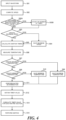
- step S01 when the waveform of the input signal (pulse signal) generated by a waveform shaping part 22 of the power generator 20 is inputted (step S01), the controller 30 causes the speed computation part 31 to compute the engine rotational speed with the period T of the input signal (the time difference from the previous input) (step S02), and determines whether the computed speed exceeds a set value (step S02A).
- step S02A When determining that the computed speed exceeds the set value (step S02A; YES), the controller 30 counts up the number of times the computed speed exceeds the set value (step S02B).
- the controller 30 determines whether to update the maximum speed by comparison between the presently obtained speed and the maximum speed previously obtained (step S03).
- the controller 30 causes the memory 34 to store the presently obtained speed as the maximum speed (step S04).
- the step S03 of the comparative determination when the waveform is inputted the first time, the presently obtained speed is stored as is in the memory 34 as the maximum speed.
- the controller 30 when determining not to update the maximum speed (step S03; NO) or after the maximum speed is saved in the memory 34, the controller 30 causes the ignition timing calculation part 32 to calculate the ignition timing with the presently obtained speed (step S05) .
- the controller 30 upon receiving the input signal described above, causes the temperature measurement part 33 to obtain a detection signal from the sensor 2 to measure the temperature (step S06). Then, the controller 30 determines whether to update the maximum temperature by comparison between the presently obtained temperature and the maximum temperature previously obtained (step S07). When determining to update the maximum temperature (step S07; YES), the controller 30 causes the memory 34 to store the presently obtained temperature as the maximum temperature (step S09) .
- step S07 when determining not to update the maximum temperature (step S07; NO), the controller 30 determines whether to update the minimum temperature by comparison between the presently obtained temperature and the minimum temperature previously obtained (step S08). When determining to update the minimum temperature (step S08; YES), the controller 30 causes the memory 34 to store the presently obtained temperature as the minimum temperature (step S10). In the step S07 and the step S08 of the comparative determination, when the waveform is inputted the first time, the presently obtained temperature is stored as is in the memory 34 as the maximum temperature and the minimum temperature.
- the controller 30 After determining to update the maximum temperature and the minimum temperature, the controller 30 causes the matrix determination part 36 to perform matrix determination, based on the presently obtained speed and temperature (step S11).
- the controller 30 determines which of the preset matrix sections (An, Bn) corresponds to the presently obtained speed and temperature; obtains the timer value from the timer 35 having counted the period T of the input signal (step S12); and cumulates the obtained timer value for each of the corresponding matrix sections (step S13). After that, the controller 30 outputs an output signal to the ignition circuit 10 at the ignition timing obtained in the step S05 to make the thyristor 16 of the ignition circuit 10 conductive, and performs ignition for each of the input signals (step S14).
- the controller 30 discriminates the continuity of the input signals to obtain the number of times of trying recoil and the number of times of starting the operating status data, and saves the data in the memory 34 as needed (not illustrated in the flowchart of Fig. 4 ).
- the controller 30 determines the starting when the engine continues to be rotated a set number of times at an engine rotational speed equal to or higher than a set value, and counts up the number of times of the starting, and determines the recoil when the input signals continue to be inputted after the controller 30 is powered on before the engine is started.
- controller 30 sums the cumulative time for each of the matrix sections stored as the matrix data to obtain the total operating time as the operating status data.
- the controller 30 can cause the memory 34 to save log data of the speed and the temperature obtained for each of the input signals by adding a step to the flowchart of Fig. 4 .
- the controller 30 causes the memory 34 to continuously save the log data every several seconds for several minutes, and after a set period of time has elapsed, overwrites the old data to save new log data.
- the controller 30 can cause the memory 34 to save significant log data such as the log data just before the engine stop with a limited memory capacity.
- this ignition coil unit 1 it is possible to precisely determine the time for maintenance or replacement and diagnose failure by an appropriate evaluation index, by referring to the matrix data and the operating status data stored in the memory 34 which is built in the ignition coil unit 1.
- the memory function of the ignition coil unit 1 essential to the engine is enriched, and therefore it is possible to solve the problems with precise maintenance and so forth at lower cost.
- the diagnostic system includes, for example, a display device configured to display the matrix data and the operating status data stored in the memory 34.
- the memory 34 has already stored user information such as user ID, and therefore it is possible to refer to or analyze the matrix data and the operating status data retrieved from the memory 34 in association with the user information.
- the dealer can provide the individual user with service corresponding to the characteristic of the user.
- the matrix data of the engine rotational speed and the temperature indicates that the engine is operated within a predetermined range of rotational speeds and a predetermined range of temperatures, it can be information to understand that the user ideally uses the engine, and, on the other hand, when the matrix data of the engine rotational speed and the temperature indicates that the engine is operated out of the predetermined range of rotational speeds and the predetermined range of temperatures, it can be information to understand that the user does not ideally use the engine.
- the maximum rotational speed, the number of times the rotational speed exceeds the set value, and the maximum temperature and the minimum temperature in use can be information for the dealer to determine whether the user ideally uses the engine.
- the number of times of rotation exceeds a value equal to or higher than the set value it is possible to analyze that the failure is caused by a high rotational speed.
- it is possible to analyze that the failure is caused by the temperature by inspecting from the maximum or minimum temperature in use whether the engine is used under a condition in conformity to the requirement of the service temperature of electronic parts in the ignition coil unit 1.
- the matrix data and the operating status data presented from the dealer to the user can be used as information to teach the user about the operation getting close to the ideal use.
- the starting capability of the working machine can be information for the dealer to know the state of the working machine, for example, the deterioration of the working machine.
- the starting capability of the working machine has a cause-and-effect relationship with the operating environment, and therefore the dealer can understand the effect of the operating environment on the starting capability of the working machine, by analyzing the correlation of the number of times of trying recoil or the number of times of starting with the matrix data or the maximum temperature and the minimum temperature.
- the ignition coil unit 1 As described above, by employing the ignition coil unit 1 according to the embodiment of the invention, it is possible to understand the operating characteristic (operating status) of the user, and the state and the operating environment of the working machine, by the matrix data and the operating status data (total operating time, the maximum temperature in use, the maximum rotation frequency, the number of times of trying recoil, and the number of times of starting). Therefore, the dealer can propose the next time for maintenance to the individual users, based on the operating characteristic of each of the users.
- the dealer can determine whether the user is a heavy user who frequently uses the working machine or a light user who infrequently uses the working machine, based on the operating status data such as the total operating time. Therefore, when introducing a new product or article to the user, the dealer can provide the product or article corresponding to the status of use of the user, and after that, provide maintenance corresponding to the status of use of the user.
- the ignition coil unit 1 allows understanding the status of use of the user, the cause of failure, and the state and the operating environment of the working machine, by the matrix data and the operating status data. Therefore, it is possible to provide precise evaluation for the maintenance of the engine and the working machine, and consequently to provide service to the individual users which corresponds to the operating characteristic of each of the users.
Landscapes
- Engineering & Computer Science (AREA)
- Chemical & Material Sciences (AREA)
- Combustion & Propulsion (AREA)
- Mechanical Engineering (AREA)
- General Engineering & Computer Science (AREA)
- Power Engineering (AREA)
- Theoretical Computer Science (AREA)
- Signal Processing (AREA)
- Physics & Mathematics (AREA)
- General Physics & Mathematics (AREA)
- Ignition Installations For Internal Combustion Engines (AREA)
- Combined Controls Of Internal Combustion Engines (AREA)
Description
- The present invention relates to an ignition coil unit.
- A unitized ignition coil (hereinafter referred to as "ignition coil unit") is employed in an engine widely used as a power source for a handheld working machine such as a sprayer, a spreader, and a mower. For example, the ignition coil unit including: a generator coil configured to generate an induced voltage in synchronization with the rotation of the engine; an ignition circuit including a primary coil and a secondary coil; and an ignition control circuit configured to supply an ignition voltage to the primary coil at a predetermined ignition timing based on the voltage induced by the generator coil, which are unitized, for example, by resin-molding, has been disclosed in
Japanese Unexamined Patent Application Publication No. 2008-75502 -
EP 1 277 939 A2 discloses an ignition time controlling system for light duty combustion engines. The system comprises the features of the preamble of claim 1 herein. -
DE 20 2018 105 999 U1 describes a system for analyzing an operation of a hand-held processing device having a processing tool and a drive system for driving the processing tool. The system comprises an optical recording device, which is designed to record a time sequence of images of a machining of a machining piece with the machining tool, a capturing device adapted to capture a time sequence of operating data values of the drive system during the recording of the time sequence of images, and at least one output device, which is designed to output in each case at least one of the recorded images with at least one operating data value of the drive system operating data value time-assigned thereto. - In addition, for example, a time totaling meter configured to calculate a cumulative operating time of an engine and a working machine using an ignition pulse has been proposed in
Japanese Unexamined Patent Application Publication No. H08-170989 - This time totaling meter can count, store, and display the cumulative time of the engine from the starting of operation, and a user can conduct maintenance and repair of the engine and the working machine based on data of the cumulative time.
- The ignition coil unit can obtain the data of the cumulative time for maintenance of the engine and the working machine by installing the above-described time totaling meter. However, it is not possible to specifically know the operating states of the engine and the working machine only by cumulating the operating time, and therefore not possible to conduct a precise evaluation for the maintenance.
- Moreover, the knowledge of the operating states of the individual engine and working machine when used allows understanding of the operating characteristics or habits of users. The operating characteristics of the users are different for each of the users, and there is demand to provide proper service to each of the users after understanding the operating characteristics of the individual users.
- The present invention is proposed to address the above-described problem. It is therefore an object of the present invention to provide an ignition coil unit capable of conducting precise maintenance of an engine and a working machine with a proper evaluation index, and providing proper service to each of the users after knowing the operating state of the individual engine or working machine and understanding the operating characteristic of the user.
- Said object is solved by an ignition coil unit according to claim 1.
- According to the present invention, it is possible to conduct precise maintenance of an engine and a working machine with an appropriate evaluation index, and provide proper service to each of the users after knowing the operating state of the individual engine or working machine and understanding the operating characteristic of the user.
-
-
Fig. 1 illustrates a constitutional example of an ignition coil unit according to an embodiment of the present invention; -
Fig. 2A illustrates the waveform of an induced voltage generated by a generator coil in a waveform shaping circuit of a power generator; -
Fig. 2B illustrates shaped waveforms; -
Fig. 2C illustrates a waveform period; -
Fig. 3 illustrates an example of matrix data stored in a memory; and -
Fig. 4 is a flowchart illustrating an example of the operation of a controller. - Hereinafter, an embodiment of the present invention will be described with reference to the drawings. The same reference numbers in the different drawings indicate the same functional sections, and therefore repeated description for each of the drawings is omitted.
- In
Fig. 1 , an ignition coil unit 1 includes anignition circuit 10, apower generator 20, acontroller 30 and asensor 2, which are unitized. - The
ignition circuit 10 includes aprimary coil 11, asecondary coil 12, acapacitor 13,diodes thyristor 16. Theprimary coil 11 is supplied with an ignition voltage of electricity stored in thecapacitor 13, and a spark plug 3 is connected to thesecondary coil 12. An induced voltage generated by thegenerator coil 21 of thepower generator 20 is rectified by thediode 14 and stored in thecapacitor 13. When thethyristor 16 is controlled to be conductive by thecontroller 30, thecapacitor 13 discharges to flow a current to theprimary coil 11. When the current is flowed to theprimary coil 11, a high voltage is induced in thesecondary coil 12 accordingly, and then a spark is generated by the spark plug 3 connected to thesecondary coil 12. - The
power generator 20 includes the above-describedgenerator coil 21, and also includes awaveform shaping circuit 22. Thepower generator 20 accumulates electricity in thecapacitor 13 with the induced voltage of thegenerator coil 21. Thewaveform shaping circuit 22 shapes the waveform of the induced voltage of thegenerator coil 21. Thewaveform shaping circuit 22 shapes the waveform of the induced voltage generated by thegenerator coil 21 as illustrated inFig. 2A into two waveforms as illustrated inFig. 2B . The waveform shaped by thewaveform shaping circuit 22 can be treated as a pulse signal having period T as illustrated inFig. 2C , which becomes an input signal to thecontroller 30. - The
controller 30 controls the ignition timing of theignition circuit 10, that is, the timing at which thethyristor 16 becomes conductive by the input signal from thewaveform shaping circuit 22 which is generated by the induced voltage of thegenerator coil 21. For this timing control, thecontroller 30 includes aspeed computation part 31 and an ignitiontiming calculation part 32. - The
speed computation part 31 computes an engine rotational speed or frequency as operating information, based on the input signal from thewaveform shaping circuit 22. The input signal can be treated as a pulse signal having the period T as described above, and therefore it is possible to obtain the engine rotational speed by calculating the reciprocal of the period T (1/T). - The ignition
timing calculation part 32 calculates and outputs the ignition timing according to the engine rotational speed obtained by thespeed computation part 31. The ignition timing is calculated for each rotation of the engine, and a signal to make thethyristor 16 conductive is outputted at a predetermined timing. - The
sensor 2 of the ignition coil unit 1 detects load information and inputs the load information to thecontroller 30. The load information is temperature information and provides knowledge of the load state of the engine with the ignition coil 1, or the working machine equipped with this engine during the operation. Thus, thesensor 2 is a temperature sensor used to detect the temperature information. Hereinafter, the temperature sensor is used as thesensor 2 and the temperature in the unit is detected as the load information will be described. - The
controller 30 includes atemperature measurement part 33 configured to measure the temperature from a detection signal of thesensor 2. Thecontroller 30 also includes amemory 34 configured to store the engine rotational speed as the operating information outputted from thespeed computation part 31 and the temperature in the unit as the load information outputted from thetemperature measurement part 33 in chronological order by using a time stamp function of thecontroller 30. Moreover, thecontroller 30 includes atimer 35 configured to allow thememory 34 to store working time information corresponding to the engine rotational speed as the operating information and the temperature in the unit as the load information described above. - The
controller 30 includes amatrix determination part 36 configured to allow thememory 34 to store the working time information corresponding to the engine rotational speed (hereinafter "speed") as the operating information and the temperature in the unit (hereinafter "temperature") as the load information, as matrix data composed of the operating information, the load information, and the time data. -
Fig. 3 illustrates a constitutional example of the matrix data produced by thematrix determination part 36. Here, two axes of the sections of the matrix constituting the matrix data indicate speed (r/min) and temperature (°C), respectively. - The
matrix determination part 36 determines which of 25 sections of the matrix (An, Bn) {(A1, B1), (A1, B2),..., (A1, B5), (A2, B1),..., (A2, B5),..., (A5, B5)} corresponds to the speed and the temperature of the engine during the operation. Thetimer 35 measures the working time of the corresponding section to obtain a cumulation of the working time of each of the sections. Then, thecontroller 30 causes thememory 34 to store the obtained cumulative time. - In addition, the
controller 30 also causes thememory 34 to store operating status data. This operating status data includes at least one of the total operating time of the working machine, the maximum value of the operating information such as the engine rotational speed, the maximum value of the load information such as the temperature in the unit, the number of times of trying recoil to start the engine, the number of times of starting (number of start) of the engine, and the number of times the engine rotational speed exceeds a set value. Thecontroller 30 updates the operating status data as needed, and causes thememory 34 to store the data. - The operation of the
controller 30 described above will be explained in detail with reference to the flowchart ofFig. 4 . First, when the waveform of the input signal (pulse signal) generated by awaveform shaping part 22 of thepower generator 20 is inputted (step S01), thecontroller 30 causes thespeed computation part 31 to compute the engine rotational speed with the period T of the input signal (the time difference from the previous input) (step S02), and determines whether the computed speed exceeds a set value (step S02A). When determining that the computed speed exceeds the set value (step S02A; YES), thecontroller 30 counts up the number of times the computed speed exceeds the set value (step S02B). - Then, the
controller 30 determines whether to update the maximum speed by comparison between the presently obtained speed and the maximum speed previously obtained (step S03). When determining to update the maximum speed (step S03; YES), thecontroller 30 causes thememory 34 to store the presently obtained speed as the maximum speed (step S04). In the step S03 of the comparative determination, when the waveform is inputted the first time, the presently obtained speed is stored as is in thememory 34 as the maximum speed. - On the other hand, when determining not to update the maximum speed (step S03; NO) or after the maximum speed is saved in the
memory 34, thecontroller 30 causes the ignition timingcalculation part 32 to calculate the ignition timing with the presently obtained speed (step S05) . - In addition, upon receiving the input signal described above, the
controller 30 causes thetemperature measurement part 33 to obtain a detection signal from thesensor 2 to measure the temperature (step S06). Then, thecontroller 30 determines whether to update the maximum temperature by comparison between the presently obtained temperature and the maximum temperature previously obtained (step S07). When determining to update the maximum temperature (step S07; YES), thecontroller 30 causes thememory 34 to store the presently obtained temperature as the maximum temperature (step S09) . - On the other hand, when determining not to update the maximum temperature (step S07; NO), the
controller 30 determines whether to update the minimum temperature by comparison between the presently obtained temperature and the minimum temperature previously obtained (step S08). When determining to update the minimum temperature (step S08; YES), thecontroller 30 causes thememory 34 to store the presently obtained temperature as the minimum temperature (step S10). In the step S07 and the step S08 of the comparative determination, when the waveform is inputted the first time, the presently obtained temperature is stored as is in thememory 34 as the maximum temperature and the minimum temperature. - After determining to update the maximum temperature and the minimum temperature, the
controller 30 causes thematrix determination part 36 to perform matrix determination, based on the presently obtained speed and temperature (step S11). - In the matrix determination, the
controller 30 determines which of the preset matrix sections (An, Bn) corresponds to the presently obtained speed and temperature; obtains the timer value from thetimer 35 having counted the period T of the input signal (step S12); and cumulates the obtained timer value for each of the corresponding matrix sections (step S13). After that, thecontroller 30 outputs an output signal to theignition circuit 10 at the ignition timing obtained in the step S05 to make thethyristor 16 of theignition circuit 10 conductive, and performs ignition for each of the input signals (step S14). - The
controller 30 discriminates the continuity of the input signals to obtain the number of times of trying recoil and the number of times of starting the operating status data, and saves the data in thememory 34 as needed (not illustrated in the flowchart ofFig. 4 ). Here, thecontroller 30 determines the starting when the engine continues to be rotated a set number of times at an engine rotational speed equal to or higher than a set value, and counts up the number of times of the starting, and determines the recoil when the input signals continue to be inputted after thecontroller 30 is powered on before the engine is started. - Moreover, the
controller 30 sums the cumulative time for each of the matrix sections stored as the matrix data to obtain the total operating time as the operating status data. - The
controller 30 can cause thememory 34 to save log data of the speed and the temperature obtained for each of the input signals by adding a step to the flowchart ofFig. 4 . In this case, for example, thecontroller 30 causes thememory 34 to continuously save the log data every several seconds for several minutes, and after a set period of time has elapsed, overwrites the old data to save new log data. By this means, thecontroller 30 can cause thememory 34 to save significant log data such as the log data just before the engine stop with a limited memory capacity. - According to this ignition coil unit 1, it is possible to precisely determine the time for maintenance or replacement and diagnose failure by an appropriate evaluation index, by referring to the matrix data and the operating status data stored in the
memory 34 which is built in the ignition coil unit 1. In addition, it is possible to understand the operation characteristic of the user of the individual engine or working machine, and the status of use of the working machine by analyzing the data stored in thememory 34 built in the ignition coil unit 1 of the individual engine, and therefore to provide service to each user with the personalized menu for the user. Moreover, the memory function of the ignition coil unit 1 essential to the engine is enriched, and therefore it is possible to solve the problems with precise maintenance and so forth at lower cost. - Hereinafter, an example of practical use of this ignition coil unit 1 will be specifically described. For example, at the time for maintenance, the user of the working machine brings the working machine to a dealer or store. Then, the ignition coil unit 1 is removed from the engine, and the
memory 34 of the ignition coil unit 1 is connected to a diagnostic system. The diagnostic system includes, for example, a display device configured to display the matrix data and the operating status data stored in thememory 34. - In this case, the
memory 34 has already stored user information such as user ID, and therefore it is possible to refer to or analyze the matrix data and the operating status data retrieved from thememory 34 in association with the user information. By employing this diagnostic system, the dealer can provide the individual user with service corresponding to the characteristic of the user. - Understanding the status of use from the matrix data can be used as a material for determining how the user is using the engine. When the matrix data of the engine rotational speed and the temperature indicates that the engine is operated within a predetermined range of rotational speeds and a predetermined range of temperatures, it can be information to understand that the user ideally uses the engine, and, on the other hand, when the matrix data of the engine rotational speed and the temperature indicates that the engine is operated out of the predetermined range of rotational speeds and the predetermined range of temperatures, it can be information to understand that the user does not ideally use the engine.
- In addition, in the case of understanding the status of use of the engine by the operating status data, the maximum rotational speed, the number of times the rotational speed exceeds the set value, and the maximum temperature and the minimum temperature in use can be information for the dealer to determine whether the user ideally uses the engine. In particular, in the case of analyzing the cause of a failure, when the number of times of rotation exceeds a value equal to or higher than the set value, it is possible to analyze that the failure is caused by a high rotational speed. In addition, it is possible to analyze that the failure is caused by the temperature, by inspecting from the maximum or minimum temperature in use whether the engine is used under a condition in conformity to the requirement of the service temperature of electronic parts in the ignition coil unit 1. Moreover, in particular, when the engine fails many times, the matrix data and the operating status data presented from the dealer to the user, can be used as information to teach the user about the operation getting close to the ideal use.
- In the case of understanding the status of use of the engine by another operating status data, it is possible to evaluate the starting capability of the working machine by the number of times of trying recoil and the number of times of starting. The starting capability of the working machine can be information for the dealer to know the state of the working machine, for example, the deterioration of the working machine. In addition, the starting capability of the working machine has a cause-and-effect relationship with the operating environment, and therefore the dealer can understand the effect of the operating environment on the starting capability of the working machine, by analyzing the correlation of the number of times of trying recoil or the number of times of starting with the matrix data or the maximum temperature and the minimum temperature.
- As described above, by employing the ignition coil unit 1 according to the embodiment of the invention, it is possible to understand the operating characteristic (operating status) of the user, and the state and the operating environment of the working machine, by the matrix data and the operating status data (total operating time, the maximum temperature in use, the maximum rotation frequency, the number of times of trying recoil, and the number of times of starting). Therefore, the dealer can propose the next time for maintenance to the individual users, based on the operating characteristic of each of the users.
- Moreover, the dealer can determine whether the user is a heavy user who frequently uses the working machine or a light user who infrequently uses the working machine, based on the operating status data such as the total operating time. Therefore, when introducing a new product or article to the user, the dealer can provide the product or article corresponding to the status of use of the user, and after that, provide maintenance corresponding to the status of use of the user.
- As described above, the ignition coil unit 1 according to the embodiment of the invention allows understanding the status of use of the user, the cause of failure, and the state and the operating environment of the working machine, by the matrix data and the operating status data. Therefore, it is possible to provide precise evaluation for the maintenance of the engine and the working machine, and consequently to provide service to the individual users which corresponds to the operating characteristic of each of the users.
- As described above, the embodiments of the present invention have been described in detail with reference to the drawings. However, the specific configuration is not limited to the embodiments, and the design can be changed within the scope of the attached claims. In addition, the above-described embodiments can be combined by utilizing each other's technology as long as there is no particular contradiction or problem in the purpose and configuration, but only within the scope of the attached claims.
Claims (2)
- An ignition coil unit (1) comprising:an ignition circuit (10) including a primary coil (11) and a secondary coil (12);a power generator (20) including a generator coil (21) ;a controller (30) configured to control an ignition timing of the ignition circuit (10) by an input signal generated by an induced voltage of the generator coil (21) and to compute an engine rotational speed based on said input signal; anda temperature sensor (2) configured to input a temperature in the ignition coil unit (1) to the controller (30),characterized in that the controller (30) includes a memory (34) with matrix data stored therein;wherein the matrix data is a cumulation of the working time information as a function of said engine rotational speed and said temperature in the ignition coil unit (1) which is obtained for each of the matrix sections;wherein two axes of the sections of a matrix constituting the matrix data indicate speed (r/min) and temperature (°C), respectively;wherein the controller (30) is configured to determine which of the sections of the matrix corresponds to the current engine rotational speed and the current temperature of the engine during an operation;wherein the controller (30) is configured to measure a working time of a corresponding section to obtain a cumulation of the working time of each of the sections;wherein the controller (30) is configured to cause the memory (34) to store an obtained cumulative time in the determined section;wherein the memory (34) is also configured to store user information;wherein the controller (30) is configured to update operating status data as needed and to store it into the memory (34);wherein the operating status data includes at least one of the total operating time of the working machine, the maximum value of operating information such as the engine rotational speed, the maximum value of load information such as the temperature in the ignition coil unit, the number of times of trying recoil to start the engine, the number of times of starting of the engine, and the number of times the engine rotational speed exceeds a set value; andwherein the ignition coil unit is comprising means to connect the memory to a diagnostic system in order to analyse the matrix data and the operating status data in association with the user information.
- The ignition coil unit (1) according to claim 1, wherein:the input signal is a pulse signal obtained by shaping a waveform of the induced voltage of the generator coil (21); andthe operating information is obtained by computing a pulse period of the pulse signal.
Applications Claiming Priority (1)
| Application Number | Priority Date | Filing Date | Title |
|---|---|---|---|
| JP2020174757A JP7490526B2 (en) | 2020-10-16 | 2020-10-16 | Ignition coil unit |
Publications (2)
| Publication Number | Publication Date |
|---|---|
| EP3985244A1 EP3985244A1 (en) | 2022-04-20 |
| EP3985244B1 true EP3985244B1 (en) | 2025-01-22 |
Family
ID=78649095
Family Applications (1)
| Application Number | Title | Priority Date | Filing Date |
|---|---|---|---|
| EP21202872.4A Active EP3985244B1 (en) | 2020-10-16 | 2021-10-15 | Ignition coil unit collecting operating data |
Country Status (4)
| Country | Link |
|---|---|
| US (1) | US11761415B2 (en) |
| EP (1) | EP3985244B1 (en) |
| JP (1) | JP7490526B2 (en) |
| CN (1) | CN114382628B (en) |
Family Cites Families (20)
| Publication number | Priority date | Publication date | Assignee | Title |
|---|---|---|---|---|
| JP3717545B2 (en) | 1994-10-18 | 2005-11-16 | 追浜工業株式会社 | Integrating hour meter for internal combustion engine |
| US20030015175A1 (en) * | 2001-07-18 | 2003-01-23 | Andersson Martin N. | Ignition timing control system for light duty combustion engines |
| EP2383462A1 (en) * | 2002-04-12 | 2011-11-02 | Iida Denki Kogyo Co., Ltd. | Method and device for controlling ignition timing of ignition device for internal combustion engine |
| JP4120520B2 (en) * | 2003-07-28 | 2008-07-16 | 株式会社デンソー | Control device for internal combustion engine |
| JP4254554B2 (en) | 2004-01-23 | 2009-04-15 | スズキ株式会社 | Engine management device for outboard motor |
| JP2008075502A (en) | 2006-09-20 | 2008-04-03 | Oppama Kogyo Kk | Non-contact ignition control device for internal combustion engine |
| JP4826802B2 (en) * | 2007-03-19 | 2011-11-30 | 国産電機株式会社 | Ignition device for internal combustion engine |
| JP5227742B2 (en) | 2008-10-28 | 2013-07-03 | ヤンマー株式会社 | Engine generator |
| JP2010151124A (en) * | 2008-11-20 | 2010-07-08 | Oppama Kogyo Kk | Work apparatus with internal combustion engine |
| US10685299B2 (en) | 2012-03-08 | 2020-06-16 | Husqvarna Ab | Engine speed data usage system and method |
| US9367062B2 (en) | 2012-12-31 | 2016-06-14 | Robert Bosch Gmbh | System and method for operational data retrieval from a power tool |
| JP6127591B2 (en) | 2013-03-06 | 2017-05-17 | 追浜工業株式会社 | Ignition control device for internal combustion engine |
| JP6609178B2 (en) * | 2015-12-24 | 2019-11-20 | 株式会社やまびこ | 2-cycle internal combustion engine |
| JP6696334B2 (en) * | 2016-07-11 | 2020-05-20 | 株式会社デンソー | Ignition device |
| EP3291181B1 (en) | 2016-09-05 | 2021-11-03 | Andreas Stihl AG & Co. KG | Device and system for detecting operating data of a tool |
| JP7135441B2 (en) * | 2018-05-25 | 2022-09-13 | 株式会社デンソー | Ignition device for internal combustion engine |
| JP6995988B2 (en) * | 2018-05-30 | 2022-02-04 | 本田技研工業株式会社 | Ignition coil controller |
| DE202018105999U1 (en) | 2018-10-19 | 2018-10-30 | Andreas Stihl Ag & Co. Kg | System for analyzing an operation of a hand-held processing device |
| JP6698906B1 (en) * | 2019-04-02 | 2020-05-27 | 三菱電機株式会社 | Internal combustion engine discharge state detection device |
| US11274645B2 (en) * | 2019-10-15 | 2022-03-15 | Semiconductor Components Industries, Llc | Circuit and method for a kickback-limited soft shutdown of a coil |
-
2020
- 2020-10-16 JP JP2020174757A patent/JP7490526B2/en active Active
-
2021
- 2021-10-14 US US17/501,179 patent/US11761415B2/en active Active
- 2021-10-15 EP EP21202872.4A patent/EP3985244B1/en active Active
- 2021-10-15 CN CN202111202176.1A patent/CN114382628B/en active Active
Also Published As
| Publication number | Publication date |
|---|---|
| CN114382628B (en) | 2025-08-01 |
| EP3985244A1 (en) | 2022-04-20 |
| CN114382628A (en) | 2022-04-22 |
| JP2022065932A (en) | 2022-04-28 |
| JP7490526B2 (en) | 2024-05-27 |
| US11761415B2 (en) | 2023-09-19 |
| US20230003184A1 (en) | 2023-01-05 |
Similar Documents
| Publication | Publication Date | Title |
|---|---|---|
| EP1558940B1 (en) | Device and method of monitoring the starting capability of a vehicles starter battery | |
| JP6760119B2 (en) | Battery temperature estimation device, battery temperature estimation method and computer program | |
| US4719427A (en) | Vehicle battery diagnostic device | |
| US7089127B2 (en) | Integrated battery service system | |
| CN100451670C (en) | Battery capacity detection apparatus and detection method | |
| JP5391749B2 (en) | Battery diagnostic device | |
| US3955135A (en) | Vehicle rpm and dwell measurement system | |
| EP3985244B1 (en) | Ignition coil unit collecting operating data | |
| US20050096868A1 (en) | Reciprocating engine cylinder contribution tester and method | |
| WO2004081896A1 (en) | In-use unambiguously determining the near-end-of-life state of a combustion engine battery | |
| EP2875235A1 (en) | Diagnostics for a starter motor | |
| US6646561B1 (en) | Method and device for in-use detecting low cranking strength of a combustion engine battery during engine starting | |
| US3961239A (en) | Signal conditioning circuit for vehicle diagnostic system | |
| JPH0829465A (en) | Capacitor capacitance change detection circuit and power supply life detection circuit | |
| JP7514163B2 (en) | Engine diagnostic equipment for construction machinery | |
| Hasan et al. | Micro-Controller Based on-board diagnostic (OBD) system for non-OBD vehicles | |
| US3979598A (en) | Dual range adjustable delay circuit | |
| EP0591871A1 (en) | A method and apparatus for the diagnostic testing of electrical equipment of a vehicle | |
| JP4670256B2 (en) | Battery status detection method | |
| CN115552252B (en) | Method for estimating the time during which an endothermic motor operates at a predetermined speed by measuring with an inductive sensor and apparatus for implementing the method | |
| WO2025070091A1 (en) | Engine starting performance diagnostic device for construction machine | |
| JP2025039225A (en) | Engine diagnostic equipment | |
| CN110646735A (en) | Method for detecting low starting intensity of internal combustion engine battery during engine starting | |
| IE43405B1 (en) | Adjustable delay circuit, for particulary a vehicle diagnostic system |
Legal Events
| Date | Code | Title | Description |
|---|---|---|---|
| PUAI | Public reference made under article 153(3) epc to a published international application that has entered the european phase |
Free format text: ORIGINAL CODE: 0009012 |
|
| STAA | Information on the status of an ep patent application or granted ep patent |
Free format text: STATUS: THE APPLICATION HAS BEEN PUBLISHED |
|
| AK | Designated contracting states |
Kind code of ref document: A1 Designated state(s): AL AT BE BG CH CY CZ DE DK EE ES FI FR GB GR HR HU IE IS IT LI LT LU LV MC MK MT NL NO PL PT RO RS SE SI SK SM TR |
|
| STAA | Information on the status of an ep patent application or granted ep patent |
Free format text: STATUS: REQUEST FOR EXAMINATION WAS MADE |
|
| 17P | Request for examination filed |
Effective date: 20221020 |
|
| RBV | Designated contracting states (corrected) |
Designated state(s): AL AT BE BG CH CY CZ DE DK EE ES FI FR GB GR HR HU IE IS IT LI LT LU LV MC MK MT NL NO PL PT RO RS SE SI SK SM TR |
|
| STAA | Information on the status of an ep patent application or granted ep patent |
Free format text: STATUS: EXAMINATION IS IN PROGRESS |
|
| 17Q | First examination report despatched |
Effective date: 20240111 |
|
| GRAP | Despatch of communication of intention to grant a patent |
Free format text: ORIGINAL CODE: EPIDOSNIGR1 |
|
| STAA | Information on the status of an ep patent application or granted ep patent |
Free format text: STATUS: GRANT OF PATENT IS INTENDED |
|
| INTG | Intention to grant announced |
Effective date: 20240819 |
|
| GRAS | Grant fee paid |
Free format text: ORIGINAL CODE: EPIDOSNIGR3 |
|
| GRAA | (expected) grant |
Free format text: ORIGINAL CODE: 0009210 |
|
| STAA | Information on the status of an ep patent application or granted ep patent |
Free format text: STATUS: THE PATENT HAS BEEN GRANTED |
|
| AK | Designated contracting states |
Kind code of ref document: B1 Designated state(s): AL AT BE BG CH CY CZ DE DK EE ES FI FR GB GR HR HU IE IS IT LI LT LU LV MC MK MT NL NO PL PT RO RS SE SI SK SM TR |
|
| REG | Reference to a national code |
Ref country code: GB Ref legal event code: FG4D |
|
| REG | Reference to a national code |
Ref country code: CH Ref legal event code: EP |
|
| REG | Reference to a national code |
Ref country code: DE Ref legal event code: R081 Ref document number: 602021025099 Country of ref document: DE Owner name: YAMABIKO CORPORATION, OHME-SHI, JP Free format text: FORMER OWNERS: OPPAMA INDUSTRY CO., LTD, YOKOSUKA-SHI, KANAGAWA-KEN, JP; YAMABIKO CORPORATION, OME-SHI, TOKYO, JP Ref country code: DE Ref legal event code: R081 Ref document number: 602021025099 Country of ref document: DE Owner name: OPPAMA INDUSTRY CO., LTD, YOKOSUKA-SHI, JP Free format text: FORMER OWNERS: OPPAMA INDUSTRY CO., LTD, YOKOSUKA-SHI, KANAGAWA-KEN, JP; YAMABIKO CORPORATION, OME-SHI, TOKYO, JP |
|
| REG | Reference to a national code |
Ref country code: IE Ref legal event code: FG4D |
|
| REG | Reference to a national code |
Ref country code: DE Ref legal event code: R096 Ref document number: 602021025099 Country of ref document: DE |
|
| REG | Reference to a national code |
Ref country code: SE Ref legal event code: TRGR |
|
| REG | Reference to a national code |
Ref country code: NL Ref legal event code: MP Effective date: 20250122 |
|
| PG25 | Lapsed in a contracting state [announced via postgrant information from national office to epo] |
Ref country code: NL Free format text: LAPSE BECAUSE OF FAILURE TO SUBMIT A TRANSLATION OF THE DESCRIPTION OR TO PAY THE FEE WITHIN THE PRESCRIBED TIME-LIMIT Effective date: 20250122 |
|
| PG25 | Lapsed in a contracting state [announced via postgrant information from national office to epo] |
Ref country code: RS Free format text: LAPSE BECAUSE OF FAILURE TO SUBMIT A TRANSLATION OF THE DESCRIPTION OR TO PAY THE FEE WITHIN THE PRESCRIBED TIME-LIMIT Effective date: 20250422 |
|
| PG25 | Lapsed in a contracting state [announced via postgrant information from national office to epo] |
Ref country code: FI Free format text: LAPSE BECAUSE OF FAILURE TO SUBMIT A TRANSLATION OF THE DESCRIPTION OR TO PAY THE FEE WITHIN THE PRESCRIBED TIME-LIMIT Effective date: 20250122 |
|
| PG25 | Lapsed in a contracting state [announced via postgrant information from national office to epo] |
Ref country code: PL Free format text: LAPSE BECAUSE OF FAILURE TO SUBMIT A TRANSLATION OF THE DESCRIPTION OR TO PAY THE FEE WITHIN THE PRESCRIBED TIME-LIMIT Effective date: 20250122 |
|
| PG25 | Lapsed in a contracting state [announced via postgrant information from national office to epo] |
Ref country code: ES Free format text: LAPSE BECAUSE OF FAILURE TO SUBMIT A TRANSLATION OF THE DESCRIPTION OR TO PAY THE FEE WITHIN THE PRESCRIBED TIME-LIMIT Effective date: 20250122 |
|
| REG | Reference to a national code |
Ref country code: LT Ref legal event code: MG9D |
|
| PG25 | Lapsed in a contracting state [announced via postgrant information from national office to epo] |
Ref country code: NO Free format text: LAPSE BECAUSE OF FAILURE TO SUBMIT A TRANSLATION OF THE DESCRIPTION OR TO PAY THE FEE WITHIN THE PRESCRIBED TIME-LIMIT Effective date: 20250422 Ref country code: IS Free format text: LAPSE BECAUSE OF FAILURE TO SUBMIT A TRANSLATION OF THE DESCRIPTION OR TO PAY THE FEE WITHIN THE PRESCRIBED TIME-LIMIT Effective date: 20250522 |
|
| REG | Reference to a national code |
Ref country code: AT Ref legal event code: MK05 Ref document number: 1761638 Country of ref document: AT Kind code of ref document: T Effective date: 20250122 |
|
| PG25 | Lapsed in a contracting state [announced via postgrant information from national office to epo] |
Ref country code: HR Free format text: LAPSE BECAUSE OF FAILURE TO SUBMIT A TRANSLATION OF THE DESCRIPTION OR TO PAY THE FEE WITHIN THE PRESCRIBED TIME-LIMIT Effective date: 20250122 |
|
| PG25 | Lapsed in a contracting state [announced via postgrant information from national office to epo] |
Ref country code: PT Free format text: LAPSE BECAUSE OF FAILURE TO SUBMIT A TRANSLATION OF THE DESCRIPTION OR TO PAY THE FEE WITHIN THE PRESCRIBED TIME-LIMIT Effective date: 20250522 Ref country code: LV Free format text: LAPSE BECAUSE OF FAILURE TO SUBMIT A TRANSLATION OF THE DESCRIPTION OR TO PAY THE FEE WITHIN THE PRESCRIBED TIME-LIMIT Effective date: 20250122 |
|
| PG25 | Lapsed in a contracting state [announced via postgrant information from national office to epo] |
Ref country code: BG Free format text: LAPSE BECAUSE OF FAILURE TO SUBMIT A TRANSLATION OF THE DESCRIPTION OR TO PAY THE FEE WITHIN THE PRESCRIBED TIME-LIMIT Effective date: 20250122 Ref country code: GR Free format text: LAPSE BECAUSE OF FAILURE TO SUBMIT A TRANSLATION OF THE DESCRIPTION OR TO PAY THE FEE WITHIN THE PRESCRIBED TIME-LIMIT Effective date: 20250423 |
|
| PG25 | Lapsed in a contracting state [announced via postgrant information from national office to epo] |
Ref country code: AT Free format text: LAPSE BECAUSE OF FAILURE TO SUBMIT A TRANSLATION OF THE DESCRIPTION OR TO PAY THE FEE WITHIN THE PRESCRIBED TIME-LIMIT Effective date: 20250122 |
|
| PG25 | Lapsed in a contracting state [announced via postgrant information from national office to epo] |
Ref country code: SM Free format text: LAPSE BECAUSE OF FAILURE TO SUBMIT A TRANSLATION OF THE DESCRIPTION OR TO PAY THE FEE WITHIN THE PRESCRIBED TIME-LIMIT Effective date: 20250122 |
|
| PG25 | Lapsed in a contracting state [announced via postgrant information from national office to epo] |
Ref country code: DK Free format text: LAPSE BECAUSE OF FAILURE TO SUBMIT A TRANSLATION OF THE DESCRIPTION OR TO PAY THE FEE WITHIN THE PRESCRIBED TIME-LIMIT Effective date: 20250122 |
|
| PG25 | Lapsed in a contracting state [announced via postgrant information from national office to epo] |
Ref country code: IT Free format text: LAPSE BECAUSE OF FAILURE TO SUBMIT A TRANSLATION OF THE DESCRIPTION OR TO PAY THE FEE WITHIN THE PRESCRIBED TIME-LIMIT Effective date: 20250122 |
|
| PG25 | Lapsed in a contracting state [announced via postgrant information from national office to epo] |
Ref country code: CZ Free format text: LAPSE BECAUSE OF FAILURE TO SUBMIT A TRANSLATION OF THE DESCRIPTION OR TO PAY THE FEE WITHIN THE PRESCRIBED TIME-LIMIT Effective date: 20250122 Ref country code: EE Free format text: LAPSE BECAUSE OF FAILURE TO SUBMIT A TRANSLATION OF THE DESCRIPTION OR TO PAY THE FEE WITHIN THE PRESCRIBED TIME-LIMIT Effective date: 20250122 |
|
| REG | Reference to a national code |
Ref country code: DE Ref legal event code: R097 Ref document number: 602021025099 Country of ref document: DE |
|
| PG25 | Lapsed in a contracting state [announced via postgrant information from national office to epo] |
Ref country code: RO Free format text: LAPSE BECAUSE OF FAILURE TO SUBMIT A TRANSLATION OF THE DESCRIPTION OR TO PAY THE FEE WITHIN THE PRESCRIBED TIME-LIMIT Effective date: 20250122 |
|
| PG25 | Lapsed in a contracting state [announced via postgrant information from national office to epo] |
Ref country code: SK Free format text: LAPSE BECAUSE OF FAILURE TO SUBMIT A TRANSLATION OF THE DESCRIPTION OR TO PAY THE FEE WITHIN THE PRESCRIBED TIME-LIMIT Effective date: 20250122 |
|
| PLBE | No opposition filed within time limit |
Free format text: ORIGINAL CODE: 0009261 |
|
| STAA | Information on the status of an ep patent application or granted ep patent |
Free format text: STATUS: NO OPPOSITION FILED WITHIN TIME LIMIT |
|
| 26N | No opposition filed |
Effective date: 20251023 |
|
| PGFP | Annual fee paid to national office [announced via postgrant information from national office to epo] |
Ref country code: DE Payment date: 20251028 Year of fee payment: 5 |
|
| PGFP | Annual fee paid to national office [announced via postgrant information from national office to epo] |
Ref country code: GB Payment date: 20251024 Year of fee payment: 5 |
|
| PGFP | Annual fee paid to national office [announced via postgrant information from national office to epo] |
Ref country code: FR Payment date: 20251024 Year of fee payment: 5 |
|
| PGFP | Annual fee paid to national office [announced via postgrant information from national office to epo] |
Ref country code: SE Payment date: 20251024 Year of fee payment: 5 |