EP3985166B1 - Appareil de defroissage portatif comportant un accessoire amovible - Google Patents
Appareil de defroissage portatif comportant un accessoire amovible Download PDFInfo
- Publication number
- EP3985166B1 EP3985166B1 EP21201314.8A EP21201314A EP3985166B1 EP 3985166 B1 EP3985166 B1 EP 3985166B1 EP 21201314 A EP21201314 A EP 21201314A EP 3985166 B1 EP3985166 B1 EP 3985166B1
- Authority
- EP
- European Patent Office
- Prior art keywords
- accessory
- treatment
- removal device
- head
- crease removal
- Prior art date
- Legal status (The legal status is an assumption and is not a legal conclusion. Google has not performed a legal analysis and makes no representation as to the accuracy of the status listed.)
- Active
Links
Images





Classifications
-
- D—TEXTILES; PAPER
- D06—TREATMENT OF TEXTILES OR THE LIKE; LAUNDERING; FLEXIBLE MATERIALS NOT OTHERWISE PROVIDED FOR
- D06F—LAUNDERING, DRYING, IRONING, PRESSING OR FOLDING TEXTILE ARTICLES
- D06F75/00—Hand irons
- D06F75/08—Hand irons internally heated by electricity
- D06F75/10—Hand irons internally heated by electricity with means for supplying steam to the article being ironed
- D06F75/20—Arrangements for discharging the steam to the article being ironed
-
- D—TEXTILES; PAPER
- D06—TREATMENT OF TEXTILES OR THE LIKE; LAUNDERING; FLEXIBLE MATERIALS NOT OTHERWISE PROVIDED FOR
- D06F—LAUNDERING, DRYING, IRONING, PRESSING OR FOLDING TEXTILE ARTICLES
- D06F87/00—Apparatus for moistening or otherwise conditioning the article to be ironed or pressed
-
- D—TEXTILES; PAPER
- D06—TREATMENT OF TEXTILES OR THE LIKE; LAUNDERING; FLEXIBLE MATERIALS NOT OTHERWISE PROVIDED FOR
- D06F—LAUNDERING, DRYING, IRONING, PRESSING OR FOLDING TEXTILE ARTICLES
- D06F73/00—Apparatus for smoothing or removing creases from garments or other textile articles by formers, cores, stretchers, or internal frames, with the application of heat or steam
-
- D—TEXTILES; PAPER
- D06—TREATMENT OF TEXTILES OR THE LIKE; LAUNDERING; FLEXIBLE MATERIALS NOT OTHERWISE PROVIDED FOR
- D06F—LAUNDERING, DRYING, IRONING, PRESSING OR FOLDING TEXTILE ARTICLES
- D06F75/00—Hand irons
- D06F75/08—Hand irons internally heated by electricity
- D06F75/10—Hand irons internally heated by electricity with means for supplying steam to the article being ironed
- D06F75/14—Hand irons internally heated by electricity with means for supplying steam to the article being ironed the steam being produced from water in a reservoir carried by the iron
- D06F75/18—Hand irons internally heated by electricity with means for supplying steam to the article being ironed the steam being produced from water in a reservoir carried by the iron the water being fed slowly, e.g. drop by drop, from the reservoir to a steam generator
-
- D—TEXTILES; PAPER
- D06—TREATMENT OF TEXTILES OR THE LIKE; LAUNDERING; FLEXIBLE MATERIALS NOT OTHERWISE PROVIDED FOR
- D06F—LAUNDERING, DRYING, IRONING, PRESSING OR FOLDING TEXTILE ARTICLES
- D06F75/00—Hand irons
- D06F75/08—Hand irons internally heated by electricity
- D06F75/24—Arrangements of the heating means within the iron; Arrangements for distributing, conducting or storing the heat
-
- D—TEXTILES; PAPER
- D06—TREATMENT OF TEXTILES OR THE LIKE; LAUNDERING; FLEXIBLE MATERIALS NOT OTHERWISE PROVIDED FOR
- D06F—LAUNDERING, DRYING, IRONING, PRESSING OR FOLDING TEXTILE ARTICLES
- D06F75/00—Hand irons
- D06F75/34—Handles; Handle mountings
-
- D—TEXTILES; PAPER
- D06—TREATMENT OF TEXTILES OR THE LIKE; LAUNDERING; FLEXIBLE MATERIALS NOT OTHERWISE PROVIDED FOR
- D06F—LAUNDERING, DRYING, IRONING, PRESSING OR FOLDING TEXTILE ARTICLES
- D06F75/00—Hand irons
- D06F75/30—Hand irons of special external shape or form
-
- D—TEXTILES; PAPER
- D06—TREATMENT OF TEXTILES OR THE LIKE; LAUNDERING; FLEXIBLE MATERIALS NOT OTHERWISE PROVIDED FOR
- D06F—LAUNDERING, DRYING, IRONING, PRESSING OR FOLDING TEXTILE ARTICLES
- D06F75/00—Hand irons
- D06F75/38—Sole plates
Definitions
- the present invention relates to the field of portable steaming devices, comprising a handle and a steam emission head connected to the handle, in which the steam emission head comprises a treatment face, intended to come vertically facing each other. of a garment for steaming, which is provided with at least one steam outlet port and a hot surface.
- the invention relates more particularly to a steaming device comprising an accessory intended to be removably mounted on the head.
- a portable steaming device comprising a handle and an emission head comprising a treatment face intended to come vertically opposite a garment to be steamed, the treatment face comprising steam outlet orifices and a hot surface intended to come into contact with the clothing.
- the device also includes a removable accessory that can be mounted on the treatment face to clean or de-gloss a garment.
- the accessory covers the hot surface of the treatment face so that the latter no longer comes into contact with the clothing, which reduces the heat transfer to the clothing and therefore the effectiveness of the wrinkle removal.
- the accessory includes a cushion intended to remove threads or fibers stuck to fabrics which is placed on only one side of the steam outlet holes so that the user must pay attention to the orientation of the device to properly treat the garment.
- the present invention aims to remedy this drawback by proposing a portable steaming device provided with one or more removable accessories allowing the device to offer several maintenance functions with improved performance and ergonomics of use.
- the subject of the invention is a steaming device comprising a body comprising a handle and a steam emission head connected to the handle, the steam emission head comprising a treatment face intended to come vertically into view of a garment to be steamed, the treatment face comprising at least one steam outlet port and a hot surface intended to come into contact with the garment, the device further comprising at least one accessory intended to be mounted in a removable manner on the steam emission head, characterized in that the hot surface is arranged at the end of a protuberance which projects from the body, at the level of the treatment face, the body comprising a peripheral surface which extends to the foot of the protuberance and in that the accessory comprises a through opening which engages around said protuberance when the accessory is mounted on the steam emission head, the accessory being positioned in front of the peripheral surface and having at least one treatment surface, extending at the periphery of the through opening, intended to come into contact with the garment.
- the device may also have one or more of the following characteristics, taken alone or in combination.
- the device comprises a fixing device making it possible to hold the accessory on the head.
- the fixing device comprises magnetic means ensuring the maintenance of the accessory on the treatment face.
- Such a characteristic has the advantage of ensuring good support for the accessory while offering very good ergonomics of use.
- the body comprises at least one magnet disposed behind the peripheral surface.
- the accessory rests on the peripheral surface when it is mounted on the steam emission head.
- Such a characteristic makes it possible to have good stability of the accessory on the head and to allow good heat transfer by conduction between the accessory and the steam emission head.
- the hot surface is in thermal contact with a heating body provided in the head.
- Such a characteristic allows heating of the hot surface by thermal conduction with the heating body.
- the heating body contains a vaporization chamber.
- Such a characteristic makes it possible to use the same heating body to heat the hot surface and to produce steam.
- the hot surface is metallic
- the peripheral surface extends parallel to the hot surface.
- the treatment surface extends substantially in the plane of the hot surface when the accessory is mounted on the head, so that the treatment surface of the accessory comes in the extension of the hot surface.
- the treatment surface of the accessory and the hot surface come simultaneously into contact with the garment to be treated when the device is applied against a garment.
- the accessory is reversible and comprises a first treatment surface and a second treatment surface arranged on two opposite faces of the accessory.
- reversible accessory we mean that it can be mounted in one direction or the other so as to reveal one or the other of the treatment surfaces.
- the first treatment surface and the second treatment surface have different surface conditions and/or materials.
- the treatment surface could consist of a metal plate, a rubber surface or a textile such as velvet, microfibers, etc.
- FIG. 1 represents a steaming device comprising a body having a portable plastic housing comprising a base 1 surmounted by a handle 2 and a head 3 for emitting steam, the base 1 comprising a flat lower face on which the steaming device can come to rest stably in a substantially vertical position.
- the base 1 of the steaming device includes an electrical power cord 10 allowing its connection to a domestic electrical network, and the steam emission head 3 has a rear face provided with a button 12 (visible on the figure 4 ) to turn on the steaming device.
- the base 1 contains an electric pump 4, visible on the Figure 4 , the operation of which is controlled by means of a trigger 5 arranged at the top of the handle 2, the trigger 5 actuating, in a manner known per se, a switch connected to an electronic control card of the pump 4, not shown on the figures.
- the pump 4 is supplied with liquid by a reservoir 11 provided in the base 1, this reservoir 11 being advantageously removable from the steaming device to facilitate its filling.
- the steam emission head 3 has a slender shape extending transversely to the longitudinal direction of the handle 2 and has a longitudinal end provided with a treatment face 30 intended to come vertically opposite a garment to be steamed.
- the treatment face 30 includes a protuberance 34 which projects from the body and which comprises an end supporting a hot surface 31, preferably metallic and of oblong shape.
- the protuberance 34 also comprises a series of steam outlet orifices 33 arranged in the bottom of a groove provided near the periphery of the protuberance 34.
- the protuberance 34 advantageously occupies a central position on the treatment face 30 and has a slightly frustoconical shape.
- the treatment face 30 presents, at the foot of the protrusion 34, a peripheral surface 32 which extends parallel to the hot surface 31 and forms a shoulder extending to the edge of the body of the head 3.
- the peripheral surface 32 is made by a metal part which is attached to the end of the head 3 and which is in thermal contact with a heating body 6, visible on the figures 4 And 5 , located inside the head 3.
- the heating body 6 has a general rectangular parallelepiped shape and comprises, in a manner known per se, a foundry, for example made of aluminum, and a resistive heating element 60, such as an electrical resistance, bent in a U and integrated into the foundry .
- the heating body 6 comprises a front face coming into thermal contact with the hot surface 31, the front end of the heating body 6 extending inside the protuberance 34. In this way, the hot surface 31 is heated by conduction thermal through the protuberance 34.
- the heating body 6 also includes a cover 61 which rests, in a sealed manner, on the foundry, and an instantaneous vaporization chamber 63 delimited by the foundry and the cover 61.
- the foundry more particularly comprises a peripheral wall on which the cover 61 rests. and which laterally delimits the instantaneous vaporization chamber 63.
- the supply of the resistive heating element 60 is regulated by means of a thermostat 9 (visible on the Figure 4 ) around a set temperature, measured at the center of the instantaneous vaporization chamber 63, for example between 110°C and 150°C.
- the cover 61 has two water injection orifices 68A opening into the instantaneous vaporization chamber 63 near the front end of the latter, the two water injection orifices 68A being connected to the pump 4 by the via a fluid delivery conduit (not shown in the figures).
- the instantaneous vaporization chamber 63 has a bottom wall forming a vaporization surface onto which the liquid injected via the two orifices water injection 68A is vaporized and has a passage 65 for the steam outlet provided on the peripheral wall, opposite the treatment face 30.
- the steaming device further comprises several deflection walls 69 extending in the instantaneous vaporization chamber 63 between the zone where water is injected onto the bottom wall and the passage 65 for the steam outlet. These deflection walls 69 form baffles configured to deflect the steam flow generated in the instantaneous vaporization chamber 63 and retain any water droplets that may be transported by the steam flow.
- the heating body 6 also includes a steam distribution circuit 66 in which the flow of steam coming from the instantaneous vaporization chamber 63 is intended to flow. According to the embodiment shown in the figures, the steam distribution circuit 66 is arranged around the instantaneous vaporization chamber 63.
- the steam distribution circuit 66 is fluidly connected on the one hand to the instantaneous vaporization chamber 63 via the passage 65 for the steam outlet, and on the other hand to the steam outlet orifices 33 via conduits 36 provided in the front face of the heating body 6.
- the steam distribution circuit 66 is thus configured to supply steam to the steam outlet orifices 33.
- the steam leaving the instantaneous vaporization chamber 63 via the passage 65 can be flow into the steam distribution circuit 66, on either side of the instantaneous vaporization chamber 63 to then be diffused through the conduits, the latter opening into a distribution chamber 35 provided upstream of the steam outlet orifices 33 visible on the figure 4 .
- the device comprises one or more accessories 7 intended to be mounted removably against the peripheral surface 32 of the head 3, each accessory 7 having a through opening 70 adapted to allow the passage of the protuberance 34 when the accessory 7 rests against the peripheral surface 32.
- the accessory 7 advantageously has an oblong shape whose external contour matches the shape of the external contour of the body of the head 3, the opening through 70 being arranged in a central position and having a shape matching the shape of the external contour of the protuberance 34 so that the insertion of the protuberance 34 in the through opening 70 ensures the centering of the accessory 7 on the head 3.
- the accessory 7 comprises a central body 71 made of plastic material comprising four metal inserts 72, distributed on either side of the through opening 70, and comprises a first flange 73 and a second flange 74 which are clipped onto two opposite faces of the central body 71 of the accessory 7, masking the metal inserts 72.
- the first flange 73 is covered with a first coating which defines a first treatment surface 75 and the second flange 74 is covered with a second coating, preferably different from the first coating, which defines a second treatment surface 76.
- the first treatment surface 75 is a metal plate which is affixed to the external face of the first flange 73.
- the metal plate is advantageously fixed by tabs 75A which are folded behind the first flange 73.
- the second treatment surface 76 is a textile, such as a velvet or a microfiber, which is affixed to the external face of the second flange 74.
- the textile is fixed using two retaining rings 76A, 76B which are respectively attached to the level of the peripheral edge and the through opening 70 of the second flange 74.
- the thickness of the accessory 7 corresponding substantially to the height of the protuberance 34 so that one of the treatment surfaces 75, 76 comes in the extension of the hot surface 31 when the other treatment surface 76 , 75 of the accessory 7 rests against the peripheral surface 32 of the head 3.
- the head 3 comprises four magnets 37 arranged behind the peripheral surface 32, and illustrated in dotted lines on the figure 2 , the magnets 37 being arranged so as to come opposite the metal inserts 72 carried by the accessory 7 when the latter is placed on the head 3.
- the device thus produced has the advantage of having an accessory 7 which is very ergonomic to put in place and remove the head 3 from the device.
- the user can place the accessory 7 on the head 3 simply by aligning the protuberance 34 with the through opening 70 of the accessory 7, and by engaging the accessory 7 on the head 3 so as to come and apply one of the treatment surfaces 75, 76 against the peripheral surface 32.
- the magnets 37 of the head 3 exert a magnetic attraction on the metal inserts 72 so that the accessory 7 is held in position on the head 3.
- the user can then use the device by activating the trigger 5 of the device, to cause the pump 4 to start and water to be sent into the vaporization chamber 63, causing the steam to escape through the steam outlet ports 33.
- the accessory 7 then has a treatment surface 75, 76 which is arranged all around the hot surface 31 and steam outlet orifices 33 so that the treatment surface 75, 76 provides the same efficiency treatment regardless of the direction of movement of the head 3 parallel to the garment.
- the user has the possibility of choosing, among the two treatment surfaces 75, 76 of the accessory, the one he will use to treat his garment.
- he can choose to place the accessory 7 on the head 3 such that it is the first treatment surface 75 or the second treatment surface 76 which finds itself exposed around the hot surface 31.
- the accessory 7 is arranged in such a way that the first treatment surface 75 is applied against the peripheral surface 32, then the second treatment surface 76 will find itself being the active surface which will come into contact with the garment . Conversely, when the user arranges the accessory 7 such that the second treatment surface 76 is applied against the peripheral surface 32, then the first treatment surface 75 will find itself being the active surface which will come in contact with clothing.
- Such a device therefore has the advantage, with a limited number of accessories 7, to offer a greater diversity of treatment surfaces.
- the device benefits from the entire surface of the plate metallic surface of the accessory 7, in addition to the hot surface 31, to heat the garment, the metallic surface of the accessory 7 then being heated by radiation and by thermal conduction with the protuberance 34 and the peripheral surface 32.
- the device can be used while benefiting from the properties of this surface to act on the garment.
- this surface is made up of velvet, the latter will exert traction on the garment, when the steaming head moves sideways along the garment, which will help to improve the steaming performance.
- this surface is made of microfiber, the latter will have the advantage of being very effective in removing dust or dirt which may be attached to clothing.
- the device may also include several accessories with different treatment surfaces.
- the device may include a first accessory with a first treatment surface made of velor and a second treatment surface made of microfiber.
- the accessory may also include a second accessory for which the two treatment faces are identical and are, for example, constituted by a metal plate
- the accessory can also be fixed on the head by another means of fixing than magnetic means, for example by clipping.
- the hot surface may also have its own resistive element, independent of the heating resistance of the heating body enclosing the vaporization chamber.
Landscapes
- Engineering & Computer Science (AREA)
- Textile Engineering (AREA)
- Thermotherapy And Cooling Therapy Devices (AREA)
- Professional, Industrial, Or Sporting Protective Garments (AREA)
- Irons (AREA)
Description
- La présente invention se rapporte au domaine des appareil de défroissage portatif, comportant une poignée et une tête d'émission de vapeur reliée à la poignée, dans lesquels la tête d'émission de vapeur comporte une face de traitement, destinée à venir verticalement en regard d'un vêtement à défroisser, qui est munie d'au moins un orifice de sortie de vapeur et d'une surface chaude. L'invention concerne plus particulièrement un appareil de défroissage comprenant un accessoire destiné à être monté de manière amovible sur la tête.
- Il est connu, du document
FR2822480 - Cependant, dans un tel appareil, l'accessoire vient recouvrir la surface chaude de la face de traitement de sorte que cette dernière ne parvient plus au contact du vêtement, ce qui réduit le transfert thermique vers le vêtement et donc l'efficacité du défroissage.
- De plus, l'accessoire comporte un coussin destiné à enlever les fils ou les fibres agrippées aux étoffes qui est disposé d'un seul côté des orifices de sorties de vapeur de sorte que l'utilisateur doit faire attention à l'orientation de l'appareil pour traiter correctement le vêtement.
- Les documents
GB2462202A CN207498690U ,US2015/128664A etUS2017/260685A divulguent d'autres types d'appareils de défroissage portables. - La présente invention vise à remédier à cet inconvénient en proposant un appareil de défroissage portatif muni d'un ou plusieurs accessoires amovibles permettant à l'appareil de proposer plusieurs fonctions d'entretien avec des performances et une ergonomie d'utilisation améliorée.
- A cet effet, l'invention a pour objet un appareil de défroissage comportant un corps comprenant une poignée et une tête d'émission de vapeur reliée à la poignée, la tête d'émission de vapeur comportant une face de traitement destinée à venir verticalement en regard d'un vêtement à défroisser, la face de traitement comprenant au moins un orifice de sortie de vapeur et une surface chaude destinée à venir au contact du vêtement, l'appareil comportant en outre au moins un accessoire destiné à être monté de manière amovible sur la tête d'émission de vapeur, caractérisé en ce que la surface chaude est disposée à l'extrémité d'une protubérance qui fait saillie sur le corps, au niveau de la face de traitement, le corps comportant une surface périphérique qui s'étend au pied de la protubérance et en ce que l'accessoire comprend une ouverture traversante qui vient s'engager autour de ladite protubérance lorsque l'accessoire est monté sur la tête d'émission de vapeur, l'accessoire étant positionné devant la surface périphérique et présentant au moins une surface de traitement, s'étendant à la périphérie de l'ouverture traversante, destinée à venir au contact du vêtement.
- L'appareil peut en outre présenter une ou plusieurs des caractéristiques suivantes, prises seules ou en combinaison.
- Selon une caractéristique avantageuse de l'invention, l'appareil comporte un dispositif de fixation permettant de maintenir l'accessoire sur la tête.
- Selon une caractéristique avantageuse de l'invention, le dispositif de fixation comporte des moyens magnétiques assurant le maintien de l'accessoire sur la face de traitement.
- Un tel caractéristique présente l'avantage d'assurer un bon maintien de l'accessoire tout en offrant une très bonne ergonomie d'utilisation.
- Selon une caractéristique avantageuse de l'invention, le corps comporte au moins un aimant disposé derrière la surface périphérique.
- Selon une caractéristique avantageuse de l'invention, l'accessoire prend appui sur la surface périphérique lorsqu'il est monté sur la tête d'émission de vapeur.
- Une telle caractéristique permet d'avoir une bonne stabilité de l'accessoire sur la tête et de permettre un bon transfert thermique par conduction entre l'accessoire et la tête d'émission de vapeur.
- Selon une caractéristique avantageuse de l'invention, la surface chaude est en contact thermique avec un corps chauffant ménagée dans la tête.
- Une telle caractéristique permet le chauffage de la surface chaude par conduction thermique avec le corps chauffant.
- Selon une caractéristique avantageuse de l'invention, le corps chauffant renferme une chambre de vaporisation.
- Une telle caractéristique permet d'utiliser le même corps chauffant pour chauffer la surface chaude et pour produire de la vapeur.
- Selon une caractéristique avantageuse de l'invention, la surface chaude est métallique.
- Selon une caractéristique avantageuse de l'invention, la surface périphérique s'étend parallèlement à la surface chaude.
- Selon une caractéristique avantageuse de l'invention, la surface de traitement s'étend sensiblement dans le plan de la surface chaude lorsque l'accessoire est monté sur la tête, de sorte que la surface de traitement de l'accessoire vienne dans le prolongement de la surface chaude.
- Ainsi la surface de traitement de l'accessoire et la surface chaude viennent simultanément au contact du vêtement à traiter lorsque l'appareil est appliqué contre un vêtement.
- Selon une caractéristique avantageuse de l'invention, l'accessoire est réversible et comporte une première surface de traitement et une deuxième surface de traitement disposées sur deux faces opposées de l'accessoire.
- Par accessoire réversible on entend qu'il peut être monté dans un sens ou dans l'autre de manière à laisser apparaitre l'une ou l'autre des surfaces de traitement.
- Lorsque les deux surfaces de traitement sont identiques, un tel accessoire présente l'avantage d'être opérationnel avec quel que soit le sens de montage et/ou d'offrir une plus grande longévité lorsque la surface de traitement est sensible à l'usure.
- Lorsque les deux surfaces de traitement sont différentes, cela permet avec un même accessoire de proposer deux fonctionnalités différentes.
- Selon une caractéristique avantageuse de l'invention, la première surface de traitement et la deuxième surface de traitement présentent des états de surfaces et/ou des matériaux différents.
- A titre d'exemple la surface de traitement pourra être constituée d'une plaque métallique, d'une surface en caoutchouc ou d'un textile de type velours, microfibres etc.
- On comprendra mieux les buts, aspects et avantages de la présente invention, d'après la description donnée ci-après d'un mode particulier de réalisation de l'invention présenté à titre d'exemple non limitatif, en se référant aux dessins annexés dans lesquels :
- [
Fig 1 ] Lafigure 1 est une vue en perspective d'un appareil selon un mode de réalisation particulier de l'invention équipé de son accessoire ; - [
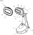
Fig 2 ] Lafigure 2 est une vue en perspective de l'appareil de lafigure 1 sur laquelle l'accessoire est illustré démonté du corps de l'appareil ; - [
Fig 3 ] Lafigure 3 est une vue de côté de l'appareil de lafigure 1 démuni de son accessoire ; - [
Fig 4 ] Lafigure 4 est une vue en coupe longitudinale de l'appareil de lafigure 1 ; - [
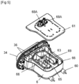
Fig 5 ] Lafigure 5 est une vue en perspective éclatée du corps chauffant équipant l'appareil de lafigure 1 ; - [
Fig 6 ] Lafigure 6 est une vue en perspective éclatée de l'accessoire équipant l'appareil de lafigure 1 ; - [
Fig 7 ] Lafigure 7 est une autre vue en perspective éclatée de l'accessoire équipant l'appareil de lafigure 1 ; - Seuls les éléments nécessaires à la compréhension de l'invention ont été représentés. Pour faciliter la lecture des dessins, les mêmes éléments portent les mêmes références d'une figure à l'autre.
- On notera que dans ce document, les termes "horizontal", "vertical", "inférieur", "supérieur", « haut », « bas », "avant", "arrière", « longitudinal », « transversal », employés pour décrire l'appareil font référence à cet appareil lorsqu'il repose à plat sur son embase.
- La
figure 1 représente un appareil de défroissage comportant un corps présentant un boîtier portatif en matière plastique comprenant une embase 1 surmontée d'une poignée 2 et d'une tête 3 d'émission de vapeur, l'embase 1 comprenant une face inférieure plane sur laquelle l'appareil de défroissage peut venir reposer stablement dans une position sensiblement verticale. - L'embase 1 de l'appareil de défroissage comporte un cordon 10 d'alimentation électrique permettant son raccordement à un réseau électrique domestique, et la tête 3 d'émission de vapeur comporte une face arrière munie d'un bouton 12 (visible sur la
figure 4 ) permettant de mettre sous tension l'appareil de défroissage. - L'embase 1 renferme une pompe 4 électrique, visible sur la
figure 4 , dont le fonctionnement est commandé au moyen d'une gâchette 5 disposée au sommet de la poignée 2, la gâchette 5 actionnant, de manière connue en soi, un interrupteur relié à une carte électronique de pilotage de la pompe 4, non représentés sur les figures. La pompe 4 est alimentée en liquide par un réservoir 11 ménagé dans l'embase 1, ce réservoir 11 étant avantageusement amovible de l'appareil de défroissage pour faciliter son remplissage. - La tête 3 d'émission de vapeur présente une forme élancée s'étendant transversalement à la direction longitudinale de la poignée 2 et comporte une extrémité longitudinale munie d'une face de traitement 30 destinée à venir verticalement en regard d'un vêtement à défroisser.
- Conformément aux
figures 1 à 3 , la face de traitement 30 comporte une protubérance 34 qui fait saillie sur le corps et qui comprend une extrémité supportant une surface chaude 31, de préférence métallique et de forme oblongue. - La protubérance 34 comporte également une série d'orifices de sortie de vapeur 33 disposés dans le fond d'une rainure ménagée au voisinage du pourtour de la protubérance 34. La protubérance 34 occupe avantageusement une position centrale sur la face de traitement 30 et présente une forme légèrement tronconique. La face de traitement 30 présente, au pied de la protubérance 34, une surface périphérique 32 qui s'étend parallèlement à la surface chaude 31 et forme un épaulement s'étendant jusqu'en bordure du corps de la tête 3.
- De manière préférentielle, la surface périphérique 32 est réalisée par une pièce métallique qui est rapportée à l'extrémité de la tête 3 et qui est en contact thermique avec un corps chauffant 6, visible sur les
figures 4 et5 , ménagé à l'intérieur de la tête 3. - Le corps chauffant 6 présente une forme générale en parallélépipède rectangle et comprend, de manière connue en soi, une fonderie, par exemple en aluminium, et un élément résistif chauffant 60, tel qu'une résistance électrique, cintré en U et intégré dans la fonderie.
- Le corps chauffant 6 comprend une face avant venant au contact thermique de la surface chaude 31, l'extrémité avant du corps chauffant 6 s'étendant à l'intérieur de la protubérance 34. De cette manière, la surface chaude 31 est chauffée par conduction thermique au travers de la protubérance 34.
- Le corps chauffant 6 comporte également un couvercle 61 qui repose, de manière étanche, sur la fonderie, et une chambre de vaporisation instantanée 63 délimitée par la fonderie et le couvercle 61. La fonderie comporte plus particulièrement une paroi périphérique sur laquelle repose le couvercle 61 et qui délimite latéralement la chambre de vaporisation instantanée 63.
- Avantageusement, l'alimentation de l'élément résistif chauffant 60 est régulée au moyen d'un thermostat 9 (visible sur la
figure 4 ) autour d'une température de consigne, mesurée au centre de la chambre de vaporisation instantanée 63, par exemple comprise entre 110°C et 150°C. - Le couvercle 61 comporte deux orifices d'injection d'eau 68A débouchant dans la chambre de vaporisation instantanée 63 au voisinage de l'extrémité avant de cette dernière, les deux orifices d'injection d'eau 68A étant reliés à la pompe 4 par l'intermédiaire d'un conduit d'acheminement de fluide (non représenté sur les figures).
- La chambre de vaporisation instantanée 63 comporte une paroi de fond formant une surface de vaporisation sur laquelle le liquide injecté via les deux orifices d'injection d'eau 68A est vaporisé et comporte un passage 65 pour la sortie de vapeur prévue sur la paroi périphérique, à l'opposé de la face de traitement 30.
- L'appareil de défroissage comporte en outre plusieurs parois de déviation 69 s'étendant dans la chambre de vaporisation instantanée 63 entre la zone où est injectée l'eau sur la paroi de fond et le passage 65 pour la sortie de la vapeur. Ces parois de déviation 69 forment des chicanes configurées pour dévier le flux de vapeur généré dans la chambre de vaporisation instantanée 63 et retenir les éventuelles gouttelettes d'eau pouvant être transportées par le flux de vapeur.
- Le corps chauffant 6 comporte également un circuit de distribution de vapeur 66 dans lequel est destiné à s'écouler le flux de vapeur provenant de la chambre de vaporisation instantanée 63. Selon le mode de réalisation représenté sur les figures, le circuit de distribution de vapeur 66 est disposé autour de la chambre de vaporisation instantanée 63.
- Le circuit de distribution de vapeur 66 est relié fluidiquement d'une part à la chambre de vaporisation instantanée 63 via le passage 65 pour la sortie de la vapeur, et d'autre part aux orifices de sortie de vapeur 33 via des conduits 36 prévus dans la face avant du corps chauffant 6. Le circuit de distribution de vapeur 66 est ainsi configuré pour alimenter en vapeur les orifices de sortie de vapeur 33. En particulier, la vapeur sortant de la chambre de vaporisation instantanée 63 par le passage 65 peut s'écouler dans le circuit de distribution de vapeur 66, de part et d'autre de la chambre de vaporisation instantanée 63 pour être ensuite diffusée au travers des conduits, ces derniers débouchant dans une chambre de distribution 35 ménagée en amont des orifices de sortie de vapeur 33 visible sur la
figure 4 . - Plus particulièrement selon l'invention et conformément aux
figures 1 et2 , l'appareil comporte un ou plusieurs accessoires 7 destinés à être monté de manière amovible contre la surface périphérique 32 de la tête 3, chaque accessoire 7 présentant une ouverture traversante 70 adaptée pour permettre le passage de la protubérance 34 lorsque l'accessoire 7 repose contre la surface périphérique 32. - L'accessoire 7 présente avantageusement une forme oblongue dont le contour externe épouse la forme du contour externe du corps de la tête 3, l'ouverture traversante 70 étant disposée en position centrale et présentant une forme épousant la forme du contour externe de la protubérance 34 de manière à ce que l'insertion de la protubérance 34 dans l'ouverture traversante 70 assure le centrage de l'accessoire 7 sur la tête 3.
- Conformément aux
figures 6 et7 , l'accessoire 7 comporte un corps central 71 en matière plastique comprenant quatre inserts métalliques 72, répartis de part et d'autre de l'ouverture traversante 70, et comporte un premier flasque 73 et un deuxième flasque 74 qui viennent se clipser sur deux faces opposées du corps central 71 de l'accessoire 7, en venant masquer les inserts métalliques 72. - De manière préférentielle, le premier flasque 73 est recouvert d'un premier revêtement qui définit une première surface de traitement 75 et le deuxième flasque 74 est recouvert d'un deuxième revêtement, de préférence différent du premier revêtement, qui définit une deuxième surface de traitement 76.
- Dans l'exemple illustré sur les figures, la première surface de traitement 75 est une plaque métallique qui est apposée sur la face externe du premier flasque 73. La plaque métallique est avantageusement fixée par des pattes 75A qui sont repliées derrière le premier flasque 73. La deuxième surface de traitement 76 est un textile, tel un velours ou une microfibre, qui est apposée sur la face externe du deuxième flasque 74. Le textile est fixé à l'aide de deux bagues de maintien 76A,76B qui sont respectivement rapportées au niveau du bord périphérique et de l'ouverture traversante 70 du deuxième flasque 74.
- De manière préférentielle, et comme cela est bien visible sur la
figure 3 , l'épaisseur de l'accessoire 7 correspondant sensiblement à la hauteur de la protubérance 34 de manière à ce que l'une des surfaces de traitement 75, 76 vienne dans le prolongement de la surface chaude 31 lorsque l'autre surface de traitement 76, 75 de l'accessoire 7 repose en appui contre la surface périphérique 32 de la tête 3. - Afin d'assurer un maintien magnétique du ou des accessoires 7 sur la tête 3, la tête 3 comprend quatre aimants 37 disposés derrière la surface périphérique 32, et illustrés en pointillés sur la
figure 2 , les aimants 37 étant disposés de manière à venir en regard des inserts métalliques 72 portés par l'accessoire 7 lorsque ce dernier est mis en place sur la tête 3. - L'appareil ainsi réalisé présente l'avantage de posséder un accessoire 7 qui est très ergonomique à mettre en place et à retirer la tête 3 de l'appareil.
- En effet, l'utilisateur peut mettre en place l'accessoire 7 sur la tête 3 simplement en alignant la protubérance 34 avec l'ouverture traversante 70 de l'accessoire 7, et en engageant l'accessoire 7 sur la tête 3 de manière à venir appliquer l'une des surfaces de traitement 75, 76 contre la surface périphérique 32.
- Lorsque l'accessoire 7 est disposé dans cette position, les aimants 37 de la tête 3 exercent une attraction magnétique sur les inserts métalliques 72 de sorte que l'accessoire 7 est maintenu en position sur la tête 3.
- L'utilisateur peut alors utiliser l'appareil en actionnant la gâchette 5 de l'appareil, pour provoquer la mise en marche de la pompe 4 et l'envoi d'eau dans la chambre de vaporisation 63, provoquant la sortie de vapeur par les orifices de sortie de vapeur 33.
- Lors de cette utilisation, l'accessoire 7 présente alors une surface de traitement 75, 76 qui est disposée tout autour de la surface chaude 31 et des orifices de sortie de vapeur 33 de sorte que la surface de traitement 75, 76 procure la même efficacité de traitement quel que soit le sens de déplacement de la tête 3 parallèlement au vêtement.
- De plus, l'utilisateur à la possibilité de choisir, parmi les deux surfaces de traitement 75, 76 de l'accessoire, celle qu'il va utiliser pour traiter son vêtement. Ainsi, il peut choisir de mettre l'accessoire 7 sur la tête 3 de telle sorte que ce soit la première surface de traitement 75 ou la deuxième surface de traitement 76 qui se retrouve exposée autour de la surface chaude 31.
- Ainsi, s'il dispose l'accessoire 7 de telle sorte que la première surface de traitement 75 se trouve appliquée contre la surface périphérique 32, alors la deuxième surface de traitement 76 va se retrouver être la surface active qui va venir au contact du vêtement. A l'inverse, lorsque l'utilisateur dispose l'accessoire 7 de telle sorte que la deuxième surface de traitement 76 se trouve appliquée contre la surface périphérique 32, alors la première surface de traitement 75 va se retrouver être la surface active qui va venir au contact du vêtement.
- Un tel appareil présente donc l'avantage, avec un nombre d'accessoires 7 limité, de proposer une plus grande diversité de surfaces de traitement.
- En particulier, lorsque l'utilisateur dispose l'accessoire 7 de telle sorte que la première surface de traitement 75, constituée par la plaque métallique, se trouve orientée en direction du vêtement à traiter, l'appareil bénéficie de toute la surface de la plaque métallique de l'accessoire 7, en plus de surface chaude 31, pour venir chauffer le vêtement, la surface métallique de l'accessoire 7 se trouvant alors chauffée par rayonnement et par conduction thermique avec la protubérance 34 et la surface périphérique 32 .
- A l'inverse, lorsque l'utilisateur dispose l'accessoire 7 de telle sorte que la deuxième surface de traitement 76, constituée par une surface textile, se trouve orientée en direction du vêtement à traiter, l'appareil peut être utilisé en bénéficiant des propriétés de cette surface pour venir agir sur le vêtement.
- Si cette surface est constituée par un velours, ce dernier exercera une traction sur le vêtement, lors du déplacement latéral de la tête de défroissage le long du vêtement, qui contribuera à améliorer la performance de défroissage.
- Si cette surface est constituée par une microfibre, cette dernière présentera l'avantage d'être très efficace pour enlever la poussière ou les saletés qui peuvent être accrochées à un vêtement.
- On obtient ainsi un appareil qui permet la réalisation de différents types de travaux de façon optimisée tout en présentant un encombrement et un cout réduit, du fait du faible nombre d'accessoires accompagnant l'appareil.
- Bien entendu, l'invention n'est nullement limitée au mode de réalisation décrit et illustré qui n'a été donné qu'à titre d'exemple. Des modifications restent possibles, notamment du point de vue de la constitution des divers éléments ou par substitution d'équivalents techniques, sans sortir pour autant du domaine de protection de l'invention, qui est définie par les revendications annexées.
- Ainsi, l'appareil pourra également comprendre plusieurs accessoires avec des surfaces de traitement différentes. A titre d'exemple, l'appareil pourra comprendre un premier accessoire avec une première surface de traitement constituée d'un velours et une deuxième surface de traitement constituée d'une microfibre. L'accessoire pourra également comporter un deuxième accessoire pour lesquelles les deux faces de traitement sont identiques et sont, par exemple, constituée par une plaque métallique
- Dans une variante de réalisation non représentée, l'accessoire pourra également être fixé sur la tête par un autre moyen de fixation que des moyens magnétiques, par exemple par clipsage.
- Dans une variante de réalisation non représentée, la surface chaude pourra également posséder son propre élément résistif, indépendant de la résistance chauffante du corps chauffant renfermant la chambre de vaporisation.
Claims (12)
- Appareil de défroissage comportant un corps comprenant une poignée (2) et une tête (3) d'émission de vapeur reliée à la poignée (2), la tête (3) d'émission de vapeur comportant une face de traitement (30) destinée à venir verticalement en regard d'un vêtement à défroisser, la face de traitement (30) comprenant au moins un orifice de sortie de vapeur (33) et une surface chaude (31) destinée à venir au contact du vêtement, l'appareil comportant en outre au moins un accessoire (7) destiné à être monté de manière amovible sur la tête (3) d'émission de vapeur, caractérisé en ce que la surface chaude (31) est disposée à l'extrémité d'une protubérance (34) qui fait saillie sur le corps, au niveau de la face de traitement (30), le corps comportant une surface périphérique (32) qui s'étend au pied de la protubérance (34) et en ce que l'accessoire (7) comprend une ouverture traversante (70) qui vient s'engager autour de ladite protubérance (34) lorsque l'accessoire (7) est monté sur la tête (3) d'émission de vapeur, l'accessoire (7) étant positionné devant la surface périphérique (32) et présentant au moins une surface de traitement (75, 76), s'étendant à la périphérie de l'ouverture traversante (70), destinée à venir au contact du vêtement.
- Appareil de défroissage selon la revendication 1, caractérisé en ce qu'il comporte un dispositif de fixation (37, 72) permettant de maintenir l'accessoire (7) sur la tête (3).
- Appareil de défroissage selon la revendication 2, caractérisé en ce que le dispositif de fixation (37, 72) comporte des moyens magnétiques assurant le maintien de l'accessoire (7) sur la face de traitement (30).
- Appareil de défroissage selon la revendication 3, caractérisé en ce que le corps comporte au moins un aimant disposé derrière la surface périphérique (32).
- Appareil de défroissage selon l'une quelconque des revendications 1 à 4, caractérisé en ce que l'accessoire (7) prend appui sur la surface périphérique (32) lorsqu'il est monté sur la tête (3) d'émission de vapeur.
- Appareil de défroissage selon l'une quelconque des revendications 1 à 5, caractérisé en ce que la surface chaude (31) est en contact thermique avec un corps chauffant (6) ménagé dans la tête (3).
- Appareil de défroissage selon la revendication 6, caractérisé en ce que le corps chauffant (6) renferme une chambre de vaporisation (63).
- Appareil de défroissage selon l'une quelconque des revendications 1 à 7, caractérisé en ce que la surface chaude (31) est métallique.
- Appareil de défroissage selon l'une quelconque des revendications 1 à 8, caractérisé en ce que la surface périphérique (32) s'étend parallèlement à la surface chaude (31).
- Appareil de défroissage selon l'une quelconque des revendications 1 à 9, caractérisé en ce que la surface de traitement (75, 76) s'étend sensiblement dans le plan de la surface chaude (31) lorsque l'accessoire (7) est monté sur la tête (3).
- Appareil de défroissage selon l'une quelconque des revendications 1 à 10, caractérisé en ce que l'accessoire (7) est réversible et comporte une première surface de traitement (75) et une deuxième surface de traitement (76) disposées sur deux faces opposées de l'accessoire (7).
- Appareil de défroissage selon la revendication 11, caractérisé en ce que la première surface de traitement (75) et la deuxième surface de traitement (76) présentent des états de surfaces et/ou des matériaux différents.
Applications Claiming Priority (1)
| Application Number | Priority Date | Filing Date | Title |
|---|---|---|---|
| FR2010645A FR3115298B1 (fr) | 2020-10-16 | 2020-10-16 | Appareil de defroissage portatif comportant un accessoire amovible |
Publications (3)
| Publication Number | Publication Date |
|---|---|
| EP3985166A1 EP3985166A1 (fr) | 2022-04-20 |
| EP3985166B1 true EP3985166B1 (fr) | 2024-02-21 |
| EP3985166C0 EP3985166C0 (fr) | 2024-02-21 |
Family
ID=73699102
Family Applications (1)
| Application Number | Title | Priority Date | Filing Date |
|---|---|---|---|
| EP21201314.8A Active EP3985166B1 (fr) | 2020-10-16 | 2021-10-06 | Appareil de defroissage portatif comportant un accessoire amovible |
Country Status (5)
| Country | Link |
|---|---|
| US (1) | US11732401B2 (fr) |
| EP (1) | EP3985166B1 (fr) |
| CN (1) | CN114381921A (fr) |
| ES (1) | ES2974425T3 (fr) |
| FR (1) | FR3115298B1 (fr) |
Families Citing this family (9)
| Publication number | Priority date | Publication date | Assignee | Title |
|---|---|---|---|---|
| FR3141192B1 (fr) * | 2022-10-20 | 2024-10-25 | Seb Sa | Accessoire de diffusion de vapeur |
| USD1073223S1 (en) * | 2023-04-17 | 2025-04-29 | Calor | Handheld steamer |
| USD1069283S1 (en) * | 2023-05-10 | 2025-04-01 | Yangping Zhong | Garment steamer |
| USD1069284S1 (en) * | 2023-05-25 | 2025-04-01 | Yangping Zhong | Garment steamer |
| USD1052204S1 (en) * | 2023-08-08 | 2024-11-19 | Yangping Zhong | Garment steamer |
| USD1011662S1 (en) * | 2023-08-25 | 2024-01-16 | Tingting Cheng | Garment steamer |
| JP1819915S (ja) * | 2024-01-08 | 2026-02-25 | 衣服ケア機用スチーマー | |
| USD1038555S1 (en) * | 2024-01-24 | 2024-08-06 | Shenzhen Pukaiyu Technology Co., Ltd. | Garment steamer |
| CN118621558A (zh) * | 2024-06-30 | 2024-09-10 | 集海科技(深圳)有限公司 | 熨烫机 |
Family Cites Families (19)
| Publication number | Priority date | Publication date | Assignee | Title |
|---|---|---|---|---|
| US3805425A (en) * | 1973-01-26 | 1974-04-23 | Rowenta Werke Gmbh | Brush devices |
| US5966851A (en) * | 1998-10-01 | 1999-10-19 | Serpa; Michael Lawrence | Safety pressing iron with burn prevention shield |
| US20010030183A1 (en) * | 2000-04-13 | 2001-10-18 | Bowen Lorelle Labarge | Piece Press Micro Iron With Swiveling Handle And Interchangeable Sole Plates |
| USD476160S1 (en) * | 2000-09-28 | 2003-06-24 | Goodway Electrical Co. Ltd. | Brush |
| FR2822480B1 (fr) | 2001-03-22 | 2003-12-26 | Rowenta Werke Gmbh | Accessoire pour fer a repasser |
| US20050278988A1 (en) * | 2004-04-26 | 2005-12-22 | Products Of Tomorrow, Inc. | Ironing device |
| US20100024492A1 (en) * | 2008-08-01 | 2010-02-04 | Anthony Kit Lun Leung | Compact steam appliance with folding handle |
| KR101104161B1 (ko) * | 2009-05-06 | 2012-01-13 | 한경희 | 전기스팀 다리미 |
| CN201598503U (zh) * | 2010-01-20 | 2010-10-06 | 漳州灿坤实业有限公司 | 一种蒸汽刷 |
| CN202744852U (zh) * | 2011-10-18 | 2013-02-20 | 皇家飞利浦电子股份有限公司 | 服装蒸汽挂烫机 |
| KR101515711B1 (ko) * | 2013-10-30 | 2015-04-27 | (주)에이타이드 | 스팀 다리미 |
| KR200488988Y1 (ko) * | 2014-12-08 | 2019-04-12 | 콘에어 코포레이션 | 이동식 휴대용 스팀다리미 장치 |
| CN106480693B (zh) * | 2016-11-21 | 2018-10-02 | 宁波凯波集团有限公司 | 一种超大蒸汽量的蒸汽发生器及多功能蒸汽刷 |
| FR3072100B1 (fr) * | 2017-10-05 | 2020-07-31 | Seb Sa | Appareil de defroissage equipe d'une chambre de vaporisation munie d'un orifice de nettoyage |
| CN207498690U (zh) * | 2017-10-11 | 2018-06-15 | 东保集团有限公司 | 一种挂烫机 |
| USD842559S1 (en) * | 2017-12-08 | 2019-03-05 | Lin Yang | Garment steamer |
| US10907300B2 (en) * | 2017-12-15 | 2021-02-02 | Shenzhen Chenbei Technology Co., Ltd. | Portable steamer with ironing arrangement |
| US10689795B2 (en) * | 2018-01-26 | 2020-06-23 | Ningbo Kaibo Group Co., Ltd. | Ironing head with auxiliary accessory |
| KR102043569B1 (ko) * | 2018-11-21 | 2019-11-11 | (주)넥스트업 | 스팀 진동 다리미 |
-
2020
- 2020-10-16 FR FR2010645A patent/FR3115298B1/fr active Active
-
2021
- 2021-10-06 ES ES21201314T patent/ES2974425T3/es active Active
- 2021-10-06 EP EP21201314.8A patent/EP3985166B1/fr active Active
- 2021-10-11 CN CN202111182776.6A patent/CN114381921A/zh active Pending
- 2021-10-13 US US17/499,973 patent/US11732401B2/en active Active
Also Published As
| Publication number | Publication date |
|---|---|
| CN114381921A (zh) | 2022-04-22 |
| EP3985166A1 (fr) | 2022-04-20 |
| FR3115298A1 (fr) | 2022-04-22 |
| EP3985166C0 (fr) | 2024-02-21 |
| FR3115298B1 (fr) | 2023-12-15 |
| ES2974425T3 (es) | 2024-06-27 |
| US20220120028A1 (en) | 2022-04-21 |
| US11732401B2 (en) | 2023-08-22 |
Similar Documents
| Publication | Publication Date | Title |
|---|---|---|
| EP3985168B1 (fr) | Appareil de defroissage portatif comportant un accessoire amovible | |
| EP3985166A1 (fr) | Appareil de defroissage portatif comportant un accessoire amovible | |
| EP3985164B1 (fr) | Appareil de defroissage portatif comportant une surface de traitement en textile | |
| FR2981371A1 (fr) | Fer a repasser comportant une chambre de vaporisation reliee a une cavite de recuperation du tartre comprenant un orifice de detartrage | |
| CA3252477A1 (fr) | Appareil de défroissage | |
| EP3572579B1 (fr) | Appareil de repassage équipé d'un accessoire de support | |
| EP3581702B1 (fr) | Appareil de traitement du linge a la vapeur comportant un dispositif support | |
| FR3072100A1 (fr) | Appareil de defroissage equipe d'une chambre de vaporisation munie d'un orifice de nettoyage | |
| FR2980218A1 (fr) | Fer a repasser comportant un dispositif pour projeter des gouttelettes de liquide a l'exterieur de la surface couverte par la semelle | |
| EP3581700B1 (fr) | Appareil de traitement du linge comportant une base munie d'un reservoir amovible | |
| EP3581704A1 (fr) | Appareil de traitement du linge à la vapeur comportant une planche de repassage | |
| EP3581703B1 (fr) | Appareil de traitement du linge à la vapeur comportant une planche de repassage | |
| FR3096992A1 (fr) | Appareil de traitement du linge à la vapeur | |
| EP4367314B1 (fr) | Appareil pour le traitement du linge a la vapeur comportant une base destinee a reposer sur un support | |
| EP4367315B1 (fr) | Appareil électroménager comportant un outil de repassage et/ou défroissage et une base portative reliée à l'outil par un cordon | |
| FR3137111A1 (fr) | Appareil électroménager de repassage et/ou défroissage comportant au moins deux chambres de vaporisation reliées entre elles par un conduit de liaison. | |
| FR3081477A1 (fr) | Fer a repasser equipe d'une chambre de vaporisation pourvue de nervures en forme de v | |
| WO2024223129A1 (fr) | Fer à repasser comprenant un générateur de vapeur | |
| WO2026012725A1 (fr) | Appareil de défroissage | |
| WO2025237882A1 (fr) | Appareil de défroissage comportant une plaque mobile | |
| EP4273316A1 (fr) | Appareil electromenager comportant un fer a repasser et une base reliee au fer a repasser par un cordon | |
| FR3162229A1 (fr) | Appareil de défroissage comportant une plaque mobile | |
| EP3985167A1 (fr) | Appareil de defroissage portatif comportant un dispositif de diffusion d'un additif | |
| FR2979923A1 (fr) | Fer a repasser comportant un circuit de distribution de vapeur comprenant une grille de filtration |
Legal Events
| Date | Code | Title | Description |
|---|---|---|---|
| PUAI | Public reference made under article 153(3) epc to a published international application that has entered the european phase |
Free format text: ORIGINAL CODE: 0009012 |
|
| STAA | Information on the status of an ep patent application or granted ep patent |
Free format text: STATUS: THE APPLICATION HAS BEEN PUBLISHED |
|
| AK | Designated contracting states |
Kind code of ref document: A1 Designated state(s): AL AT BE BG CH CY CZ DE DK EE ES FI FR GB GR HR HU IE IS IT LI LT LU LV MC MK MT NL NO PL PT RO RS SE SI SK SM TR |
|
| STAA | Information on the status of an ep patent application or granted ep patent |
Free format text: STATUS: REQUEST FOR EXAMINATION WAS MADE |
|
| 17P | Request for examination filed |
Effective date: 20221005 |
|
| RBV | Designated contracting states (corrected) |
Designated state(s): AL AT BE BG CH CY CZ DE DK EE ES FI FR GB GR HR HU IE IS IT LI LT LU LV MC MK MT NL NO PL PT RO RS SE SI SK SM TR |
|
| GRAP | Despatch of communication of intention to grant a patent |
Free format text: ORIGINAL CODE: EPIDOSNIGR1 |
|
| STAA | Information on the status of an ep patent application or granted ep patent |
Free format text: STATUS: GRANT OF PATENT IS INTENDED |
|
| RIC1 | Information provided on ipc code assigned before grant |
Ipc: D06F 75/30 20060101ALN20231004BHEP Ipc: D06F 75/38 20060101ALN20231004BHEP Ipc: D06F 73/00 20060101ALN20231004BHEP Ipc: D06F 87/00 20060101ALI20231004BHEP Ipc: D06F 75/20 20060101AFI20231004BHEP |
|
| INTG | Intention to grant announced |
Effective date: 20231023 |
|
| GRAS | Grant fee paid |
Free format text: ORIGINAL CODE: EPIDOSNIGR3 |
|
| GRAA | (expected) grant |
Free format text: ORIGINAL CODE: 0009210 |
|
| STAA | Information on the status of an ep patent application or granted ep patent |
Free format text: STATUS: THE PATENT HAS BEEN GRANTED |
|
| AK | Designated contracting states |
Kind code of ref document: B1 Designated state(s): AL AT BE BG CH CY CZ DE DK EE ES FI FR GB GR HR HU IE IS IT LI LT LU LV MC MK MT NL NO PL PT RO RS SE SI SK SM TR |
|
| REG | Reference to a national code |
Ref country code: GB Ref legal event code: FG4D Free format text: NOT ENGLISH |
|
| REG | Reference to a national code |
Ref country code: CH Ref legal event code: EP |
|
| REG | Reference to a national code |
Ref country code: DE Ref legal event code: R096 Ref document number: 602021009571 Country of ref document: DE |
|
| REG | Reference to a national code |
Ref country code: IE Ref legal event code: FG4D Free format text: LANGUAGE OF EP DOCUMENT: FRENCH |
|
| U01 | Request for unitary effect filed |
Effective date: 20240304 |
|
| U07 | Unitary effect registered |
Designated state(s): AT BE BG DE DK EE FI FR IT LT LU LV MT NL PT SE SI Effective date: 20240312 |
|
| REG | Reference to a national code |
Ref country code: ES Ref legal event code: FG2A Ref document number: 2974425 Country of ref document: ES Kind code of ref document: T3 Effective date: 20240627 |
|
| PG25 | Lapsed in a contracting state [announced via postgrant information from national office to epo] |
Ref country code: IS Free format text: LAPSE BECAUSE OF FAILURE TO SUBMIT A TRANSLATION OF THE DESCRIPTION OR TO PAY THE FEE WITHIN THE PRESCRIBED TIME-LIMIT Effective date: 20240621 |
|
| PG25 | Lapsed in a contracting state [announced via postgrant information from national office to epo] |
Ref country code: GR Free format text: LAPSE BECAUSE OF FAILURE TO SUBMIT A TRANSLATION OF THE DESCRIPTION OR TO PAY THE FEE WITHIN THE PRESCRIBED TIME-LIMIT Effective date: 20240522 |
|
| PG25 | Lapsed in a contracting state [announced via postgrant information from national office to epo] |
Ref country code: HR Free format text: LAPSE BECAUSE OF FAILURE TO SUBMIT A TRANSLATION OF THE DESCRIPTION OR TO PAY THE FEE WITHIN THE PRESCRIBED TIME-LIMIT Effective date: 20240221 Ref country code: RS Free format text: LAPSE BECAUSE OF FAILURE TO SUBMIT A TRANSLATION OF THE DESCRIPTION OR TO PAY THE FEE WITHIN THE PRESCRIBED TIME-LIMIT Effective date: 20240521 |
|
| PG25 | Lapsed in a contracting state [announced via postgrant information from national office to epo] |
Ref country code: RS Free format text: LAPSE BECAUSE OF FAILURE TO SUBMIT A TRANSLATION OF THE DESCRIPTION OR TO PAY THE FEE WITHIN THE PRESCRIBED TIME-LIMIT Effective date: 20240521 Ref country code: NO Free format text: LAPSE BECAUSE OF FAILURE TO SUBMIT A TRANSLATION OF THE DESCRIPTION OR TO PAY THE FEE WITHIN THE PRESCRIBED TIME-LIMIT Effective date: 20240521 Ref country code: IS Free format text: LAPSE BECAUSE OF FAILURE TO SUBMIT A TRANSLATION OF THE DESCRIPTION OR TO PAY THE FEE WITHIN THE PRESCRIBED TIME-LIMIT Effective date: 20240621 Ref country code: HR Free format text: LAPSE BECAUSE OF FAILURE TO SUBMIT A TRANSLATION OF THE DESCRIPTION OR TO PAY THE FEE WITHIN THE PRESCRIBED TIME-LIMIT Effective date: 20240221 Ref country code: GR Free format text: LAPSE BECAUSE OF FAILURE TO SUBMIT A TRANSLATION OF THE DESCRIPTION OR TO PAY THE FEE WITHIN THE PRESCRIBED TIME-LIMIT Effective date: 20240522 |
|
| PG25 | Lapsed in a contracting state [announced via postgrant information from national office to epo] |
Ref country code: PL Free format text: LAPSE BECAUSE OF FAILURE TO SUBMIT A TRANSLATION OF THE DESCRIPTION OR TO PAY THE FEE WITHIN THE PRESCRIBED TIME-LIMIT Effective date: 20240221 |
|
| PG25 | Lapsed in a contracting state [announced via postgrant information from national office to epo] |
Ref country code: PL Free format text: LAPSE BECAUSE OF FAILURE TO SUBMIT A TRANSLATION OF THE DESCRIPTION OR TO PAY THE FEE WITHIN THE PRESCRIBED TIME-LIMIT Effective date: 20240221 |
|
| PG25 | Lapsed in a contracting state [announced via postgrant information from national office to epo] |
Ref country code: SM Free format text: LAPSE BECAUSE OF FAILURE TO SUBMIT A TRANSLATION OF THE DESCRIPTION OR TO PAY THE FEE WITHIN THE PRESCRIBED TIME-LIMIT Effective date: 20240221 |
|
| PG25 | Lapsed in a contracting state [announced via postgrant information from national office to epo] |
Ref country code: CZ Free format text: LAPSE BECAUSE OF FAILURE TO SUBMIT A TRANSLATION OF THE DESCRIPTION OR TO PAY THE FEE WITHIN THE PRESCRIBED TIME-LIMIT Effective date: 20240221 |
|
| PG25 | Lapsed in a contracting state [announced via postgrant information from national office to epo] |
Ref country code: SK Free format text: LAPSE BECAUSE OF FAILURE TO SUBMIT A TRANSLATION OF THE DESCRIPTION OR TO PAY THE FEE WITHIN THE PRESCRIBED TIME-LIMIT Effective date: 20240221 |
|
| PG25 | Lapsed in a contracting state [announced via postgrant information from national office to epo] |
Ref country code: SM Free format text: LAPSE BECAUSE OF FAILURE TO SUBMIT A TRANSLATION OF THE DESCRIPTION OR TO PAY THE FEE WITHIN THE PRESCRIBED TIME-LIMIT Effective date: 20240221 Ref country code: SK Free format text: LAPSE BECAUSE OF FAILURE TO SUBMIT A TRANSLATION OF THE DESCRIPTION OR TO PAY THE FEE WITHIN THE PRESCRIBED TIME-LIMIT Effective date: 20240221 Ref country code: RO Free format text: LAPSE BECAUSE OF FAILURE TO SUBMIT A TRANSLATION OF THE DESCRIPTION OR TO PAY THE FEE WITHIN THE PRESCRIBED TIME-LIMIT Effective date: 20240221 Ref country code: CZ Free format text: LAPSE BECAUSE OF FAILURE TO SUBMIT A TRANSLATION OF THE DESCRIPTION OR TO PAY THE FEE WITHIN THE PRESCRIBED TIME-LIMIT Effective date: 20240221 |
|
| U20 | Renewal fee for the european patent with unitary effect paid |
Year of fee payment: 4 Effective date: 20240927 |
|
| REG | Reference to a national code |
Ref country code: DE Ref legal event code: R097 Ref document number: 602021009571 Country of ref document: DE |
|
| PLBE | No opposition filed within time limit |
Free format text: ORIGINAL CODE: 0009261 |
|
| STAA | Information on the status of an ep patent application or granted ep patent |
Free format text: STATUS: NO OPPOSITION FILED WITHIN TIME LIMIT |
|
| 26N | No opposition filed |
Effective date: 20241122 |
|
| REG | Reference to a national code |
Ref country code: CH Ref legal event code: PL |
|
| PG25 | Lapsed in a contracting state [announced via postgrant information from national office to epo] |
Ref country code: MC Free format text: LAPSE BECAUSE OF FAILURE TO SUBMIT A TRANSLATION OF THE DESCRIPTION OR TO PAY THE FEE WITHIN THE PRESCRIBED TIME-LIMIT Effective date: 20240221 |
|
| PG25 | Lapsed in a contracting state [announced via postgrant information from national office to epo] |
Ref country code: CH Free format text: LAPSE BECAUSE OF NON-PAYMENT OF DUE FEES Effective date: 20241031 |
|
| PGFP | Annual fee paid to national office [announced via postgrant information from national office to epo] |
Ref country code: TR Payment date: 20250926 Year of fee payment: 5 |
|
| PG25 | Lapsed in a contracting state [announced via postgrant information from national office to epo] |
Ref country code: IE Free format text: LAPSE BECAUSE OF NON-PAYMENT OF DUE FEES Effective date: 20241006 |
|
| U20 | Renewal fee for the european patent with unitary effect paid |
Year of fee payment: 5 Effective date: 20250926 |
|
| PGFP | Annual fee paid to national office [announced via postgrant information from national office to epo] |
Ref country code: GB Payment date: 20251023 Year of fee payment: 5 |
|
| PG25 | Lapsed in a contracting state [announced via postgrant information from national office to epo] |
Ref country code: CY Free format text: LAPSE BECAUSE OF FAILURE TO SUBMIT A TRANSLATION OF THE DESCRIPTION OR TO PAY THE FEE WITHIN THE PRESCRIBED TIME-LIMIT; INVALID AB INITIO Effective date: 20211006 |
|
| PGFP | Annual fee paid to national office [announced via postgrant information from national office to epo] |
Ref country code: ES Payment date: 20251110 Year of fee payment: 5 |
|
| PG25 | Lapsed in a contracting state [announced via postgrant information from national office to epo] |
Ref country code: HU Free format text: LAPSE BECAUSE OF FAILURE TO SUBMIT A TRANSLATION OF THE DESCRIPTION OR TO PAY THE FEE WITHIN THE PRESCRIBED TIME-LIMIT; INVALID AB INITIO Effective date: 20211006 |