EP3984924A1 - Conveyance device and method - Google Patents
Conveyance device and method Download PDFInfo
- Publication number
- EP3984924A1 EP3984924A1 EP20823230.6A EP20823230A EP3984924A1 EP 3984924 A1 EP3984924 A1 EP 3984924A1 EP 20823230 A EP20823230 A EP 20823230A EP 3984924 A1 EP3984924 A1 EP 3984924A1
- Authority
- EP
- European Patent Office
- Prior art keywords
- pads
- pad
- sliders
- rail
- slider
- Prior art date
- Legal status (The legal status is an assumption and is not a legal conclusion. Google has not performed a legal analysis and makes no representation as to the accuracy of the status listed.)
- Withdrawn
Links
Images



Classifications
-
- B—PERFORMING OPERATIONS; TRANSPORTING
- B65—CONVEYING; PACKING; STORING; HANDLING THIN OR FILAMENTARY MATERIAL
- B65G—TRANSPORT OR STORAGE DEVICES, e.g. CONVEYORS FOR LOADING OR TIPPING, SHOP CONVEYOR SYSTEMS OR PNEUMATIC TUBE CONVEYORS
- B65G47/00—Article or material-handling devices associated with conveyors; Methods employing such devices
- B65G47/74—Feeding, transfer, or discharging devices of particular kinds or types
- B65G47/84—Star-shaped wheels or devices having endless travelling belts or chains, the wheels or devices being equipped with article-engaging elements
- B65G47/846—Star-shaped wheels or wheels equipped with article-engaging elements
-
- A—HUMAN NECESSITIES
- A61—MEDICAL OR VETERINARY SCIENCE; HYGIENE
- A61F—FILTERS IMPLANTABLE INTO BLOOD VESSELS; PROSTHESES; DEVICES PROVIDING PATENCY TO, OR PREVENTING COLLAPSING OF, TUBULAR STRUCTURES OF THE BODY, e.g. STENTS; ORTHOPAEDIC, NURSING OR CONTRACEPTIVE DEVICES; FOMENTATION; TREATMENT OR PROTECTION OF EYES OR EARS; BANDAGES, DRESSINGS OR ABSORBENT PADS; FIRST-AID KITS
- A61F13/00—Bandages or dressings; Absorbent pads
- A61F13/15—Absorbent pads, e.g. sanitary towels, swabs or tampons for external or internal application to the body; Supporting or fastening means therefor; Tampon applicators
- A61F13/15577—Apparatus or processes for manufacturing
- A61F13/15764—Transferring, feeding or handling devices; Drives
-
- B—PERFORMING OPERATIONS; TRANSPORTING
- B65—CONVEYING; PACKING; STORING; HANDLING THIN OR FILAMENTARY MATERIAL
- B65G—TRANSPORT OR STORAGE DEVICES, e.g. CONVEYORS FOR LOADING OR TIPPING, SHOP CONVEYOR SYSTEMS OR PNEUMATIC TUBE CONVEYORS
- B65G47/00—Article or material-handling devices associated with conveyors; Methods employing such devices
- B65G47/22—Devices influencing the relative position or the attitude of articles during transit by conveyors
- B65G47/24—Devices influencing the relative position or the attitude of articles during transit by conveyors orientating the articles
- B65G47/248—Devices influencing the relative position or the attitude of articles during transit by conveyors orientating the articles by turning over or inverting them
-
- B—PERFORMING OPERATIONS; TRANSPORTING
- B65—CONVEYING; PACKING; STORING; HANDLING THIN OR FILAMENTARY MATERIAL
- B65G—TRANSPORT OR STORAGE DEVICES, e.g. CONVEYORS FOR LOADING OR TIPPING, SHOP CONVEYOR SYSTEMS OR PNEUMATIC TUBE CONVEYORS
- B65G47/00—Article or material-handling devices associated with conveyors; Methods employing such devices
- B65G47/22—Devices influencing the relative position or the attitude of articles during transit by conveyors
- B65G47/26—Devices influencing the relative position or the attitude of articles during transit by conveyors arranging the articles, e.g. varying spacing between individual articles
-
- B—PERFORMING OPERATIONS; TRANSPORTING
- B65—CONVEYING; PACKING; STORING; HANDLING THIN OR FILAMENTARY MATERIAL
- B65G—TRANSPORT OR STORAGE DEVICES, e.g. CONVEYORS FOR LOADING OR TIPPING, SHOP CONVEYOR SYSTEMS OR PNEUMATIC TUBE CONVEYORS
- B65G47/00—Article or material-handling devices associated with conveyors; Methods employing such devices
- B65G47/22—Devices influencing the relative position or the attitude of articles during transit by conveyors
- B65G47/26—Devices influencing the relative position or the attitude of articles during transit by conveyors arranging the articles, e.g. varying spacing between individual articles
- B65G47/28—Devices influencing the relative position or the attitude of articles during transit by conveyors arranging the articles, e.g. varying spacing between individual articles during transit by a single conveyor
-
- B—PERFORMING OPERATIONS; TRANSPORTING
- B65—CONVEYING; PACKING; STORING; HANDLING THIN OR FILAMENTARY MATERIAL
- B65G—TRANSPORT OR STORAGE DEVICES, e.g. CONVEYORS FOR LOADING OR TIPPING, SHOP CONVEYOR SYSTEMS OR PNEUMATIC TUBE CONVEYORS
- B65G47/00—Article or material-handling devices associated with conveyors; Methods employing such devices
- B65G47/22—Devices influencing the relative position or the attitude of articles during transit by conveyors
- B65G47/26—Devices influencing the relative position or the attitude of articles during transit by conveyors arranging the articles, e.g. varying spacing between individual articles
- B65G47/30—Devices influencing the relative position or the attitude of articles during transit by conveyors arranging the articles, e.g. varying spacing between individual articles during transit by a series of conveyors
- B65G47/32—Applications of transfer devices
-
- B—PERFORMING OPERATIONS; TRANSPORTING
- B65—CONVEYING; PACKING; STORING; HANDLING THIN OR FILAMENTARY MATERIAL
- B65G—TRANSPORT OR STORAGE DEVICES, e.g. CONVEYORS FOR LOADING OR TIPPING, SHOP CONVEYOR SYSTEMS OR PNEUMATIC TUBE CONVEYORS
- B65G47/00—Article or material-handling devices associated with conveyors; Methods employing such devices
- B65G47/74—Feeding, transfer, or discharging devices of particular kinds or types
- B65G47/84—Star-shaped wheels or devices having endless travelling belts or chains, the wheels or devices being equipped with article-engaging elements
- B65G47/846—Star-shaped wheels or wheels equipped with article-engaging elements
- B65G47/847—Star-shaped wheels or wheels equipped with article-engaging elements the article-engaging elements being grippers
-
- B—PERFORMING OPERATIONS; TRANSPORTING
- B65—CONVEYING; PACKING; STORING; HANDLING THIN OR FILAMENTARY MATERIAL
- B65G—TRANSPORT OR STORAGE DEVICES, e.g. CONVEYORS FOR LOADING OR TIPPING, SHOP CONVEYOR SYSTEMS OR PNEUMATIC TUBE CONVEYORS
- B65G47/00—Article or material-handling devices associated with conveyors; Methods employing such devices
- B65G47/74—Feeding, transfer, or discharging devices of particular kinds or types
- B65G47/84—Star-shaped wheels or devices having endless travelling belts or chains, the wheels or devices being equipped with article-engaging elements
- B65G47/846—Star-shaped wheels or wheels equipped with article-engaging elements
- B65G47/848—Star-shaped wheels or wheels equipped with article-engaging elements the article-engaging elements being suction or magnetic means
-
- B—PERFORMING OPERATIONS; TRANSPORTING
- B65—CONVEYING; PACKING; STORING; HANDLING THIN OR FILAMENTARY MATERIAL
- B65G—TRANSPORT OR STORAGE DEVICES, e.g. CONVEYORS FOR LOADING OR TIPPING, SHOP CONVEYOR SYSTEMS OR PNEUMATIC TUBE CONVEYORS
- B65G2201/00—Indexing codes relating to handling devices, e.g. conveyors, characterised by the type of product or load being conveyed or handled
- B65G2201/02—Articles
- B65G2201/0214—Articles of special size, shape or weigh
- B65G2201/022—Flat
-
- B—PERFORMING OPERATIONS; TRANSPORTING
- B65—CONVEYING; PACKING; STORING; HANDLING THIN OR FILAMENTARY MATERIAL
- B65G—TRANSPORT OR STORAGE DEVICES, e.g. CONVEYORS FOR LOADING OR TIPPING, SHOP CONVEYOR SYSTEMS OR PNEUMATIC TUBE CONVEYORS
- B65G2811/00—Indexing codes relating to common features for more than one conveyor kind or type
- B65G2811/09—Driving means for the conveyors
- B65G2811/095—Speed variation control means
Definitions
- the present invention relates to conveying apparatus and method that mainly convey a finished article, a half-finished article, a part, or the like of a wearable article while varying the speed thereof.
- This kind of conveying apparatus includes a plurality of pads, and receives workpieces from an upstream side in a reception position by the pads and delivers the workpieces to a downstream side in a delivery position. Variations in pad conveyance speed between the reception and delivery cause variations in the space between the workpieces between the reception position and the delivery position.
- This kind of conveying apparatus usually includes a large number of pads that are driven and rotated by a rotating shaft, a supporting ring that is rotatably supported around the rotating shaft and supports the pads in such a way that the pads move in a predetermined orbit, and a guide mechanism that is provided between the pads and the rotating shaft and guides the relative movement of the pads and the supporting ring.
- a large number of sliders whose number is the same as that of pads, are mounted on a rail of the guide mechanism so as to be slidable in a circumferential direction. Each slider is guided by the rail and is accelerated and decelerated in the circumferential direction together with the pad by a variable speed mechanism (PTL 1).
- PTL 1 variable speed mechanism
- PTL 1 WO 2018/011905 ( FIG. 4 )
- the sliders of the guide mechanism guiding the pads are placed in positions closer to an inner circumferential side than the pads. Consequently, the distance between adjacent sliders is smaller than the distance between adjacent pads, which makes the adjacent sliders tend to interfere with each other.
- an object of the present invention is to make it possible to increase the number of workpieces that can be conveyed by a conveying apparatus per unit time by narrowing the pitch between workpieces in the conveying apparatus provided with a variable speed mechanism and in a conveying method and thereby support high-speed processing.
- the apparatus of the present invention includes: a rotating shaft 10;
- the method of the present invention includes: a step of conveying in which the first and second pads 1 and 2 convey the workpieces W with speeds of the first and second pads 1 and 2 being varied;
- the first and second pads 1 and 2 are adjacent to each other in the circumferential direction R, and the first sliders are individually provided for the first pads 1 and the second sliders are individually provided for the second pads 2. That is, the first and second sliders are adjacent to each other in the circumferential direction R, are separated from each other in the axial direction S, and overlap each other in a part in the circumferential direction during deceleration. This makes it possible to reduce the pitch between the first and second pads 1 and 2 that are adjacent to each other in the circumferential direction R.
- each slider so as to be long in the circumferential direction, which stabilizes an orbiting operation of each pad.
- the apparatus of the present invention includes: first pads 1 and second pads 2 arranged around an axis 10S, the first and second pads orbiting along an orbit with their speeds being varied, the first and second pads being alternately arranged so as to be adjacent to each other in a circumferential direction R and each holding a workpiece W;
- the method of the present invention includes: a step in which the first and second pads 1 and 2 convey the workpieces W with speeds of the first and second pads 1 and 2 being varied;
- the first and second sliders provided for each of the first and second pads 1 and 2 that are adjacent to each other in the circumferential direction R are separated from each other in the axial direction S; therefore, the first slider of the first pad and the second slider of the second pad, each having a long contact length by which each slider is in contact with the rail, can overlap each other in a part in the circumferential direction during deceleration. This makes it possible to reduce the pitch between the first and second pads that are adjacent to each other in the circumferential direction.
- the contact length by which the first or second slider is in contact with the rail means the length, from one circumferential end to the other circumferential end, of the first (or second) slider supporting one pad.
- first and second rails 1L and 2L are attached to one supporting ring 3.
- the supporting ring 3 includes a first surface IF which is one-side surface in the axial direction S and a second surface 2F which is the other-side surface in the axial direction S, and the first rail 1L and the second rail 2L are attached to the first surface IF and the second surface 2F, respectively.
- a guide mechanism including a supporting ring, a rail, and a slider is likely to be compact.
- the first rail 1L and the second rail 2L are each formed in a shape of an endless loop.
- a pair of the first rails 1L is provided in such a way that the first rails 1L are separated from each other in the axial direction S and a pair of the second rails 2L is provided in such a way that the second rails 2L are separated from each other in the axial direction S, the first sliders IS are provided for each rail of the first rails 1L, and the second sliders 2S are provided for each rail of the second rails 2L.
- the conveying apparatus further includes a tubular portion 31 that rotatably supports the rotating shaft, and the supporting ring 3 is rotatably supported on the tubular portion 31.
- the supporting ring 3 rotates with the pads at high speeds and each slider reciprocates in response to variations in speed. This makes each slider and each rail less likely to be worn away and increases durability thereof.
- a step in which the first pads 1 and the second pads 2 receive the workpieces W from an upstream apparatus and the first pads 1 and the second pads 2 deliver the workpieces W to a downstream apparatus in the moving and separating step a step in which the first pads 1 and the second pads 2 receive the workpieces W from an upstream apparatus and the first pads 1 and the second pads 2 deliver the workpieces W to a downstream apparatus in the moving and separating step.
- the number of the first sliders IS is larger than the number of the second sliders 2S, and, for each of the second pads 2, the number of the first sliders IS is smaller than the number of the second sliders 2S.
- first and second sliders After making the shapes and sizes of the first and second sliders uniform, it is possible to set the first and second sliders so as to have the aforementioned contact length relationship only by a difference in the number of first or second sliders supporting each pad.
- each of the first pads 1 may be supported by two first sliders IS and one second slider 2S and each of the second pads 2 may be supported by one first slider IS and two second sliders 2S.
- a first length L1 of each of the first pads 1 in the circumferential direction R is shorter than the first contact length L11 and longer than the second contact length L12, and a second length L2 of each of the second pads 2 in the circumferential direction R is longer than the third contact length L21 and shorter than the fourth contact length L22.
- a slider having a contact length longer than the length of each pad in the circumferential direction achieves stable orbiting of the pad.
- the present manufacturing apparatus includes an upstream roll (an upstream apparatus) 4, a variable speed conveying apparatus 5, and a downstream roll (a downstream apparatus) 6.
- the variable speed conveying apparatus 5 includes a plurality of first and second pads 1 and 2 alternately in a circumferential direction R. The above-mentioned rolls 4 and 6 and the pads 1 and 2 for holding convey workpieces W.
- the pads 1 and 2 for holding rotate along the orbit of the variable speed conveying apparatus 5 with the speeds of the pads 1 and 2 being varied, and receive the workpieces W from the upstream roll 4 in a reception position P1 and deliver the workpieces W onto the downstream roll 6 in a delivery position P2.
- variable speed mechanism 20 is provided for each of the pads 1 and 2 and accelerates and decelerates each of the pads 1 and 2 while the pads 1 and 2 are orbiting.
- crank arms 22 are arranged on one driving wheel 21 with an equiangular pitch.
- the space between the crank arms 22 is unchangeable, and arm centers 220, which are the rotation centers of these crank arms 22, rotate with the driving wheel 21 at the same angular speed.
- the driving wheel 21 rotates with a rotating shaft 10 in the circumferential direction R at a constant angular speed.
- a cam roller 223 for varying speed is provided in a position separated from the arm center 220 of each crank arm 22, and the cam roller 223 moves along a cam groove 44 for varying speed of FIG. 2 .
- the cam groove 44 for varying speed is eccentric with respect to a center of drive 210, which is the rotation center of the driving wheel 21, and is immovable.
- the distance from the center of drive 210 to the cam roller 223 periodically increases and reduces depending on the positions of the cam roller 223 and the cam groove 44.
- each crank arm 22 of FIG. 1 periodically swings within a given angular range and the tip of the crank arm 22 periodically swings. That is, in the approximately left half of an area shown in FIG. 1 , the tip of each crank arm 22 is displaced from the arm center 220 of the crank arm 22 in a conveyance direction along the circumferential direction R; in the approximately right half of the area shown in FIG. 1 , the tip of each crank arm 22 is displaced in an opposite direction.
- a link lever 23 pin linked to the tip of each crank arm 22 and each of the first and second pads 1 and 2 pin linked to the link levers 23 are also displaced in conjunction with a swing of the tip of the crank arm 22. Due to the above-mentioned swing of each crank arm 22, the distance between the arm center 220 of the crank arm 22 and each of the pads 1 and 2 varies; therefore, the space between the first pad 1 and the second pad 2 that are adjacent to each other also varies. Consequently, the angular speeds of the first and second pads 1 and 2 for holding and the space between the pads 1 and 2 in the circumferential direction R vary.
- the guide mechanism 30 includes first and second sliders IS and 2S, first and second rails 1L and 2L, and a supporting ring 3 in the shape of a doughnut-shaped plate, which are shown in FIGS. 2 and 4 .
- the driving wheel 21 integrally rotates with the rotating shaft 10.
- the rotating shaft 10 is rotatably supported on the inner circumferential side of a tubular portion 31.
- the supporting ring 3 is rotatably supported on the outer periphery of the tubular portion 31.
- a driving force of an unillustrated motor may be input to the supporting ring 3 to make the supporting ring 3 rotate at a constant angular speed.
- first rail 1L and the second rail 2L are attached to a first surface IF which is one surface of each supporting ring 3 in the axial direction S and a second surface 2F which is the other surface in the axial direction S, respectively. Consequently, the first rail 1L and the second rail 2L are provided so as to be separated from each other in the axial direction S and parallel to each other. Moreover, a pair of first rails 1L is arranged such that the first rails 1L are parallel to each other, and a pair of second rails 2L is also arranged such that the second rails 2L are parallel to each other.
- each of the rails 1L and 2L is an endless annular ring (perfect circle). Only the first slider IS is slidably attached to the first rail 1L of FIG. 4(b) . On the other hand, only the second slider 2S is slidably attached to the second rail 2L.
- the sliders 1S and 2S and the rails 1L and 2L are placed in positions closer to the center of drive 210 than the pads 1 and 2. That is, the orbital paths of the sliders 1S and 2S are located in positions closer to an inner circumferential side than the orbital paths of the pads 1 and 2.
- the first sliders IS are provided for the respective first pads 1 in different positions from the second sliders 2S in the axial direction S of the rotating shaft 10 ( FIG. 2 ) and orbit with the first pads 1 with the speeds of the first sliders IS and the first pads being varied.
- the second sliders 2S are provided for the respective second pads 2 in different positions from the first sliders IS in the axial direction S of the rotating shaft 10 ( FIG. 2 ) and orbit with the second pads 2 with the speeds of the second sliders 2S and the second pads being varied.
- the above-mentioned first rail 1L of FIG. 2 supports the first pads 1 via the first sliders IS and the first bases 1B, and guides the first sliders IS and does not guide the second sliders 2S.
- the second rail 2L supports the second pads 2 via the second sliders 2S and the second bases 2B, and guides the second sliders 2S and does not guide the first sliders IS.
- each rail is formed so as to be convex in cross section and each slider is formed so as to be concave in cross section.
- each rail may be formed as a concave groove and each slider may be formed so as to be convex.
- a cam drum 32 may be fixed to the tubular portion 31.
- First and second cam grooves 41 and 42 that displace the pads 1 and 2, respectively, in the axial direction S are provided in the cam drum 32.
- first and second pads 1 and 2 are attached to the first and second bases 1B and 2B, respectively, in such a way that the first and second pads 1 and 2 can reciprocate in the axial direction S.
- first and second pads 1 and 2 include first and second cam followers 1C and 2C fitted into the first and second cam grooves 41 and 42, respectively.
- first and second pads 1 and 2 of FIG. 3A separate from each other in the circumferential direction R and also separate from each other in the axial direction S as shown in FIG. 3B while rotating in the circumferential direction R ( FIG. 1 ).
- the pads 1 and 2 have roughly triangular shapes facing in opposite directions and can approach each other in the circumferential direction R. Therefore, the first base 1B and the second base 2B of FIG. 3A approach each other in the reception position P1 of FIG. 1 , that is, at low speeds.
- the first and second sliders 1S and 2S of FIGS. 4(a) and (c) are relatively displaced to the extent that a part of the first slider IS and a part of the second slider 2S overlap each other in the circumferential direction R.
- This makes it possible to increase the length (size) of each of the sliders 1S and 2S in the circumferential direction R and thereby make stable guidance possible and, at the same time, to reduce the pitch between the above-mentioned pads 1 and 2 of FIG. 1 and thereby increase the number of pads 1 and 2.
- Variable speed conveyance of the workpieces includes the following steps: a conveying step, an accelerating step, a moving and separating step, a decelerating step, and a moving and approaching step.
- the first and second pads 1 and 2 of FIG. 1 receive the workpieces W from the upstream roll 4 in the reception position P1 by sucking the workpieces W and making them cling thereto by negative pressure.
- the first and second pads 1 and 2 that have received the workpieces W perform the step of conveying the workpieces W by orbiting with the speeds of the first and second pads 1 and 2 being varied.
- the first and second pads 1 and 2 of FIG. 1 return to the reception position P1 with the speeds thereof being varied. The following are detailed descriptions of these operations.
- the circumferential velocities of the first and second pads 1 and 2 that have received the workpieces W in the reception position P1 are accelerated by the variable speed mechanisms 20.
- the speeds of the pads 1 and 2 are gradually increased and the pitch between the first and second pads 1 and 2 that are adjacent to each other is increased; in this way, the moving and separating step is performed.
- variable speed mechanism 20 is well known per se and disclosed in, for example, WO 2018/011905 , the contents of which are incorporated herein in their entirety.
- the first and second pads 1 and 2 holding the workpieces W move and orbit in a state in which the distance between the first pad 1 and the second pad 2, whose speeds were increased by acceleration, is increased.
- first and second pads 1 and 2 separate in the circumferential direction R as shown in FIGS. 3A and 3B by being guided by the first and second cam grooves 41 and 42, respectively, of the cam drum 32 as shown in FIG. 2 , and then the distance between the first and second pads 1 and 2 is increased in the axial direction S.
- the first and second pads 1 and 2 of FIG. 1 arrive at the delivery position P2 abutting on the downstream roll 6 and deliver the workpieces W held thereby to the downstream roll 6.
- the circumferential velocities of the pads 1 and 2 may be in any one of the following states: the circumferential velocities of the pads 1 and 2 are being accelerated, the circumferential velocities of the pads 1 and 2 are being increased, and the circumferential velocities of the pads 1 and 2 are constant.
- the workpiece W When the workpieces W are delivered in a state in which they are separated in both the circumferential direction R and the axial direction S of FIG. 3 as described above, the workpiece W may be a panel placed in a main body portion of a disposable diaper. A method for placing such a panel is disclosed in WO 2017/056952 A1 , for example.
- the circumferential velocities of the first and second pads 1 and 2 of FIG. 1 are decelerated by the variable speed mechanisms 20 from the delivery position P2 until arrival at the reception position P1; in this way, the decelerating step is performed.
- the first and second pads 1 and 2 approach each other in the axial direction S along the first and second cam grooves 41 and 42 of FIG. 2 and approach each other in the circumferential direction R as shown in FIG. 3A .
- the first and second pads 1 and 2 When arriving at the reception position P1 in a state in which the first and second pads 1 and 2 of FIG. 1 approach each other in the circumferential direction R, the first and second pads 1 and 2 receive the workpieces W from the upstream roll 4.
- the pads 1 and 2 of FIG. 3A are also small in the circumferential direction R and the pads 1 and 2 can approach each other.
- the orbiting of the pads 1 and 2 is guided by the guide mechanism 30 of FIG. 4 .
- the first and second sliders 1S and 2S of the guide mechanism 30 of FIG. 4 need a certain length in the circumferential direction R in order to stabilize guidance of the pads in the circumferential direction R.
- the adjacent sliders 1S and 2S overlap each other in the circumferential direction R.
- a step is performed in which, in the reception position P1 of FIG. 4 , the first slider IS and the second slider 2S after deceleration overlap each other in a part in the circumferential direction R, which causes the first pad 1 and the second pad 2 of FIG. 5 to approach each other, and the first pad 1 and the second pad 2 move in this state in which they have approached each other.
- the first pad 1 and the second pad 2 receive the workpieces W from the upstream roll 4 in the reception position P1.
- the pads 1 and 2 may include mechanisms that make them turn around the normal to a drum after separating in the circumferential direction R. This mechanism is described in, for example, WO 2005/075163 , the contents of which are incorporated herein in their entirety.
- the rails 1L and 2L of FIGS. 5(b) and (c) may be arranged side by side on the outer circumferential surface of the supporting ring 3, not on the first surface IF or the second surface 2F of the supporting ring 3.
- the pads of the aforementioned embodiment are roughly triangular or pentagonal in shape; they may be square or rectangular in shape.
- first pad and the second pad may be completely identical in shape.
- each pad may include, for example, a machining apparatus such as an anvil. Furthermore, each pad may hold the workpiece by sucking the workpiece and making it cling thereto by negative pressure or may hold the workpiece by a needle, a hook, or the like.
- variable speed conveying apparatus 5 Next, another embodiment of the variable speed conveying apparatus 5 will be described.
- FIGS. 6 and 7 show the variable speed conveying apparatus 5 and the guide mechanism 30, respectively, of the other embodiment.
- variable speed conveying apparatus 5 includes a large number of first and second pads 1 and 2, a large number of first and second sliders IS and 2S, and first and second rails 1L and 2L.
- the first and second pads 1 and 2 are arranged around an axis 10S, orbit along an orbit with the speeds thereof being varied, are alternately arranged so as to be adjacent to each other in a circumferential direction R, and convey workpieces while holding them. Also in the present embodiment, as in the case of the aforementioned embodiment, the pads 1 and 2 rotate along the orbit of the variable speed conveying apparatus 5 with the speeds of the pads 1 and 2 being varied, and receive the workpieces (not shown in the drawing) from an unillustrated upstream roll in a reception position P1 and deliver the workpieces (not shown in the drawing) onto a downstream roll in a delivery position P2.
- the workpiece may be held by being sucked and made to cling to the outer surface of the pad.
- the first and second sliders 1S and 2S are provided for each of the first and second pads 1 and 2 in different positions in an axial direction S of the axis 10S and orbit with the first and second pads 1 and 2 with the speeds of the first and second sliders 1S and 2S being varied.
- the axis 10S is the axis of the rotating shaft 10 (see FIG. 2 ).
- the first rail 1L supports the first pads 1 or the second pads 2 via the first sliders 1S, and guides the first sliders IS and does not guide the second sliders 2S.
- the second rail 2L supports the first pads 1 or the second pads 2 via the second sliders 2S, and guides the second sliders 2S and does not guide the first sliders IS.
- the above-mentioned second rail 2L is arranged so as to be separated from the above-mentioned first rail 1L and parallel thereto. It is to be noted that, as in the case of the above-mentioned embodiment, the rails 1L and 2L are fixed to a supporting ring (not shown in the drawing) that is driven and rotated.
- the sliders 1S and 2S and the rails 1L and 2L are placed in positions closer to the axis 10S than the pads 1 and 2. That is, the orbital paths of the sliders 1S and 2S are located in positions closer to an inner circumferential side than the orbital paths of the pads 1 and 2.
- each first pad 1 is supported by two first sliders IS and one second slider 2S.
- each second pad 2 is supported by one first slider IS and two second sliders 2S.
- sliders 1S and 2S have the same or symmetrical shape and structure.
- the number of sliders supporting each of the pads 1 and 2 is set; therefore, for each first pad 1, a first contact length L11 by which the first sliders IS are in contact with the first rail 1L is longer than a second contact length L12 by which the second slider 2S is in contact with the second rail 2L. Moreover, for each second pad 2, a third contact length L21 by which the first slider IS is in contact with the first rail 1L is shorter than a fourth contact length L22 by which the second sliders 2S are in contact with the second rail 2L.
- a first length L1 of each first pad 1 mentioned above in the above-mentioned circumferential direction R is shorter than the first contact length L11 and longer than the second contact length L12.
- a second length L2 of each second pad 2 in the circumferential direction R is longer than the third contact length L21 and shorter than the fourth contact length L22.
- first pad 1 With two first sliders IS and one second slider 2S, which stabilizes support in the circumferential direction. Moreover, support of the second pad 2 in the circumferential direction is also stabilized in a similar manner.
- first sliders IS supporting the first pad 1 may be provided as one first slider IS which is long in the circumferential direction R.
- second sliders 2S supporting the second pad 2 may be provided as one second slider 2S which is long in the circumferential direction R.
- Variable speed conveyance of the workpieces includes the following steps: a conveying step, an accelerating step, a moving and separating step, a decelerating step, and a moving and approaching step.
- the first and second pads 1 and 2 of FIG. 6 receive the workpieces from the upstream roll in the reception position P1 by sucking the workpieces and making them cling thereto by negative pressure.
- the first and second pads 1 and 2 that have received the workpieces perform the step of conveying the workpieces by orbiting with the speeds of the first and second pads 1 and 2 being varied. Then, after delivering the workpieces to the downstream roll in the delivery position P2, the first and second pads 1 and 2 return to the reception position P1 with the speeds thereof being varied. The following are detailed descriptions of these operations.
- the circumferential velocities of the first and second pads 1 and 2 that have received the workpieces in the reception position P1 are accelerated by variable speed mechanisms 20.
- the speeds of the pads 1 and 2 are gradually increased and the pitch between the first and second pads 1 and 2 that are adjacent to each other is increased; in this way, the moving and separating step is performed.
- variable speed mechanism 20 is well known per se and disclosed in, for example, WO 2018/011905 , the contents of which are incorporated herein in their entirety.
- the circumferential velocities of the pads 1 and 2 may be in any one of the following states: the circumferential velocities of the pads 1 and 2 are being accelerated, the circumferential velocities of the pads 1 and 2 are being increased, and the circumferential velocities of the pads 1 and 2 are constant.
- the circumferential velocities of the first and second pads 1 and 2 are decelerated by variable speed mechanisms, which are similar to those described above, from the delivery position P2 until arrival at the reception position P1; in this way, the decelerating step is performed. During this deceleration, the first and second pads 1 and 2 approach each other in the circumferential direction R.
- the first and second pads 1 and 2 When arriving at the reception position P1 in a state in which the first and second pads 1 and 2 approach each other in the circumferential direction R, the first and second pads 1 and 2 receive the workpieces from the upstream roll.
- a step is performed in which, in the reception position P1 of FIG. 7 , the first slider IS and the second slider 2S after deceleration overlap each other in a part ⁇ in the circumferential direction R, which causes the first pad 1 and the second pad 2 of FIG. 6 to approach each other, and the first pad 1 and the second pad 2 move in this state in which they have approached each other.
- the first pad 1 and the second pad 2 receive the workpieces from the upstream roll in the reception position P1.
- the supporting ring there is no need for the supporting ring to rotate in synchronization with the rotating shaft.
- a supporting member which is not continuous in a circular fashion may be adopted in place of the supporting ring.
- the speed of each pad may be constant in the reception position from the start to end of reception.
- the upstream apparatus and the downstream apparatus may be conveyors and the like, not rolls.
- the present invention can be used in conveyance in the manufacture of parts and half-finished articles of these absorbent articles.
Landscapes
- Engineering & Computer Science (AREA)
- Mechanical Engineering (AREA)
- Health & Medical Sciences (AREA)
- Life Sciences & Earth Sciences (AREA)
- General Health & Medical Sciences (AREA)
- Biomedical Technology (AREA)
- Heart & Thoracic Surgery (AREA)
- Vascular Medicine (AREA)
- Manufacturing & Machinery (AREA)
- Animal Behavior & Ethology (AREA)
- Epidemiology (AREA)
- Public Health (AREA)
- Veterinary Medicine (AREA)
- Specific Conveyance Elements (AREA)
- Attitude Control For Articles On Conveyors (AREA)
- Absorbent Articles And Supports Therefor (AREA)
- Reciprocating Conveyors (AREA)
Abstract
overlap each other in a part in a circumferential direction, which causes the first pad and the second pad to approach each other, and the first pad and the second pad move and approach each other in this state in which the first pad and the second pad have approached each other.
Description
- The present invention relates to conveying apparatus and method that mainly convey a finished article, a half-finished article, a part, or the like of a wearable article while varying the speed thereof.
- This kind of conveying apparatus includes a plurality of pads, and receives workpieces from an upstream side in a reception position by the pads and delivers the workpieces to a downstream side in a delivery position. Variations in pad conveyance speed between the reception and delivery cause variations in the space between the workpieces between the reception position and the delivery position.
- This kind of conveying apparatus usually includes a large number of pads that are driven and rotated by a rotating shaft, a supporting ring that is rotatably supported around the rotating shaft and supports the pads in such a way that the pads move in a predetermined orbit, and a guide mechanism that is provided between the pads and the rotating shaft and guides the relative movement of the pads and the supporting ring. A large number of sliders, whose number is the same as that of pads, are mounted on a rail of the guide mechanism so as to be slidable in a circumferential direction. Each slider is guided by the rail and is accelerated and decelerated in the circumferential direction together with the pad by a variable speed mechanism (PTL 1).
- PTL 1:
WO 2018/011905 (FIG. 4 ) - In order to increase the number of workpieces that are conveyed by this kind of conveying apparatus per unit time, it is necessary to increase the number of articles that can be obtained by the conveying apparatus, that is, the number of pads and the number of sliders. However, an increase in the number of articles that can be obtained by the conveying apparatus causes interference between adjacent sliders; thus, there is an upper limit to the number of pads.
- Moreover, the sliders of the guide mechanism guiding the pads are placed in positions closer to an inner circumferential side than the pads. Consequently, the distance between adjacent sliders is smaller than the distance between adjacent pads, which makes the adjacent sliders tend to interfere with each other.
- Furthermore, an attempt to narrow the space between the workpieces also causes interference between the sliders.
- Therefore, an object of the present invention is to make it possible to increase the number of workpieces that can be conveyed by a conveying apparatus per unit time by narrowing the pitch between workpieces in the conveying apparatus provided with a variable speed mechanism and in a conveying method and thereby support high-speed processing.
- In a first aspect, the apparatus of the present invention includes: a
rotating shaft 10; -
first pads 1 andsecond pads 2 arranged around the rotatingshaft 10, the first and second pads orbiting along an orbit with their speeds being varied, the first and second pads being alternately arranged so as to be adjacent to each other in a circumferential direction R and each holding a workpiece W; - a
variable speed mechanism 20 provided for each of the first and second pads, thevariable speed mechanism 20 for accelerating and decelerating each of the first and second pads during the orbiting; - a first slider IS provided for each of the
first pads 1 in a different position in an axial direction S of the rotating shaft, the first slider IS orbiting with the correspondingfirst pad 1 with speed of the first slider IS being varied; - a
second slider 2S provided for each of thesecond pads 2 in a different position in the axial direction S of the rotating shaft, thesecond slider 2S orbiting with the correspondingsecond pad 2 with speed of thesecond slider 2S being varied; - a
first rail 1L supporting thefirst pads 1 via thefirst sliders 1S, thefirst rail 1L guiding the first sliders IS and not guiding thesecond sliders 2S; and - a
second rail 2L arranged so as to be spaced apart from thefirst rail 1L and supporting thesecond pads 2 via thesecond sliders 2S, thesecond rail 2L guiding thesecond sliders 2S and not guiding the first sliders IS. - In the first aspect, the method of the present invention includes: a step of conveying in which the first and
second pads second pads - a step of accelerating in which circumferential velocities of the first and
second pads variable speed mechanisms 20; - a step of moving and separating in which the first and
second pads first pad 1 and thesecond pad 2 is increased and the first pad and the second pad are separated with each other after speeds of the first and second pads increased in the step of accelerating; - a step of decelerating in which the circumferential velocities of the first and
second pads variable speed mechanisms 20; and - a step of moving and approaching in which the first slider IS and the
second slider 2S, which have been decelerated in the step of decelerating, overlap each other in a part in the circumferential direction R, which causes thefirst pad 1 and thesecond pad 2 to approach each other, and thefirst pad 1 and thesecond pad 2 move in this state where thefirst pad 1 and thesecond pad 2 have approached each other. - In the first aspects, the first and
second pads first pads 1 and the second sliders are individually provided for thesecond pads 2. That is, the first and second sliders are adjacent to each other in the circumferential direction R, are separated from each other in the axial direction S, and overlap each other in a part in the circumferential direction during deceleration. This makes it possible to reduce the pitch between the first andsecond pads - This reduces the pitch between the workpieces held by the pads, which makes it possible to increase the number of workpieces that can be conveyed by the conveying apparatus per unit time and support high-speed processing.
- Moreover, it is possible to form each slider so as to be long in the circumferential direction, which stabilizes an orbiting operation of each pad.
- In a second aspect, the apparatus of the present invention includes:
first pads 1 andsecond pads 2 arranged around anaxis 10S, the first and second pads orbiting along an orbit with their speeds being varied, the first and second pads being alternately arranged so as to be adjacent to each other in a circumferential direction R and each holding a workpiece W; - a first slider IS and a
second slider 2S provided for each of the first andsecond pads axis 10S, the first and second sliders orbiting with the first andsecond pads second sliders - a
first rail 1L supporting thefirst pads 1 or thesecond pads 2 via thefirst sliders 1S, thefirst rail 1L guiding the first sliders IS and not guiding thesecond sliders 2S; and - a
second rail 2L arranged so as to be spaced apart from thefirst rail 1L, the second rail supporting thefirst pads 1 or thesecond pads 2 via thesecond sliders 2S, the second rail guiding thesecond sliders 2S and not guiding thefirst sliders 1S, - wherein, for each of the
first pads 1, a first contact length L11 by which the first slider IS is in contact with thefirst rail 1L is longer than a second contact length L12 by which thesecond slider 2S is in contact with thesecond rail 2L, and - wherein, for each of the
second pads 2, a third contact length L21 by which the first slider IS is in contact with thefirst rail 1L is shorter than a fourth contact length L22 by which thesecond slider 2S is in contact with thesecond rail 2L. - In the second aspect, the method of the present invention includes: a step in which the first and
second pads second pads - a step of accelerating in which circumferential velocities of the first and
second pads - a step in which the first and
second pads first pad 1 and thesecond pad 2 is increased and the first pad and the second pad are separated with each other after speeds of the first and second pads increased in the step of accelerating; - a step of decelerating in which the circumferential velocities of the first and
second pads - a step in which the first slider IS and the
second slider 2S, which have been decelerated in the step of decelerating, overlap each other in a part in the circumferential direction R, which causes thefirst pad 1 and thesecond pad 2 to approach each other, and thefirst pad 1 and thesecond pad 2 move in this state where thefirst pad 1 and thesecond pad 2 have approached each other. - In the second aspect, the first and second sliders provided for each of the first and
second pads - Thus, as in the case of the first aspect, it is possible to increase the number of workpieces that are conveyed per unit time and support high-speed processing.
- Moreover, since the contact length of the first slider of the first pad and the contact length of the second slider of the second pad are long, an orbiting operation of each pad is stabilized.
- It is to be noted that the contact length by which the first or second slider is in contact with the rail means the length, from one circumferential end to the other circumferential end, of the first (or second) slider supporting one pad.
-
-
FIG. 1 is a schematic front view of a conveying apparatus showing one embodiment of the present invention. -
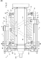
FIG. 2 is a schematic longitudinal sectional view of the conveying apparatus taken along theline 4b-4b ofFIG. 4 . -
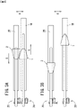
FIGS. 3A and 3B are schematic plan views showing a pad and a holding base. -
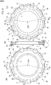
FIGS. 4(a), (b), and (c) are schematic front view, sectional view, and rear view, respectively, of a guide mechanism. -
FIG. 5(a) is a front view of a variable speed mechanism,FIGS. 5(b) and (c) are longitudinal sectional views showing second and first sliders, respectively, andFIG. 5(d) is a front view showing a part of theguide mechanism 30. -
FIG. 6 is a schematic perspective view of a conveying apparatus showing another embodiment of the present invention. -
FIG. 7 is a schematic perspective view showing a rail and a slider. - In the preferred conveying apparatus of the first aspect, the first and
second rails ring 3. - In this case, there is no need to provide a supporting ring for each rail.
- More preferably, the supporting
ring 3 includes a first surface IF which is one-side surface in the axial direction S and asecond surface 2F which is the other-side surface in the axial direction S, and thefirst rail 1L and thesecond rail 2L are attached to the first surface IF and thesecond surface 2F, respectively. - In this case, a guide mechanism including a supporting ring, a rail, and a slider is likely to be compact.
- Preferably, the
first rail 1L and thesecond rail 2L are each formed in a shape of an endless loop. - In this case, the prevision of each rail is high.
- Preferably, a pair of the
first rails 1L is provided in such a way that thefirst rails 1L are separated from each other in the axial direction S and a pair of thesecond rails 2L is provided in such a way that thesecond rails 2L are separated from each other in the axial direction S, the first sliders IS are provided for each rail of thefirst rails 1L, and thesecond sliders 2S are provided for each rail of thesecond rails 2L. - In this case, it is possible to support the pad by a pair of rails separated from each other in the axial direction S and the pad is not supported in a cantilever manner, which results in high durability and stability.
- Preferably, the conveying apparatus further includes a
tubular portion 31 that rotatably supports the rotating shaft, and the supportingring 3 is rotatably supported on thetubular portion 31. - In this case, the supporting
ring 3 rotates with the pads at high speeds and each slider reciprocates in response to variations in speed. This makes each slider and each rail less likely to be worn away and increases durability thereof. - In the preferred conveying method, a step in which the
first pads 1 and thesecond pads 2 receive the workpieces W from an upstream apparatus and thefirst pads 1 and thesecond pads 2 deliver the workpieces W to a downstream apparatus in the moving and separating step. - In this case, it is possible to perform what is called a repitch operation that increases the distance between two workpieces which are close to each other.
- In the preferred conveying apparatus of the second aspect, for each of the
first pads 1, the number of the first sliders IS is larger than the number of thesecond sliders 2S, and, for each of thesecond pads 2, the number of the first sliders IS is smaller than the number of thesecond sliders 2S. - In this case, after making the shapes and sizes of the first and second sliders uniform, it is possible to set the first and second sliders so as to have the aforementioned contact length relationship only by a difference in the number of first or second sliders supporting each pad.
- For example, each of the
first pads 1 may be supported by two first sliders IS and onesecond slider 2S and each of thesecond pads 2 may be supported by one first slider IS and twosecond sliders 2S. - More preferably, a first length L1 of each of the
first pads 1 in the circumferential direction R is shorter than the first contact length L11 and longer than the second contact length L12, and a second length L2 of each of thesecond pads 2 in the circumferential direction R is longer than the third contact length L21 and shorter than the fourth contact length L22. - In this case, a slider having a contact length longer than the length of each pad in the circumferential direction achieves stable orbiting of the pad.
- Any feature illustrated and/or depicted in conjunction with one of the aforementioned aspects or the following embodiments may be used in the same or similar form in one or more of the other aspects or other embodiments, and/or may be used in combination with, or in place of, any feature of the other aspects or embodiments.
- The present invention will be understood more clearly from the following description of preferred embodiments taken in conjunction with the accompanying drawings. Note however that the embodiments and the drawings are merely illustrative and should not be taken to define the scope of the present invention. The scope of the present invention shall be defined only by the appended claims. In the accompanying drawings, like reference numerals denote like components throughout the plurality of figures.
- Hereinafter, one embodiment of the present invention will be described in accordance with the drawings.
- First, an outline of the present manufacturing apparatus will be described.
- In
FIG. 1 , the present manufacturing apparatus includes an upstream roll (an upstream apparatus) 4, a variablespeed conveying apparatus 5, and a downstream roll (a downstream apparatus) 6. The variablespeed conveying apparatus 5 includes a plurality of first andsecond pads pads - The
pads speed conveying apparatus 5 with the speeds of thepads - Next, the details of a
variable speed mechanism 20 of this embodiment will be described. Thevariable speed mechanism 20 is provided for each of thepads pads pads - As shown in
FIG. 1 , a plurality of crankarms 22 are arranged on onedriving wheel 21 with an equiangular pitch. The space between thecrank arms 22 is unchangeable, andarm centers 220, which are the rotation centers of these crankarms 22, rotate with thedriving wheel 21 at the same angular speed. Thedriving wheel 21 rotates with arotating shaft 10 in the circumferential direction R at a constant angular speed. - A
cam roller 223 for varying speed is provided in a position separated from thearm center 220 of each crankarm 22, and thecam roller 223 moves along acam groove 44 for varying speed ofFIG. 2 . Thecam groove 44 for varying speed is eccentric with respect to a center ofdrive 210, which is the rotation center of thedriving wheel 21, and is immovable. Thus, the distance from the center ofdrive 210 to thecam roller 223 periodically increases and reduces depending on the positions of thecam roller 223 and thecam groove 44. - Consequently, each crank
arm 22 ofFIG. 1 periodically swings within a given angular range and the tip of thecrank arm 22 periodically swings. That is, in the approximately left half of an area shown inFIG. 1 , the tip of each crankarm 22 is displaced from thearm center 220 of thecrank arm 22 in a conveyance direction along the circumferential direction R; in the approximately right half of the area shown inFIG. 1 , the tip of each crankarm 22 is displaced in an opposite direction. - A
link lever 23 pin linked to the tip of each crankarm 22 and each of the first andsecond pads crank arm 22. Due to the above-mentioned swing of each crankarm 22, the distance between thearm center 220 of thecrank arm 22 and each of thepads first pad 1 and thesecond pad 2 that are adjacent to each other also varies. Consequently, the angular speeds of the first andsecond pads pads - Next, a
guide mechanism 30 guiding the above-mentioned orbiting of thepads - As shown in
FIG. 2 , the first andsecond pads guide mechanism 30 along the above-mentioned orbit via first andsecond bases guide mechanism 30 includes first and second sliders IS and 2S, first andsecond rails ring 3 in the shape of a doughnut-shaped plate, which are shown inFIGS. 2 and4 . - In
FIG. 2 , thedriving wheel 21 integrally rotates with the rotatingshaft 10. The rotatingshaft 10 is rotatably supported on the inner circumferential side of atubular portion 31. On the other hand, the supportingring 3 is rotatably supported on the outer periphery of thetubular portion 31. A driving force of an unillustrated motor may be input to the supportingring 3 to make the supportingring 3 rotate at a constant angular speed. - In
FIGS. 5(b) and (c) , thefirst rail 1L and thesecond rail 2L are attached to a first surface IF which is one surface of each supportingring 3 in the axial direction S and asecond surface 2F which is the other surface in the axial direction S, respectively. Consequently, thefirst rail 1L and thesecond rail 2L are provided so as to be separated from each other in the axial direction S and parallel to each other. Moreover, a pair offirst rails 1L is arranged such that thefirst rails 1L are parallel to each other, and a pair ofsecond rails 2L is also arranged such that thesecond rails 2L are parallel to each other. - As shown in
FIGS. 4(a) and (c) , each of therails first rail 1L ofFIG. 4(b) . On the other hand, only thesecond slider 2S is slidably attached to thesecond rail 2L. - In
FIG. 2 , thesliders rails drive 210 than thepads sliders pads - In
FIG. 5 , the first sliders IS are provided for the respectivefirst pads 1 in different positions from thesecond sliders 2S in the axial direction S of the rotating shaft 10 (FIG. 2 ) and orbit with thefirst pads 1 with the speeds of the first sliders IS and the first pads being varied. Thesecond sliders 2S are provided for the respectivesecond pads 2 in different positions from the first sliders IS in the axial direction S of the rotating shaft 10 (FIG. 2 ) and orbit with thesecond pads 2 with the speeds of thesecond sliders 2S and the second pads being varied. The above-mentionedfirst rail 1L ofFIG. 2 supports thefirst pads 1 via the first sliders IS and thefirst bases 1B, and guides the first sliders IS and does not guide thesecond sliders 2S. On the other hand, thesecond rail 2L supports thesecond pads 2 via thesecond sliders 2S and thesecond bases 2B, and guides thesecond sliders 2S and does not guide the first sliders IS. - In the present embodiment, each rail is formed so as to be convex in cross section and each slider is formed so as to be concave in cross section. However, each rail may be formed as a concave groove and each slider may be formed so as to be convex.
- In
FIG. 2 , acam drum 32 may be fixed to thetubular portion 31. First andsecond cam grooves pads cam drum 32. - In
FIG. 2 , the first andsecond pads second bases second pads second pads second cam followers second cam grooves - Consequently, the above-mentioned first and
second pads FIG. 3A separate from each other in the circumferential direction R and also separate from each other in the axial direction S as shown inFIG. 3B while rotating in the circumferential direction R (FIG. 1 ). - As shown in
FIG. 3A , thepads first base 1B and thesecond base 2B ofFIG. 3A approach each other in the reception position P1 ofFIG. 1 , that is, at low speeds. - On the other hand, in the reception position P1, the first and
second sliders FIGS. 4(a) and (c) are relatively displaced to the extent that a part of the first slider IS and a part of thesecond slider 2S overlap each other in the circumferential direction R. This makes it possible to increase the length (size) of each of thesliders pads FIG. 1 and thereby increase the number ofpads - This makes high-speed conveyance of small workpieces possible.
- Next, a method of variable speed conveyance of the workpieces W of
FIG. 1 will be described. - Variable speed conveyance of the workpieces includes the following steps: a conveying step, an accelerating step, a moving and separating step, a decelerating step, and a moving and approaching step.
- The first and
second pads FIG. 1 receive the workpieces W from the upstream roll 4 in the reception position P1 by sucking the workpieces W and making them cling thereto by negative pressure. The first andsecond pads second pads second pads FIG. 1 return to the reception position P1 with the speeds thereof being varied. The following are detailed descriptions of these operations. - In the above-mentioned accelerating stroke (period), the circumferential velocities of the first and
second pads variable speed mechanisms 20. As a result, the speeds of thepads second pads - It is to be noted that the operation and structure of the
variable speed mechanism 20 are well known per se and disclosed in, for example,WO 2018/011905 , the contents of which are incorporated herein in their entirety. - That is, in the moving and separating step, the first and
second pads first pad 1 and thesecond pad 2, whose speeds were increased by acceleration, is increased. - On the other hand, the first and
second pads FIGS. 3A and 3B by being guided by the first andsecond cam grooves cam drum 32 as shown inFIG. 2 , and then the distance between the first andsecond pads - Then, the first and
second pads FIG. 1 arrive at the delivery position P2 abutting on the downstream roll 6 and deliver the workpieces W held thereby to the downstream roll 6. At the time of this delivery, the circumferential velocities of thepads pads pads pads - When the workpieces W are delivered in a state in which they are separated in both the circumferential direction R and the axial direction S of
FIG. 3 as described above, the workpiece W may be a panel placed in a main body portion of a disposable diaper. A method for placing such a panel is disclosed inWO 2017/056952 A1 , for example. - After the above-mentioned delivery, the circumferential velocities of the first and
second pads FIG. 1 are decelerated by thevariable speed mechanisms 20 from the delivery position P2 until arrival at the reception position P1; in this way, the decelerating step is performed. During this deceleration, the first andsecond pads second cam grooves FIG. 2 and approach each other in the circumferential direction R as shown inFIG. 3A . - When arriving at the reception position P1 in a state in which the first and
second pads FIG. 1 approach each other in the circumferential direction R, the first andsecond pads - In this case, when the workpiece W is small, the
pads FIG. 3A are also small in the circumferential direction R and thepads pads guide mechanism 30 ofFIG. 4 . - The first and
second sliders guide mechanism 30 ofFIG. 4 need a certain length in the circumferential direction R in order to stabilize guidance of the pads in the circumferential direction R. Thus, in the reception position P1, theadjacent sliders - That is, a step is performed in which, in the reception position P1 of
FIG. 4 , the first slider IS and thesecond slider 2S after deceleration overlap each other in a part in the circumferential direction R, which causes thefirst pad 1 and thesecond pad 2 ofFIG. 5 to approach each other, and thefirst pad 1 and thesecond pad 2 move in this state in which they have approached each other. During this step, thefirst pad 1 and thesecond pad 2 receive the workpieces W from the upstream roll 4 in the reception position P1. - The reason why this overlapping is made possible is that, in
FIG. 5 , the first slider IS ofFIG. 5(c) guiding thefirst pad 1 in the circumferential direction R slides on thefirst rail 1L and thesecond slider 2S ofFIG. 5(b) guiding thesecond pad 2 ofFIG. 5(a) in the circumferential direction R slides on thesecond rail 2L. That is, the reason is that, since the first slider IS and thesecond slider 2S, which are adjacent to each other, ofFIG. 5(d) slide on the first andsecond rails FIGS. 5(b) and (c) , they can approach each other in an overlapping state as shown inFIG. 5(d) . - Incidentally, in the present invention, there is no need for the
pads FIGS. 3A and 3B . Moreover, thepads WO 2005/075163 , the contents of which are incorporated herein in their entirety. - Moreover, the
rails FIGS. 5(b) and (c) may be arranged side by side on the outer circumferential surface of the supportingring 3, not on the first surface IF or thesecond surface 2F of the supportingring 3. - Furthermore, the pads of the aforementioned embodiment are roughly triangular or pentagonal in shape; they may be square or rectangular in shape.
- In addition, the first pad and the second pad may be completely identical in shape.
- Moreover, each pad may include, for example, a machining apparatus such as an anvil. Furthermore, each pad may hold the workpiece by sucking the workpiece and making it cling thereto by negative pressure or may hold the workpiece by a needle, a hook, or the like.
- Next, another embodiment of the variable
speed conveying apparatus 5 will be described. -
FIGS. 6 and7 show the variablespeed conveying apparatus 5 and theguide mechanism 30, respectively, of the other embodiment. - In
FIG. 6 , the variablespeed conveying apparatus 5 includes a large number of first andsecond pads second rails - The first and
second pads axis 10S, orbit along an orbit with the speeds thereof being varied, are alternately arranged so as to be adjacent to each other in a circumferential direction R, and convey workpieces while holding them. Also in the present embodiment, as in the case of the aforementioned embodiment, thepads speed conveying apparatus 5 with the speeds of thepads - It is to be noted that, also in the present embodiment, the workpiece may be held by being sucked and made to cling to the outer surface of the pad.
- Next, the details of the
guide mechanism 30 will be described. - The first and
second sliders second pads axis 10S and orbit with the first andsecond pads second sliders - It is to be noted that, as in the case of the aforementioned embodiment, the
axis 10S is the axis of the rotating shaft 10 (seeFIG. 2 ). - The
first rail 1L supports thefirst pads 1 or thesecond pads 2 via thefirst sliders 1S, and guides the first sliders IS and does not guide thesecond sliders 2S. On the other hand, thesecond rail 2L supports thefirst pads 1 or thesecond pads 2 via thesecond sliders 2S, and guides thesecond sliders 2S and does not guide the first sliders IS. - As is clearly shown in
FIG. 7 , the above-mentionedsecond rail 2L is arranged so as to be separated from the above-mentionedfirst rail 1L and parallel thereto. It is to be noted that, as in the case of the above-mentioned embodiment, therails - Also in the present embodiment of
FIG. 6 , as in the case of the aforementioned embodiment, thesliders rails axis 10S than thepads sliders pads - As shown in
FIG. 6 , eachfirst pad 1 is supported by two first sliders IS and onesecond slider 2S. On the other hand, eachsecond pad 2 is supported by one first slider IS and twosecond sliders 2S. - It is to be noted that the
sliders - As described above, the number of sliders supporting each of the
pads first pad 1, a first contact length L11 by which the first sliders IS are in contact with thefirst rail 1L is longer than a second contact length L12 by which thesecond slider 2S is in contact with thesecond rail 2L. Moreover, for eachsecond pad 2, a third contact length L21 by which the first slider IS is in contact with thefirst rail 1L is shorter than a fourth contact length L22 by which thesecond sliders 2S are in contact with thesecond rail 2L. - In
FIG. 6 , a first length L1 of eachfirst pad 1 mentioned above in the above-mentioned circumferential direction R is shorter than the first contact length L11 and longer than the second contact length L12. - On the other hand, a second length L2 of each
second pad 2 in the circumferential direction R is longer than the third contact length L21 and shorter than the fourth contact length L22. - Since the contact lengths L1 to L4 of the
sliders pads first pad 1 andsecond pad 2 approach each other. - On the other hand, it is possible to support the
first pad 1 with two first sliders IS and onesecond slider 2S, which stabilizes support in the circumferential direction. Moreover, support of thesecond pad 2 in the circumferential direction is also stabilized in a similar manner. - It is to be noted that two first sliders IS supporting the
first pad 1 may be provided as one first slider IS which is long in the circumferential direction R. Likewise, twosecond sliders 2S supporting thesecond pad 2 may be provided as onesecond slider 2S which is long in the circumferential direction R. - Next, a method of variable speed conveyance of the workpieces will be described.
- Variable speed conveyance of the workpieces includes the following steps: a conveying step, an accelerating step, a moving and separating step, a decelerating step, and a moving and approaching step.
- The first and
second pads FIG. 6 receive the workpieces from the upstream roll in the reception position P1 by sucking the workpieces and making them cling thereto by negative pressure. The first andsecond pads second pads second pads - In the above-mentioned accelerating stroke (period), the circumferential velocities of the first and
second pads variable speed mechanisms 20. As a result, the speeds of thepads second pads - It is to be noted that the operation and structure of the
variable speed mechanism 20 are well known per se and disclosed in, for example,WO 2018/011905 , the contents of which are incorporated herein in their entirety. - Then, the first and
second pads pads pads pads pads - After the above-mentioned delivery, the circumferential velocities of the first and
second pads second pads - When arriving at the reception position P1 in a state in which the first and
second pads second pads - A step is performed in which, in the reception position P1 of
FIG. 7 , the first slider IS and thesecond slider 2S after deceleration overlap each other in a part Δ in the circumferential direction R, which causes thefirst pad 1 and thesecond pad 2 ofFIG. 6 to approach each other, and thefirst pad 1 and thesecond pad 2 move in this state in which they have approached each other. During this step, thefirst pad 1 and thesecond pad 2 receive the workpieces from the upstream roll in the reception position P1. - The reason why this overlapping is made possible is that, in
FIG. 6 , the first slider IS guiding thefirst pad 1 in the circumferential direction R slides on thefirst rail 1L and thesecond slider 2S guiding thesecond pad 2 in the circumferential direction R slides on thesecond rail 2L. That is, the reason is that, since the first slider IS and thesecond slider 2S ofFIG. 7 that move in parallel to each other slide on the first andsecond rails axis 10S, the first slider IS and thesecond slider 2S can approach each other in a state in which they overlap each other in the circumferential direction R. - While the preferred embodiments have been described above with reference to the drawings, a person skilled in the art would easily conceive of various changes and modifications based on the description within the scope obvious to the person skilled in the art.
- For example, there is no need for the supporting ring to rotate in synchronization with the rotating shaft. Moreover, a supporting member which is not continuous in a circular fashion may be adopted in place of the supporting ring.
- The speed of each pad may be constant in the reception position from the start to end of reception.
- The upstream apparatus and the downstream apparatus may be conveyors and the like, not rolls.
- Therefore, these changes and modifications are construed as being included in the scope of the present invention defined by the claims.
- In addition to finished articles of various absorbent articles such as disposable pants and diapers, the present invention can be used in conveyance in the manufacture of parts and half-finished articles of these absorbent articles.
-
- 1:
- first pad
- 2:
- second pad
- 1B:
- first base
- 2B:
- second base
- 1C:
- first cam follower
- 2C:
- second cam follower
- 1S:
- first slider
- 2S:
- second slider
- 1L:
- first rail
- 2L:
- second rail
- 1F:
- first surface
- 2F:
- second surface
- 10:
- rotating shaft
- 10S:
- axis
- 20:
- variable speed mechanism
- 21:
- driving wheel
- 210:
- center of drive
- 22:
- crank arm
- 220:
- arm center
- 223:
- cam roller
- 23:
- link lever
- 3:
- supporting ring
- 30:
- guide mechanism
- 31:
- tubular portion
- 32:
- cam drum
- 4:
- upstream roll (apparatus)
- 5:
- variable speed conveying apparatus
- 6:
- downstream roll (apparatus)
- 41:
- first cam groove
- 42:
- second cam groove
- 44:
- cam groove for varying speed
- P1:
- reception position
- P2:
- delivery position
- R:
- circumferential direction
- S:
- axial direction
- W:
- workpiece
- L1:
- first length
- L2:
- second length
- L11, L12, L21, L22:
- first to fourth contact lengths
Claims (13)
- A conveying apparatus comprising:a rotating shaft 10;first pads 1 and second pads 2 arranged around the rotating shaft 10, the first and second pads orbiting along an orbit with their speeds being varied, the first and second pads being alternately arranged so as to be adjacent to each other in a circumferential direction R and each holding a workpiece W;a variable speed mechanism 20 provided for each of the first and second pads, the variable speed mechanism 20 for accelerating and decelerating each of the first and second pads during the orbiting;a first slider IS provided for each of the first pads 1 in a different position in an axial direction S of the rotating shaft, the first slider IS orbiting with the corresponding first pad 1 with speeds of the first slider IS and the corresponding first pad 1 being varied;a second slider 2S provided for each of the second pads 2 in a different position in the axial direction S of the rotating shaft, the second slider 2S orbiting with the corresponding second pad 2 with speeds of the second slider 2S and the corresponding second pad 2 being varied;a first rail 1L supporting the first pads 1 via the first sliders 1S, the first rail 1L guiding the first sliders IS and not guiding the second sliders 2S; anda second rail 2L arranged so as to be spaced apart from the first rail 1L and supporting the second pads 2 via the second sliders 2S, the second rail 2L guiding the second sliders 2S and not guiding the first sliders IS.
- The conveying apparatus according to claim 1,
wherein the first rail 1L and the second rail 2L are attached to one supporting ring 3. - The conveying apparatus according to claim 2,wherein the one supporting ring 3 comprises a first surface IF which is one-side surface in the axial direction S and a second surface 2F which is another-side surface in the axial direction S, andwherein the first rail 1L is attached to the first surface IF and the second rail 2L is attached to the second surface 2F.
- The conveying apparatus according to claim 2,
wherein the first rail 1L and the second rail 2L are each formed in a shape of an endless loop. - The conveying apparatus according to any one of claims 1 to 4,wherein a pair of the first rails 1L is provided in such a way that the first rails 1L are separated from each other in the axial direction S and a pair of the second rails 2L is provided in such a way that the second rails 2L are separated from each other in the axial direction S,wherein the first sliders IS are provided for the respective first rails 1L, andwherein the second sliders 2S are provided for the respective second rails 2L.
- The conveying apparatus according to claim 2, further comprising:a tubular portion 31 that rotatably supports the rotating shaft,wherein the supporting ring 3 is rotatably supported on the tubular portion 31.
- A method for conveying the workpieces W using the conveying apparatus according to claim 1, comprising:a step of conveying in which the first and second pads 1 and 2 convey the workpieces W with speeds of the first and second pads 1 and 2 being varied;a step of accelerating in which circumferential velocities of the first and second pads 1 and 2 are accelerated by the respective variable speed mechanisms 20;a step of moving and separating in which the first and second pads 1 and 2 move in a state where a distance between the first pad 1 and the second pad 2 is increased and the first pad and the second pad are separated with each other after speeds of the first and second pads increased in the step of accelerating;a step of decelerating in which the circumferential velocities of the first and second pads 1 and 2 are decelerated by the respective variable speed mechanisms 20; anda step of moving and approaching in which the first slider IS and the second slider 2S, which have been decelerated in the step of decelerating, overlap each other in a part in the circumferential direction R, which causes the first pad 1 and the second pad 2 to approach each other, and the first pad 1 and the second pad 2 move in this state where the first pad 1 and the second pad 2 have approached each other.
- The conveying method according to claim 7, comprising:a receiving step in which the first pads 1 and the second pads 2 receive the workpieces W from an upstream apparatus 4 in the step of moving and approaching; anda delivering step in which the first pads 1 and the second pads 2 deliver the workpieces W to a downstream apparatus 6 in the step of moving and separating.
- A conveying apparatus comprising:first pads 1 and second pads 2 arranged around an axis 10S, the first and second pads orbiting along an orbit with their speeds being varied, the first and second pads being alternately arranged so as to be adjacent to each other in a circumferential direction R and each holding a workpiece W;a first slider IS and a second slider 2S provided for each of the first and second pads 1 and 2 in different positions with each other in an axial direction S of the axis 10S, the first and second sliders orbiting with the first and second pads 1 and 2 with speeds of the first and second sliders 1S and 2S and the first and second pads being varied;a first rail 1L supporting the first pads 1 or the second pads 2 via the first sliders 1S, the first rail 1L guiding the first sliders IS and not guiding the second sliders 2S; anda second rail 2L arranged so as to be spaced apart from the first rail 1L, the second rail supporting the first pads 1 or the second pads 2 via the second sliders 2S, the second rail guiding the second sliders 2S and not guiding the first sliders 1S,wherein, for each of the first pads 1, a first contact length L11 by which the first slider IS is in contact with the first rail 1L is longer than a second contact length L12 by which the second slider 2S is in contact with the second rail 2L, andwherein, for each of the second pads 2, a third contact length L21 by which the first slider IS is in contact with the first rail 1L is shorter than a fourth contact length L22 by which the second slider 2S is in contact with the second rail 2L.
- The conveying apparatus according to claim 9,wherein, for each of the first pads 1, the number of the first sliders IS is larger than the number of the second sliders 2S, andwherein, for each of the second pads 2, the number of the first sliders IS is smaller than the number of the second sliders 2S.
- The conveying apparatus according to claim 10,wherein each of the first pads 1 is supported by two of the first sliders IS and one of the second slider 2S, andwherein each of the second pads 2 is supported by one of the first slider IS and two of the second sliders 2S.
- The conveying apparatus according to claim 9,wherein a first length L1 of each of the first pads 1 in the circumferential direction R is shorter than the first contact length L11 and longer than the second contact length L12, andwherein a second length L2 of each of the second pads 2 in the circumferential direction R is longer than the third contact length L21 and shorter than the fourth contact length L22.
- A method for conveying the workpieces W using the conveying apparatus according to claim 9, comprising:a step in which the first and second pads 1 and 2 convey the workpieces W with speeds of the first and second pads 1 and 2 being varied;a step of accelerating in which circumferential velocities of the first and second pads 1 and 2 are accelerated;a step in which the first and second pads 1 and 2 move in a state where a distance between the first pad 1 and the second pad 2 is increased and the first pad and the second pad are separated with each other after speeds of the first and second pads increased in the step of accelerating;a step of decelerating in which the circumferential velocities of the first and second pads 1 and 2 are decelerated; anda step in which the first slider IS and the second slider 2S, which have been decelerated in the step of decelerating, overlap each other in a part in the circumferential direction R, which causes the first pad 1 and the second pad 2 to approach each other, and the first pad 1 and the second pad 2 move in this state where the first pad 1 and the second pad 2 have approached each other.
Applications Claiming Priority (2)
| Application Number | Priority Date | Filing Date | Title |
|---|---|---|---|
| JP2019108546 | 2019-06-11 | ||
| PCT/JP2020/021290 WO2020250710A1 (en) | 2019-06-11 | 2020-05-29 | Conveyance device and method |
Publications (2)
| Publication Number | Publication Date |
|---|---|
| EP3984924A1 true EP3984924A1 (en) | 2022-04-20 |
| EP3984924A4 EP3984924A4 (en) | 2022-08-10 |
Family
ID=73782001
Family Applications (1)
| Application Number | Title | Priority Date | Filing Date |
|---|---|---|---|
| EP20823230.6A Withdrawn EP3984924A4 (en) | 2019-06-11 | 2020-05-29 | DEVICE AND METHOD OF TRANSPORT |
Country Status (4)
| Country | Link |
|---|---|
| US (1) | US11708224B2 (en) |
| EP (1) | EP3984924A4 (en) |
| JP (1) | JP7277583B2 (en) |
| WO (1) | WO2020250710A1 (en) |
Families Citing this family (2)
| Publication number | Priority date | Publication date | Assignee | Title |
|---|---|---|---|---|
| JP7110467B1 (en) * | 2021-07-30 | 2022-08-01 | 株式会社瑞光 | Conveyor |
| CN120397720B (en) * | 2025-05-07 | 2025-11-04 | 苏州天成涂装系统股份有限公司 | Electrophoresis rotary dip-coating conveying device for pretreatment of vehicle body |
Family Cites Families (15)
| Publication number | Priority date | Publication date | Assignee | Title |
|---|---|---|---|---|
| US1245513A (en) * | 1916-09-14 | 1917-11-06 | James Edward Rogers | Vehicle-wheel. |
| GB1120903A (en) * | 1965-09-17 | 1968-07-24 | Jagenberg Werke Ag | Apparatus for labelling bottles or other articles |
| US3963557A (en) * | 1974-05-28 | 1976-06-15 | Minnesota Mining And Manufacturing Company | Article transferring apparatus |
| NL174031C (en) * | 1978-09-14 | 1984-04-16 | Tevopharm Schiedam Bv | Apparatus for the conveying between objects of a towed conveyor of objects which are conveyed continuously in a continuous row. |
| US6371254B1 (en) * | 1995-10-06 | 2002-04-16 | John W. Koshak | Jack arrestor |
| US6730189B1 (en) * | 1999-06-25 | 2004-05-04 | The Procter & Gamble Company | Process for manufacturing disposable absorbent articles, and an apparatus for performing the process |
| JP4617592B2 (en) * | 2001-03-30 | 2011-01-26 | 澁谷工業株式会社 | Resin container transfer system |
| US6511065B1 (en) * | 2001-08-28 | 2003-01-28 | Heidelberger Druckmaschinen Ag | Method for transferring signatures and gripper assembly for a matched velocity transfer device |
| US20040245069A1 (en) * | 2004-01-21 | 2004-12-09 | The Procter & Gamble Company | Method of variable pitch-spacing and turning of work pieces |
| EP1726414B1 (en) | 2004-02-05 | 2013-03-27 | Zuiko Corporation | Web processing device |
| ITBO20070431A1 (en) * | 2007-06-19 | 2008-12-20 | Gdm Spa | MACHINE AND METHOD FOR THE CONSTRUCTION OF ABSORBENT ITEMS. |
| ITBO20120655A1 (en) * | 2012-12-03 | 2014-06-04 | Gdm Spa | MACHINE FOR THE CONSTRUCTION OF HYGIENIC ABSORBENT ITEMS. |
| US10206822B2 (en) * | 2015-09-29 | 2019-02-19 | Zuiko Corporation | Method and device for manufacturing disposable worn article |
| US10905597B2 (en) | 2016-07-13 | 2021-02-02 | Zuiko Corporation | Conveying device and method for manufacturing disposable wearable article using same |
| IT201600087583A1 (en) * | 2016-08-26 | 2018-02-26 | Gdm Spa | Equipment for transferring and rotating an object |
-
2020
- 2020-05-29 JP JP2021525993A patent/JP7277583B2/en active Active
- 2020-05-29 EP EP20823230.6A patent/EP3984924A4/en not_active Withdrawn
- 2020-05-29 US US17/614,012 patent/US11708224B2/en active Active
- 2020-05-29 WO PCT/JP2020/021290 patent/WO2020250710A1/en not_active Ceased
Also Published As
| Publication number | Publication date |
|---|---|
| BR112021023915A2 (en) | 2022-01-04 |
| JPWO2020250710A1 (en) | 2020-12-17 |
| JP7277583B2 (en) | 2023-05-19 |
| US11708224B2 (en) | 2023-07-25 |
| WO2020250710A1 (en) | 2020-12-17 |
| EP3984924A4 (en) | 2022-08-10 |
| US20220219913A1 (en) | 2022-07-14 |
Similar Documents
| Publication | Publication Date | Title |
|---|---|---|
| EP2486903B1 (en) | Single transfer insert placement method and apparatus | |
| JP6888080B2 (en) | A device for transferring and rotating an object | |
| RU2437640C1 (en) | Nappy/diaper blanks folder and method of folding | |
| US11708224B2 (en) | Conveying apparatus and method | |
| US10039674B2 (en) | Conveyance device | |
| JPWO2001044086A1 (en) | Conveying method and conveying device | |
| US12029630B2 (en) | Apparatus and method for manufacturing absorbent article | |
| JP7166279B2 (en) | Absorbent article manufacturing apparatus and manufacturing method | |
| EP2659869A1 (en) | Single transfer insert placement method and apparatus with cross-direction insert placement control | |
| EP3741337B1 (en) | Manufacturing method and manufacturing device of disposable wearable article | |
| EP2659868A1 (en) | Single transfer insert placement method and apparatus | |
| JPS60157418A (en) | Device for shifting direction of carrying of cylindrical product in lateral direction from longitudinal direction | |
| JP6058659B2 (en) | Conveying apparatus and object conveying method | |
| BR112021023915B1 (en) | APPARATUS AND METHOD OF TRANSPORT | |
| CN115103808B (en) | Sheet-like article conveying device and disposable wearing article manufacturing system equipped with the conveying device | |
| WO2017215643A1 (en) | Variable-pitch conveying apparatus for use in sanitary product manufacturing equipment | |
| EP1714878B1 (en) | Overwrapping machine for packets of cigarettes | |
| CN117396164A (en) | Manufacturing method and manufacturing device of wearing articles | |
| JPH10314873A (en) | Reversing device |
Legal Events
| Date | Code | Title | Description |
|---|---|---|---|
| STAA | Information on the status of an ep patent application or granted ep patent |
Free format text: STATUS: THE INTERNATIONAL PUBLICATION HAS BEEN MADE |
|
| PUAI | Public reference made under article 153(3) epc to a published international application that has entered the european phase |
Free format text: ORIGINAL CODE: 0009012 |
|
| STAA | Information on the status of an ep patent application or granted ep patent |
Free format text: STATUS: REQUEST FOR EXAMINATION WAS MADE |
|
| 17P | Request for examination filed |
Effective date: 20211130 |
|
| AK | Designated contracting states |
Kind code of ref document: A1 Designated state(s): AL AT BE BG CH CY CZ DE DK EE ES FI FR GB GR HR HU IE IS IT LI LT LU LV MC MK MT NL NO PL PT RO RS SE SI SK SM TR |
|
| A4 | Supplementary search report drawn up and despatched |
Effective date: 20220708 |
|
| RIC1 | Information provided on ipc code assigned before grant |
Ipc: B65G 47/28 20060101ALI20220704BHEP Ipc: B65G 47/26 20060101ALI20220704BHEP Ipc: B65G 47/84 20060101ALI20220704BHEP Ipc: A61F 13/15 20060101ALI20220704BHEP Ipc: B65G 47/86 20060101AFI20220704BHEP |
|
| DAV | Request for validation of the european patent (deleted) | ||
| DAX | Request for extension of the european patent (deleted) | ||
| STAA | Information on the status of an ep patent application or granted ep patent |
Free format text: STATUS: EXAMINATION IS IN PROGRESS |
|
| 17Q | First examination report despatched |
Effective date: 20231220 |
|
| STAA | Information on the status of an ep patent application or granted ep patent |
Free format text: STATUS: THE APPLICATION IS DEEMED TO BE WITHDRAWN |
|
| 18D | Application deemed to be withdrawn |
Effective date: 20250611 |