EP3984823B1 - Side camera for vehicle and method of controlling the same - Google Patents
Side camera for vehicle and method of controlling the same Download PDFInfo
- Publication number
- EP3984823B1 EP3984823B1 EP21200640.7A EP21200640A EP3984823B1 EP 3984823 B1 EP3984823 B1 EP 3984823B1 EP 21200640 A EP21200640 A EP 21200640A EP 3984823 B1 EP3984823 B1 EP 3984823B1
- Authority
- EP
- European Patent Office
- Prior art keywords
- blind
- vehicle
- camera
- spot view
- spot
- Prior art date
- Legal status (The legal status is an assumption and is not a legal conclusion. Google has not performed a legal analysis and makes no representation as to the accuracy of the status listed.)
- Active
Links
Images


Classifications
-
- B—PERFORMING OPERATIONS; TRANSPORTING
- B60—VEHICLES IN GENERAL
- B60K—ARRANGEMENT OR MOUNTING OF PROPULSION UNITS OR OF TRANSMISSIONS IN VEHICLES; ARRANGEMENT OR MOUNTING OF PLURAL DIVERSE PRIME-MOVERS IN VEHICLES; AUXILIARY DRIVES FOR VEHICLES; INSTRUMENTATION OR DASHBOARDS FOR VEHICLES; ARRANGEMENTS IN CONNECTION WITH COOLING, AIR INTAKE, GAS EXHAUST OR FUEL SUPPLY OF PROPULSION UNITS IN VEHICLES
- B60K35/00—Instruments specially adapted for vehicles; Arrangement of instruments in or on vehicles
- B60K35/10—Input arrangements, i.e. from user to vehicle, associated with vehicle functions or specially adapted therefor
-
- B—PERFORMING OPERATIONS; TRANSPORTING
- B60—VEHICLES IN GENERAL
- B60K—ARRANGEMENT OR MOUNTING OF PROPULSION UNITS OR OF TRANSMISSIONS IN VEHICLES; ARRANGEMENT OR MOUNTING OF PLURAL DIVERSE PRIME-MOVERS IN VEHICLES; AUXILIARY DRIVES FOR VEHICLES; INSTRUMENTATION OR DASHBOARDS FOR VEHICLES; ARRANGEMENTS IN CONNECTION WITH COOLING, AIR INTAKE, GAS EXHAUST OR FUEL SUPPLY OF PROPULSION UNITS IN VEHICLES
- B60K35/00—Instruments specially adapted for vehicles; Arrangement of instruments in or on vehicles
- B60K35/20—Output arrangements, i.e. from vehicle to user, associated with vehicle functions or specially adapted therefor
- B60K35/21—Output arrangements, i.e. from vehicle to user, associated with vehicle functions or specially adapted therefor using visual output, e.g. blinking lights or matrix displays
- B60K35/22—Display screens
-
- B—PERFORMING OPERATIONS; TRANSPORTING
- B60—VEHICLES IN GENERAL
- B60K—ARRANGEMENT OR MOUNTING OF PROPULSION UNITS OR OF TRANSMISSIONS IN VEHICLES; ARRANGEMENT OR MOUNTING OF PLURAL DIVERSE PRIME-MOVERS IN VEHICLES; AUXILIARY DRIVES FOR VEHICLES; INSTRUMENTATION OR DASHBOARDS FOR VEHICLES; ARRANGEMENTS IN CONNECTION WITH COOLING, AIR INTAKE, GAS EXHAUST OR FUEL SUPPLY OF PROPULSION UNITS IN VEHICLES
- B60K35/00—Instruments specially adapted for vehicles; Arrangement of instruments in or on vehicles
- B60K35/20—Output arrangements, i.e. from vehicle to user, associated with vehicle functions or specially adapted therefor
- B60K35/26—Output arrangements, i.e. from vehicle to user, associated with vehicle functions or specially adapted therefor using acoustic output
-
- B—PERFORMING OPERATIONS; TRANSPORTING
- B60—VEHICLES IN GENERAL
- B60K—ARRANGEMENT OR MOUNTING OF PROPULSION UNITS OR OF TRANSMISSIONS IN VEHICLES; ARRANGEMENT OR MOUNTING OF PLURAL DIVERSE PRIME-MOVERS IN VEHICLES; AUXILIARY DRIVES FOR VEHICLES; INSTRUMENTATION OR DASHBOARDS FOR VEHICLES; ARRANGEMENTS IN CONNECTION WITH COOLING, AIR INTAKE, GAS EXHAUST OR FUEL SUPPLY OF PROPULSION UNITS IN VEHICLES
- B60K35/00—Instruments specially adapted for vehicles; Arrangement of instruments in or on vehicles
- B60K35/20—Output arrangements, i.e. from vehicle to user, associated with vehicle functions or specially adapted therefor
- B60K35/28—Output arrangements, i.e. from vehicle to user, associated with vehicle functions or specially adapted therefor characterised by the type of the output information, e.g. video entertainment or vehicle dynamics information; characterised by the purpose of the output information, e.g. for attracting the attention of the driver
-
- B—PERFORMING OPERATIONS; TRANSPORTING
- B60—VEHICLES IN GENERAL
- B60R—VEHICLES, VEHICLE FITTINGS, OR VEHICLE PARTS, NOT OTHERWISE PROVIDED FOR
- B60R1/00—Optical viewing arrangements; Real-time viewing arrangements for drivers or passengers using optical image capturing systems, e.g. cameras or video systems specially adapted for use in or on vehicles
-
- B—PERFORMING OPERATIONS; TRANSPORTING
- B60—VEHICLES IN GENERAL
- B60R—VEHICLES, VEHICLE FITTINGS, OR VEHICLE PARTS, NOT OTHERWISE PROVIDED FOR
- B60R11/00—Arrangements for holding or mounting articles, not otherwise provided for
- B60R11/04—Mounting of cameras operative during drive; Arrangement of controls thereof relative to the vehicle
-
- B—PERFORMING OPERATIONS; TRANSPORTING
- B60—VEHICLES IN GENERAL
- B60R—VEHICLES, VEHICLE FITTINGS, OR VEHICLE PARTS, NOT OTHERWISE PROVIDED FOR
- B60R16/00—Electric or fluid circuits specially adapted for vehicles and not otherwise provided for; Arrangement of elements of electric or fluid circuits specially adapted for vehicles and not otherwise provided for
- B60R16/02—Electric or fluid circuits specially adapted for vehicles and not otherwise provided for; Arrangement of elements of electric or fluid circuits specially adapted for vehicles and not otherwise provided for electric constitutive elements
- B60R16/023—Electric or fluid circuits specially adapted for vehicles and not otherwise provided for; Arrangement of elements of electric or fluid circuits specially adapted for vehicles and not otherwise provided for electric constitutive elements for transmission of signals between vehicle parts or subsystems
- B60R16/0231—Circuits relating to the driving or the functioning of the vehicle
- B60R16/0232—Circuits relating to the driving or the functioning of the vehicle for measuring vehicle parameters and indicating critical, abnormal or dangerous conditions
-
- G—PHYSICS
- G07—CHECKING-DEVICES
- G07C—TIME OR ATTENDANCE REGISTERS; REGISTERING OR INDICATING THE WORKING OF MACHINES; GENERATING RANDOM NUMBERS; VOTING OR LOTTERY APPARATUS; ARRANGEMENTS, SYSTEMS OR APPARATUS FOR CHECKING NOT PROVIDED FOR ELSEWHERE
- G07C5/00—Registering or indicating the working of vehicles
- G07C5/08—Registering or indicating performance data other than driving, working, idle, or waiting time, with or without registering driving, working, idle or waiting time
- G07C5/0816—Indicating performance data, e.g. occurrence of a malfunction
- G07C5/0825—Indicating performance data, e.g. occurrence of a malfunction using optical means
-
- G—PHYSICS
- G07—CHECKING-DEVICES
- G07C—TIME OR ATTENDANCE REGISTERS; REGISTERING OR INDICATING THE WORKING OF MACHINES; GENERATING RANDOM NUMBERS; VOTING OR LOTTERY APPARATUS; ARRANGEMENTS, SYSTEMS OR APPARATUS FOR CHECKING NOT PROVIDED FOR ELSEWHERE
- G07C5/00—Registering or indicating the working of vehicles
- G07C5/08—Registering or indicating performance data other than driving, working, idle, or waiting time, with or without registering driving, working, idle or waiting time
- G07C5/0816—Indicating performance data, e.g. occurrence of a malfunction
- G07C5/0833—Indicating performance data, e.g. occurrence of a malfunction using audio means
-
- H—ELECTRICITY
- H04—ELECTRIC COMMUNICATION TECHNIQUE
- H04N—PICTORIAL COMMUNICATION, e.g. TELEVISION
- H04N17/00—Diagnosis, testing or measuring for television systems or their details
- H04N17/002—Diagnosis, testing or measuring for television systems or their details for television cameras
-
- H—ELECTRICITY
- H04—ELECTRIC COMMUNICATION TECHNIQUE
- H04N—PICTORIAL COMMUNICATION, e.g. TELEVISION
- H04N17/00—Diagnosis, testing or measuring for television systems or their details
- H04N17/04—Diagnosis, testing or measuring for television systems or their details for receivers
-
- H—ELECTRICITY
- H04—ELECTRIC COMMUNICATION TECHNIQUE
- H04N—PICTORIAL COMMUNICATION, e.g. TELEVISION
- H04N23/00—Cameras or camera modules comprising electronic image sensors; Control thereof
- H04N23/57—Mechanical or electrical details of cameras or camera modules specially adapted for being embedded in other devices
-
- H—ELECTRICITY
- H04—ELECTRIC COMMUNICATION TECHNIQUE
- H04N—PICTORIAL COMMUNICATION, e.g. TELEVISION
- H04N23/00—Cameras or camera modules comprising electronic image sensors; Control thereof
- H04N23/90—Arrangement of cameras or camera modules, e.g. multiple cameras in TV studios or sports stadiums
-
- H—ELECTRICITY
- H04—ELECTRIC COMMUNICATION TECHNIQUE
- H04N—PICTORIAL COMMUNICATION, e.g. TELEVISION
- H04N5/00—Details of television systems
- H04N5/222—Studio circuitry; Studio devices; Studio equipment
- H04N5/262—Studio circuits, e.g. for mixing, switching-over, change of character of image, other special effects ; Cameras specially adapted for the electronic generation of special effects
- H04N5/2628—Alteration of picture size, shape, position or orientation, e.g. zooming, rotation, rolling, perspective, translation
-
- H—ELECTRICITY
- H04—ELECTRIC COMMUNICATION TECHNIQUE
- H04N—PICTORIAL COMMUNICATION, e.g. TELEVISION
- H04N5/00—Details of television systems
- H04N5/222—Studio circuitry; Studio devices; Studio equipment
- H04N5/262—Studio circuits, e.g. for mixing, switching-over, change of character of image, other special effects ; Cameras specially adapted for the electronic generation of special effects
- H04N5/268—Signal distribution or switching
-
- H—ELECTRICITY
- H04—ELECTRIC COMMUNICATION TECHNIQUE
- H04N—PICTORIAL COMMUNICATION, e.g. TELEVISION
- H04N7/00—Television systems
- H04N7/18—Closed-circuit television [CCTV] systems, i.e. systems in which the video signal is not broadcast
- H04N7/181—Closed-circuit television [CCTV] systems, i.e. systems in which the video signal is not broadcast for receiving images from a plurality of remote sources
-
- B—PERFORMING OPERATIONS; TRANSPORTING
- B60—VEHICLES IN GENERAL
- B60K—ARRANGEMENT OR MOUNTING OF PROPULSION UNITS OR OF TRANSMISSIONS IN VEHICLES; ARRANGEMENT OR MOUNTING OF PLURAL DIVERSE PRIME-MOVERS IN VEHICLES; AUXILIARY DRIVES FOR VEHICLES; INSTRUMENTATION OR DASHBOARDS FOR VEHICLES; ARRANGEMENTS IN CONNECTION WITH COOLING, AIR INTAKE, GAS EXHAUST OR FUEL SUPPLY OF PROPULSION UNITS IN VEHICLES
- B60K2360/00—Indexing scheme associated with groups B60K35/00 or B60K37/00 relating to details of instruments or dashboards
- B60K2360/16—Type of output information
- B60K2360/166—Navigation
-
- B—PERFORMING OPERATIONS; TRANSPORTING
- B60—VEHICLES IN GENERAL
- B60K—ARRANGEMENT OR MOUNTING OF PROPULSION UNITS OR OF TRANSMISSIONS IN VEHICLES; ARRANGEMENT OR MOUNTING OF PLURAL DIVERSE PRIME-MOVERS IN VEHICLES; AUXILIARY DRIVES FOR VEHICLES; INSTRUMENTATION OR DASHBOARDS FOR VEHICLES; ARRANGEMENTS IN CONNECTION WITH COOLING, AIR INTAKE, GAS EXHAUST OR FUEL SUPPLY OF PROPULSION UNITS IN VEHICLES
- B60K2360/00—Indexing scheme associated with groups B60K35/00 or B60K37/00 relating to details of instruments or dashboards
- B60K2360/16—Type of output information
- B60K2360/178—Warnings
-
- B—PERFORMING OPERATIONS; TRANSPORTING
- B60—VEHICLES IN GENERAL
- B60K—ARRANGEMENT OR MOUNTING OF PROPULSION UNITS OR OF TRANSMISSIONS IN VEHICLES; ARRANGEMENT OR MOUNTING OF PLURAL DIVERSE PRIME-MOVERS IN VEHICLES; AUXILIARY DRIVES FOR VEHICLES; INSTRUMENTATION OR DASHBOARDS FOR VEHICLES; ARRANGEMENTS IN CONNECTION WITH COOLING, AIR INTAKE, GAS EXHAUST OR FUEL SUPPLY OF PROPULSION UNITS IN VEHICLES
- B60K2360/00—Indexing scheme associated with groups B60K35/00 or B60K37/00 relating to details of instruments or dashboards
- B60K2360/20—Optical features of instruments
- B60K2360/21—Optical features of instruments using cameras
-
- B—PERFORMING OPERATIONS; TRANSPORTING
- B60—VEHICLES IN GENERAL
- B60R—VEHICLES, VEHICLE FITTINGS, OR VEHICLE PARTS, NOT OTHERWISE PROVIDED FOR
- B60R2300/00—Details of viewing arrangements using cameras and displays, specially adapted for use in a vehicle
- B60R2300/10—Details of viewing arrangements using cameras and displays, specially adapted for use in a vehicle characterised by the type of camera system used
- B60R2300/101—Details of viewing arrangements using cameras and displays, specially adapted for use in a vehicle characterised by the type of camera system used using cameras with adjustable capturing direction
-
- B—PERFORMING OPERATIONS; TRANSPORTING
- B60—VEHICLES IN GENERAL
- B60R—VEHICLES, VEHICLE FITTINGS, OR VEHICLE PARTS, NOT OTHERWISE PROVIDED FOR
- B60R2300/00—Details of viewing arrangements using cameras and displays, specially adapted for use in a vehicle
- B60R2300/10—Details of viewing arrangements using cameras and displays, specially adapted for use in a vehicle characterised by the type of camera system used
- B60R2300/105—Details of viewing arrangements using cameras and displays, specially adapted for use in a vehicle characterised by the type of camera system used using multiple cameras
-
- B—PERFORMING OPERATIONS; TRANSPORTING
- B60—VEHICLES IN GENERAL
- B60R—VEHICLES, VEHICLE FITTINGS, OR VEHICLE PARTS, NOT OTHERWISE PROVIDED FOR
- B60R2300/00—Details of viewing arrangements using cameras and displays, specially adapted for use in a vehicle
- B60R2300/20—Details of viewing arrangements using cameras and displays, specially adapted for use in a vehicle characterised by the type of display used
-
- B—PERFORMING OPERATIONS; TRANSPORTING
- B60—VEHICLES IN GENERAL
- B60R—VEHICLES, VEHICLE FITTINGS, OR VEHICLE PARTS, NOT OTHERWISE PROVIDED FOR
- B60R2300/00—Details of viewing arrangements using cameras and displays, specially adapted for use in a vehicle
- B60R2300/20—Details of viewing arrangements using cameras and displays, specially adapted for use in a vehicle characterised by the type of display used
- B60R2300/207—Details of viewing arrangements using cameras and displays, specially adapted for use in a vehicle characterised by the type of display used using multi-purpose displays, e.g. camera image and navigation or video on same display
-
- B—PERFORMING OPERATIONS; TRANSPORTING
- B60—VEHICLES IN GENERAL
- B60R—VEHICLES, VEHICLE FITTINGS, OR VEHICLE PARTS, NOT OTHERWISE PROVIDED FOR
- B60R2300/00—Details of viewing arrangements using cameras and displays, specially adapted for use in a vehicle
- B60R2300/30—Details of viewing arrangements using cameras and displays, specially adapted for use in a vehicle characterised by the type of image processing
-
- B—PERFORMING OPERATIONS; TRANSPORTING
- B60—VEHICLES IN GENERAL
- B60R—VEHICLES, VEHICLE FITTINGS, OR VEHICLE PARTS, NOT OTHERWISE PROVIDED FOR
- B60R2300/00—Details of viewing arrangements using cameras and displays, specially adapted for use in a vehicle
- B60R2300/30—Details of viewing arrangements using cameras and displays, specially adapted for use in a vehicle characterised by the type of image processing
- B60R2300/306—Details of viewing arrangements using cameras and displays, specially adapted for use in a vehicle characterised by the type of image processing using a re-scaling of images
-
- B—PERFORMING OPERATIONS; TRANSPORTING
- B60—VEHICLES IN GENERAL
- B60R—VEHICLES, VEHICLE FITTINGS, OR VEHICLE PARTS, NOT OTHERWISE PROVIDED FOR
- B60R2300/00—Details of viewing arrangements using cameras and displays, specially adapted for use in a vehicle
- B60R2300/80—Details of viewing arrangements using cameras and displays, specially adapted for use in a vehicle characterised by the intended use of the viewing arrangement
- B60R2300/802—Details of viewing arrangements using cameras and displays, specially adapted for use in a vehicle characterised by the intended use of the viewing arrangement for monitoring and displaying vehicle exterior blind spot views
-
- B—PERFORMING OPERATIONS; TRANSPORTING
- B60—VEHICLES IN GENERAL
- B60R—VEHICLES, VEHICLE FITTINGS, OR VEHICLE PARTS, NOT OTHERWISE PROVIDED FOR
- B60R2300/00—Details of viewing arrangements using cameras and displays, specially adapted for use in a vehicle
- B60R2300/80—Details of viewing arrangements using cameras and displays, specially adapted for use in a vehicle characterised by the intended use of the viewing arrangement
- B60R2300/8046—Details of viewing arrangements using cameras and displays, specially adapted for use in a vehicle characterised by the intended use of the viewing arrangement for replacing a rear-view mirror system
Landscapes
- Engineering & Computer Science (AREA)
- Mechanical Engineering (AREA)
- Multimedia (AREA)
- Chemical & Material Sciences (AREA)
- Combustion & Propulsion (AREA)
- Transportation (AREA)
- Signal Processing (AREA)
- Health & Medical Sciences (AREA)
- Biomedical Technology (AREA)
- General Health & Medical Sciences (AREA)
- Physics & Mathematics (AREA)
- General Physics & Mathematics (AREA)
- Automation & Control Theory (AREA)
- Closed-Circuit Television Systems (AREA)
Description
- The present disclosure relates to a side camera for a vehicle and a method of controlling the same.
- The content described in this section merely provides background information about the present disclosure and does not constitute the related art.
- Side mirrors are installed at left-hand and right-hand sides of a vehicle in preparation for a situation in which it is necessary to monitor a rear side of the vehicle while driving. However, since the side mirrors protrude greatly from both sides of the vehicle, the side mirrors cause difficulties in parking or increase air resistance during driving to generate wind noise and reduce fuel efficiency of the vehicle. In addition, due to the structure of the side mirror, a blind spot, which is difficult to check with only a driver's field of view, occurs, and such a blind spot is one of the major causes of traffic accidents.
- In order to solve such problems of existing side mirrors, there are conventional technologies for replacing the side mirror for a vehicle with a side camera. When a side mirror is replaced with a side camera, a free space at a side surface of a vehicle is increased during parking, and the side camera receives less wind resistance aerodynamically than the side mirror during driving of the vehicle so that fuel efficiency is improved. However, the conventional technologies are focused only on widening an angle of view of a rear side of the vehicle by replacing the existing side mirror with the camera, and thus, when the camera is disabled, it is difficult to secure a rear side field of view of the vehicle. A fatal accident may occur when a rear side field of view cannot be secured during driving of a vehicle. Therefore, it should be possible to secure a rear side field of view of a vehicle even when a camera is disabled. From
US 2017/161566 A1 ) a side camera for a vehicle according to the preamble of claim 1 is derivable.US 2013/265431 A1 discloses a monitor system for a vehicle.WO 2016/178190 A1 describes a vehicle vision system. - The present disclosure is directed to providing a rear side field of view to a user even when a blind-spot view camera or a blind-spot view monitor, which replaces a side mirror, is disabled.
- In accordance with the present disclosure, there is provided a side camera for a vehicle, comprising: a main body disposed at a left-hand side and/or a right-hand side of the vehicle; a blind-spot view camera of which at least a portion is accommodated in the main body and which is configured to photograph a view in a lateral and rearward directions of the vehicle; a surround view camera (SVC) of which at least a portion is accommodated in the main body and which is configured to photograph a view in a lateral direction of the vehicle; and a blind-spot view monitor disposed inside the vehicle to transmit an image captured by the blind-spot view camera, wherein, when the blind-spot view camera fails, an image transformation process is performed based on an image captured by the SVC and transmitted to the blind-spot view monitor, and when the blind-spot view monitor fails, an image captured by the blind-spot view camera is transmitted to another display device in the vehicle other than the blind-spot view monitor, wherein in the image transformation process, a portion of the image captured by the SVC, which corresponds to a photographable range of the blind-spot view camera, is set as a region of interest (ROI), and an undistortion process and a perspective transform process are performed upon the portion set as the ROI for correction thereof and a corrected image is transmitted to the blind-spot view monitor, the undistortion process and the perspective transform process being performed using a pre-stored look-up table (LUT) based on mounting positions of the blind-spot view camera and the SVC and a corresponding lens distortion ratio.
- In accordance with the present disclosure, there is provided a method for controlling a side camera for a vehicle which is switched to an emergency system when a blind-spot view camera or a blind-spot view monitor fails, the method comprising: a failure detecting operation of detecting whether the side camera fails; a notifying operation of, notifying an operator that the side camera for a vehicle is switched to the emergency system when it is determined that the side camera for a vehicle fails; a failure determining operation of determining whether the blind-spot view monitor fails; and a correction outputting operation of, performing a connection to another display device other than the blind-spot view monitor in a vehicle when it is determined that the blind-spot view monitor fails, and transforming an image by using an image captured by a surround view camera (SVC) disposed in a main body of the side camera for a vehicle and then outputting a corrected image to the blind-spot view monitor when it is determined that the blind-spot view monitor is not failed, further comprising setting a portion of the image captured by the SVC, which corresponds to a photographable range of the blind-spot view camera, as a region of interest (ROI); and performing an undistortion operation and a perspective transform operation on the portion set as the ROI to correct and transmit the image to the blind-spot view monitor, the undistortion operation and the perspective transform operation being performed using a pre-stored look-up table (LUT) based on mounting positions of the blind-spot view camera (20) and the SVC (30) and a corresponding lens distortion ratio.
-
-
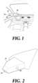
FIG. 1 is a perspective view of a vehicle on which a side camera for a vehicle is mounted according to one embodiment of the present disclosure. -
FIG. 2 is a perspective view of the side camera for a vehicle according to one embodiment of the present disclosure. -
FIG. 3 is a block diagram of the side camera for a vehicle according to one embodiment of the present disclosure. -
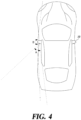
FIG. 4 is a view for describing fields of view (FOVs) of a blind-spot view camera and a surround view camera (SVC) disposed in the side camera for a vehicle. -
FIG. 5 shows images for describing a process of correcting an image captured by the SVC. -
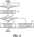
FIG. 6 is a flowchart of a method of controlling a side camera for a vehicle according to one embodiment of the present disclosure. - Some embodiments of the present disclosure will now be described in detail with reference to the illustrative drawings. It should be noted that, when reference numerals are added to the components in each drawing, the same components have the same numerals as possible, even if they are shown on different drawings. In the description of the present disclosure, a detailed description of a related known configuration or function is omitted when it is determined that the gist of the disclosure can be made.
- In describing the components of the embodiments according to the present disclosure, reference numerals such as first, second, i), ii), a), and b) may be used. Such symbols are only for distinguishing the components from other components, and the nature or order of the components is not limited by the symbols. When a portion in the specification is referred to as "comprising" or "including" a component, it means that the component may further comprise other components rather than excluding other components unless explicitly stated to the contrary.
-
FIG. 1 is a perspective view of a vehicle on which a side camera for a vehicle according to one embodiment of the present disclosure is mounted.FIG. 2 is a perspective view of the side camera for a vehicle according to one embodiment of the present disclosure.FIG. 3 is a block diagram of the side camera for a vehicle according to one embodiment of the present disclosure.FIG. 4 is a view for describing fields of view (FOVs) of a blind-spot view camera and a surround view camera (SVC) disposed in the side camera for a vehicle.FIG. 5 shows images for describing a process of correcting an image captured by the SVC. - Referring to
FIGS. 1 to 3 , the side camera for a vehicle includes all or some of amain body 10, a blind-spot view camera 20, anSVC 30, a blind-spot view monitor 40, and acontroller 50. - The
main body 10 includes a housing space therein and is installed at each of left-hand and right-hand sides of a vehicle. Themain body 10 may be formed as a streamlined type to minimize air resistance during traveling. - At least a portion of the blind-
spot view camera 20 is accommodated in themain body 10 and configured to photograph a view in a lateral direction behind the vehicle. For example, as shown inFIG. 2 , the blind-spot view camera 20 may be accommodated inside themain body 10. In order for the blind-spot view camera 20 to photograph a view in a lateral direction behind the vehicle, a lens of the blind-spot view camera 20 may be provided to face the rear side of the vehicle. -
FIG. 4 shows angles of view of the blind-spot view camera 20 and theSVC 30. A horizontal field of view (HFOV) A of the blind-spot view camera 20 is in a range of 50° to 80°, and a vertical field of view (VFOV) thereof is in a range of 20° to 40°. Since the blind-spot view camera 20 is used to replace an existing side mirror, a rear side range, which is checkable by a driver during traveling, is increased about two-fold or more. - The
SVC 30 is disposed in themain body 10 and designed to photograph an entire range of both views in a lateral direction from the vehicle. TheSVC 30 may be disposed in themain body 10 to face a direction perpendicular to a longitudinal direction of the vehicle. Here, an HFOV B of theSVC 30 is in a range of 180° to 200°, and a VFOV thereof is in a range of 120° to 160°. TheSVC 30 may photograph an entire range of a view in a lateral direction from the vehicle using a wide FOV. The SVC 30 is generally used to detect obstacles when parking a vehicle or traveling along a narrow road. - The blind-
spot view monitor 40 is a display device which displays information about an image captured by the blind-spot view camera 20. That is, the blind-spot view monitor 40 and the blind-spot view camera 20 replace existing side mirrors for a vehicle. One blind-spot view monitor 40 is disposed at each of front left-hand and right-hand sides inside the vehicle to display an image captured by the blind-spot view camera 20 disposed at each of both sides of the vehicle. - The
controller 50 is disposed inside the vehicle and is also referred to as an electronic control unit (ECU). Thecontroller 50 includes a hardware processor and a memory, and commands for executing thecontroller 50 and a look-up table (LUT) are stored in the memory. However, the present disclosure is not limited thereto, and all configurations for controlling overall operations of the vehicle may be included. Thecontroller 50 performs control to process an image captured by the blind-spot view camera 20 and transmit a screen to the blind-spot view monitor 40 and detects whether one or more of the blind-spot view camera 20 and the blind-spot view monitor 40 have failed. When a failure occurs in one or more of the blind-spot view camera 20 and the blind-spot view monitor 40, thecontroller 50 performs backup control using another display device other than the blind-spot monitor in the vehicle or theSVC 30 so as to secure a rear side field of view of the vehicle. - The
controller 50 may include afailure detector 51 and animage processor 52. Thefailure detector 51 periodically detects a failure state of the blind-spot view camera 20 and the blind-spot view monitor 40. While an ignition of the vehicle is turned on, thefailure detector 51 checks whether the blind-spot view camera 20 and the blind-spot view monitor 40 have failed at preset time intervals. When thefailure detector 51 detects that one or more of the blind-spot view camera 20 and the blind-spot view monitor 40 have failed, thefailure detector 51 transmits a failure detection signal to notify theimage processor 52 of the failure. In addition, when thefailure detector 51 detects a failure, a signal is transmitted to each device to notify a driver that the side camera for a vehicle is switched to an emergency system using a display device or a speaker device in the vehicle. The switch to the emergency system is performed by theimage processor 52 to be described below. Although the blind-spot view monitor 40 is illustrated inFIG. 1 as being separately disposed at each of left-hand and right-hand sides in the vehicle, the present disclosure is not limited thereto, and the blind-spot view monitor 40 may be disposed anywhere as long as the driver can view the blind-spot view monitor 40 without any difficulty during driving. - The
image processor 52 normally performs a calculation to process an image based on an image signal captured by the blind-spot view camera 20 and transmit a screen to the blind-spot view monitor 40. When theimage processor 52 receives the failure detection signal of the blind-spot view camera 20 or the blind-spot view monitor 40 from thefailure detector 51, theimage processor 52 performs image processing in response to the failure detection signal. - When it is determined that the blind-
spot view monitor 40 has failed, theimage processor 52 transmits a screen of an image captured by the blind-spot view camera 20 to another display device other than the blind-spot view monitor 40 within a driver's field of view instead of the blind-spot view monitor 40. - When it is determined that the blind-
spot view camera 20 has failed, theimage processor 52 receives image information from theSVC 30 rather than the blind-spot view camera 20, extracts only information about a rear side from the image information of theSVC 30, and transforms and transmits the extracted information to the blind-spot view monitor 40. TheSVC 30 is a wide angle camera, and thus, distortion of an image thereof occurs. In order for the driver to actually view a rear side of the vehicle with the blind-spot view camera 20, an undistortion process and a perspective transform process are required. - Referring to
FIG. 5 , a difference between an image of the blind-spot view camera 20 and an image of theSVC 30 can be confirmed. Part (a) ofFIG. 5 is an image acquired by photographing a view in a lateral direction behind the vehicle with the blind-spot view camera 20, and part (b) ofFIG. 5 is an image acquired by photographing an entire range of a view in a lateral direction from the vehicle with theSVC 30. Referring to part (b) ofFIG. 5 , the image is distorted so as to cover the entire range of the view in the lateral direction, and a rear side is a portion of the distorted image. When the distorted image is transmitted to a screen without any change, the driver cannot easily grasp information about the rear side during driving. Therefore, a rear side portion of the image captured by theSVC 30 is set as a region of interest (ROI), and an undistortion process and a perspective transform process are required for the set portion. After theimage processor 52 completes such an image transformation process, an image is transformed as shown inFIG. 5 . Theimage processor 52 transmits the transformed image to the blind-spot view monitor 40 to allow the driver to view the rear side of the vehicle even when the blind-spot view camera 20 has failed, thereby allowing the driver to avoid the risk of an accident. When theimage processor 52 performs the undistortion process and the perspective transform process, a volume of operation processing is increased, and thus, a high-performance hardware processor is required. Therefore, theimage processor 52 may be designed such that the preset LUT is stored in the memory of thecontroller 50 to transform an image based on the LUT. The LUT differs according to a mounting position of the blind-spot view camera 20 and theSVC 30 installed on the vehicle and a lens distortion ratio, and thus, a separate LUT should be set for each vehicle type. -
FIG. 6 is a flowchart of a method of controlling a side camera for a vehicle according to one embodiment of the present disclosure. - When an ignition of the vehicle is turned on, a
controller 50 periodically detects whether a CMS has failed (S61). Here, the CMS is an abbreviation of camera monitoring system and refers to a system designed such that a driver may use a blind-spot view camera 20 and a blind-spot view monitor 40 to monitor a situation of a rear side of a vehicle. - When the failure of the CMS is not detected, the
controller 50 does not proceed to a subsequent operation and periodically repeats operation S61 to detect whether the CMS has failed. - When the failure of the CMS is detected, the
controller 50 first notifies the driver that a side camera for a vehicle is switched to an emergency system (S62). The switch to the emergency system may be visually or audibly notified using a display device or a speaker device within a driver's field of view in the vehicle. Operation S62 is not an operation that is necessarily performed after operation S61 and may be performed after operation S63 to be described below. - After the driver is notified of the switch to the emergency system, the
controller 50 determines whether the blind-spot view monitor 40 has failed (S63). When thecontroller 50 determines that the blind-spot view monitor 40 has failed, a rear side image of the vehicle is transmitted to another display device other than the blind-spot view monitor in the vehicle rather than the blind-spot view monitor (S64). Here, another display device other than the blind-spot view monitor in the vehicle is a display device disposed within a driver's field of view. For example, another display device other than the blind-spot view monitor in the vehicle may be a digital cluster or a navigation display device disposed in a center fascia. - When the
controller 50 determines that the blind-spot view monitor 40 has not failed, thecontroller 50 determines that a failure has occurred in the same place as the blind-spot view camera 20 rather than the blind-spot view monitor 40, corrects an image using an image of theSVC 30 rather than an image captured by the blind-spot view camera 20, and then, performs replacement to display the corrected image on the blind-spot view monitor 40 (S65). Since an FOV of theSVC 30 is greater than an FOV of the blind-spot view camera 20 and distortion occurs in an image captured by theSVC 30, a correction process should be performed. As described above, in an image captured by theSVC 30, a portion related to a rear side of the vehicle is set as an ROI, and the image captured by theSVC 30 is subjected to an undistortion process and a perspective transform process and transformed to look like an image captured by the blind-spot view camera 20. Since many calculations are required for the undistortion process and the perspective transform process, in order to reduce the cost of a hardware processor, an LUT may be stored in a memory to correct the image captured by theSVC 30. Since transformation coordinates are calculated in advance in the LUT, an image can be corrected through coordinate transformation only with information of the LUT without calculation. - After the setting for securing a driver's rear side field of view of the vehicle using operation S64 or S65 is completed, the present algorithm is ended.
- Although operations are illustrated in
FIG. 6 as being sequentially performed, this is merely an exemplary description of the technical idea of one embodiment of the present disclosure. In other words, those skilled in the art to which one embodiment of the present disclosure belongs may appreciate that various modifications and changes can be made without departing from essential characteristics of one embodiment of the present disclosure, that is, the sequence illustrated inFIG. 6 can be changed and one or more operations of the operations can be performed in parallel. Thus,FIG. 6 is not limited to the temporal order. - As described above, according to the present embodiment, in a side camera for a vehicle and a method of controlling the same, when a blind-spot view camera has failed, an image captured by an SVC is transformed and transmitted to a blind-spot view monitor, or when the blind-spot view monitor has failed, an image captured by the blind-spot view camera is transmitted to another display device other than the blind-spot view monitor in the vehicle, thereby safely securing a driver's a rear side field of view during driving.
- Various embodiments of systems and techniques described herein can be realized with digital electronic circuits, integrated circuits, field programmable gate arrays (FPGAs), application specific integrated circuits (ASICs), computer hardware, firmware, software, and/or combinations thereof. The various embodiments can include implementation with one or more computer programs that are executable on a programmable system. The programmable system includes at least one programmable processor, which may be a special purpose processor or a general purpose processor, coupled to receive and transmit data and instructions from and to a storage system, at least one input device, and at least one output device. Computer programs (also known as programs, software, software applications, or code) include instructions for a programmable processor and are stored in a "computer-readable recording medium."
- The computer-readable recording medium may include all types of storage devices on which computer-readable data can be stored. The computer-readable recording medium may be a non-volatile or non-transitory medium such as a read-only memory (ROM), a random access memory (RAM), a compact disc ROM (CD-ROM), magnetic tape, a floppy disk, or an optical data storage device. In addition, the computer-readable recording medium may further include a transitory medium such as a data transmission medium. Furthermore, the computer-readable recording medium may be distributed over computer systems connected through a network, and computer-readable program code can be stored and executed in a distributive manner.
- Various embodiments of systems and techniques described herein can be realized by a programmable computer. Here, the computer includes a programmable processor, a data storage system (including a volatile memory, a non-volatile memory, another type of storage system, or a combination thereof), and at least one communication interface. For example, the programmable computer may be one of a server, a network device, a set-top box, an embedded device, a computer expansion module, a personal computer, a laptop, a personal data assistant (PDA), a cloud computing system, and a mobile device.
Claims (8)
- A side camera for a vehicle, comprising:a main body (10) disposed at a left-hand side and/or a right-hand side of the vehicle;a blind-spot view camera (20) of which at least a portion is accommodated in the main body (10) and being configured to photograph a view in a lateral and rearward directions of the vehicle;a surround view camera, SVC (30), of which at least a portion is accommodated in the main body (10) and being configured to photograph a view in a lateral direction of the vehicle; anda blind-spot view monitor (40) disposed inside the vehicle to transmit an image captured by the blind-spot view camera (20),wherein, when the blind-spot view camera (20) fails, an image transformation process is performed based on an image captured by the SVC (30) and transmitted to the blind-spot view monitor (40), andwhen the blind-spot view monitor (40) fails, an image captured by the blind-spot view camera (20) is transmitted to another display device in the vehicle other than the blind-spot view monitor (40),wherein in the image transformation process, a portion of the image captured by the SVC (30), which corresponds to a photographable range of the blind-spot view camera (20), is set as a region of interest, ROI, and an undistortion process and a perspective transform process are performed upon the portion set as the ROI for correction thereof and a corrected image is transmitted to the blind-spot view monitor (40) ),characterized in that the undistortion process and the perspective transform process being performed using a pre-stored look-up table, LUT, based on mounting positions of the blind-spot view camera (20) and the SVC (30) and a corresponding lens distortion ratio..
- The side camera of claim 1, further comprising:a failure detector (51) that periodically detects a failure state of the blind-spot view camera (20) and the blind-spot view monitor (40); andan image processor (52) that performs a calculation to process an image based on an image signal captured by the blind-spot view camera (20) and transmit a processed image to the blind-spot view monitor (40).
- The side camera of claim 1, wherein, when a fail in one or more of the blind-spot view camera (20) and the blind-spot view monitor (40) is detected, an operator of the vehicle is notified that the side camera is switched to an emergency system through at least one of a display device and a speaker device in the vehicle.
- The side camera of claim 1, wherein a horizontal field of view, HFOV, of the blind-spot view camera (20) is in a range of 50° to 80°, and an HFOV of the SVC is in a range of 180° to 200°.
- The side camera of claim 1, wherein a vertical field of view, VFOV, of the blind-spot view camera (20) is in a range of 20° to 40°, and
a VFOV of the SVC is in a range of 120° to 160°. - The side camera of claim 1, wherein said another display device other than the blind-spot view monitor (40) is at least one of a digital cluster and a navigation display device.
- A method of controlling a side camera for a vehicle which is switched to an emergency system when a blind-spot view camera (20) or a blind-spot view monitor (40) fails, the method comprising:a failure detecting operation of detecting whether the side camera fails;a notifying operation of notifying an operator that the side camera for a vehicle is switched to the emergency system when it is determined that the side camera for a vehicle fails;a failure determining operation of determining whether the blind-spot view monitor (40) fails; anda correction outputting operation of performing a connection to another display device other than the blind-spot view monitor (40) in a vehicle when it is determined that the blind-spot view monitor (40) fails, and transforming an image by using an image captured by a surround view camera, SVC (30), disposed in a main body (10) of the side camera for a vehicle and then outputting a corrected image to the blind-spot view monitor (40) when it is determined that the blind-spot view monitor (40) is not failed,wherein the correcting of the image includes:setting a portion of the image captured by the SVC (30), which corresponds to a photographable range of the blind-spot view camera, as a region of interest, ROI; andperforming an undistortion operation and a perspective transform operation on the portion set as the ROI to correct and transmit the image to the blind-spot view monitor (40), characterized in thatthe undistortion operation and the perspective transform operation being performed using a pre-stored look-up table, LUT,based on mounting positions of the blind-spot view camera (20) and the SVC (30) and a corresponding lens distortion ratio.
- The method of claim 7, wherein the notifying operation includes visually and audibly notifying the operator of the vehicle that the side camera for a vehicle is switched to the emergency system using at least one of a display device and a speaker device in the vehicle.
Applications Claiming Priority (1)
| Application Number | Priority Date | Filing Date | Title |
|---|---|---|---|
| KR1020200135261A KR102838352B1 (en) | 2020-10-19 | 2020-10-19 | Side Camera for Vehicle And Control Method Therefor |
Publications (2)
| Publication Number | Publication Date |
|---|---|
| EP3984823A1 EP3984823A1 (en) | 2022-04-20 |
| EP3984823B1 true EP3984823B1 (en) | 2025-07-02 |
Family
ID=78078039
Family Applications (1)
| Application Number | Title | Priority Date | Filing Date |
|---|---|---|---|
| EP21200640.7A Active EP3984823B1 (en) | 2020-10-19 | 2021-10-04 | Side camera for vehicle and method of controlling the same |
Country Status (4)
| Country | Link |
|---|---|
| US (1) | US11827149B2 (en) |
| EP (1) | EP3984823B1 (en) |
| KR (1) | KR102838352B1 (en) |
| CN (1) | CN114379462B (en) |
Families Citing this family (6)
| Publication number | Priority date | Publication date | Assignee | Title |
|---|---|---|---|---|
| KR20230111620A (en) * | 2022-01-17 | 2023-07-26 | 현대자동차주식회사 | Control method thereof, vehicle and camera monitoring apparatus |
| CN115002417A (en) * | 2022-05-31 | 2022-09-02 | 东风汽车集团股份有限公司 | Digital exterior rearview mirror system control method, device, device and readable storage medium |
| CN115712234B (en) * | 2022-10-25 | 2025-07-29 | 浙江衣拿智能科技股份有限公司 | On-orbit unit fault replacement method and device |
| CN116811736A (en) * | 2023-06-19 | 2023-09-29 | 长城汽车股份有限公司 | Fault processing method, device, vehicle and computer readable storage medium |
| KR20250001560A (en) * | 2023-06-29 | 2025-01-07 | 현대자동차주식회사 | Apparatus and Method for Surround View Monitoring With Fault Tolerance |
| KR102911151B1 (en) | 2023-11-06 | 2026-01-12 | 주식회사 서연이화 | Door for vehicle |
Family Cites Families (10)
| Publication number | Priority date | Publication date | Assignee | Title |
|---|---|---|---|---|
| JP4770943B2 (en) * | 2009-02-19 | 2011-09-14 | 株式会社デンソー | Outside-vehicle image display system and vehicle |
| US20130265431A1 (en) | 2009-02-19 | 2013-10-10 | Denso Corporation | Outside view monitor system for vehicle |
| US9139135B2 (en) * | 2012-09-07 | 2015-09-22 | Musaid A. ASSAF | System and method that minimizes hazards of blind spots while driving |
| JP6349637B2 (en) * | 2013-07-11 | 2018-07-04 | 株式会社デンソー | Image synthesizer for vehicles |
| EP3292024A4 (en) | 2015-05-06 | 2018-06-20 | Magna Mirrors of America, Inc. | Vehicle vision system with blind zone display and alert system |
| KR101766077B1 (en) * | 2015-12-08 | 2017-08-07 | 현대자동차주식회사 | System and Method for Providing Vehicle Around View |
| KR101795180B1 (en) * | 2015-12-11 | 2017-12-01 | 현대자동차주식회사 | Car side and rear monitoring system having fail safe function and method for the same |
| KR102105657B1 (en) | 2019-04-17 | 2020-04-29 | 김태훈 | Side Omnidirectional Camera for Vehicle |
| CN210139816U (en) * | 2019-06-24 | 2020-03-13 | 中寰卫星导航通信有限公司 | Vehicle vision blind area monitoring system and vehicle |
| KR20210011556A (en) * | 2019-07-22 | 2021-02-02 | 현대자동차주식회사 | Apparatus for controlling a vehicle, system having the same and method thereof |
-
2020
- 2020-10-19 KR KR1020200135261A patent/KR102838352B1/en active Active
-
2021
- 2021-09-17 US US17/478,872 patent/US11827149B2/en active Active
- 2021-10-04 EP EP21200640.7A patent/EP3984823B1/en active Active
- 2021-10-14 CN CN202111196934.3A patent/CN114379462B/en active Active
Also Published As
| Publication number | Publication date |
|---|---|
| EP3984823A1 (en) | 2022-04-20 |
| US11827149B2 (en) | 2023-11-28 |
| CN114379462A (en) | 2022-04-22 |
| KR102838352B1 (en) | 2025-07-24 |
| KR20220051880A (en) | 2022-04-27 |
| CN114379462B (en) | 2024-03-26 |
| US20220118908A1 (en) | 2022-04-21 |
Similar Documents
| Publication | Publication Date | Title |
|---|---|---|
| EP3984823B1 (en) | Side camera for vehicle and method of controlling the same | |
| US11242066B2 (en) | Vehicle control apparatus and vehicle control system and vehicle control method thereof | |
| CN210133061U (en) | A vehicle rearview mirror system and vehicle | |
| JP2012034076A (en) | Visual assistance system for vehicle, and vehicle provided with the same | |
| US20150193916A1 (en) | Image distortion compensating apparatus and operating method thereof | |
| KR101795180B1 (en) | Car side and rear monitoring system having fail safe function and method for the same | |
| US20190118711A1 (en) | Multiple camera control system and method for controlling output of multiple camera image | |
| EP4395356A1 (en) | Image capturing device, movable apparatus, and storage medium | |
| US12423986B2 (en) | Image capturing apparatus and vehicle | |
| US20160297363A1 (en) | Vehicular viewing device | |
| US12552319B2 (en) | Apparatus and method for blind-spot monitoring of vehicle based on rear camera | |
| KR20160050439A (en) | Method for adjusting output video of rear camera for vehicles | |
| KR102457633B1 (en) | Apparatus for real-time road condition check of vehicle front on the right outdoor side | |
| GB2402013A (en) | Automatic focal length control | |
| KR20160034681A (en) | Environment monitoring apparatus and method for vehicle | |
| KR102368609B1 (en) | Camera Monitor System For Vehicle and Fail-Safe Method thereof | |
| JP2019180074A (en) | Driving support system, image processing device, and image processing method | |
| KR20250001560A (en) | Apparatus and Method for Surround View Monitoring With Fault Tolerance | |
| CN104097572A (en) | Driving assistance device and method thereof | |
| TWI904783B (en) | System and method for pedestrian detection and pedestrian warning | |
| KR20170093499A (en) | Environment monitoring apparatus and method for vehicle | |
| JP2024081026A (en) | Vehicle display device | |
| US20250178534A1 (en) | Movable apparatus | |
| KR20210053382A (en) | Vision head up display system with deep neural networks vision technology | |
| KR20140117807A (en) | Side mirror camera for vehicle |
Legal Events
| Date | Code | Title | Description |
|---|---|---|---|
| PUAI | Public reference made under article 153(3) epc to a published international application that has entered the european phase |
Free format text: ORIGINAL CODE: 0009012 |
|
| STAA | Information on the status of an ep patent application or granted ep patent |
Free format text: STATUS: REQUEST FOR EXAMINATION WAS MADE |
|
| 17P | Request for examination filed |
Effective date: 20211004 |
|
| AK | Designated contracting states |
Kind code of ref document: A1 Designated state(s): AL AT BE BG CH CY CZ DE DK EE ES FI FR GB GR HR HU IE IS IT LI LT LU LV MC MK MT NL NO PL PT RO RS SE SI SK SM TR |
|
| RBV | Designated contracting states (corrected) |
Designated state(s): AL AT BE BG CH CY CZ DE DK EE ES FI FR GB GR HR HU IE IS IT LI LT LU LV MC MK MT NL NO PL PT RO RS SE SI SK SM TR |
|
| STAA | Information on the status of an ep patent application or granted ep patent |
Free format text: STATUS: EXAMINATION IS IN PROGRESS |
|
| 17Q | First examination report despatched |
Effective date: 20230313 |
|
| GRAP | Despatch of communication of intention to grant a patent |
Free format text: ORIGINAL CODE: EPIDOSNIGR1 |
|
| STAA | Information on the status of an ep patent application or granted ep patent |
Free format text: STATUS: GRANT OF PATENT IS INTENDED |
|
| INTG | Intention to grant announced |
Effective date: 20250128 |
|
| P01 | Opt-out of the competence of the unified patent court (upc) registered |
Free format text: CASE NUMBER: APP_8461/2025 Effective date: 20250219 |
|
| GRAS | Grant fee paid |
Free format text: ORIGINAL CODE: EPIDOSNIGR3 |
|
| GRAA | (expected) grant |
Free format text: ORIGINAL CODE: 0009210 |
|
| STAA | Information on the status of an ep patent application or granted ep patent |
Free format text: STATUS: THE PATENT HAS BEEN GRANTED |
|
| AK | Designated contracting states |
Kind code of ref document: B1 Designated state(s): AL AT BE BG CH CY CZ DE DK EE ES FI FR GB GR HR HU IE IS IT LI LT LU LV MC MK MT NL NO PL PT RO RS SE SI SK SM TR |
|
| REG | Reference to a national code |
Ref country code: GB Ref legal event code: FG4D |
|
| REG | Reference to a national code |
Ref country code: CH Ref legal event code: EP |
|
| REG | Reference to a national code |
Ref country code: DE Ref legal event code: R096 Ref document number: 602021033238 Country of ref document: DE |
|
| REG | Reference to a national code |
Ref country code: IE Ref legal event code: FG4D |
|
| PGFP | Annual fee paid to national office [announced via postgrant information from national office to epo] |
Ref country code: GB Payment date: 20250922 Year of fee payment: 5 |
|
| PGFP | Annual fee paid to national office [announced via postgrant information from national office to epo] |
Ref country code: FR Payment date: 20250925 Year of fee payment: 5 |
|
| REG | Reference to a national code |
Ref country code: NL Ref legal event code: MP Effective date: 20250702 |
|
| PG25 | Lapsed in a contracting state [announced via postgrant information from national office to epo] |
Ref country code: PT Free format text: LAPSE BECAUSE OF FAILURE TO SUBMIT A TRANSLATION OF THE DESCRIPTION OR TO PAY THE FEE WITHIN THE PRESCRIBED TIME-LIMIT Effective date: 20251103 |
|
| PG25 | Lapsed in a contracting state [announced via postgrant information from national office to epo] |
Ref country code: NL Free format text: LAPSE BECAUSE OF FAILURE TO SUBMIT A TRANSLATION OF THE DESCRIPTION OR TO PAY THE FEE WITHIN THE PRESCRIBED TIME-LIMIT Effective date: 20250702 |
|
| REG | Reference to a national code |
Ref country code: AT Ref legal event code: MK05 Ref document number: 1808890 Country of ref document: AT Kind code of ref document: T Effective date: 20250702 |
|
| PG25 | Lapsed in a contracting state [announced via postgrant information from national office to epo] |
Ref country code: IS Free format text: LAPSE BECAUSE OF FAILURE TO SUBMIT A TRANSLATION OF THE DESCRIPTION OR TO PAY THE FEE WITHIN THE PRESCRIBED TIME-LIMIT Effective date: 20251102 |
|
| PGFP | Annual fee paid to national office [announced via postgrant information from national office to epo] |
Ref country code: DE Payment date: 20250922 Year of fee payment: 5 |
|
| PG25 | Lapsed in a contracting state [announced via postgrant information from national office to epo] |
Ref country code: NO Free format text: LAPSE BECAUSE OF FAILURE TO SUBMIT A TRANSLATION OF THE DESCRIPTION OR TO PAY THE FEE WITHIN THE PRESCRIBED TIME-LIMIT Effective date: 20251002 |
|
| REG | Reference to a national code |
Ref country code: LT Ref legal event code: MG9D |
|
| PG25 | Lapsed in a contracting state [announced via postgrant information from national office to epo] |
Ref country code: AT Free format text: LAPSE BECAUSE OF FAILURE TO SUBMIT A TRANSLATION OF THE DESCRIPTION OR TO PAY THE FEE WITHIN THE PRESCRIBED TIME-LIMIT Effective date: 20250702 |
|
| PG25 | Lapsed in a contracting state [announced via postgrant information from national office to epo] |
Ref country code: FI Free format text: LAPSE BECAUSE OF FAILURE TO SUBMIT A TRANSLATION OF THE DESCRIPTION OR TO PAY THE FEE WITHIN THE PRESCRIBED TIME-LIMIT Effective date: 20250702 |
|
| PG25 | Lapsed in a contracting state [announced via postgrant information from national office to epo] |
Ref country code: HR Free format text: LAPSE BECAUSE OF FAILURE TO SUBMIT A TRANSLATION OF THE DESCRIPTION OR TO PAY THE FEE WITHIN THE PRESCRIBED TIME-LIMIT Effective date: 20250702 |
|
| PG25 | Lapsed in a contracting state [announced via postgrant information from national office to epo] |
Ref country code: GR Free format text: LAPSE BECAUSE OF FAILURE TO SUBMIT A TRANSLATION OF THE DESCRIPTION OR TO PAY THE FEE WITHIN THE PRESCRIBED TIME-LIMIT Effective date: 20251003 |
|
| PG25 | Lapsed in a contracting state [announced via postgrant information from national office to epo] |
Ref country code: CZ Free format text: LAPSE BECAUSE OF FAILURE TO SUBMIT A TRANSLATION OF THE DESCRIPTION OR TO PAY THE FEE WITHIN THE PRESCRIBED TIME-LIMIT Effective date: 20250702 Ref country code: SE Free format text: LAPSE BECAUSE OF FAILURE TO SUBMIT A TRANSLATION OF THE DESCRIPTION OR TO PAY THE FEE WITHIN THE PRESCRIBED TIME-LIMIT Effective date: 20250702 |
|
| PG25 | Lapsed in a contracting state [announced via postgrant information from national office to epo] |
Ref country code: LV Free format text: LAPSE BECAUSE OF FAILURE TO SUBMIT A TRANSLATION OF THE DESCRIPTION OR TO PAY THE FEE WITHIN THE PRESCRIBED TIME-LIMIT Effective date: 20250702 |
|
| PG25 | Lapsed in a contracting state [announced via postgrant information from national office to epo] |
Ref country code: BG Free format text: LAPSE BECAUSE OF FAILURE TO SUBMIT A TRANSLATION OF THE DESCRIPTION OR TO PAY THE FEE WITHIN THE PRESCRIBED TIME-LIMIT Effective date: 20250702 Ref country code: PL Free format text: LAPSE BECAUSE OF FAILURE TO SUBMIT A TRANSLATION OF THE DESCRIPTION OR TO PAY THE FEE WITHIN THE PRESCRIBED TIME-LIMIT Effective date: 20250702 |
|
| PG25 | Lapsed in a contracting state [announced via postgrant information from national office to epo] |
Ref country code: RS Free format text: LAPSE BECAUSE OF FAILURE TO SUBMIT A TRANSLATION OF THE DESCRIPTION OR TO PAY THE FEE WITHIN THE PRESCRIBED TIME-LIMIT Effective date: 20251002 |
|
| PG25 | Lapsed in a contracting state [announced via postgrant information from national office to epo] |
Ref country code: ES Free format text: LAPSE BECAUSE OF FAILURE TO SUBMIT A TRANSLATION OF THE DESCRIPTION OR TO PAY THE FEE WITHIN THE PRESCRIBED TIME-LIMIT Effective date: 20250702 |
|
| PG25 | Lapsed in a contracting state [announced via postgrant information from national office to epo] |
Ref country code: RO Free format text: LAPSE BECAUSE OF FAILURE TO SUBMIT A TRANSLATION OF THE DESCRIPTION OR TO PAY THE FEE WITHIN THE PRESCRIBED TIME-LIMIT Effective date: 20250702 |
|
| PG25 | Lapsed in a contracting state [announced via postgrant information from national office to epo] |
Ref country code: SM Free format text: LAPSE BECAUSE OF FAILURE TO SUBMIT A TRANSLATION OF THE DESCRIPTION OR TO PAY THE FEE WITHIN THE PRESCRIBED TIME-LIMIT Effective date: 20250702 |
|
| PG25 | Lapsed in a contracting state [announced via postgrant information from national office to epo] |
Ref country code: DK Free format text: LAPSE BECAUSE OF FAILURE TO SUBMIT A TRANSLATION OF THE DESCRIPTION OR TO PAY THE FEE WITHIN THE PRESCRIBED TIME-LIMIT Effective date: 20250702 |
|
| PG25 | Lapsed in a contracting state [announced via postgrant information from national office to epo] |
Ref country code: IT Free format text: LAPSE BECAUSE OF FAILURE TO SUBMIT A TRANSLATION OF THE DESCRIPTION OR TO PAY THE FEE WITHIN THE PRESCRIBED TIME-LIMIT Effective date: 20250702 |
|
| PG25 | Lapsed in a contracting state [announced via postgrant information from national office to epo] |
Ref country code: EE Free format text: LAPSE BECAUSE OF FAILURE TO SUBMIT A TRANSLATION OF THE DESCRIPTION OR TO PAY THE FEE WITHIN THE PRESCRIBED TIME-LIMIT Effective date: 20250702 Ref country code: SK Free format text: LAPSE BECAUSE OF FAILURE TO SUBMIT A TRANSLATION OF THE DESCRIPTION OR TO PAY THE FEE WITHIN THE PRESCRIBED TIME-LIMIT Effective date: 20250702 |