EP3984683A1 - Bonded joint, and method for manufacturing bonded joint - Google Patents
Bonded joint, and method for manufacturing bonded joint Download PDFInfo
- Publication number
- EP3984683A1 EP3984683A1 EP20826449.9A EP20826449A EP3984683A1 EP 3984683 A1 EP3984683 A1 EP 3984683A1 EP 20826449 A EP20826449 A EP 20826449A EP 3984683 A1 EP3984683 A1 EP 3984683A1
- Authority
- EP
- European Patent Office
- Prior art keywords
- sheet
- steel
- joint
- steel sheet
- steel material
- Prior art date
- Legal status (The legal status is an assumption and is not a legal conclusion. Google has not performed a legal analysis and makes no representation as to the accuracy of the status listed.)
- Granted
Links
Images



Classifications
-
- B—PERFORMING OPERATIONS; TRANSPORTING
- B23—MACHINE TOOLS; METAL-WORKING NOT OTHERWISE PROVIDED FOR
- B23K—SOLDERING OR UNSOLDERING; WELDING; CLADDING OR PLATING BY SOLDERING OR WELDING; CUTTING BY APPLYING HEAT LOCALLY, e.g. FLAME CUTTING; WORKING BY LASER BEAM
- B23K20/00—Non-electric welding by applying impact or other pressure, with or without the application of heat, e.g. cladding or plating
- B23K20/12—Non-electric welding by applying impact or other pressure, with or without the application of heat, e.g. cladding or plating the heat being generated by friction; Friction welding
- B23K20/122—Non-electric welding by applying impact or other pressure, with or without the application of heat, e.g. cladding or plating the heat being generated by friction; Friction welding using a non-consumable tool, e.g. friction stir welding
- B23K20/1245—Non-electric welding by applying impact or other pressure, with or without the application of heat, e.g. cladding or plating the heat being generated by friction; Friction welding using a non-consumable tool, e.g. friction stir welding characterised by the apparatus
-
- B—PERFORMING OPERATIONS; TRANSPORTING
- B23—MACHINE TOOLS; METAL-WORKING NOT OTHERWISE PROVIDED FOR
- B23K—SOLDERING OR UNSOLDERING; WELDING; CLADDING OR PLATING BY SOLDERING OR WELDING; CUTTING BY APPLYING HEAT LOCALLY, e.g. FLAME CUTTING; WORKING BY LASER BEAM
- B23K20/00—Non-electric welding by applying impact or other pressure, with or without the application of heat, e.g. cladding or plating
- B23K20/12—Non-electric welding by applying impact or other pressure, with or without the application of heat, e.g. cladding or plating the heat being generated by friction; Friction welding
-
- B—PERFORMING OPERATIONS; TRANSPORTING
- B23—MACHINE TOOLS; METAL-WORKING NOT OTHERWISE PROVIDED FOR
- B23K—SOLDERING OR UNSOLDERING; WELDING; CLADDING OR PLATING BY SOLDERING OR WELDING; CUTTING BY APPLYING HEAT LOCALLY, e.g. FLAME CUTTING; WORKING BY LASER BEAM
- B23K20/00—Non-electric welding by applying impact or other pressure, with or without the application of heat, e.g. cladding or plating
- B23K20/22—Non-electric welding by applying impact or other pressure, with or without the application of heat, e.g. cladding or plating taking account of the properties of the materials to be welded
- B23K20/227—Non-electric welding by applying impact or other pressure, with or without the application of heat, e.g. cladding or plating taking account of the properties of the materials to be welded with ferrous layer
-
- B—PERFORMING OPERATIONS; TRANSPORTING
- B23—MACHINE TOOLS; METAL-WORKING NOT OTHERWISE PROVIDED FOR
- B23K—SOLDERING OR UNSOLDERING; WELDING; CLADDING OR PLATING BY SOLDERING OR WELDING; CUTTING BY APPLYING HEAT LOCALLY, e.g. FLAME CUTTING; WORKING BY LASER BEAM
- B23K20/00—Non-electric welding by applying impact or other pressure, with or without the application of heat, e.g. cladding or plating
- B23K20/26—Auxiliary equipment
-
- B—PERFORMING OPERATIONS; TRANSPORTING
- B23—MACHINE TOOLS; METAL-WORKING NOT OTHERWISE PROVIDED FOR
- B23K—SOLDERING OR UNSOLDERING; WELDING; CLADDING OR PLATING BY SOLDERING OR WELDING; CUTTING BY APPLYING HEAT LOCALLY, e.g. FLAME CUTTING; WORKING BY LASER BEAM
- B23K2103/00—Materials to be soldered, welded or cut
- B23K2103/02—Iron or ferrous alloys
- B23K2103/04—Steel or steel alloys
-
- F—MECHANICAL ENGINEERING; LIGHTING; HEATING; WEAPONS; BLASTING
- F16—ENGINEERING ELEMENTS AND UNITS; GENERAL MEASURES FOR PRODUCING AND MAINTAINING EFFECTIVE FUNCTIONING OF MACHINES OR INSTALLATIONS; THERMAL INSULATION IN GENERAL
- F16B—DEVICES FOR FASTENING OR SECURING CONSTRUCTIONAL ELEMENTS OR MACHINE PARTS TOGETHER, e.g. NAILS, BOLTS, CIRCLIPS, CLAMPS, CLIPS OR WEDGES; JOINTS OR JOINTING
- F16B5/00—Joining sheets or plates, e.g. panels, to one another or to strips or bars parallel to them
- F16B5/08—Joining sheets or plates, e.g. panels, to one another or to strips or bars parallel to them by means of welds or the like
-
- F—MECHANICAL ENGINEERING; LIGHTING; HEATING; WEAPONS; BLASTING
- F16—ENGINEERING ELEMENTS AND UNITS; GENERAL MEASURES FOR PRODUCING AND MAINTAINING EFFECTIVE FUNCTIONING OF MACHINES OR INSTALLATIONS; THERMAL INSULATION IN GENERAL
- F16B—DEVICES FOR FASTENING OR SECURING CONSTRUCTIONAL ELEMENTS OR MACHINE PARTS TOGETHER, e.g. NAILS, BOLTS, CIRCLIPS, CLAMPS, CLIPS OR WEDGES; JOINTS OR JOINTING
- F16B9/00—Connections of rods or tubular parts to flat surfaces at an angle
- F16B9/01—Welded or bonded connections
Definitions
- the present invention relates to a joint jointed by friction welding.
- PTL 1 discloses the art of joining two sheet materials differing in strength, such as an aluminum sheet and steel sheet, by a process of friction welding using a rivet or other joining element (that is, a connecting element having a head part and shaft part). Specifically, the art of joining two sheet materials with different strengths through the following process is disclosed.
- the two sheet materials are superposed with the sheet material with the lower strength as the top sheet, a connecting element supported by a holder is set on the top surface of the top sheet, and the connecting element is made to rotate while making it move downward toward the inside part of the top sheet and press against it.
- rotation of the connecting element causes strong friction to occur between the connecting element and the top sheet whereby the front end part of the connecting element is heated, so the top sheet softens and it becomes possible for the connecting element to penetrate the top sheet.
- the present invention relates to a joint jointed by friction welding and has as its object the provision of a joint excellent in joint strength.
- a hard phase mainly martensite phase P M
- a soft phase softer than the hard phase mainly ferrite phase P F
- the inventors discovered that by making the metal structure at the end part of the jointed part at the steel sheet a predetermined homogeneous structure, local strain concentration is eliminated and the joint strength as a joint is improved and thereby completed the present invention.
- the "end part of the jointed part” indicates a corner part formed by the surface of the steel sheet and the plastically deformed steel sheet (part shown by notation X 1 of FIG. 1A and FIG. 3A ).
- the "metal structure of the end part of the jointed part” indicates the metal structure inside the steel sheet at 30 ⁇ m inside from the end part of the jointed part on the extension line of the surface of the steel sheet (part shown by notation X 2 of FIG. 1A and FIG. 3A ).
- the joint 10 is comprised of a rod-shaped steel material 1 having a circular columnar shaft part and a steel sheet 2. A lower side front end part of the shaft part of the steel material 1 (bottom surface) and the steel sheet 2 are jointed by friction welding.
- the steel sheet 2 of the joint 10 has a metal structure with a martensite area ratio of 80% or more at the end part of the jointed part P of the lower side front end part of the shaft part of the steel material 1 and the steel sheet 2.
- the metal structure of the end part of the jointed part P at the steel sheet 2 is a metal structure with a martensite area ratio of 80% or more, that is, a metal structure comprised of homogeneous martensite P M where local strain concentration at the interface of a soft phase and a hard phase hardly ever occurs, so excellent joint strength can be exhibited.
- the joint 10 not only achieves a high joint strength due to the homogeneous metal structure of the above-mentioned martensite P M , but also can reduce the variation in joint strength.
- the metal structure with a martensite area ratio of 80% or more can contain retained austenite and other phases besides martensite P M if a 20% or less area ratio. Further, the metal structure of the end part of the jointed part preferably has an area ratio of martensite P M of 90% or more, more preferably 95% or more. If the area ratio of martensite P M is 90% or more or further 95% or more, a high joint strength can be obtained more stably.
- a metal structure with a martensite area ratio of 80% or more of an end part of a jointed part at a steel sheet can be confirmed by cutting the jointed part of the joint along the sheet thickness direction, polishing and etching the cut surface, then examining the surface enlarged by a scanning electron microscope.
- a field of observation of a size of 20 ⁇ m ⁇ 20 ⁇ m or more centered on a position inside the steel sheet by a depth of 30 ⁇ m from the end part of the jointed part on an extension line of the surface of the steel sheet (that is, the part shown by notation X 2 of FIG. 1A and FIG. 3A ) is observed enlarged.
- Such a metal structure with a martensite area ratio of 80% or more can be obtained by friction welding the steel material and steel sheet under the later explained predetermined pressing force and rotational speed conditions to thereby make the base material structure of the steel sheet (specifically, the structure of the end part of the jointed part) transform to martensite through austenite transformation.
- Such a metal structure with a martensite area ratio of 80% or more can be obtained by heating and quenching (hardening) the joint as a whole after friction welding the steel material and steel sheet.
- heating and quenching of the joint as a whole are not preferable since even the base material part not subjected to the heat history of the joining operation ends up being hardened and the properties of the base material end up being damaged. Therefore, from the viewpoint of not having heating and quenching of the joint as a whole cause widespread damage to the properties of the base material, the presence of a HAZ softened part is preferable.
- the joint as a whole not being heated and quenched can be confirmed by checking for the presence of a HAZ softened part formed at the time of joining.
- a "HAZ softened part” indicates a region which is tempered by the heat input at the time of joining_and is lower in hardness than the base material part which is not affected by the heat. Therefore, if heating and quenching the joint as a whole after friction welding, the HAZ softened part is also hardened so the HAZ softened part disappears.
- the presence of a HAZ softened part can be confirmed by measuring the hardness distribution from the base material part to the center of the friction welded part at a position of 0.2 mm depth in the sheet thickness direction from the friction welded surface of the steel sheet.
- the measurement load at this time is made, for example, 200 g and the measurement interval is made 0.2 mm.
- the hardness becomes smaller the closer to the center of the friction welded part from the base material part. If a high hardness region hardened by the friction welding is seen after this, it can be judged that a HAZ softened part is present and simultaneously it can be judged that it has not been hardened by heating and quenching of the joint as a whole.
- the steel sheet preferably contains carbon in 0.15 mass% or more.
- the content of carbon is more preferably 0.20 mass% or more, more preferably 0.25 mass% or more.
- the joint of the present invention can, for example, by obtained by a method of manufacture including the following friction welding step.
- the diameters of the rods (shaft parts of steel materials), the pressing forces and rotational speeds at the time of friction welding, the metal structures of the jointed parts, and the results of measurement of the joint strengths are as shown in the following Table 1.
- the present invention has a high applicability in industry.
Landscapes
- Engineering & Computer Science (AREA)
- Mechanical Engineering (AREA)
- Pressure Welding/Diffusion-Bonding (AREA)
Abstract
Description
- The present invention relates to a joint jointed by friction welding.
- As means for joining a plurality of metal sheets, the art is known of joining a superposed plurality of metal sheets using rivets or other connecting members.
- In particular, in recent years, the art of joining a superposed top sheet and bottom sheet by making a connecting element rotate while pressing it against the top surface of the top sheet so as to pass it through the top sheet and thereby friction weld the connecting element and the bottom sheet has been studied.
- For example,
PTL 1 discloses the art of joining two sheet materials differing in strength, such as an aluminum sheet and steel sheet, by a process of friction welding using a rivet or other joining element (that is, a connecting element having a head part and shaft part). Specifically, the art of joining two sheet materials with different strengths through the following process is disclosed. - That is, the two sheet materials are superposed with the sheet material with the lower strength as the top sheet, a connecting element supported by a holder is set on the top surface of the top sheet, and the connecting element is made to rotate while making it move downward toward the inside part of the top sheet and press against it. At this time, rotation of the connecting element causes strong friction to occur between the connecting element and the top sheet whereby the front end part of the connecting element is heated, so the top sheet softens and it becomes possible for the connecting element to penetrate the top sheet.
- If the front end part of the connecting element rotating while penetrating the top sheet in this way reaches the top surface of the bottom sheet, a process of friction welding proceeds between the shaft part of the connecting element and the bottom sheet whereby the shaft part of the connecting element and the bottom sheet are friction welded. Due to this, the connecting element and the bottom sheet are jointed at the friction welded part (jointed part) and the top sheet is secured between the head part of the connecting element and the bottom sheet.
- [PTL 1]
Japanese Unexamined Patent Publication No. 2011-62748 - Not limited to the art of this
PTL 1, in a joint formed by the art of friction welding a steel rod to a steel sheet (friction stud welding) etc., there was the problem that if using a steel sheet with a particularly high carbon content (for example, high strength steel sheet with a tensile strength of over 980 MPa etc.), the strength of the friction welded part (jointed part) ended up falling and as a result the joint strength as a joint ended up decreasing. - Therefore, the present invention relates to a joint jointed by friction welding and has as its object the provision of a joint excellent in joint strength.
- The inventors investigated in detail the cause by which a joint jointed by friction welding falls in joint strength. It was thought that the cause was the metal structure near the jointed part of the steel sheet (end part of jointed part) formed by plastic deformation of the steel sheet, as shown in
FIG. 1 , being comprised of a nonhomogeneous metal structure of two phases including a hard phase (mainly martensite phase PM) and a soft phase softer than the hard phase (mainly ferrite phase PF) (below, simply referred to as "two phase structure"). It is believed that local strain easily concentrates at the interface of the hard phase and soft phase of the two phase structure and ductile fracture is easily caused. - Therefore, the inventors discovered that by making the metal structure at the end part of the jointed part at the steel sheet a predetermined homogeneous structure, local strain concentration is eliminated and the joint strength as a joint is improved and thereby completed the present invention.
- Here, the "end part of the jointed part" indicates a corner part formed by the surface of the steel sheet and the plastically deformed steel sheet (part shown by notation X1 of
FIG. 1A andFIG. 3A ). Further, the "metal structure of the end part of the jointed part" indicates the metal structure inside the steel sheet at 30 µm inside from the end part of the jointed part on the extension line of the surface of the steel sheet (part shown by notation X2 ofFIG. 1A andFIG. 3A ). - Specific aspects of the present invention are as follows:
- [1] A joint comprising a steel material having a shaft part and a steel sheet jointed to the steel material by friction welding, the steel sheet having a metal structure with a martensite area ratio of 80% or more at an end part of a jointed part with the shaft part of the steel material.
- [2] The joint according to [1], wherein the joint comprises a HAZ softened part.
- [3] The joint according to [1] or [2], wherein the steel sheet contains carbon in 0.15 mass% or more.
- [4] The joint according to any one of [1] to [3], wherein a top surface of the steel sheet has at least one sheet material among a plastic sheet and a metal sheet superposed on the top surface and the shaft part of the steel material is passed through the sheet material and jointed with the steel sheet by friction welding.
- [5] The joint according to [4], wherein the steel material has a head part with a cross-sectional diameter larger than the shaft part at an end part at an opposite side to the jointed part, and the sheet material is gripped between the steel sheet and the head part of the steel material.
- [6] The joint according to any one of [1] to [5] wherein a tensile strength of the steel sheet is 500 MPa or more.
- [7] A method of production of the joint according to any of [1] to [6] comprising a friction welding step of making the steel material press while rotating the steel material against a top surface of the steel sheet, in the friction welding step, a pressing force F (kN) and rotational speed R (rpm) when pressing the steel material against the top surface of the steel sheet satisfying the following formula (1) to formula (3):

When D≥12, R≥2000... (3).
The "D" in the formula (1) to formula (3) indicates a diameter (mm) of a circle of a vertical cross-section of the shaft part if the shaft part is a circular column and a diameter (mm) of a smallest enclosing circle of a polygonal shape of a vertical cross-section of the shaft part if the shaft part is a polygonal column. - [8] The method of manufacture of a joint according to [7], wherein a tensile strength of the steel sheet is 500 MPa or more.
- According to the present invention, it is possible to provide a joint jointed by friction welding which is excellent in joint strength.
-
-
FIGS. 1A and 1B are views showing a conventional joint 10' jointed by friction welding.FIG. 1A is a cross-sectional view of a jointed part P of the conventional joint 10' and parts near it, whileFIG. 1B is an electron micrograph showing a metal structure of an end part of the jointed part P at the conventional joint 10' (part shown by notation X2 ofFIG. 1A ). -
FIGS. 2A and 2B are schematic views for explaining the method of manufacture of ajoint 10 according to one embodiment of the present invention.FIG. 2A shows the state before thesteel material 1 andsteel sheet 2 start to be jointed, whileFIG. 2B shows the state of making thesteel material 1 rotate while making it move downward to press it against thesteel sheet 2. -
FIGS. 3A and 3B are views showing ajoint 10 according to one embodiment of the present invention.FIG. 3A is a cross-sectional view of a jointed part P of thejoint 10 and parts near it, whileFIG. 3B is an electron micrograph showing a metal structure of an end part of the jointed part P at the joint 10 (part shown by notation X2 ofFIG. 3A ). -
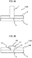
FIGS. 4A and 4B are schematic views for explaining a joint according to another embodiment of the present invention.FIG. 4A is a view showing a joint 10A comprised of asteel material 1 passed through a sheet material 3 (top sheet) and a steel sheet 2 (bottom sheet) jointed by friction welding, whileFIG. 4B is a view showing a joint 10B comprised of a rivet-shaped steel material 1B passed through a throughhole 31 of asheet material 3B (top sheet) and a steel sheet 2 (bottom sheet) jointed by friction welding. -
FIG. 5 is a schematically showing a steel material in the case where a lower side front end part of the shaft part is conical shaped as an example of a steel material able to be used for the joint of the present invention. -
FIG. 6 is a schematically showing a steel material in the case where a lower side front end part of the shaft part is spherical shaped as another example of a steel material able to be used for the joint of the present invention. - Below, preferred embodiments of the joint of the present invention will be explained in detail while referring to the drawings.
- As shown in
FIG. 3A , the joint 10 according to one embodiment of the present invention is comprised of a rod-shapedsteel material 1 having a circular columnar shaft part and asteel sheet 2. A lower side front end part of the shaft part of the steel material 1 (bottom surface) and thesteel sheet 2 are jointed by friction welding. - Further, the
steel sheet 2 of the joint 10, as shown inFIG. 3B , has a metal structure with a martensite area ratio of 80% or more at the end part of the jointed part P of the lower side front end part of the shaft part of thesteel material 1 and thesteel sheet 2. - In this way, in the joint 10 of the present embodiment, the metal structure of the end part of the jointed part P at the
steel sheet 2 is a metal structure with a martensite area ratio of 80% or more, that is, a metal structure comprised of homogeneous martensite PM where local strain concentration at the interface of a soft phase and a hard phase hardly ever occurs, so excellent joint strength can be exhibited. - Note that, the joint 10 not only achieves a high joint strength due to the homogeneous metal structure of the above-mentioned martensite PM , but also can reduce the variation in joint strength.
- The metal structure with a martensite area ratio of 80% or more can contain retained austenite and other phases besides martensite PM if a 20% or less area ratio. Further, the metal structure of the end part of the jointed part preferably has an area ratio of martensite PM of 90% or more, more preferably 95% or more. If the area ratio of martensite PM is 90% or more or further 95% or more, a high joint strength can be obtained more stably.
- Note that, a metal structure with a martensite area ratio of 80% or more of an end part of a jointed part at a steel sheet can be confirmed by cutting the jointed part of the joint along the sheet thickness direction, polishing and etching the cut surface, then examining the surface enlarged by a scanning electron microscope. In examining the surface after etching enlarged, a field of observation of a size of 20 µm×20 µm or more centered on a position inside the steel sheet by a depth of 30 µm from the end part of the jointed part on an extension line of the surface of the steel sheet (that is, the part shown by notation X2 of
FIG. 1A andFIG. 3A ) is observed enlarged. - Such a metal structure with a martensite area ratio of 80% or more can be obtained by friction welding the steel material and steel sheet under the later explained predetermined pressing force and rotational speed conditions to thereby make the base material structure of the steel sheet (specifically, the structure of the end part of the jointed part) transform to martensite through austenite transformation.
- Further, such a metal structure with a martensite area ratio of 80% or more can be obtained by heating and quenching (hardening) the joint as a whole after friction welding the steel material and steel sheet.
- However, heating and quenching of the joint as a whole are not preferable since even the base material part not subjected to the heat history of the joining operation ends up being hardened and the properties of the base material end up being damaged. Therefore, from the viewpoint of not having heating and quenching of the joint as a whole cause widespread damage to the properties of the base material, the presence of a HAZ softened part is preferable.
- The joint as a whole not being heated and quenched can be confirmed by checking for the presence of a HAZ softened part formed at the time of joining. A "HAZ softened part" indicates a region which is tempered by the heat input at the time of joining_and is lower in hardness than the base material part which is not affected by the heat. Therefore, if heating and quenching the joint as a whole after friction welding, the HAZ softened part is also hardened so the HAZ softened part disappears. The presence of a HAZ softened part can be confirmed by measuring the hardness distribution from the base material part to the center of the friction welded part at a position of 0.2 mm depth in the sheet thickness direction from the friction welded surface of the steel sheet. The measurement load at this time is made, for example, 200 g and the measurement interval is made 0.2 mm. In the measured hardness distribution, the hardness becomes smaller the closer to the center of the friction welded part from the base material part. If a high hardness region hardened by the friction welding is seen after this, it can be judged that a HAZ softened part is present and simultaneously it can be judged that it has not been hardened by heating and quenching of the joint as a whole.
- To obtain a metal structure with a martensite area ratio of 80% or more, the steel sheet preferably contains carbon in 0.15 mass% or more. The content of carbon is more preferably 0.20 mass% or more, more preferably 0.25 mass% or more.
- The joint of the present invention can, for example, by obtained by a method of manufacture including the following friction welding step.
- Note that, in explaining such a method of manufacture, the method of manufacture of the joint 10 of the above embodiment is used illustratively.
- As shown in
FIGS. 2A and 2B , thesteel material 1 is made to rotate while making it move to the lower side to make the lower side front end part of the shaft part of thesteel material 1 contact the top surface of thesteel sheet 2. By adjusting the rotational speed and pressing force of thesteel material 1 after the lower side front end part of the shaft part of thesteel material 1 contacts the top surface of thesteel sheet 2, it is possible to make heat of friction be generated between thesteel material 1 andsteel sheet 2 whereby the lower side front end part of the shaft part of thesteel material 1 and thesteel sheet 2 are friction welded. - Regarding the various conditions in this friction welding step, the inventors ran experiments changing the various pressing forces, rotational speeds, and radii of the steel materials for steel sheets of various constituents and expressed the obtained results by regression formulas.
- That is, a
steel material 1 where, in the friction welding step, a pressing force F (kN) and rotational speed R (rpm) when pressing it against the top surface of thesteel sheet 2 satisfies the following formula (1) to formula (3) is employed.
- When D<12, R≥36000/D-1000... (2)
- When D≥12, R≥2000... (3)
- The "D" in the formula (1) to formula (3) indicates a diameter (mm) of a circle of a vertical cross-section of the shaft part if the shaft part is a circular column and a diameter (mm) of a smallest enclosing circle of a polygonal shape of a vertical cross-section of the shaft part if the shaft part is a polygonal column.
- In this friction welding step, by friction welding the
steel material 1 andsteel sheet 2 by a specific pressing force and rotational speed satisfying the above formula (1) to formula (3), the heat input to thesteel sheet 2 rises and a friction welded part (jointed part P) is formed between the shaft part of thesteel material 1 and thesteel sheet 2. Along with this, the structure of the end part of the jointed part P at thesteel sheet 2 transforms to martensite through austenite transformation whereby a metal structure with the above-mentioned martensite area ratio of 80% or more is formed. - In this way, a joint 10 such as shown in
FIG. 3A comprised of asteel material 1 and asteel sheet 2 jointed through a jointed part P is obtained. - Note that, the pressing force and rotational speed are similar in embodiments where the steel material is other than a rod shape (for example, an embodiment of a rivet shape etc.)
- Further, if, as explained later, the joint includes a sheet material as the top sheet, in the same way as the above, the steel material can be made to rotate while pressing against the steel sheet by a specific pressing force and rotational speed satisfying the above formula (1) to formula (3) so as to obtain a similar joint.
- Note that, the upper limit value of the pressing force F is not particularly prescribed, but if the pressing force is high, the manufacturing facility ends up becoming larger in size, so 500 kN or less is preferable.
- Further, the upper limit value of the rotational speed R is not particularly prescribed, but raising the rotational speed under high pressing force conditions is difficult, so when D<12, it is preferably 15000 rpm or less and when D≥12, it is preferably 5000 rpm or less.
- Below, the various component members used for the joint of the present invention will be explained.
- In the joint 10 of the above-mentioned embodiment, as the steel material, a rod-shaped
steel material 1 having a circular columnar shaft part is illustratively used, but in the present invention, the shape of the steel material is not limited. For example, as the shape of the shaft part of the steel material, a circular column, polygonal column, etc. may be mentioned. Note that, to stably perform the friction welding, the shape of the shaft part of the steel material is preferably a circular column or pentagonal or higher regular polygonal column. - Therefore, as the steel material, for example, a rod-shaped steel material having a circular columnar or polygonal columnar shaft part, a rivet-shaped steel material having a circular columnar or polygonal columnar shaft part and a head part provided at an upper side end part of the shaft part and with a cross-sectional diameter larger than the shaft part, etc. may be used.
- That is, as the steel material, a rod, rivet, etc. generally used as a connecting element in the field can be employed. For example, one of a solid structure or hollow structure disclosed in the above-mentioned
PTL 1 etc. can be employed. - Note that, in the later mentioned joint 10B accordingly to another embodiment of the present invention shown in
FIG. 4B , a rivet-shapedsteel material 1B is used as the steel material. In this joint 10B, the rivet-shapedsteel material 1B has ashaft part 11 extending from the jointed part P and ahead part 12 positioned at an upper side end part of theshaft part 11 and having a cross-sectional diameter larger than theshaft part 11, so thesheet material 3B arranged at the top sheet can be gripped by thehead part 12 and steel sheet 2 (bottom sheet) of thesteel material 1B and more strongly fastened. Further, the joint strength of the friction welded part (jointed part P) of thesteel material 1B andsteel sheet 2 is also excellent, so it is possible to exhibit a more excellent joint strength as the joint of thesheet material 3B andsteel sheet 2. - If using such a rivet-shaped steel material, the diameter of the head part is preferably 1.5 times the diameter of the shaft part. Further, from the viewpoints of the ease of pressing against the steel sheet (bottom sheet) etc., the length of the shaft part is preferably 1.5 times or more the sheet thickness of the sheet material (top sheet) (if there are a plurality of top sheets, the total sheet thickness). Here, the diameters of the shaft part and head part mean the diameters of those parts if the cross-sectional shapes in the planar direction perpendicular to the direction of extension of the shaft part are circular and mean the diameters of the smallest circumscribing circles if they are polygonal.
- Note that, as the diameter of the shaft part of the steel material, for example, a less than 20 mm diameter may be mentioned. Preferably a diameter of 3.0 mm to 8.0 mm may be mentioned.
- Further, regarding the grade of the steel material, if steel, the type or strength etc. are not particularly limited.
- In the joint 10 of the above-mentioned embodiment, as the steel sheet, a flat sheet- shaped
steel sheet 2 is used. - The steel sheet is not particularly limited so long as a steel sheet able be friction welded with the steel material, but if using a sheet material as the top sheet, it is preferable to use a steel sheet having a tensile strength of the tensile strength of that sheet material or more.
- The specific strength of the steel sheet is not particularly limited. For example, a 500 MPa or more tensile strength may be mentioned, but if using a high strength steel sheet (high carbon content steel sheet) with a tensile strength of over 980 MPa, the joint strength easily falls, so the present invention is particularly advantageous if using such a high strength steel sheet.
- Note that, the tensile strength of the steel sheet is preferably 1180 MPa or more.
- The tensile strength of the steel sheet is measured by taking for example a JIS No. 5 tensile test piece from a location not affected by the heat due to friction welding in the steel sheet and running a tensile test based on JIS Z2241: 2011. If a JIS No. 5 tensile test piece cannot be taken due to the jointed part or member shape, it is also possible to employ shapes of tensile test pieces of steel sheet set down in various standards. Further, if it is not possible to obtain a tensile test piece set down in the various standards, it is possible to divide the sheet thickness by 4 from the steel sheet surface at a cross-section of a location not affected by heat due to the friction welding, measure the Vickers hardness at a position of a depth of exactly that value, and use a value of 3.27 times that as the tensile strength of the steel sheet (unit: MPa) instead.
- Further, as the steel sheet, a plated steel sheet or coated steel sheet or other surface-treated steel sheet may be used.
- Note that, regarding the structure of the steel sheet, it is sufficient that at least the part to be jointed have a sheet-shaped structure. The steel sheet as a whole need not have a sheet-shaped structure.
- At the
joints FIGS. 4A and 4B ,sheet materials 3 and 3B are superposed as the top sheet on the top surface of a steel sheet 2 (bottom sheet) and a shaft part of a rod-shapedsteel material 1 and ashaft part 11 of a rivet-shapedsteel material 1B are passed through thatsheet materials 3 and 3B and are jointed with thesteel sheet 2 by friction welding. Note that, at the joint 10B shown inFIG. 4B , thesheet material 3B is gripped by thehead part 12 of the rivet-shapedsteel material 1B and thesteel sheet 2. - In this way, as the sheet material (top sheet) superposed on the top surface of the steel sheet, one through which the steel material (specifically, the shaft part of the steel material) can be passed and which can be friction welded with the steel sheet can be used. For example, it is possible to use a plastic sheet, metal sheet, etc. Here, as the metal sheet, for example, aluminum sheet, aluminum alloy sheet, or other light metal sheet, steel sheet, etc. may be mentioned. As the plastic sheet, for example, in addition to polypropylene, polyethylene, etc., carbon fiber reinforced plastic (CFRP) or another composite material may be mentioned.
- Note that, as such a sheet material, a plurality of the same types of or different types of sheet materials may also be used superposed.
- The joint of the present invention can exhibit excellent joint strength as a joint of the sheet material (top sheet) and steel sheet (bottom sheet) even if one including such diverse sheet materials (top sheet), so the joint strength of the friction welded part (jointed part) of the steel material and steel sheet (bottom sheet) is excellent.
- Note that, if using a steel sheet as the sheet material (top sheet), the steel material and the steel sheet forming the bottom sheet can be more reliably friction welded, so it is preferable to use a steel sheet with a tensile strength lower than the steel sheet forming the bottom sheet as the top sheet.
- Further, in this sheet material as well, it is sufficient that at least the part to be jointed have a sheet-shaped structure. The sheet material as a whole need not have a sheet-shaped structure.
- Furthermore, the sheet material may also have a through hole at a location scheduled for the steel material to be passed through from the viewpoint of the joint strength, joint precision, etc. Note that, if there are a plurality of sheet materials, all of the sheet materials may have such through holes or only some of the sheet materials may have through holes.
- If the sheet material is provided with a through hole, the diameter of the through hole may be larger than or smaller than the shaft part of the steel material so long as the shaft part of the steel material can pass through it at the time of friction welding.
- Below, other embodiments of the present invention differing in the type of the steel material or sheet material from the joint 10 of the above-mentioned embodiment will be explained while referring to the drawings.
- Note that, the constitutions other than the constitutions differing from the joint 10 are basically similar to the joint 10, so explanations will be omitted.
- In the embodiment shown in
FIG. 4A , the joint 10A is comprised of a rod-shapedsteel material 1 comprised of only a circular columnar shaft part, a steel sheet 2 (bottom sheet), and a sheet material 3 (top sheet) comprised of an aluminum sheet. - This joint 10A has the sheet material 3 superposed on the top surface of the
steel sheet 2, has the rod-shapedsteel material 1 passed through the sheet material 3 from the upper side, and has the lower side front end part (bottom surface) of thesteel material 1 andsteel sheet 2 jointed by friction welding. - Note that, in this joint 10A, the rod-shaped
steel material 1 does not have a head part, so the sheet material 3 is not gripped between the rod-shapedsteel material 1 andsteel sheet 2. - Furthermore, in the embodiment shown in
FIG. 4B , the joint 10B is comprised of a rivet-shapedsteel material 1B having a circularcolumnar shaft part 11 and ahead part 12 with a cross-sectional diameter larger than thatshaft part 11 and asheet material 3B (top sheet) provided with a steel sheet 2 (bottom sheet) and a throughhole 31 having a diameter smaller than theshaft part 11 at the location where theshaft part 11 of thesteel material 1B is to be passed. - This joint 10B has the
sheet material 3B superposed on the top surface of thesteel sheet 2, has theshaft part 11 of the rivet-shapedsteel material 1B passed through the inside of the throughhole 31 of thesheet material 3B from the upper side, and has the lower side front end part (bottom surface) of theshaft part 11 of thesteel material 1B and thesteel sheet 2 jointed by friction welding. - In each of the
joints steel sheet 2 has a metal structure with a martensite area ratio of 80% or more at end part of the jointed part P of the shaft part of the rod-shapedsteel material 1 or theshaft part 11 of the rivet-shapedsteel material 1B and thesteel sheet 2, so in the same way as the above-mentioned joint 10, local strain concentration is suppressed and excellent joint strength can be exhibited. - Further, in the present invention, the front end part of the shaft part of the steel material may have a conical shape or pyramidal shape or may have a curved surface such as a spherical shape. Here,
FIG. 5 schematically shows, as an example of a steel material able to be used for the joint of the present invention, a steel material in the case where the lower side front end part of the shaft part is a conical shape, whileFIG. 6 schematically shows, as another example of a steel material, a steel material in the case where the lower side front end part of the shaft part is a spherical shape. - Note that, if the front end part of the shaft part of the steel material has such a three-dimensional shape (that is, a conical shape or pyramidal shape, spherical shape, or other shape), the position of the
vertex 14 of that three-dimensional shape, as shown inFIG. 5 and FIG. 6 , is preferably on thecenter axis 13 of the shaft part. If the position of thevertex 14 is on thecenter axis 13 of the shaft part, it is possible to stably make heat of friction be generated and it becomes easy for friction welding to be performed. - Note that, the joint of the present invention is not limited to the above-mentioned embodiments or the later explained examples etc. and can be suitably combined, substituted, changed, etc. within a range not deviating from the object and gist of the present invention.
- Below, invention examples and comparative examples will be illustrated to explain the present invention more concretely, but the present invention is not limited to only such invention examples.
- As the steel materials, steel rods with diameters differing in the range of 4.0 to 6.0 mm (all having lengths of 7 mm and tensile strengths of 1000 MPa) were used. As the steel sheets, steel sheets with amounts of carbon of 0.35 mass% (tensile strengths of 1500 MPa) or with amounts of carbon of 0.14 mass% (tensile strengths of 1000 MPa) (all steel sheets having sheet thicknesses of 1.6 mm) were used. Friction welding was used to join the steel materials and the steel sheets to fabricate the joints of Invention Examples 1 to 5 and Comparative Examples 1 to 6.
- However, in Invention Example 4, the jointed joint was heated and quenched (hardened). Specifically, the joint as a whole was heated to 900°C, held there for 300 seconds, then quenched.
- Furthermore, the prepared joints of Invention Examples 1 to 5 and Comparative Examples 1 to 6 were used to validate the relationship between the metal structures of the end parts of the jointed parts at the steel sheets and the joint strengths.
- Note that, the pressing forces and rotational speeds at the time of friction welding are as shown in the following Table 1. The upset length at the time of friction welding is 2.5 mm in each case.
- The metal structures of the end parts of the jointed parts were confirmed by cutting the jointed parts of the joints and parts near them, polishing and etching the cut cross-sections, then examining them enlarged by a scanning electron microscope.
- Further, the joint strengths of the joints were obtained by pulling away the jointed rods in a vertical direction from the steel sheets. The maximum loads (kN) when the jointed parts were made to fracture were measured.
- The diameters of the rods (shaft parts of steel materials), the pressing forces and rotational speeds at the time of friction welding, the metal structures of the jointed parts, and the results of measurement of the joint strengths are as shown in the following Table 1.
- Further, the presences of HAZ softened parts at the joints were confirmed by measuring the distributions of hardness from the base material parts to the centers of the insides of the friction welded parts at positions of 0.2 mm depths in the sheet thickness directions from the friction welded surfaces of the steel sheets.
- The presences of HAZ softened parts and amounts of carbon of the steel sheets (mass%) are as shown in the following Table 2.
-
Table 1 Rod diameter D (mm) Pressing force F (kN) Required pressing force 0.45×D2-0.5 (kN) Rotational speed R (rpm) Required rotational speed 36000/D-1000 (rpm) Martensite area ratio of end part of jointed part (%) Joint strength (kN) Inv. ex. Inv. Ex. 1 4.0 7.0 6.7 8000 8000 86 4.9 Inv. Ex. 2 4.5 9.0 8.6 8000 7000 98 6.0 Inv. Ex. 3 6.0 16.0 15.7 6000 5000 92 7.8 Inv. Ex. 4 4.5 9.0 8.6 8000 7000 96 5.3 Inv. Ex. 5 4.5 9.0 8.6 8000 7000 81 7.2 Comp. ex. Comp. Ex. 1 4.0 5.5 6.7 6000 8000 31 2.9 Comp. Ex. 2 4.5 7.0 8.6 6000 7000 32 3.2 Comp. Ex. 3 4.5 9.0 8.6 5000 7000 43 3.9 Comp. Ex. 4 4.5 6.0 8.6 7000 7000 48 4.1 Comp. Ex. 5 6.0 9.0 15.7 4500 5000 51 4.5 Comp. Ex. 6 4.5 7.0 8.6 6000 7000 30 6.3 
- As shown in Table 1, it was learned that in the joints of invention examples where the end parts of the jointed parts of the steel sheets have metal structures with martensite area ratios of 80% or more, in each case an excellent joint strength was obtained, while in the joints of comparative examples where the end parts of the jointed parts of the steel sheets have metal structures with low martensite area ratios, in each case the joint strength was remarkably low.
- According to the present invention, in a joint jointed by friction welding, excellent joint strength can be exhibited, so, for example, application to the manufacture of various structural parts such as body parts of automobiles or structures of buildings is possible.
- Therefore, the present invention has a high applicability in industry.
-
- 1.
- steel material
- 2.
- steel sheet
- 3.
- sheet material
- P.
- jointed part
Claims (8)
- A joint comprising a steel material having a shaft part and a steel sheet jointed to the steel material by friction welding,
the steel sheet having a metal structure with a martensite area ratio of 80% or more at an end part of a jointed part with the shaft part of the steel material. - The joint according to claim 1, wherein the joint comprises a HAZ softened part.
- The joint according to claim 1 or 2, wherein the steel sheet contains carbon in 0.15 mass% or more.
- The joint according to any one of claims 1 to 3, whereina top surface of the steel sheet has at least one sheet material among a plastic sheet and a metal sheet superposed on the top surface andthe shaft part of the steel material is passed through the sheet material and jointed with the steel sheet by friction welding.
- The joint according to claim 4, whereinthe steel material has a head part with a cross-sectional diameter larger than the shaft part at an end part at an opposite side to the jointed part, andthe sheet material is gripped between the steel sheet and the head part of the steel material.
- The joint according to any one of claims 1 to 5, wherein a tensile strength of the steel sheet is 500 MPa or more.
- A method of production of the joint according to any one of claims 1 to 6 comprising a friction welding step of making the steel material press while rotating the steel material against a top surface of the steel sheet,in the friction welding step, a pressing force F (kN) and rotational speed R (rpm) when pressing the steel material against the top surface of the steel sheet satisfying the following formula (1) to formula (3):
 When D<12, R≥36000/D-1000... (2)When D≥12, R≥2000... (3).The "D" in the formula (1) to formula (3) indicates a diameter (mm) of a circle of a vertical cross-section of the shaft part if the shaft part is a circular column and a diameter (mm) of a smallest enclosing circle of a polygonal shape of a vertical cross-section of the shaft part if the shaft part is a polygonal column.
 - The method of production of a joint according to claim 7, wherein a tensile strength of the steel sheet is 500 MPa or more.
Applications Claiming Priority (2)
| Application Number | Priority Date | Filing Date | Title |
|---|---|---|---|
| JP2019112004 | 2019-06-17 | ||
| PCT/JP2020/023837 WO2020256030A1 (en) | 2019-06-17 | 2020-06-17 | Bonded joint, and method for manufacturing bonded joint |
Publications (3)
| Publication Number | Publication Date |
|---|---|
| EP3984683A1 true EP3984683A1 (en) | 2022-04-20 |
| EP3984683A4 EP3984683A4 (en) | 2022-11-02 |
| EP3984683B1 EP3984683B1 (en) | 2024-10-23 |
Family
ID=74040773
Family Applications (1)
| Application Number | Title | Priority Date | Filing Date |
|---|---|---|---|
| EP20826449.9A Active EP3984683B1 (en) | 2019-06-17 | 2020-06-17 | Joint and method of manufacture of joint |
Country Status (4)
| Country | Link |
|---|---|
| EP (1) | EP3984683B1 (en) |
| JP (1) | JP7211507B2 (en) |
| CN (1) | CN113993652B (en) |
| WO (1) | WO2020256030A1 (en) |
Families Citing this family (4)
| Publication number | Priority date | Publication date | Assignee | Title |
|---|---|---|---|---|
| US20240149372A1 (en) * | 2021-03-24 | 2024-05-09 | Jfe Steel Corporation | Element, method of friction element welding, and method of manufacturing friction-element-welded joint |
| EP4574325A4 (en) * | 2022-11-08 | 2026-04-01 | Jfe Steel Corp | Friction welding process for a friction element |
| WO2024101277A1 (en) * | 2022-11-08 | 2024-05-16 | Jfeスチール株式会社 | Friction element welding method |
| CN116571866B (en) * | 2023-04-27 | 2025-12-05 | 浙江中隧桥波形钢腹板有限公司 | Externally rotating friction welded parts and their combined structures |
Family Cites Families (10)
| Publication number | Priority date | Publication date | Assignee | Title |
|---|---|---|---|---|
| DE19620814A1 (en) | 1996-05-23 | 1997-11-27 | Emhart Inc | Multi-body composite and friction welding process for its manufacture |
| US6769595B2 (en) * | 2000-12-20 | 2004-08-03 | Alcoa Inc. | Friction plunge riveting |
| JP3858072B2 (en) * | 2001-11-28 | 2006-12-13 | 独立行政法人海洋研究開発機構 | Drill pipe and manufacturing method thereof |
| CN101649376A (en) * | 2008-08-14 | 2010-02-17 | 江阴兴鼎石油管件有限公司 | Deformation heat treatment method of petroleum drill pipe friction welding joint |
| DE102008049055B4 (en) * | 2008-09-26 | 2010-08-05 | Lufthansa Technik Ag | Method for repairing a housing flange of an aircraft engine |
| DE102009038697A1 (en) | 2009-08-24 | 2011-03-17 | Ejot Gmbh & Co. Kg | Device for connecting at least two plates |
| CN101829903B (en) * | 2010-06-08 | 2012-08-22 | 上海交通大学 | Single-sided self-piercing friction stub rivet welding device and connection method thereof |
| DE102010054453A1 (en) * | 2010-12-14 | 2012-06-14 | Hochschule Für Angewandte Wissenschaften - Fachhochschule Kempten | Method for joining workpieces |
| US10022816B2 (en) * | 2013-08-01 | 2018-07-17 | Nippon Steel & Sumitomo Metal Corporation | Friction welding method |
| CN104014929A (en) * | 2014-06-19 | 2014-09-03 | 西安特种设备检验检测院 | Dissimilar metal welding method for martensite heat-resisting steel and high-temperature nickel base alloy |
-
2020
- 2020-06-17 EP EP20826449.9A patent/EP3984683B1/en active Active
- 2020-06-17 CN CN202080044171.8A patent/CN113993652B/en active Active
- 2020-06-17 JP JP2021526851A patent/JP7211507B2/en active Active
- 2020-06-17 WO PCT/JP2020/023837 patent/WO2020256030A1/en not_active Ceased
Also Published As
| Publication number | Publication date |
|---|---|
| WO2020256030A1 (en) | 2020-12-24 |
| EP3984683A4 (en) | 2022-11-02 |
| EP3984683B1 (en) | 2024-10-23 |
| JP7211507B2 (en) | 2023-01-24 |
| CN113993652A (en) | 2022-01-28 |
| CN113993652B (en) | 2023-11-17 |
| JPWO2020256030A1 (en) | 2020-12-24 |
Similar Documents
| Publication | Publication Date | Title |
|---|---|---|
| EP3984683B1 (en) | Joint and method of manufacture of joint | |
| KR102706548B1 (en) | Double-sided friction stir welding method, manufacturing method for cold-rolled steel strip and plated steel strip, double-sided friction stir welding device, and manufacturing equipment for cold-rolled steel strip and plated steel strip | |
| KR101653077B1 (en) | Welded structure with at least three laser welded nuggets arranged along a virtual closed curve, and corresponding laser welding method | |
| EP3738705B1 (en) | Double-sided friction stir welding device, and double-sided friction stir welding method | |
| JP2005519770A (en) | Method for producing rivets having high strength and formability | |
| Daneshpour et al. | Mechanical and fatigue behaviour of laser and resistance spot welds in advanced high strength steels | |
| EP4155020A1 (en) | Element, friction element welding method, and method for manufacturing friction element welding joint | |
| EP3423647B1 (en) | Stud weldable rebar | |
| EP3984684B1 (en) | Bonded joint, and member for automobile | |
| JP6329720B2 (en) | Composite member manufacturing method, composite member and composite member manufacturing apparatus | |
| Balawender | The ability to clinching as a function of material hardening behavior | |
| JP6793042B2 (en) | Fittings | |
| Moumi et al. | Wire joining by rotary swaging | |
| Pouranvari et al. | Resistance spot welding characteristic of ferrite-martensite DP600 dual phase advanced high strength steel-part III: mechanical properties | |
| EP4019180A1 (en) | Coupling joint, automobile member, and method for manufacturing coupling joint | |
| KR20210127737A (en) | steel plate and member | |
| RU2792732C1 (en) | Method for double-sided rotational friction welding, methods for producing cold-rolled steel strip and coated steel strip, device for double-sided rotational friction welding and installations for producing cold-rolled steel strip and coated steel strip | |
| EP4060197A1 (en) | Self-piercing rivet and self-piercing riveted joint | |
| EP4574325A1 (en) | Friction element welding method | |
| JP7063427B1 (en) | Structural members | |
| JP7485946B2 (en) | Joint, automobile part, and method for manufacturing joint | |
| RU2403117C2 (en) | Method of producing bimetal small-diametre adaptor by multi-stage forming | |
| EP3748171B1 (en) | Self-piercing rivet | |
| JP6331948B2 (en) | Torsion beam manufacturing method and torsion beam | |
| Feng et al. | The study on spot welding technology and evaluation method of the spot welding quality for hot stamping quenched steel |
Legal Events
| Date | Code | Title | Description |
|---|---|---|---|
| STAA | Information on the status of an ep patent application or granted ep patent |
Free format text: STATUS: THE INTERNATIONAL PUBLICATION HAS BEEN MADE |
|
| PUAI | Public reference made under article 153(3) epc to a published international application that has entered the european phase |
Free format text: ORIGINAL CODE: 0009012 |
|
| STAA | Information on the status of an ep patent application or granted ep patent |
Free format text: STATUS: REQUEST FOR EXAMINATION WAS MADE |
|
| 17P | Request for examination filed |
Effective date: 20220116 |
|
| AK | Designated contracting states |
Kind code of ref document: A1 Designated state(s): AL AT BE BG CH CY CZ DE DK EE ES FI FR GB GR HR HU IE IS IT LI LT LU LV MC MK MT NL NO PL PT RO RS SE SI SK SM TR |
|
| DAV | Request for validation of the european patent (deleted) | ||
| DAX | Request for extension of the european patent (deleted) | ||
| A4 | Supplementary search report drawn up and despatched |
Effective date: 20221004 |
|
| RIC1 | Information provided on ipc code assigned before grant |
Ipc: B23K 20/12 20060101AFI20220927BHEP |
|
| GRAP | Despatch of communication of intention to grant a patent |
Free format text: ORIGINAL CODE: EPIDOSNIGR1 |
|
| STAA | Information on the status of an ep patent application or granted ep patent |
Free format text: STATUS: GRANT OF PATENT IS INTENDED |
|
| INTG | Intention to grant announced |
Effective date: 20240206 |
|
| GRAS | Grant fee paid |
Free format text: ORIGINAL CODE: EPIDOSNIGR3 |
|
| GRAJ | Information related to disapproval of communication of intention to grant by the applicant or resumption of examination proceedings by the epo deleted |
Free format text: ORIGINAL CODE: EPIDOSDIGR1 |
|
| GRAL | Information related to payment of fee for publishing/printing deleted |
Free format text: ORIGINAL CODE: EPIDOSDIGR3 |
|
| STAA | Information on the status of an ep patent application or granted ep patent |
Free format text: STATUS: REQUEST FOR EXAMINATION WAS MADE |
|
| GRAP | Despatch of communication of intention to grant a patent |
Free format text: ORIGINAL CODE: EPIDOSNIGR1 |
|
| STAA | Information on the status of an ep patent application or granted ep patent |
Free format text: STATUS: GRANT OF PATENT IS INTENDED |
|
| INTC | Intention to grant announced (deleted) | ||
| INTG | Intention to grant announced |
Effective date: 20240626 |
|
| GRAA | (expected) grant |
Free format text: ORIGINAL CODE: 0009210 |
|
| STAA | Information on the status of an ep patent application or granted ep patent |
Free format text: STATUS: THE PATENT HAS BEEN GRANTED |
|
| AK | Designated contracting states |
Kind code of ref document: B1 Designated state(s): AL AT BE BG CH CY CZ DE DK EE ES FI FR GB GR HR HU IE IS IT LI LT LU LV MC MK MT NL NO PL PT RO RS SE SI SK SM TR |
|
| REG | Reference to a national code |
Ref country code: GB Ref legal event code: FG4D |
|
| REG | Reference to a national code |
Ref country code: CH Ref legal event code: EP |
|
| REG | Reference to a national code |
Ref country code: DE Ref legal event code: R096 Ref document number: 602020040011 Country of ref document: DE |
|
| REG | Reference to a national code |
Ref country code: IE Ref legal event code: FG4D |
|
| REG | Reference to a national code |
Ref country code: LT Ref legal event code: MG9D |
|
| REG | Reference to a national code |
Ref country code: NL Ref legal event code: MP Effective date: 20241023 |
|
| REG | Reference to a national code |
Ref country code: AT Ref legal event code: MK05 Ref document number: 1734448 Country of ref document: AT Kind code of ref document: T Effective date: 20241023 |
|
| PG25 | Lapsed in a contracting state [announced via postgrant information from national office to epo] |
Ref country code: NL Free format text: LAPSE BECAUSE OF FAILURE TO SUBMIT A TRANSLATION OF THE DESCRIPTION OR TO PAY THE FEE WITHIN THE PRESCRIBED TIME-LIMIT Effective date: 20241023 |
|
| PG25 | Lapsed in a contracting state [announced via postgrant information from national office to epo] |
Ref country code: NL Free format text: LAPSE BECAUSE OF FAILURE TO SUBMIT A TRANSLATION OF THE DESCRIPTION OR TO PAY THE FEE WITHIN THE PRESCRIBED TIME-LIMIT Effective date: 20241023 |
|
| PG25 | Lapsed in a contracting state [announced via postgrant information from national office to epo] |
Ref country code: PT Free format text: LAPSE BECAUSE OF FAILURE TO SUBMIT A TRANSLATION OF THE DESCRIPTION OR TO PAY THE FEE WITHIN THE PRESCRIBED TIME-LIMIT Effective date: 20250224 Ref country code: IS Free format text: LAPSE BECAUSE OF FAILURE TO SUBMIT A TRANSLATION OF THE DESCRIPTION OR TO PAY THE FEE WITHIN THE PRESCRIBED TIME-LIMIT Effective date: 20250223 Ref country code: HR Free format text: LAPSE BECAUSE OF FAILURE TO SUBMIT A TRANSLATION OF THE DESCRIPTION OR TO PAY THE FEE WITHIN THE PRESCRIBED TIME-LIMIT Effective date: 20241023 |
|
| PG25 | Lapsed in a contracting state [announced via postgrant information from national office to epo] |
Ref country code: FI Free format text: LAPSE BECAUSE OF FAILURE TO SUBMIT A TRANSLATION OF THE DESCRIPTION OR TO PAY THE FEE WITHIN THE PRESCRIBED TIME-LIMIT Effective date: 20241023 |
|
| PG25 | Lapsed in a contracting state [announced via postgrant information from national office to epo] |
Ref country code: BG Free format text: LAPSE BECAUSE OF FAILURE TO SUBMIT A TRANSLATION OF THE DESCRIPTION OR TO PAY THE FEE WITHIN THE PRESCRIBED TIME-LIMIT Effective date: 20241023 |
|
| PG25 | Lapsed in a contracting state [announced via postgrant information from national office to epo] |
Ref country code: ES Free format text: LAPSE BECAUSE OF FAILURE TO SUBMIT A TRANSLATION OF THE DESCRIPTION OR TO PAY THE FEE WITHIN THE PRESCRIBED TIME-LIMIT Effective date: 20241023 |
|
| PG25 | Lapsed in a contracting state [announced via postgrant information from national office to epo] |
Ref country code: NO Free format text: LAPSE BECAUSE OF FAILURE TO SUBMIT A TRANSLATION OF THE DESCRIPTION OR TO PAY THE FEE WITHIN THE PRESCRIBED TIME-LIMIT Effective date: 20250123 |
|
| PG25 | Lapsed in a contracting state [announced via postgrant information from national office to epo] |
Ref country code: LV Free format text: LAPSE BECAUSE OF FAILURE TO SUBMIT A TRANSLATION OF THE DESCRIPTION OR TO PAY THE FEE WITHIN THE PRESCRIBED TIME-LIMIT Effective date: 20241023 Ref country code: AT Free format text: LAPSE BECAUSE OF FAILURE TO SUBMIT A TRANSLATION OF THE DESCRIPTION OR TO PAY THE FEE WITHIN THE PRESCRIBED TIME-LIMIT Effective date: 20241023 Ref country code: GR Free format text: LAPSE BECAUSE OF FAILURE TO SUBMIT A TRANSLATION OF THE DESCRIPTION OR TO PAY THE FEE WITHIN THE PRESCRIBED TIME-LIMIT Effective date: 20250124 |
|
| PG25 | Lapsed in a contracting state [announced via postgrant information from national office to epo] |
Ref country code: PL Free format text: LAPSE BECAUSE OF FAILURE TO SUBMIT A TRANSLATION OF THE DESCRIPTION OR TO PAY THE FEE WITHIN THE PRESCRIBED TIME-LIMIT Effective date: 20241023 |
|
| PG25 | Lapsed in a contracting state [announced via postgrant information from national office to epo] |
Ref country code: RS Free format text: LAPSE BECAUSE OF FAILURE TO SUBMIT A TRANSLATION OF THE DESCRIPTION OR TO PAY THE FEE WITHIN THE PRESCRIBED TIME-LIMIT Effective date: 20250123 |
|
| PG25 | Lapsed in a contracting state [announced via postgrant information from national office to epo] |
Ref country code: SM Free format text: LAPSE BECAUSE OF FAILURE TO SUBMIT A TRANSLATION OF THE DESCRIPTION OR TO PAY THE FEE WITHIN THE PRESCRIBED TIME-LIMIT Effective date: 20241023 |
|
| PG25 | Lapsed in a contracting state [announced via postgrant information from national office to epo] |
Ref country code: DK Free format text: LAPSE BECAUSE OF FAILURE TO SUBMIT A TRANSLATION OF THE DESCRIPTION OR TO PAY THE FEE WITHIN THE PRESCRIBED TIME-LIMIT Effective date: 20241023 |
|
| PG25 | Lapsed in a contracting state [announced via postgrant information from national office to epo] |
Ref country code: EE Free format text: LAPSE BECAUSE OF FAILURE TO SUBMIT A TRANSLATION OF THE DESCRIPTION OR TO PAY THE FEE WITHIN THE PRESCRIBED TIME-LIMIT Effective date: 20241023 |
|
| PGFP | Annual fee paid to national office [announced via postgrant information from national office to epo] |
Ref country code: FR Payment date: 20250430 Year of fee payment: 6 |
|
| PG25 | Lapsed in a contracting state [announced via postgrant information from national office to epo] |
Ref country code: RO Free format text: LAPSE BECAUSE OF FAILURE TO SUBMIT A TRANSLATION OF THE DESCRIPTION OR TO PAY THE FEE WITHIN THE PRESCRIBED TIME-LIMIT Effective date: 20241023 |
|
| REG | Reference to a national code |
Ref country code: DE Ref legal event code: R097 Ref document number: 602020040011 Country of ref document: DE |
|
| PG25 | Lapsed in a contracting state [announced via postgrant information from national office to epo] |
Ref country code: SK Free format text: LAPSE BECAUSE OF FAILURE TO SUBMIT A TRANSLATION OF THE DESCRIPTION OR TO PAY THE FEE WITHIN THE PRESCRIBED TIME-LIMIT Effective date: 20241023 |
|
| PG25 | Lapsed in a contracting state [announced via postgrant information from national office to epo] |
Ref country code: CZ Free format text: LAPSE BECAUSE OF FAILURE TO SUBMIT A TRANSLATION OF THE DESCRIPTION OR TO PAY THE FEE WITHIN THE PRESCRIBED TIME-LIMIT Effective date: 20241023 |
|
| PG25 | Lapsed in a contracting state [announced via postgrant information from national office to epo] |
Ref country code: IT Free format text: LAPSE BECAUSE OF FAILURE TO SUBMIT A TRANSLATION OF THE DESCRIPTION OR TO PAY THE FEE WITHIN THE PRESCRIBED TIME-LIMIT Effective date: 20241023 |
|
| PLBE | No opposition filed within time limit |
Free format text: ORIGINAL CODE: 0009261 |
|
| STAA | Information on the status of an ep patent application or granted ep patent |
Free format text: STATUS: NO OPPOSITION FILED WITHIN TIME LIMIT |
|
| PG25 | Lapsed in a contracting state [announced via postgrant information from national office to epo] |
Ref country code: SE Free format text: LAPSE BECAUSE OF FAILURE TO SUBMIT A TRANSLATION OF THE DESCRIPTION OR TO PAY THE FEE WITHIN THE PRESCRIBED TIME-LIMIT Effective date: 20241023 |
|
| 26N | No opposition filed |
Effective date: 20250724 |
|
| PGFP | Annual fee paid to national office [announced via postgrant information from national office to epo] |
Ref country code: DE Payment date: 20250630 Year of fee payment: 6 |
|
| REG | Reference to a national code |
Ref country code: CH Ref legal event code: H13 Free format text: ST27 STATUS EVENT CODE: U-0-0-H10-H13 (AS PROVIDED BY THE NATIONAL OFFICE) Effective date: 20260127 |
|
| PG25 | Lapsed in a contracting state [announced via postgrant information from national office to epo] |
Ref country code: MC Free format text: LAPSE BECAUSE OF FAILURE TO SUBMIT A TRANSLATION OF THE DESCRIPTION OR TO PAY THE FEE WITHIN THE PRESCRIBED TIME-LIMIT Effective date: 20241023 |
|
| PG25 | Lapsed in a contracting state [announced via postgrant information from national office to epo] |
Ref country code: LU Free format text: LAPSE BECAUSE OF NON-PAYMENT OF DUE FEES Effective date: 20250617 |
|
| GBPC | Gb: european patent ceased through non-payment of renewal fee |
Effective date: 20250617 |
|
| REG | Reference to a national code |
Ref country code: BE Ref legal event code: MM Effective date: 20250630 |
|
| PG25 | Lapsed in a contracting state [announced via postgrant information from national office to epo] |
Ref country code: GB Free format text: LAPSE BECAUSE OF NON-PAYMENT OF DUE FEES Effective date: 20250617 |
|
| PG25 | Lapsed in a contracting state [announced via postgrant information from national office to epo] |
Ref country code: IE Free format text: LAPSE BECAUSE OF NON-PAYMENT OF DUE FEES Effective date: 20250617 |
|
| PG25 | Lapsed in a contracting state [announced via postgrant information from national office to epo] |
Ref country code: BE Free format text: LAPSE BECAUSE OF NON-PAYMENT OF DUE FEES Effective date: 20250630 |
|
| PG25 | Lapsed in a contracting state [announced via postgrant information from national office to epo] |
Ref country code: CH Free format text: LAPSE BECAUSE OF NON-PAYMENT OF DUE FEES Effective date: 20250630 |