EP3984650A1 - Paint discharging nozzle - Google Patents
Paint discharging nozzle Download PDFInfo
- Publication number
- EP3984650A1 EP3984650A1 EP21201987.1A EP21201987A EP3984650A1 EP 3984650 A1 EP3984650 A1 EP 3984650A1 EP 21201987 A EP21201987 A EP 21201987A EP 3984650 A1 EP3984650 A1 EP 3984650A1
- Authority
- EP
- European Patent Office
- Prior art keywords
- paint
- needle valve
- housing
- nozzle hole
- driving mechanism
- Prior art date
- Legal status (The legal status is an assumption and is not a legal conclusion. Google has not performed a legal analysis and makes no representation as to the accuracy of the status listed.)
- Granted
Links
Images


Classifications
-
- B—PERFORMING OPERATIONS; TRANSPORTING
- B05—SPRAYING OR ATOMISING IN GENERAL; APPLYING FLUENT MATERIALS TO SURFACES, IN GENERAL
- B05B—SPRAYING APPARATUS; ATOMISING APPARATUS; NOZZLES
- B05B1/00—Nozzles, spray heads or other outlets, with or without auxiliary devices such as valves, heating means
- B05B1/30—Nozzles, spray heads or other outlets, with or without auxiliary devices such as valves, heating means designed to control volume of flow, e.g. with adjustable passages
- B05B1/3033—Nozzles, spray heads or other outlets, with or without auxiliary devices such as valves, heating means designed to control volume of flow, e.g. with adjustable passages the control being effected by relative coaxial longitudinal movement of the controlling element and the spray head
- B05B1/304—Nozzles, spray heads or other outlets, with or without auxiliary devices such as valves, heating means designed to control volume of flow, e.g. with adjustable passages the control being effected by relative coaxial longitudinal movement of the controlling element and the spray head the controlling element being a lift valve
- B05B1/3046—Nozzles, spray heads or other outlets, with or without auxiliary devices such as valves, heating means designed to control volume of flow, e.g. with adjustable passages the control being effected by relative coaxial longitudinal movement of the controlling element and the spray head the controlling element being a lift valve the valve element, e.g. a needle, co-operating with a valve seat located downstream of the valve element and its actuating means, generally in the proximity of the outlet orifice
-
- B—PERFORMING OPERATIONS; TRANSPORTING
- B05—SPRAYING OR ATOMISING IN GENERAL; APPLYING FLUENT MATERIALS TO SURFACES, IN GENERAL
- B05B—SPRAYING APPARATUS; ATOMISING APPARATUS; NOZZLES
- B05B13/00—Machines or plants for applying liquids or other fluent materials to surfaces of objects or other work by spraying, not covered by groups B05B1/00 - B05B11/00
- B05B13/002—Machines or plants for applying coating liquids or other fluent materials by inkjet
-
- B—PERFORMING OPERATIONS; TRANSPORTING
- B05—SPRAYING OR ATOMISING IN GENERAL; APPLYING FLUENT MATERIALS TO SURFACES, IN GENERAL
- B05C—APPARATUS FOR APPLYING FLUENT MATERIALS TO SURFACES, IN GENERAL
- B05C11/00—Component parts, details or accessories not specifically provided for in groups B05C1/00 - B05C9/00
- B05C11/10—Storage, supply or control of liquid or other fluent material; Recovery of excess liquid or other fluent material
- B05C11/1002—Means for controlling supply, i.e. flow or pressure, of liquid or other fluent material to the applying apparatus, e.g. valves
- B05C11/1034—Means for controlling supply, i.e. flow or pressure, of liquid or other fluent material to the applying apparatus, e.g. valves specially designed for conducting intermittent application of small quantities, e.g. drops, of coating material
-
- B—PERFORMING OPERATIONS; TRANSPORTING
- B05—SPRAYING OR ATOMISING IN GENERAL; APPLYING FLUENT MATERIALS TO SURFACES, IN GENERAL
- B05C—APPARATUS FOR APPLYING FLUENT MATERIALS TO SURFACES, IN GENERAL
- B05C5/00—Apparatus in which liquid or other fluent material is projected, poured or allowed to flow on to the surface of the work
- B05C5/02—Apparatus in which liquid or other fluent material is projected, poured or allowed to flow on to the surface of the work the liquid or other fluent material being discharged through an outlet orifice by pressure, e.g. from an outlet device in contact or almost in contact, with the work
- B05C5/0225—Apparatus in which liquid or other fluent material is projected, poured or allowed to flow on to the surface of the work the liquid or other fluent material being discharged through an outlet orifice by pressure, e.g. from an outlet device in contact or almost in contact, with the work characterised by flow controlling means, e.g. valves, located proximate the outlet
-
- F—MECHANICAL ENGINEERING; LIGHTING; HEATING; WEAPONS; BLASTING
- F16—ENGINEERING ELEMENTS AND UNITS; GENERAL MEASURES FOR PRODUCING AND MAINTAINING EFFECTIVE FUNCTIONING OF MACHINES OR INSTALLATIONS; THERMAL INSULATION IN GENERAL
- F16C—SHAFTS; FLEXIBLE SHAFTS; ELEMENTS OR CRANKSHAFT MECHANISMS; ROTARY BODIES OTHER THAN GEARING ELEMENTS; BEARINGS
- F16C17/00—Sliding-contact bearings for exclusively rotary movement
- F16C17/04—Sliding-contact bearings for exclusively rotary movement for axial load only
-
- F—MECHANICAL ENGINEERING; LIGHTING; HEATING; WEAPONS; BLASTING
- F16—ENGINEERING ELEMENTS AND UNITS; GENERAL MEASURES FOR PRODUCING AND MAINTAINING EFFECTIVE FUNCTIONING OF MACHINES OR INSTALLATIONS; THERMAL INSULATION IN GENERAL
- F16C—SHAFTS; FLEXIBLE SHAFTS; ELEMENTS OR CRANKSHAFT MECHANISMS; ROTARY BODIES OTHER THAN GEARING ELEMENTS; BEARINGS
- F16C33/00—Parts of bearings; Special methods for making bearings or parts thereof
- F16C33/30—Parts of ball or roller bearings
- F16C33/66—Special parts or details in view of lubrication
- F16C33/6603—Special parts or details in view of lubrication with grease as lubricant
-
- B—PERFORMING OPERATIONS; TRANSPORTING
- B05—SPRAYING OR ATOMISING IN GENERAL; APPLYING FLUENT MATERIALS TO SURFACES, IN GENERAL
- B05B—SPRAYING APPARATUS; ATOMISING APPARATUS; NOZZLES
- B05B15/00—Details of spraying plant or spraying apparatus not otherwise provided for; Accessories
- B05B15/50—Arrangements for cleaning; Arrangements for preventing deposits, drying-out or blockage; Arrangements for detecting improper discharge caused by the presence of foreign matter
- B05B15/58—Arrangements for cleaning; Arrangements for preventing deposits, drying-out or blockage; Arrangements for detecting improper discharge caused by the presence of foreign matter preventing deposits, drying-out or blockage by recirculating the fluid to be sprayed from upstream of the discharge opening back to the supplying means
-
- F—MECHANICAL ENGINEERING; LIGHTING; HEATING; WEAPONS; BLASTING
- F16—ENGINEERING ELEMENTS AND UNITS; GENERAL MEASURES FOR PRODUCING AND MAINTAINING EFFECTIVE FUNCTIONING OF MACHINES OR INSTALLATIONS; THERMAL INSULATION IN GENERAL
- F16C—SHAFTS; FLEXIBLE SHAFTS; ELEMENTS OR CRANKSHAFT MECHANISMS; ROTARY BODIES OTHER THAN GEARING ELEMENTS; BEARINGS
- F16C29/00—Bearings for parts moving only linearly
- F16C29/04—Ball or roller bearings
- F16C29/045—Ball or roller bearings having rolling elements journaled in one of the moving parts
- F16C29/046—Ball or roller bearings having rolling elements journaled in one of the moving parts with balls journaled in pockets
Definitions
- Patent Document 1 discloses, for example, an application device having a paint discharging nozzle.
- the application (print) device disclosed in Patent Document 1 includes a head array (paint discharging nozzle head).
- the head array includes a plurality of paint discharging nozzles disposed in array to inject compressed air and apply high pressure to the ink tank filled with paint to discharge the paint to a remote area.
- the paint discharging nozzle further includes, as a driving mechanism (piezoelectric element) of the needle valve 54, a movable core 58 secured to a rear side of the needle valve 54, a fixed core 61 disposed at an opposite side of the movable core 58, a solenoid 62, and a spring member 60 disposed between the movable core 58 and the fixed core 61.
- a driving mechanism piezoelectric element
- An elastic diaphragm 57 is disposed in a driving mechanism housing space 59 for housing the driving mechanism to enclose the needle valve 54 in order to prevent the paint in the paint chamber 53 from flowing outside, and pressure P is applied to the paint in the paint chamber 53 through a paint input passage 55.
- a pressure P equivalent to the pressure applied to the paint through a pressurized passage 63 is applied to a gas or liquid in the driving mechanism housing space 59 to prevent the pressurized paint from leaking between the elastic diaphragm 57 and the needle valve 54.
- Fig. 6 illustrates the needle valve 54 closing the nozzle hole 52.
- the action of the spring member 60 pushes forward the movable core 58 and the subsequent needle valve 54, thereby closing the nozzle hole 52.
- the movable core 58 is adsorbed to the fixed core 61, and the needle valve 54 moves backward to open the nozzle hole 52.
- a paint discharging nozzle includes:
- the paint discharging nozzle according to the present embodiment is used, for example, in an application device in an automobile manufacturing line, and is configured to discharge paint, such as 2 tone painting (having a boundary with the other color of painting).
- Fig. 1 is a block diagram schematically illustrating a main configuration of a paint discharging nozzle according to the present embodiment.
- the paint discharging nozzle 100 includes a housing 1 provided with a nozzle hole 2, a paint chamber 3 configured to supply paint to the nozzle hole 2, a needle valve 4 fitted into the housing 1 such that the needle valve 4 is able to retract or advance and configured to close or open the nozzle hole 2, and a piezo-element 8 as a driving mechanism connected to the needle valve 4.
- a paint input passage 5 is connected to a side of the paint chamber 3, and a paint collection passage 6 is connected to the opposite side of the paint chamber 3.
- the paint is constantly supplied to the paint chamber 3 from the paint supply unit (not illustrated) through the paint input passage 5, and the paint supplied to the paint chamber 3 is collected through the paint collection passage 6.
- This configuration enables the paint chamber 3 to be filled with paint without congestion of the paint.
- the nozzle hole 2 is in the closed state, the predetermined pressure is maintained in the paint chamber 3 by adjusting the rate at which the paint flows from the paint input passage 5.
- the piezo-element 8 deforms in a direction in which the needle valve 4 moves away from the nozzle hole 2 to move the tip end of the needle valve 4 away from the nozzle hole 2 (the nozzle hole open state) in response to the applied voltage being lowered from the voltage in the nozzle hole closed state.
- the nozzle hole 2 is opened, droplets 17 are discharged from the nozzle hole 2 toward a workpiece by the pressure inside the paint chamber 3 as illustrated in Fig. 1 .
- a linear guide 20 made by a bearing is disposed around the needle valve 4 in a radial direction between the O-rings 10 and 11.
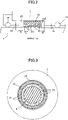
- Fig. 2 is an enlarged cross-sectional diagram illustrating a peripheral portion of the linear guide 20 including the linear guide 20
- Fig. 3 is a cross-sectional diagram (a cross-sectional diagram cut along a C-C arrow in Fig. 1 ) illustrating the linear guide 20 viewed from the front side.
- the needle valve 4 is advancingly or retractably fitted into the housing 1 in a forward or a backward direction.
- a space s1 is set between the needle valve 4 and an inner wall of the housing 1 so that the needle valve 4 can be moved in the axial direction, and the paint chamber 3 and the driving mechanism housing space 9 can be isolated by the O-rings 10 and 11.
- a space s2 is set between the linear guide 20 and the inner wall of the housing 1.
- the linear guide 20 is rotatably disposed with a plurality of rigid spheres 21 in an axial direction and in a circumferential direction, respectively.
- Each of the rigid spheres 21 is disposed to rotate smoothly with a grease, and the plurality of rigid spheres 21 is configured to rotate as the needle valve 4 moves in an axial direction while supporting a circumferential surface of the needle valve 4, thereby maintaining the rectlinearity of the needle valve 4. Since the linear guide 20 slides with respect to the needle valve 4 via the bearing, sparks are not generated. Accordingly, the paint discharging nozzle 100 is safe.
- the linear guide 20 is disposed in a cylindrical space 25 such that the linear guide 20 is movable in an axial direction within the cylindrical space 25.
- play (backlash) A + B in an axial direction within space 25 is configured to have a length of at least L ⁇ n, where L is the diameter of the rigid sphere 21.
- the linear guide 20 axially moves by the length of A + B to distribute the grease throughout the rigid spheres, thereby preventing a shortage of grease.
- a linear guide 20 (bearing) is disposed around the needle valve 4 to allow the linear guide 20 (bearing) to slide on the needle valve 4.
- the linear guide 20 is disposed within the space 25 in the housing 1, and an axial play (a backlash) equal to or longer than the circumference of a rigid sphere 21 is provided within the space 25 in the housing 1.
- This configuration enables the linear guide 20 to move by the weight of the linear guide 20 itself, thereby spreading the grease on all the rigid spheres 21, and preventing the grease from drying out. Further, since the gap between the needle valve 4 and the inner wall of the housing 1 is limited to a small amount, it is possible to prevent the vaporizing paint from flowing toward the driving mechanism side. This can prevent ignition in the paint chamber 3 when sparks are generated in the driving mechanism side.
- a member on which the needle valve 4 slides in the linear guide 20 is defined as a rigid sphere 21.
- the member is not limited thereto, but may be a roller, such as a disk or a cylinder, other than a sphere.
- the piezo-element 8 (driving mechanism) is connected to the rear end of the needle valve 4, but the present invention is not limited to this configuration.
- a drive pin 13 may have one end connected to the rear end of the needle valve 4, and may have the other end connected to a piezo-element 8 (driving mechanism). In such a configuration, damage is restricted merely to the drive pin 13 even if an explosion occurs in the driving mechanism, and damages to the needle valve 4 and to the paint chamber 3 can be prevented.
Landscapes
- Engineering & Computer Science (AREA)
- General Engineering & Computer Science (AREA)
- Mechanical Engineering (AREA)
- Coating Apparatus (AREA)
- Nozzles (AREA)
- Spray Control Apparatus (AREA)
Abstract
Description
- The disclosures discussed herein relate to a paint discharging nozzle.
- In the automobile manufacturing process, for example, when two colors of painting (called "2-tone painting") are applied to the surface of the automobile body, the paint is sprayed in the form of mist by a spray gun. Thus, the automobile body is masked and then the paint is sprayed to the masked surface of the automobile body by a spray gun to define a boundary line.
- However, the masking of the automobile body and removing the mask after painting is burdensome and the work efficiency is decreased.
In order to handle such drawbacks, attention has been attracted to a method of defining a boundary line without masking by using a paint discharging nozzle with a narrow spray width. -
Patent Document 1 discloses, for example, an application device having a paint discharging nozzle. The application (print) device disclosed inPatent Document 1 includes a head array (paint discharging nozzle head). The head array includes a plurality of paint discharging nozzles disposed in array to inject compressed air and apply high pressure to the ink tank filled with paint to discharge the paint to a remote area. - The application device further includes a linear rail for moving the head array back and forth in a linear manner, a multi-articulated robot for moving the linear rail by a robot arm, and a controller for controlling the driving of the robot and the paint discharging nozzle. In the head array, a plurality of nozzles arranged in a horizontal array discharges each paint color from each nozzle while moving (scanning) on the linear rail in the array direction.
- Such an application device discharges the paint from a plurality of nozzles arranged in a linear manner along the scan direction, so that a film with a desired thickness can be formed by a small amount of scanning operation, and an application operation can be performed at a highspeed application operation involving boundary lines without performing a masking process.
-
Patent Document 2 discloses, for example, the structure of a related art paint discharging nozzle.Fig. 6 is a cross-sectional diagram of a paint discharging nozzle disclosed inPatent Document 2. InFig. 6 , the paint discharging nozzle includes ahousing 51 provided with anozzle hole 52 in the front surface of thehousing 51, apaint chamber 53 for supplying paint to thenozzle hole 52, and aneedle valve 54 disposed in thepaint chamber 53 and having a tip end for closing or opening thenozzle hole 52. The paint discharging nozzle further includes, as a driving mechanism (piezoelectric element) of theneedle valve 54, amovable core 58 secured to a rear side of theneedle valve 54, afixed core 61 disposed at an opposite side of themovable core 58, asolenoid 62, and aspring member 60 disposed between themovable core 58 and thefixed core 61. - An
elastic diaphragm 57 is disposed in a drivingmechanism housing space 59 for housing the driving mechanism to enclose theneedle valve 54 in order to prevent the paint in thepaint chamber 53 from flowing outside, and pressure P is applied to the paint in thepaint chamber 53 through apaint input passage 55. A pressure P equivalent to the pressure applied to the paint through a pressurizedpassage 63 is applied to a gas or liquid in the drivingmechanism housing space 59 to prevent the pressurized paint from leaking between theelastic diaphragm 57 and theneedle valve 54. -
Fig. 6 illustrates theneedle valve 54 closing thenozzle hole 52. In this case, since no electric current is applied to thesolenoid 62, the action of thespring member 60 pushes forward themovable core 58 and thesubsequent needle valve 54, thereby closing thenozzle hole 52. By contrast, when electric current is applied to thesolenoid 62, themovable core 58 is adsorbed to the fixedcore 61, and theneedle valve 54 moves backward to open thenozzle hole 52. -
- [Patent Document 1]
Japanese Patent Application Laid-Open No. 2015-027636 - [Patent Document 2]
Japanese Patent Application Laid-Open No. 2004-142382 - However, when vaporizing paint floating in the air in an automobile painting line intrudes into the driving mechanism (piezoelectric element), and a spark is generated by friction from the driving mechanism, there may be a risk that the vaporized paint that intrudes into the driving mechanism would ignite and explode, thereby destroying the
elastic diaphragm 57 and causing fire to spread to thepaint chamber 53. - Extensive studies have been conducted on the assumption that the needle valve is fitted into the housing in a retractable manner. Accordingly, it is an object of the present invention to provide a paint discharging nozzle capable of preventing the paint chamber from being ignited from the driving mechanism.
- According to the present embodiment, a paint discharging nozzle includes:
- a housing having a nozzle hole through which paint is discharged;
- a paint chamber configured to supply paint to the nozzle hole;
- a needle valve retractably or advancingly fitted into the housing to close or open the nozzle hole;
- a driving mechanism disposed in the housing and configured to cause the needle valve to perform a retracting or advancing operation with respect to the nozzle hole; and
- a bearing disposed to surround the needle valve within the housing to be in sliding contact with a peripheral surface of the needle valve as the retracting or advancing operation of the needle valve is performed, wherein
- the bearing is movable in an axial direction of the needle valve.
- It should be noted that the distance at which the bearing can be moved axially of the needle valve is preferably at least a circumferential length of the bearing sphere or roller. Further, a drive pin having one end connected to the end of the needle valve on the driving mechanism side may be provided, and the other end of the drive pin may be connected to the driving mechanism.
- As described above, a bearing disposed around the needle valve slides on the needle valve to move the bearing in the axial direction. This configuration enables spreading of the grease on the balls or rollers of the bearing to prevent the grease from drying out. In addition, the gap between the needle valve and the inner wall of the housing can be limited to a small size. This configuration can prevent the inflow of vaporized paint into the driving mechanism, can prevent vaporized paint from flowing out of the driving mechanism, and can prevent ignition in the paint chamber upon a spark being generated in the driving mechanism.
- According to the present invention, it is possible to provide a paint discharging nozzle capable of preventing ignition generated from the driving mechanism to the paint chamber.
-
-
Fig. 1 is a block diagram schematically illustrating a main configuration of a paint discharging nozzle according to a present embodiment; -
Fig. 2 is a partially enlarged cross-sectional diagram of the periphery of the paint discharging nozzle inFig. 1 including a linear guide; -
Fig. 3 is a cross-sectional diagram (a cross-sectional diagram cut along a C-C arrow inFig. 1 ) illustrating the linear guide inFig. 2 viewed from the front side; -
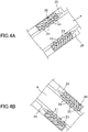
Figs. 4A and 4B are cross-sectional diagrams illustrating different states of the linear guide inFig. 2 ; -
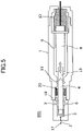
Fig. 5 is a cross-sectional diagram illustrating a modification of the paint discharging nozzle according to the present embodiment; and -
Fig. 6 is a cross-sectional diagram illustrating a configuration of a related art paint discharging nozzle. - Hereinafter, an embodiment of a paint discharging nozzle according to the present invention will be described with reference to the accompanying drawings. The paint discharging nozzle according to the present embodiment is used, for example, in an application device in an automobile manufacturing line, and is configured to discharge paint, such as 2 tone painting (having a boundary with the other color of painting).
-
Fig. 1 is a block diagram schematically illustrating a main configuration of a paint discharging nozzle according to the present embodiment. Thepaint discharging nozzle 100 includes ahousing 1 provided with anozzle hole 2, apaint chamber 3 configured to supply paint to thenozzle hole 2, aneedle valve 4 fitted into thehousing 1 such that theneedle valve 4 is able to retract or advance and configured to close or open thenozzle hole 2, and a piezo-element 8 as a driving mechanism connected to theneedle valve 4. - A
paint input passage 5 is connected to a side of thepaint chamber 3, and apaint collection passage 6 is connected to the opposite side of thepaint chamber 3. The paint is constantly supplied to thepaint chamber 3 from the paint supply unit (not illustrated) through thepaint input passage 5, and the paint supplied to thepaint chamber 3 is collected through thepaint collection passage 6. This configuration enables thepaint chamber 3 to be filled with paint without congestion of the paint. When thenozzle hole 2 is in the closed state, the predetermined pressure is maintained in thepaint chamber 3 by adjusting the rate at which the paint flows from thepaint input passage 5. - The piezo-
element 8 is configured to change an axial length of theneedle valve 4 to move theneedle valve 4 toward the nozzle hole 2 (advanced) and to close thenozzle hole 2 with the tip end of the needle valve 4 (the nozzle hole closed state), in response to a predetermined voltage or more being applied to the piezo-element 8 by a voltage applying unit (not illustrated). - By contrast, the piezo-
element 8 deforms in a direction in which theneedle valve 4 moves away from thenozzle hole 2 to move the tip end of theneedle valve 4 away from the nozzle hole 2 (the nozzle hole open state) in response to the applied voltage being lowered from the voltage in the nozzle hole closed state. When thenozzle hole 2 is opened,droplets 17 are discharged from thenozzle hole 2 toward a workpiece by the pressure inside thepaint chamber 3 as illustrated inFig. 1 . - The piezo-
element 8 is housed in a drivingmechanism housing space 9 formed inside thehousing 1, and aresin 12 is filled in the drivingmechanism housing space 9 at an end opposite to thenozzle hole 2 side in the axial direction of theneedle valve 4, thereby insulating the lead-in electric wire to the piezo-element 8. The drivingmechanism housing space 9 is separated from thepaint chamber 3 via double O-rings paint chamber 3 to flow out into the drivingmechanism housing space 9. - Further, as illustrated in the drawing, a
linear guide 20 made by a bearing is disposed around theneedle valve 4 in a radial direction between the O-rings Fig. 2 is an enlarged cross-sectional diagram illustrating a peripheral portion of thelinear guide 20 including thelinear guide 20, andFig. 3 is a cross-sectional diagram (a cross-sectional diagram cut along a C-C arrow inFig. 1 ) illustrating thelinear guide 20 viewed from the front side. As noted above, theneedle valve 4 is advancingly or retractably fitted into thehousing 1 in a forward or a backward direction. A space s1 is set between theneedle valve 4 and an inner wall of thehousing 1 so that theneedle valve 4 can be moved in the axial direction, and thepaint chamber 3 and the drivingmechanism housing space 9 can be isolated by the O-rings linear guide 20 and the inner wall of thehousing 1. - The
linear guide 20 is rotatably disposed with a plurality ofrigid spheres 21 in an axial direction and in a circumferential direction, respectively. Each of therigid spheres 21 is disposed to rotate smoothly with a grease, and the plurality ofrigid spheres 21 is configured to rotate as theneedle valve 4 moves in an axial direction while supporting a circumferential surface of theneedle valve 4, thereby maintaining the rectlinearity of theneedle valve 4. Since thelinear guide 20 slides with respect to theneedle valve 4 via the bearing, sparks are not generated. Accordingly, thepaint discharging nozzle 100 is safe. - The
linear guide 20 is disposed in acylindrical space 25 such that thelinear guide 20 is movable in an axial direction within thecylindrical space 25. As illustrated inFig. 2 , play (backlash) A + B in an axial direction withinspace 25 is configured to have a length of at least L × n, where L is the diameter of therigid sphere 21. In this manner, thelinear guide 20 axially moves by the length of A + B to distribute the grease throughout the rigid spheres, thereby preventing a shortage of grease. - When the
paint discharging nozzle 100 is used, thepaint discharging nozzle 100 is held at the tip end of a robot arm (not illustrated) to discharge the paint toward a workpiece. However, when the tip end of the nozzle is turned upward or downward at a time before and after discharge, thelinear guide 20 is moved axially by the weight of thelinear guide 20 itself within thespace 25 as illustrated inFigs. 4A and 4B . As a result, the grease can be easily distributed to all the rigid spheres. - As described above, according to the embodiment of the present invention, a linear guide 20 (bearing) is disposed around the
needle valve 4 to allow the linear guide 20 (bearing) to slide on theneedle valve 4. According to this configuration, it is possible to maintain the rectlinearity of theneedle valve 4, and improve the painting accuracy even if theneedle valve 4 is advancingly and retractably fitted into thehousing 1, that is, even if the distance between theneedle valve 4 and the inner wall of thehousing 1 is restricted to a small amount. In addition, thelinear guide 20 is disposed within thespace 25 in thehousing 1, and an axial play (a backlash) equal to or longer than the circumference of arigid sphere 21 is provided within thespace 25 in thehousing 1. This configuration enables thelinear guide 20 to move by the weight of thelinear guide 20 itself, thereby spreading the grease on all therigid spheres 21, and preventing the grease from drying out. Further, since the gap between theneedle valve 4 and the inner wall of thehousing 1 is limited to a small amount, it is possible to prevent the vaporizing paint from flowing toward the driving mechanism side. This can prevent ignition in thepaint chamber 3 when sparks are generated in the driving mechanism side. - According to the aforementioned embodiment, a member on which the
needle valve 4 slides in thelinear guide 20 is defined as arigid sphere 21. However, in the present invention, the member is not limited thereto, but may be a roller, such as a disk or a cylinder, other than a sphere. - According to the aforementioned embodiment, the piezo-element 8 (driving mechanism) is connected to the rear end of the
needle valve 4, but the present invention is not limited to this configuration. For example, as illustrated inFig. 5 , adrive pin 13 may have one end connected to the rear end of theneedle valve 4, and may have the other end connected to a piezo-element 8 (driving mechanism). In such a configuration, damage is restricted merely to thedrive pin 13 even if an explosion occurs in the driving mechanism, and damages to theneedle valve 4 and to thepaint chamber 3 can be prevented.
Claims (3)
- A paint discharging nozzle designed for discharging paint supplied at a predetermined pressure, the paint discharging nozzle comprising:a housing having a nozzle hole through which paint is discharged;a paint chamber configured to supply paint to the nozzle hole;a needle valve retractably or advancingly fitted into the housing to close or open the nozzle hole;a driving mechanism disposed in the housing and configured to cause the needle valve to perform a retracting or advancing operation with respect to the nozzle hole; anda bearing disposed to surround the needle valve within the housing to be in sliding contact with a peripheral surface of the needle valve as the retracting or advancing operation of the needle valve is performed, whereinthe bearing is movable in an axial direction of the needle valve.
- The paint discharging nozzle according to 1, wherein
a backlash, in a space within which the bearing is movable in the axial direction of the needle valve, has a length of at least a circumferential length of a sphere of the bearing or a roller. - The paint discharging nozzle according to claim 1 or claim 2, further comprising:a drive pin having one end connected to a tip end of the needle valve on the driving mechanism side, whereinthe other end of the drive pin is connected to the driving mechanism.
Applications Claiming Priority (1)
| Application Number | Priority Date | Filing Date | Title |
|---|---|---|---|
| JP2020173141A JP7553316B2 (en) | 2020-10-14 | 2020-10-14 | Paint injection nozzle |
Publications (2)
| Publication Number | Publication Date |
|---|---|
| EP3984650A1 true EP3984650A1 (en) | 2022-04-20 |
| EP3984650B1 EP3984650B1 (en) | 2024-05-29 |
Family
ID=78087214
Family Applications (1)
| Application Number | Title | Priority Date | Filing Date |
|---|---|---|---|
| EP21201987.1A Active EP3984650B1 (en) | 2020-10-14 | 2021-10-11 | Paint discharging nozzle |
Country Status (3)
| Country | Link |
|---|---|
| US (1) | US12030066B2 (en) |
| EP (1) | EP3984650B1 (en) |
| JP (1) | JP7553316B2 (en) |
Families Citing this family (2)
| Publication number | Priority date | Publication date | Assignee | Title |
|---|---|---|---|---|
| JP7825466B2 (en) | 2022-03-11 | 2026-03-06 | 株式会社リコー | Liquid ejection head and liquid ejection device |
| JP2024130575A (en) | 2023-03-15 | 2024-09-30 | 株式会社リコー | Liquid ejection head and liquid ejection device |
Citations (7)
| Publication number | Priority date | Publication date | Assignee | Title |
|---|---|---|---|---|
| GB2014795A (en) * | 1978-02-20 | 1979-08-30 | Jidosha Kiki Co | Electro-mechanical converters and control apparatus for power steering units utilizing the same |
| US5945160A (en) * | 1991-03-08 | 1999-08-31 | Preferred Machining Corporation | Fluid dispensing system |
| US6170767B1 (en) * | 1997-12-17 | 2001-01-09 | Robert Bosch Gmbh | Fuel injection valve |
| JP2004142382A (en) | 2002-10-28 | 2004-05-20 | Lac:Kk | Ink jet nozzle |
| WO2013089918A1 (en) * | 2011-12-15 | 2013-06-20 | Graco Minnesota Inc. | Internal valve tip filter |
| JP2015027636A (en) | 2013-07-04 | 2015-02-12 | 株式会社エルエーシー | Printing apparatus |
| JP2019056419A (en) * | 2017-09-21 | 2019-04-11 | 日本電産トーソク株式会社 | solenoid valve |
Family Cites Families (17)
| Publication number | Priority date | Publication date | Assignee | Title |
|---|---|---|---|---|
| JPS6010912B2 (en) | 1978-10-04 | 1985-03-20 | キヤノン株式会社 | recording head |
| JPS58102774A (en) | 1981-12-14 | 1983-06-18 | Nec Corp | Ink jet recording method and its device |
| JPH0741185B2 (en) * | 1986-02-12 | 1995-05-10 | ソニー株式会社 | Viscous substance coating device |
| US5236264A (en) * | 1991-06-10 | 1993-08-17 | Nsk Ltd. | Linear bearing |
| DE19726382A1 (en) * | 1997-06-21 | 1998-12-24 | Bosch Gmbh Robert | Fuel injection valve for IC engines with valve housing having opening extending longitudinally |
| DE60006659T2 (en) | 1999-04-19 | 2004-10-07 | Nordson Corp | METHOD FOR DISPENSING VISCOSIC LIQUIDS |
| US8820871B2 (en) | 2010-10-27 | 2014-09-02 | Matthews Resources, Inc. | Valve jet printer with inert plunger tip |
| JP5914064B2 (en) | 2012-03-12 | 2016-05-11 | 株式会社エルエーシー | Printing device |
| JP6079301B2 (en) | 2013-02-28 | 2017-02-15 | 株式会社リコー | Image forming apparatus and head drive control method |
| JP6630281B2 (en) * | 2014-02-14 | 2020-01-15 | ノードソン コーポレーションNordson Corporation | Jetting dispenser and method for jetting droplets of fluid material |
| JP6842152B2 (en) | 2016-05-31 | 2021-03-17 | 武蔵エンジニアリング株式会社 | Liquid material discharge device, its coating device and coating method |
| JP6834765B2 (en) | 2017-05-16 | 2021-02-24 | 株式会社リコー | Inkjet printer and 3D printing method |
| JP7271956B2 (en) | 2018-01-16 | 2023-05-12 | 株式会社リコー | Device for ejecting valve type nozzle and liquid |
| JP2019150798A (en) | 2018-03-06 | 2019-09-12 | パナソニックIpマネジメント株式会社 | Coating method and device of liquid material |
| US11148364B2 (en) | 2018-07-19 | 2021-10-19 | Ricoh Company, Ltd. | Three dimensional modeling apparatus |
| EP3599102B1 (en) | 2018-07-24 | 2022-11-09 | Ricoh Company, Ltd. | Liquid jet device |
| US10987927B2 (en) | 2018-08-01 | 2021-04-27 | Ricoh Company, Ltd. | Liquid discharge head, head unit, apparatus for discharging liquid, and liquid discharging method |
-
2020
- 2020-10-14 JP JP2020173141A patent/JP7553316B2/en active Active
-
2021
- 2021-10-11 EP EP21201987.1A patent/EP3984650B1/en active Active
- 2021-10-12 US US17/498,848 patent/US12030066B2/en active Active
Patent Citations (7)
| Publication number | Priority date | Publication date | Assignee | Title |
|---|---|---|---|---|
| GB2014795A (en) * | 1978-02-20 | 1979-08-30 | Jidosha Kiki Co | Electro-mechanical converters and control apparatus for power steering units utilizing the same |
| US5945160A (en) * | 1991-03-08 | 1999-08-31 | Preferred Machining Corporation | Fluid dispensing system |
| US6170767B1 (en) * | 1997-12-17 | 2001-01-09 | Robert Bosch Gmbh | Fuel injection valve |
| JP2004142382A (en) | 2002-10-28 | 2004-05-20 | Lac:Kk | Ink jet nozzle |
| WO2013089918A1 (en) * | 2011-12-15 | 2013-06-20 | Graco Minnesota Inc. | Internal valve tip filter |
| JP2015027636A (en) | 2013-07-04 | 2015-02-12 | 株式会社エルエーシー | Printing apparatus |
| JP2019056419A (en) * | 2017-09-21 | 2019-04-11 | 日本電産トーソク株式会社 | solenoid valve |
Also Published As
| Publication number | Publication date |
|---|---|
| JP7553316B2 (en) | 2024-09-18 |
| US20220111406A1 (en) | 2022-04-14 |
| US12030066B2 (en) | 2024-07-09 |
| EP3984650B1 (en) | 2024-05-29 |
| JP2022064483A (en) | 2022-04-26 |
Similar Documents
| Publication | Publication Date | Title |
|---|---|---|
| EP3984650B1 (en) | Paint discharging nozzle | |
| US4241880A (en) | Electrostatic spray gun | |
| JPH0239312B2 (en) | ||
| US3843052A (en) | Pneumatically assisted hydraulic spray coating apparatus | |
| KR900002900A (en) | Portable power tools | |
| EP4108344B1 (en) | Electrostatic coating device | |
| JP2022064482A (en) | Coating material spray nozzle and control method of the same | |
| DE1646027A1 (en) | Nozzle and gas mixing arrangement for a powder flame spray gun | |
| WO2008037514A1 (en) | Rotating wire spraying device and a method for coating a surface of a workpiece | |
| US6425533B1 (en) | Spray gun with common control of fluid and air valve | |
| GB1469134A (en) | Automatic painting guns | |
| EP0235263B1 (en) | Process and apparatus for high pressure impact coating | |
| KR20140132107A (en) | Pressure regulator-integrated spray gun | |
| DE2209896A1 (en) | Atomizer | |
| JP3242584U (en) | paint spray gun | |
| DE69718845T2 (en) | Arc suppression device for supply systems for electrically conductive coating materials | |
| JPH07171446A (en) | Internal mixing type spray gun | |
| EP1427560A1 (en) | Air feed weld gun with retractable piston | |
| US4779559A (en) | Apparatus for high pressure impact coating | |
| JPH0487654A (en) | Spraying device and controller for the device | |
| DE3833279A1 (en) | FUEL NOZZLE FOR GAS TURBINES | |
| JP2002059034A (en) | Electrostatic painting gun | |
| DE1652456A1 (en) | High performance electrostatic liquid spray gun | |
| JP2016077999A (en) | Electrostatic coating machine | |
| CN121653639A (en) | Laser cladding robot for inner wall of cylinder barrel of hydraulic actuator of airplane |
Legal Events
| Date | Code | Title | Description |
|---|---|---|---|
| PUAI | Public reference made under article 153(3) epc to a published international application that has entered the european phase |
Free format text: ORIGINAL CODE: 0009012 |
|
| STAA | Information on the status of an ep patent application or granted ep patent |
Free format text: STATUS: REQUEST FOR EXAMINATION WAS MADE |
|
| 17P | Request for examination filed |
Effective date: 20211011 |
|
| AK | Designated contracting states |
Kind code of ref document: A1 Designated state(s): AL AT BE BG CH CY CZ DE DK EE ES FI FR GB GR HR HU IE IS IT LI LT LU LV MC MK MT NL NO PL PT RO RS SE SI SK SM TR |
|
| STAA | Information on the status of an ep patent application or granted ep patent |
Free format text: STATUS: EXAMINATION IS IN PROGRESS |
|
| 17Q | First examination report despatched |
Effective date: 20230612 |
|
| GRAP | Despatch of communication of intention to grant a patent |
Free format text: ORIGINAL CODE: EPIDOSNIGR1 |
|
| STAA | Information on the status of an ep patent application or granted ep patent |
Free format text: STATUS: GRANT OF PATENT IS INTENDED |
|
| RIC1 | Information provided on ipc code assigned before grant |
Ipc: B05B 15/58 20180101ALN20240122BHEP Ipc: F16C 29/04 20060101ALN20240122BHEP Ipc: F16C 33/66 20060101ALI20240122BHEP Ipc: B05C 11/10 20060101ALI20240122BHEP Ipc: B05C 5/02 20060101ALI20240122BHEP Ipc: B05B 1/30 20060101AFI20240122BHEP |
|
| RIC1 | Information provided on ipc code assigned before grant |
Ipc: B05B 15/58 20180101ALN20240129BHEP Ipc: F16C 29/04 20060101ALN20240129BHEP Ipc: F16C 33/66 20060101ALI20240129BHEP Ipc: B05C 11/10 20060101ALI20240129BHEP Ipc: B05C 5/02 20060101ALI20240129BHEP Ipc: B05B 1/30 20060101AFI20240129BHEP |
|
| INTG | Intention to grant announced |
Effective date: 20240215 |
|
| RIC1 | Information provided on ipc code assigned before grant |
Ipc: B05B 15/58 20180101ALN20240205BHEP Ipc: F16C 29/04 20060101ALN20240205BHEP Ipc: F16C 33/66 20060101ALI20240205BHEP Ipc: B05C 11/10 20060101ALI20240205BHEP Ipc: B05C 5/02 20060101ALI20240205BHEP Ipc: B05B 1/30 20060101AFI20240205BHEP |
|
| GRAS | Grant fee paid |
Free format text: ORIGINAL CODE: EPIDOSNIGR3 |
|
| GRAA | (expected) grant |
Free format text: ORIGINAL CODE: 0009210 |
|
| STAA | Information on the status of an ep patent application or granted ep patent |
Free format text: STATUS: THE PATENT HAS BEEN GRANTED |
|
| P01 | Opt-out of the competence of the unified patent court (upc) registered |
Effective date: 20240402 |
|
| AK | Designated contracting states |
Kind code of ref document: B1 Designated state(s): AL AT BE BG CH CY CZ DE DK EE ES FI FR GB GR HR HU IE IS IT LI LT LU LV MC MK MT NL NO PL PT RO RS SE SI SK SM TR |
|
| REG | Reference to a national code |
Ref country code: CH Ref legal event code: EP |
|
| REG | Reference to a national code |
Ref country code: IE Ref legal event code: FG4D |
|
| REG | Reference to a national code |
Ref country code: DE Ref legal event code: R096 Ref document number: 602021013773 Country of ref document: DE |
|
| REG | Reference to a national code |
Ref country code: LT Ref legal event code: MG9D |
|
| REG | Reference to a national code |
Ref country code: NL Ref legal event code: MP Effective date: 20240529 |
|
| PG25 | Lapsed in a contracting state [announced via postgrant information from national office to epo] |
Ref country code: IS Free format text: LAPSE BECAUSE OF FAILURE TO SUBMIT A TRANSLATION OF THE DESCRIPTION OR TO PAY THE FEE WITHIN THE PRESCRIBED TIME-LIMIT Effective date: 20240929 |
|
| PG25 | Lapsed in a contracting state [announced via postgrant information from national office to epo] |
Ref country code: BG Free format text: LAPSE BECAUSE OF FAILURE TO SUBMIT A TRANSLATION OF THE DESCRIPTION OR TO PAY THE FEE WITHIN THE PRESCRIBED TIME-LIMIT Effective date: 20240529 |
|
| PG25 | Lapsed in a contracting state [announced via postgrant information from national office to epo] |
Ref country code: HR Free format text: LAPSE BECAUSE OF FAILURE TO SUBMIT A TRANSLATION OF THE DESCRIPTION OR TO PAY THE FEE WITHIN THE PRESCRIBED TIME-LIMIT Effective date: 20240529 Ref country code: FI Free format text: LAPSE BECAUSE OF FAILURE TO SUBMIT A TRANSLATION OF THE DESCRIPTION OR TO PAY THE FEE WITHIN THE PRESCRIBED TIME-LIMIT Effective date: 20240529 |
|
| PG25 | Lapsed in a contracting state [announced via postgrant information from national office to epo] |
Ref country code: GR Free format text: LAPSE BECAUSE OF FAILURE TO SUBMIT A TRANSLATION OF THE DESCRIPTION OR TO PAY THE FEE WITHIN THE PRESCRIBED TIME-LIMIT Effective date: 20240830 |
|
| REG | Reference to a national code |
Ref country code: AT Ref legal event code: MK05 Ref document number: 1690192 Country of ref document: AT Kind code of ref document: T Effective date: 20240529 |
|
| PG25 | Lapsed in a contracting state [announced via postgrant information from national office to epo] |
Ref country code: ES Free format text: LAPSE BECAUSE OF FAILURE TO SUBMIT A TRANSLATION OF THE DESCRIPTION OR TO PAY THE FEE WITHIN THE PRESCRIBED TIME-LIMIT Effective date: 20240529 |
|
| PG25 | Lapsed in a contracting state [announced via postgrant information from national office to epo] |
Ref country code: AT Free format text: LAPSE BECAUSE OF FAILURE TO SUBMIT A TRANSLATION OF THE DESCRIPTION OR TO PAY THE FEE WITHIN THE PRESCRIBED TIME-LIMIT Effective date: 20240529 |
|
| PG25 | Lapsed in a contracting state [announced via postgrant information from national office to epo] |
Ref country code: PL Free format text: LAPSE BECAUSE OF FAILURE TO SUBMIT A TRANSLATION OF THE DESCRIPTION OR TO PAY THE FEE WITHIN THE PRESCRIBED TIME-LIMIT Effective date: 20240529 |
|
| PG25 | Lapsed in a contracting state [announced via postgrant information from national office to epo] |
Ref country code: LV Free format text: LAPSE BECAUSE OF FAILURE TO SUBMIT A TRANSLATION OF THE DESCRIPTION OR TO PAY THE FEE WITHIN THE PRESCRIBED TIME-LIMIT Effective date: 20240529 |
|
| PG25 | Lapsed in a contracting state [announced via postgrant information from national office to epo] |
Ref country code: PL Free format text: LAPSE BECAUSE OF FAILURE TO SUBMIT A TRANSLATION OF THE DESCRIPTION OR TO PAY THE FEE WITHIN THE PRESCRIBED TIME-LIMIT Effective date: 20240529 Ref country code: NO Free format text: LAPSE BECAUSE OF FAILURE TO SUBMIT A TRANSLATION OF THE DESCRIPTION OR TO PAY THE FEE WITHIN THE PRESCRIBED TIME-LIMIT Effective date: 20240829 Ref country code: LV Free format text: LAPSE BECAUSE OF FAILURE TO SUBMIT A TRANSLATION OF THE DESCRIPTION OR TO PAY THE FEE WITHIN THE PRESCRIBED TIME-LIMIT Effective date: 20240529 Ref country code: IS Free format text: LAPSE BECAUSE OF FAILURE TO SUBMIT A TRANSLATION OF THE DESCRIPTION OR TO PAY THE FEE WITHIN THE PRESCRIBED TIME-LIMIT Effective date: 20240929 Ref country code: HR Free format text: LAPSE BECAUSE OF FAILURE TO SUBMIT A TRANSLATION OF THE DESCRIPTION OR TO PAY THE FEE WITHIN THE PRESCRIBED TIME-LIMIT Effective date: 20240529 Ref country code: GR Free format text: LAPSE BECAUSE OF FAILURE TO SUBMIT A TRANSLATION OF THE DESCRIPTION OR TO PAY THE FEE WITHIN THE PRESCRIBED TIME-LIMIT Effective date: 20240830 Ref country code: FI Free format text: LAPSE BECAUSE OF FAILURE TO SUBMIT A TRANSLATION OF THE DESCRIPTION OR TO PAY THE FEE WITHIN THE PRESCRIBED TIME-LIMIT Effective date: 20240529 Ref country code: ES Free format text: LAPSE BECAUSE OF FAILURE TO SUBMIT A TRANSLATION OF THE DESCRIPTION OR TO PAY THE FEE WITHIN THE PRESCRIBED TIME-LIMIT Effective date: 20240529 Ref country code: BG Free format text: LAPSE BECAUSE OF FAILURE TO SUBMIT A TRANSLATION OF THE DESCRIPTION OR TO PAY THE FEE WITHIN THE PRESCRIBED TIME-LIMIT Effective date: 20240529 Ref country code: AT Free format text: LAPSE BECAUSE OF FAILURE TO SUBMIT A TRANSLATION OF THE DESCRIPTION OR TO PAY THE FEE WITHIN THE PRESCRIBED TIME-LIMIT Effective date: 20240529 Ref country code: RS Free format text: LAPSE BECAUSE OF FAILURE TO SUBMIT A TRANSLATION OF THE DESCRIPTION OR TO PAY THE FEE WITHIN THE PRESCRIBED TIME-LIMIT Effective date: 20240829 |
|
| PG25 | Lapsed in a contracting state [announced via postgrant information from national office to epo] |
Ref country code: NL Free format text: LAPSE BECAUSE OF FAILURE TO SUBMIT A TRANSLATION OF THE DESCRIPTION OR TO PAY THE FEE WITHIN THE PRESCRIBED TIME-LIMIT Effective date: 20240529 |
|
| PG25 | Lapsed in a contracting state [announced via postgrant information from national office to epo] |
Ref country code: NL Free format text: LAPSE BECAUSE OF FAILURE TO SUBMIT A TRANSLATION OF THE DESCRIPTION OR TO PAY THE FEE WITHIN THE PRESCRIBED TIME-LIMIT Effective date: 20240529 |
|
| PG25 | Lapsed in a contracting state [announced via postgrant information from national office to epo] |
Ref country code: DK Free format text: LAPSE BECAUSE OF FAILURE TO SUBMIT A TRANSLATION OF THE DESCRIPTION OR TO PAY THE FEE WITHIN THE PRESCRIBED TIME-LIMIT Effective date: 20240529 |
|
| PG25 | Lapsed in a contracting state [announced via postgrant information from national office to epo] |
Ref country code: EE Free format text: LAPSE BECAUSE OF FAILURE TO SUBMIT A TRANSLATION OF THE DESCRIPTION OR TO PAY THE FEE WITHIN THE PRESCRIBED TIME-LIMIT Effective date: 20240529 |
|
| PG25 | Lapsed in a contracting state [announced via postgrant information from national office to epo] |
Ref country code: CZ Free format text: LAPSE BECAUSE OF FAILURE TO SUBMIT A TRANSLATION OF THE DESCRIPTION OR TO PAY THE FEE WITHIN THE PRESCRIBED TIME-LIMIT Effective date: 20240529 |
|
| PG25 | Lapsed in a contracting state [announced via postgrant information from national office to epo] |
Ref country code: SK Free format text: LAPSE BECAUSE OF FAILURE TO SUBMIT A TRANSLATION OF THE DESCRIPTION OR TO PAY THE FEE WITHIN THE PRESCRIBED TIME-LIMIT Effective date: 20240529 Ref country code: RO Free format text: LAPSE BECAUSE OF FAILURE TO SUBMIT A TRANSLATION OF THE DESCRIPTION OR TO PAY THE FEE WITHIN THE PRESCRIBED TIME-LIMIT Effective date: 20240529 |
|
| PG25 | Lapsed in a contracting state [announced via postgrant information from national office to epo] |
Ref country code: SM Free format text: LAPSE BECAUSE OF FAILURE TO SUBMIT A TRANSLATION OF THE DESCRIPTION OR TO PAY THE FEE WITHIN THE PRESCRIBED TIME-LIMIT Effective date: 20240529 |
|
| PG25 | Lapsed in a contracting state [announced via postgrant information from national office to epo] |
Ref country code: SM Free format text: LAPSE BECAUSE OF FAILURE TO SUBMIT A TRANSLATION OF THE DESCRIPTION OR TO PAY THE FEE WITHIN THE PRESCRIBED TIME-LIMIT Effective date: 20240529 Ref country code: SK Free format text: LAPSE BECAUSE OF FAILURE TO SUBMIT A TRANSLATION OF THE DESCRIPTION OR TO PAY THE FEE WITHIN THE PRESCRIBED TIME-LIMIT Effective date: 20240529 Ref country code: RO Free format text: LAPSE BECAUSE OF FAILURE TO SUBMIT A TRANSLATION OF THE DESCRIPTION OR TO PAY THE FEE WITHIN THE PRESCRIBED TIME-LIMIT Effective date: 20240529 Ref country code: EE Free format text: LAPSE BECAUSE OF FAILURE TO SUBMIT A TRANSLATION OF THE DESCRIPTION OR TO PAY THE FEE WITHIN THE PRESCRIBED TIME-LIMIT Effective date: 20240529 Ref country code: DK Free format text: LAPSE BECAUSE OF FAILURE TO SUBMIT A TRANSLATION OF THE DESCRIPTION OR TO PAY THE FEE WITHIN THE PRESCRIBED TIME-LIMIT Effective date: 20240529 Ref country code: CZ Free format text: LAPSE BECAUSE OF FAILURE TO SUBMIT A TRANSLATION OF THE DESCRIPTION OR TO PAY THE FEE WITHIN THE PRESCRIBED TIME-LIMIT Effective date: 20240529 |
|
| PG25 | Lapsed in a contracting state [announced via postgrant information from national office to epo] |
Ref country code: IT Free format text: LAPSE BECAUSE OF FAILURE TO SUBMIT A TRANSLATION OF THE DESCRIPTION OR TO PAY THE FEE WITHIN THE PRESCRIBED TIME-LIMIT Effective date: 20240529 |
|
| REG | Reference to a national code |
Ref country code: DE Ref legal event code: R097 Ref document number: 602021013773 Country of ref document: DE |
|
| PLBE | No opposition filed within time limit |
Free format text: ORIGINAL CODE: 0009261 |
|
| STAA | Information on the status of an ep patent application or granted ep patent |
Free format text: STATUS: NO OPPOSITION FILED WITHIN TIME LIMIT |
|
| PG25 | Lapsed in a contracting state [announced via postgrant information from national office to epo] |
Ref country code: SI Free format text: LAPSE BECAUSE OF FAILURE TO SUBMIT A TRANSLATION OF THE DESCRIPTION OR TO PAY THE FEE WITHIN THE PRESCRIBED TIME-LIMIT Effective date: 20240529 |
|
| 26N | No opposition filed |
Effective date: 20250303 |
|
| REG | Reference to a national code |
Ref country code: CH Ref legal event code: PL |
|
| PG25 | Lapsed in a contracting state [announced via postgrant information from national office to epo] |
Ref country code: MC Free format text: LAPSE BECAUSE OF FAILURE TO SUBMIT A TRANSLATION OF THE DESCRIPTION OR TO PAY THE FEE WITHIN THE PRESCRIBED TIME-LIMIT Effective date: 20240529 |
|
| PG25 | Lapsed in a contracting state [announced via postgrant information from national office to epo] |
Ref country code: BE Free format text: LAPSE BECAUSE OF NON-PAYMENT OF DUE FEES Effective date: 20241031 Ref country code: LU Free format text: LAPSE BECAUSE OF NON-PAYMENT OF DUE FEES Effective date: 20241011 |
|
| PG25 | Lapsed in a contracting state [announced via postgrant information from national office to epo] |
Ref country code: CH Free format text: LAPSE BECAUSE OF NON-PAYMENT OF DUE FEES Effective date: 20241031 |
|
| REG | Reference to a national code |
Ref country code: BE Ref legal event code: MM Effective date: 20241031 |
|
| PG25 | Lapsed in a contracting state [announced via postgrant information from national office to epo] |
Ref country code: SE Free format text: LAPSE BECAUSE OF FAILURE TO SUBMIT A TRANSLATION OF THE DESCRIPTION OR TO PAY THE FEE WITHIN THE PRESCRIBED TIME-LIMIT Effective date: 20240529 |
|
| PG25 | Lapsed in a contracting state [announced via postgrant information from national office to epo] |
Ref country code: IE Free format text: LAPSE BECAUSE OF NON-PAYMENT OF DUE FEES Effective date: 20241011 |
|
| PGFP | Annual fee paid to national office [announced via postgrant information from national office to epo] |
Ref country code: DE Payment date: 20251021 Year of fee payment: 5 |
|
| PGFP | Annual fee paid to national office [announced via postgrant information from national office to epo] |
Ref country code: GB Payment date: 20251022 Year of fee payment: 5 |
|
| PGFP | Annual fee paid to national office [announced via postgrant information from national office to epo] |
Ref country code: FR Payment date: 20251030 Year of fee payment: 5 |
|
| PG25 | Lapsed in a contracting state [announced via postgrant information from national office to epo] |
Ref country code: CY Free format text: LAPSE BECAUSE OF FAILURE TO SUBMIT A TRANSLATION OF THE DESCRIPTION OR TO PAY THE FEE WITHIN THE PRESCRIBED TIME-LIMIT; INVALID AB INITIO Effective date: 20211011 |
|
| PG25 | Lapsed in a contracting state [announced via postgrant information from national office to epo] |
Ref country code: HU Free format text: LAPSE BECAUSE OF FAILURE TO SUBMIT A TRANSLATION OF THE DESCRIPTION OR TO PAY THE FEE WITHIN THE PRESCRIBED TIME-LIMIT; INVALID AB INITIO Effective date: 20211011 |