EP3984600A1 - Dispositif de frein - Google Patents
Dispositif de frein Download PDFInfo
- Publication number
- EP3984600A1 EP3984600A1 EP20827907.5A EP20827907A EP3984600A1 EP 3984600 A1 EP3984600 A1 EP 3984600A1 EP 20827907 A EP20827907 A EP 20827907A EP 3984600 A1 EP3984600 A1 EP 3984600A1
- Authority
- EP
- European Patent Office
- Prior art keywords
- rope
- braking device
- friction member
- members
- friction
- Prior art date
- Legal status (The legal status is an assumption and is not a legal conclusion. Google has not performed a legal analysis and makes no representation as to the accuracy of the status listed.)
- Pending
Links
- 230000007246 mechanism Effects 0.000 claims description 31
- 230000000149 penetrating effect Effects 0.000 claims description 9
- 230000008878 coupling Effects 0.000 claims description 8
- 238000010168 coupling process Methods 0.000 claims description 8
- 238000005859 coupling reaction Methods 0.000 claims description 8
- 238000009941 weaving Methods 0.000 claims description 2
- 229910052751 metal Inorganic materials 0.000 abstract description 9
- 239000002184 metal Substances 0.000 abstract description 9
- 239000011347 resin Substances 0.000 abstract description 8
- 229920005989 resin Polymers 0.000 abstract description 8
- 239000000463 material Substances 0.000 description 5
- 239000000203 mixture Substances 0.000 description 4
- 229920000728 polyester Polymers 0.000 description 4
- 239000000919 ceramic Substances 0.000 description 3
- 239000004677 Nylon Substances 0.000 description 2
- 229920000122 acrylonitrile butadiene styrene Polymers 0.000 description 2
- 229920001778 nylon Polymers 0.000 description 2
- 238000009987 spinning Methods 0.000 description 2
- 241001503987 Clematis vitalba Species 0.000 description 1
- 229920000271 Kevlar® Polymers 0.000 description 1
- 229920001494 Technora Polymers 0.000 description 1
- RTAQQCXQSZGOHL-UHFFFAOYSA-N Titanium Chemical compound [Ti] RTAQQCXQSZGOHL-UHFFFAOYSA-N 0.000 description 1
- 241000276425 Xiphophorus maculatus Species 0.000 description 1
- 229910052782 aluminium Inorganic materials 0.000 description 1
- XAGFODPZIPBFFR-UHFFFAOYSA-N aluminium Chemical compound [Al] XAGFODPZIPBFFR-UHFFFAOYSA-N 0.000 description 1
- 230000009194 climbing Effects 0.000 description 1
- 230000006835 compression Effects 0.000 description 1
- 238000007906 compression Methods 0.000 description 1
- 230000003247 decreasing effect Effects 0.000 description 1
- 230000001419 dependent effect Effects 0.000 description 1
- 239000000835 fiber Substances 0.000 description 1
- 239000003779 heat-resistant material Substances 0.000 description 1
- 239000004761 kevlar Substances 0.000 description 1
- 238000004519 manufacturing process Methods 0.000 description 1
- 238000000034 method Methods 0.000 description 1
- 238000000465 moulding Methods 0.000 description 1
- 239000000843 powder Substances 0.000 description 1
- -1 stainless Inorganic materials 0.000 description 1
- 239000004950 technora Substances 0.000 description 1
- 239000010936 titanium Substances 0.000 description 1
- 229910052719 titanium Inorganic materials 0.000 description 1
- 230000001960 triggered effect Effects 0.000 description 1
Images


Classifications
-
- F—MECHANICAL ENGINEERING; LIGHTING; HEATING; WEAPONS; BLASTING
- F16—ENGINEERING ELEMENTS AND UNITS; GENERAL MEASURES FOR PRODUCING AND MAINTAINING EFFECTIVE FUNCTIONING OF MACHINES OR INSTALLATIONS; THERMAL INSULATION IN GENERAL
- F16D—COUPLINGS FOR TRANSMITTING ROTATION; CLUTCHES; BRAKES
- F16D63/00—Brakes not otherwise provided for; Brakes combining more than one of the types of groups F16D49/00 - F16D61/00
- F16D63/008—Brakes acting on a linearly moving member
-
- A—HUMAN NECESSITIES
- A62—LIFE-SAVING; FIRE-FIGHTING
- A62B—DEVICES, APPARATUS OR METHODS FOR LIFE-SAVING
- A62B1/00—Devices for lowering persons from buildings or the like
- A62B1/06—Devices for lowering persons from buildings or the like by making use of rope-lowering devices
- A62B1/14—Devices for lowering persons from buildings or the like by making use of rope-lowering devices with brakes sliding on the rope
-
- A—HUMAN NECESSITIES
- A63—SPORTS; GAMES; AMUSEMENTS
- A63B—APPARATUS FOR PHYSICAL TRAINING, GYMNASTICS, SWIMMING, CLIMBING, OR FENCING; BALL GAMES; TRAINING EQUIPMENT
- A63B29/00—Apparatus for mountaineering
- A63B29/02—Mountain guy-ropes or accessories, e.g. avalanche ropes; Means for indicating the location of accidentally buried, e.g. snow-buried, persons
Definitions
- the present invention generally relates to a braking device for a rope.
- An ascender which supports climbing as disclosed in, for example, U.S. Pat. No. 8,225,905 is known as braking device for a rope.
- the present invention aims to provide techniques for effectively braking a rope.
- the subject matter of the present invention for solving the above-stated problem is a braking device comprising a friction member surrounding a rope and a hook for applying tension to the friction member in a longitudinal direction of the rope.
- the friction member is actuated to contact the rope when tension is applied.
- the friction member has elasticity in the longitudinal direction of the rope, being formed of, for example, resin or metal.
- the present invention enables effective braking of a rope.
- a braking device according to the embodiments of the present invention is provided as follows.
- a braking device 1 of the first embodiment is a descender for controlling slide of a rope by friction, used for the purpose of supporting descent with a rope.
- the braking device 1 of the present embodiment can also be used as an ascender.
- FIG 10 illustrates an exemplary structure of a conventional braking device 9.
- the conventional braking device 9 comprises a body 91 and a swivel part 92, allowing a rope 2 to pass between them.
- a hole part 94 on the swivel part 92 which is on the side opposite to the rope 2
- the swivel part 92 swivels around a pivot 93 to actuate the end 95 to clamp the rope, holding the rope 2 between the end 95 and an inner guiding wall 96 of the body 91 to stop the slide of the rope 2.
- a plurality of grooves 97 are formed on the end 95 to increase the friction between the end 95 and the rope 2.
- the rope 2 is held between the end 95 of the swivel part 92 and the inner guiding wall 96 where the uneven end 95 presses the rope 2, making the rope 2 subject to locally concentrated stress which can cause damage on the surface of the rope 2.
- the present disclosure provides a braking device 1 which generates friction so that stress is given to the rope 2 from more than three directions, preferably from at least four directions, and more preferably from all directions around the rope 2, rather than holding from two directions.
- FIG. 1 illustrates a braking device 1 according to the first embodiment.
- the braking device 1 is expected to be used as a descender.
- the braking device 1 according to the first embodiment comprises a body 11 configured of a spring.
- An inner diameter of the body 11 is set to a size allowing a rope 2 to pass therethrough, preferably a size allowing the rope 2 to slide while the inner surface of the body 11 abuts on the surface of the rope 2.
- a hook 15 is provided at the lower end 13 of the body 11, and is coupled to a climber's body. By pulling down (moving in the DN direction shown in the Figure 1 ) the lower end 13 for descending, the inner diameter of the body 11 shrinks, friction is increased, and then the body 11 starts descending with an appropriate slide.
- the inner diameter of the body 11 is expanded and the rope 2 is enabled to slide, for example, when a user pulls up a rope (not shown) coupled to the hook 15 in the UP direction of the Figure 1 or lifts the hook 15 or the lower end 13 up by hand in the UP direction.
- the user is able to ascend utilizing this mechanism.
- Figure 2 illustrates a braking device 1 in contracted and extended states.
- Figure 2(b) shows a braking device 1 in a state where the lower end 13 of the body 11 of the braking device 1 shown in Figure 2(a) is pulled down.
- the longitudinal length of the body 11 shown as L2 in Figure 2(b) is longer than the longitudinal length of the body 11 shown as L1 in Figure 2(a)
- the inner diameter of the body 11 shown as W2 in Figure 2(b) is smaller than the inner diameter of the body 11 shown as W1 in Figure 2(a) .
- the body 11 can apply inward force F in the radial direction approximately uniformly on all around the rope 2. Therefore, compared to the conventional braking device in which a rope is held only from two directions such as shown in Figure 10 , it can reduce concentration of force applied on the rope 2 (disperse the force applied on the rope 2), resulting in reduction of risk of damage especially on the surface of the rope 2. Since the surface of a rope is mostly responsible for tensile strength of the rope, it is possible to prevent reduction of tensile strength of the rope 2 and to elongate the lifetime thereof, by reducing damage on the surface of the rope.
- Figure 3 illustrates an example of a braking device 1 according to the second embodiment of the present invention.
- a body 11 which is substantially similar to that of the first embodiment, except that it is housed in a case 3.
- the case 3 is assumed to have a cylindrical shape, while it may be, for example, a polygonal cylinder.
- the longitudinal length of the case 3 may be equal to or more than the longitudinal length of the body 11.
- the longitudinal length of the case 3 may be more than a total length of the body 11 and a hook 15.
- the body 11 is fixed to the case 3 at a fixing part 21. It is desirable that an upper end 12 of the body 11 is fixed to the case 3 at the fixing part 21.
- the fixing part 21 may be provided at one or more positions. For example, one or more positions of the upper end 12 may be fixed to the case 3.
- the fixing part 21 may preferably be provided so as to make a pair facing each other within the cylinder.
- the braking device 1 of the second embodiment can prevent accidents such as hindering the extension of the body 11 which is configured of a spring or the like and pinching a user's hand in the spring, caused by grasping the body 11.
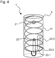
- FIG 4 illustrates an example of a braking device 1 according to the third embodiment of the present invention.
- the braking device 1 of the third embodiment corresponds to that of the second embodiment shown in Figure 3 , except that the range of the extension is limited.
- a second fixing part 22 to slidably fix the lower part of a body 11 to a case 3.
- the fixing part 22 slidably fixes the body 11 at a portion that is above the lower end 13, while more preferably it slidably fixes the lower end 13.
- a plurality of slits 23 are provided on the case 3.
- the fixing part 22 is disposed such that it is fixed to the body 11, being slidable within the slits 23.
- the fixing part 22 is feasible by, for example, screwing a bolt from outside the case 3 through the slits 23 into a nut fixed on the body 11.
- a movable range of the fixing part 22 is limited by the slits 23, and the range of extension of the body 11 is limited thereby.
- the slits 23 are arranged at positions shifted from each other in the longitudinal direction of the case 3. This enables to change at which slit 23 to dispose the fixing part 22 in accordance with the thickness of the rope 2.
- the body 11 is adjustable so as to eliminate the space between the rope 2 and the body 11 of the braking 1 by changing at which slit 23 to dispose the fixing part 22.
- Figure 5 illustrates an example of a braking device 1 according to the fourth embodiment of the present invention.
- the braking device 1 according to the fourth embodiment there are provided a plurality of rod-shaped protection members 4, instead of the case 3, arranged in surrounding of the body 11.
- the same number of rings 41 and 42 as the protection member 4 are provided at an upper end 12 and a lower end 13 of the body 11 respectively, such that the protection members 4 are arranged to pass through respective rings.
- Both ends 43 of the protection members 4 may have a spherical shape with a diameter which is larger than that of the rings 41 and 42, in order to prevent the protection members 4 from slipping off.
- the braking device 1 makes it possible to reduce the risks such as hindering the extension of the body 11 and pinching a user's hand to get injured, even when a user grasps the body 11.
- Figure 6 illustrates a braking device 1 according to the fifth embodiment of the present invention.
- a body 11' is configured of a plurality of plate members 51 to form a cylindrical shape with a square cross section.
- the plate members 51 may have curved shape which is convex to outside the body 11'. That is to say, the plate members 51 may be curved so as to approximate the cross section of the body 11' to a circle.
- a joint member 52 is provided among a plurality of the plate members 51.
- the joint member 52 has a disk shape.
- Figure 7 illustrates how the plate members 51 and the joint member 52 are connected together.
- the joint member 52 has four through holes, each of the plate members 51 also has through holes on its both ends, and the joint member 52 and the plate members 51 are connected together with a pin 53 penetrating the through holes provided on the joint members 52 and the plate members 51 such that each plate members 51 are turnable around the pin 53.
- a plurality of the joint members 52 each of which is connected to four of the plate members 51 are arranged to form a cylindrical shape with a square cross section as described above.
- the end of the plate members 51 the other side of which is connected to one of the joint members 52 is connected to another joint member 52.
- all of the plate members 51 are arranged to make certain angle to the longitudinal direction (the direction parallel to the arrow DN). This causes each of the angles formed by a pair of laterally adjacent plate members 51 to decrease when tension is applied to the body 11' in the DN (or opposite to DN) direction, resulting in extended total longitudinal length and smaller diameter of the body 11'.
- Figure 6(a) illustrates the body 11' when tension is not applied to the hook 15 and Figure(b) illustrates the body 11' when tension is applied to the hook 15.
- L1 a longitudinal length of the body 11', can extend to L2 generating inward stress when force is applied to the body 11' in the DN direction. For this reason, certain space (i.e., a play) may be given between the plate member 51 and the joint member 52 in the joint part connecting the plate members 51 and the joint member 52 with the pin 53.
- the extension of the body 11' generating inward stress causes friction between the body 11' and the rope 2, and it operates as a braking device for the rope 2.
- Figure 8 illustrates a braking device 1 according to the sixth embodiment of the present invention.
- a body 11' of the braking device 1 according to the sixth embodiment has a similar structure to that of the fifth embodiment, except that it has an octagon as a cross section of the cylindrical body 11'.
- all of the plate members 51 are arranged to make certain angle to the longitudinal direction of the body 11' (the direction parallel to the arrow DN).
- Figure 9 illustrates a braking device 1 according to the seventh embodiment of the present invention.
- the body 11' according to the sixth embodiment is housed in a case 3'.
- the case 3' By housing the body 11' in the case 3', it becomes possible to prevent the diameter of the body 11' from unnecessarily expand. As a result, the time required to apply stress on a rope 2 (not shown) to generate friction after pulling a hook 15 in the DN direction is reduced.
- Figure 9 illustrates an example where the braking device 1 is mounted on a wearing tool 5 such as shoes by means of a fixing device 51.
- a wearing tool 5 such as shoes
- a fixing device 51 By fixing the braking device 1 on the user's wearing tools in such a way, it is facilitated to use the braking device 1 as an ascender.
- the braking device 1 of the present embodiment allows the body 11, 11' to apply inward stress approximately uniformly on all around the rope 2. Therefore, it can reduce concentrated stress applied on the surface of the rope 2, compared to the conventional braking device in which a rope is held only from two directions.
- the body 11 is configured of a spring. Therefore, the body 11 shrinks and its diameter expands only by loosening the vertically applied tension (in the longitudinal direction), making the rope 2 movable within the body 11. As a result, a user can easily brake the rope 2.
- the body 11' is configured of a plurality of the plate members 51 turnably connected with a plurality of the joint members 52 such that they are reticularly arranged to form a polygonal cylinder.
- the body 11' is not contractile like the body 11 of the embodiments 1 to 4, the inward stress on all around the rope 2 can be released only by loosening the vertically applied tension (in the longitudinal direction), immediately making the rope 2 movable within the body 11'. As a result, a user can easily brake the rope 2 as well.
- the body 11 has been described to be configured of a spring, it may not necessarily have an elasticity as far as it is deformable such that its diameter becomes smaller when both ends are pulled in the opposite directions.
- the characteristics of the spring such as a form of a wire and a spring constant may be arbitrarily chosen.
- the spring may be a rectangular wire coil spring or an elliptical coil spring.
- a compression spring may also be adopted for the body 11.
- the direction in which the rope 2 extends may be changed by means of a pulley provided in the vicinity of the lower end 13 of the body 11 (preferably the case 3 or the protection member 4 covering the body 11). This allows the rope 2 to be pulled up easily and enables smooth slack tending.
- a body 11' of a braking device 1 in the embodiment 5 and 6 has been described to form a cylindrical shape with a square or an octagonal cross section, it may be a cylindrical shape with any polygonal cross section, without being limited to the described shapes. However, it is preferable not to adopt a triangle for the cross section because the body 11' with a triangle cross section is unable to generate inward stress efficiently due to the nature of a triangle being stable.
- the cross section is a polygon whose number of angles is a multiple of 3
- the plate member 51 is assumed to be a platy component in the embodiment 5 and 6, a rod-shaped component may also be adopted for the plate member 51.
- the plate member 51 may have a curved shape which is convex to outside the body 11' as well as a planar shape. In the case where the plate member 51 is curved, especially in the case where the body 11' is formed of a plurality of the curved plate members 51 to have an approximately circular cross section, when tension is released after being applied to the body11', a repulsive force is generated between the curved plate member 51 and the joint member 52, that is to say, stress toward outside the body 11' is generated, immediately eliminating the friction between the body 11' and the rope 2.
- FIG 11 illustrates a braking device 1 according to the eighth embodiment of the present invention.
- the braking device 1 in the present embodiment assumes to be used as a descender, it can also be used as an ascender.
- the braking device 1 according to the eighth embodiment comprises a body 101 which is formed of extensible material such as resin, metal, or mixture of them (for example, mixed in the ratio of 50:50).
- the body 11' may be integrally molded, for example, by a 3D printer.
- the diameter of the body 101 is determined such that a rope (not shown) is able to pass therethrough, and preferably such that the rope is slidable while the inner surface of the body 101 abuts on the surface of the rope.
- the hook 104 provided at the lower end 103 of the body 101 By coupling the hook 104 provided at the lower end 103 of the body 101 to a user's body, for example, by means of a harness, and pulling down (move in the DN direction in Figure 11 ) the upper end 102 for descending, the diameter of the body 101 expands and therefore friction between the rope and the body 101 is reduced, so that the body 101 can start descending with an appropriately slide.
- a user pulls up the rope (not shown) coupled to the hook 104 in the UP direction or lifts the hook 104 or the lower end 103 up by hand in the UP direction the diameter of the body 101 expands and the rope becomes slidable. The user can ascend by utilizing this mechanism.
- the braking device 1 can apply inward force F in the radial direction approximately uniformly on all around the rope. Therefore, compared to the conventional braking device in which a rope is held only from two directions such as shown in Figure 10 , it can reduce concentrated force applied on the rope (disperse force applied on the surrounding of the rope), leading to reduction of risk of wear and tear especially on the surface of the rope. Because a braking device generates friction and transmits the tension to the rope by contacting the surface of the rope, reducing the damage on the surface of the rope results in preventing tensile strength of the rope from decreasing and in elongating the lifetime thereof.
- the body of the braking device 1 may be integrally molded by a 3D printer, so that the number of components is reduced compared to the case where a plurality of components are assembled. This can suppress variation in quality arising from assembling, leading to reduction in manufacturing man-hours.
- the body 101 is preferably made of a heat-resistant material such as ABS resin and polyester, in consideration of molding by a 3D printer.
- a powder component may be mixed in order to make the rope slide.
- the body 101 may be woven with a plurality of thin ropes formed of fibers such as nylon, polyester, mixed spinning of Technora ® and polyester, and mixed spinning of Kevlar ® and polyester.
- the upper end 102, the lower end 103, and a hook 104 are formed of metal, and the body 101 is formed of a plurality of ropes described above.
- the plurality of ropes may be tied to a plurality of through-holes provided on the upper end 102 and the lower end 103.
- the present braking device may be utilized as a backup device for a winch.
- the braking device 1 of the present embodiment, as well as the first embodiment, can be applied to the other embodiments such as the second embodiment to the extent that it is applicable to the configuration thereof.
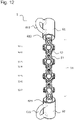
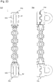
- Figure 12 illustrates a braking device 1 according to the ninth embodiment.
- the braking device 1 comprises a body 11, an upper cylindrical member 61, and a lower cylindrical member 62, the upper and lower cylindrical member being connected to the body 11 at the upper end and the lower end respectively.
- the body 11 is configured by combining a plurality of an approximately disk-shaped joint members 52 and a plurality of an elongated plate members 51.
- the upper cylindrical member 61 and the lower cylindrical member 62 have an approximately cylindrical shape, and each of the members preferably has at least one U-shaped hook 612, 622.
- the upper cylindrical member 61 has an upper joint part 613 connectable to the plate member 51 at the upper end of the body 11, and the lower cylindrical member 62 has a lower joint part 623 connectable to the plate member 51 at the lower end of the body 11, so that the body 11 can connect to the upper cylindrical member 61 and the lower cylindrical member 62.
- Both the upper cylindrical member 61 and the lower cylindrical member 62 have a cylindrical shape as a whole and a through-hole at the center of the cylinder.
- a rope 2 can be inserted into each of the through-holes and the center of the body 11.
- Figure 13 illustrates the upper cylindrical member 61 and the lower cylindrical member 62.
- the upper cylindrical member 61 is representatively shown since the lower cylindrical member 62 may have the same structure.
- Figure 13(a) is a side view and Figure 13(b) is a top view of the upper cylindrical member 61.
- the upper cylindrical member 61 has an approximately cylindrical shape with a though-hole 611 penetrating transversely in the side view so that the rope 2 can pass therethrough.
- the upper cylindrical member 61 may comprise a U-shaped hook 612 on its side surface. It may also comprise the upper joint part 613 on a side connected to the body 11.
- the upper joint part 613 may have any structure to the extent that it is capable of connecting to the body 11, such as a plate-like member similar to the joint member 52 as shown.
- the plate-like member may have a predefined number (2 in Figure 13 ) of through-holes penetrating in the thickness direction so that it can be fixed to the plate member 51 with a pin 53.
- One or more upper joint parts 613 may be provided while exemplary 2 upper joint parts are provided in Figure 13 .
- a hook 612, 622 may be provided on a side surface or an end surface of the upper cylindrical member 61 and the lower cylindrical member 62 respectively.
- the hook 612 is provided on the side surface of the upper cylindrical member 61.
- Figure 14 is an illustration for a case where the hook 612 is provided on the upper end surface.
- the braking device 1 is preferably subject to vertical force when the braking device 1 is vertically pulled up and down by means of the rope 2 coupled to the hook.
- the hook 612, 622 may be mounted to be capable of changing their angle to the cylindrical member.
- a movable member may be provided at a base of the hook where the hook 612 is mounted to the cylindrical member, as shown in the top view of the cylindrical member in Figure 14(b) , such that the end of the hook opposite to the base is able to change its angle in the direction shown by an arrow.
- Making the hooks 612, 622 capable of changing their angle to the cylindrical member can prevent the hooks from hindering a passage of the rope 2.
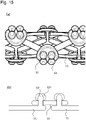
- Figure 15(a) illustrates an enlarged view of the body 11.
- the body 11 is configured of a combination of the plurality of the joint members 52 and the plurality of the plate members 51.
- the joint members 52 have approximately circular disc shapes with a predetermined thickness.
- the joint members 52 have a plurality of through-holes for connecting to the plate members 51.
- One joint member 52 may have four through-holes in the case where it is connected to four plate members 51, as shown in the Figure 15(a) .
- the joint members 52 and the plate members 51 are preferably warped to be convex to the outer side such that they conform to the rope 2 passing through the body 11 in the longitudinal direction.
- Each of the plate members 51 has an elongated shape with a predetermined thickness.
- the elongated plate members 51 are turnably connected to the joint members 52 at their both ends. These members are connected with a pin 53 as shown, but the means for connecting is not limited to this example.
- Figure 15(b) is a cross sectional view of the joint part for the joint member 52 and the plate member 51.
- the plate member 51 may comprise a pin 53 at its end.
- the plate member 51 and the pin 53 may be provided integrally or separately, while it is preferable that the undersurface (the side contacting the rope 2) of the plate member 51 is a plane surface without the pin 53 projecting from the surface in order for the rope 2 to slide.
- the joint member 52 may comprise through-holes preferably designed to have a diameter to make space around the pin 53 so that the plate member 51 is turnable with respect to the joint member 52.
- the pin 53 may have a cap 531 for preventing the plate member 51 from dropping out from the joint member 52, as required.
- the plate member 51 only needs to be connected to the joint member 52 so as to be turnable with respect to the joint member 52.
- the connecting mechanism is not limited to that by a pin shown in Figure 15 , but may be the other mechanisms such as by a hinge.
- the joint member 52 joins four plate members 51 with each other.
- a plurality of the joint members 52 are arranged such that they make a plurality of pairs, each of the pair is located to face each other at longitudinally corresponding position, and each pair makes a 90 degrees angle along the circumferential direction of the body 11 with respect to a longitudinally adjacent pair at an equal longitudinal interval. It is preferable to provide odd number of the pair of the joint member 52 so as to make it symmetric against a longitudinal center of the body 11. In the example of Figure 12 , seven pairs of the joint member 52 shown as 52-1 to 52-7 are provided.
- the upper cylindrical member 61 and the lower cylindrical member 62 may be formed of metal, ceramic, resin, or mixture of them determined with consideration of strength and durability.
- the joint member 52 and the plate member 51 may be formed of metal, ceramic, resin, or mixture of them, determined with consideration of frictional characteristics and strength. For example, they may be formed of metal such as stainless, aluminum, and titanium, or resin such as ABS resin and MC nylon.
- providing the upper cylindrical member 61 and the lower cylindrical member 62 makes it easier for a user to grasp and operate the braking device 1 in a vertical move.
- a longitudinal length of a cylindrical member shown as L1 is 20mm-100mm, preferably 40mm-60mm with consideration of usability (i.e., ease to grasp).
- An outer diameter of the cylindrical member shown as L2 is 15mm-50mm, preferably 25mm-35mm with consideration of strength.
- a size of the hook 612 along the direction perpendicular to the longitudinal direction, shown as L3, only needs to allow a rope to be tied thereto, being, for example, 10-50mm, preferably 20-35mm.
- An inner diameter of the cylindrical member shown as L4 is designed to be slightly larger than the diameter of the rope 2, being, for example, 12.5mm-16mm, preferably and approximately 14mm.
- FIG 16 illustrates the exemplary variation 1 of the ninth embodiment.
- at least one of the through-holes 611, 621 of the upper cylindrical members 61 and the lower cylindrical members 62 comprises projections 614, 624.
- the projections 614, 624 serve as a trigger to generate friction between the rope 2 and the braking device 1. If a gap between the diameter of the rope 2 and the inner diameter of the upper cylindrical member 61 or the lower cylindrical member 62 is too small, it hinders smooth move when the rope 2 passes through the braking device or when the braking device is lifted up, whereas if the gap is too large, friction is hardly generated when the braking device is extended to stop sliding relative to the rope 2. For this reason, projections 614, 624 are provided on at least one of the upper cylindrical members 61 and the lower cylindrical members 62. By providing the projections 614, 624, generation of friction can be appropriately triggered upon extension of the braking device 1.
- Figure 16(a) and Figure 16(b) are a bottom view and a side view of the lower cylindrical member 62 respectively, and Figure 16(c) is a top view of the upper cylindrical member 61.
- the lower cylindrical member 62 comprises the projections 624 on the inner surface of the through hole 621.
- the projections 624 are formed with certain thickness to abut on the rope 2.
- the thickness can be set to a size approximately equal to or slightly smaller than the difference between the diameter of the through hole 621 and that of the rope 2.
- the thickness of the projections 624 can be set to 1mm.
- the projections 624 can be thin and elongated in the longitudinal direction of the through hole 621 of the lower cylindrical member 62, having a predetermined length, as shown in Figure 16(b) , while the shape of the projections is not limited to this example.
- the other examples can be small projections 624 aligned at equal intervals as shown in Figure 17(a) and that aligned spirally along the inner surface of the through hole 621 in the longitudinal direction, as shown in Figure 17(b) .
- the number of the projections and the substantial length thereof in total may be different between the upper cylindrical member 61 and the lower cylindrical member 62 such that the upper cylindrical member 61 has more projections than the lower cylindrical member 62.
- the lower cylindrical member 62 has three projections 624 and the upper cylindrical member 61 has four projections 614. This is aimed to generate larger friction at the upper cylindrical member 61 than at the lower cylindrical member 62 when pulling down the lower cylindrical member 62 to generate friction.
- the number of projections at each cylindrical member can be suitably designed with consideration of the difference of friction, while not limited to the foregoing example.
- the material of the projections may be metal, resin, ceramic, or mixture of them.
- Figures 18 to 21 illustrate the exemplary variation 2 of the ninth embodiment of the present invention. This example is aimed to maximize the elasticity in order to maximize friction to be generated upon extending.
- Figure 21(a) is a schematic development view of the body 11, and the Figure 21(b) is a side view thereof. Both of the figures show the body 11 in the most contracted state.
- the plate members 51 are ideally laid approximately horizontally and aligned to contact tightly with adjoining ones as shown in Figure 21(a) , in the most contracted state.
- the braking device 1 of the present invention stops moving relative to the rope 2 by means of friction generated upon extension of the body 11, and generated friction can be larger dependent on the elasticity of the braking device 1 at the start of extension.
- the friction is maximized by starting extension from the most elastic state shown in Figure 21(a) .
- the plate members 51 are more spaced from each other at the most contracted state compared to the illustration of Figure 21(a) , the friction generated upon extension is smaller than the maximum friction.
- the elasticity is increased by comprising a movable mechanism 615, 625 on at least one of the upper joint part 613 and the lower joint part 623.
- a movable mechanism 615, 625 on at least one of the upper joint part 613 and the lower joint part 623.
- the movable mechanism 615 enables the end of the upper joint part 613 in the side connected to body 11 to turn outward relative to the rope 2. That is to say, by having the movable mechanism 615, the end of the upper joint part 613 is enabled to open to the outside as shown in Figure 21(b) .
- This upper joint part 613 capable of opening to the outside facilitates the body 11 to be extended and contracted, leading to increase in elasticity.
- the structure of the movable mechanism 615 can be, for example, a hinge, while it is not limited herein.
- a rod-shaped member may be arranged on the base part of the upper joint part 613 to serve as a turning shaft, and the end part of the upper joint part 613 is coupled thereto so as to be turnable along the surface of the rod-shaped member.
- Figure 18 illustrates an example of the movable mechanism 615 by a hinge.
- Figure 18(a), (b) illustrate the upper cylindrical member 61, wherein Figure18(a) is a top view of the movable mechanism 615, and Figure 18(b) is a side view of movable mechanism 615.
- the movable mechanism 615 comprises two rings 6151A, 6151B on the lower end surface of the upper cylindrical member 61.
- the rings 6151A, 6151B are turnably coupled to the movable mechanism 615 by passing through the openings 6152A, 6152B respectively while coupled to the upper joint part 613.
- Such configuration enables the rings 6151A, 6151B to be coupled to the upper cylindrical member 61 in a state where they are turnable to the outside (toward the opposite side of the rope 2).
- Figure 19 illustrates another example of the movable mechanism 615 by a hinge.
- the movable mechanism 615 of this example is different from that of Figure 18 in that it comprises only a single ring 6151A.
- the ring 6151A is turnably coupled to the movable mechanism 615 by passing through the opening 6152A, while coupled to the upper joint part 613.
- Figure 20 illustrates further example of the movable mechanism 615 by a hinge.
- the movable mechanism 615 comprises a turning shaft, and the movable mechanism is coupled to the upper joint part 613 in a state where the upper joint part 613 is turnable around the turning shaft.
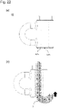
- Figure 22 illustrates the exemplary variation 3 of the ninth embodiment of the present invention.
- the present exemplary variation is characterized by a curved surface 616, 626 formed on at least one of the upper cylindrical member 61 and the lower cylindrical member 62, at an edge where an inner surface of the through holes 611, 621 meets an end surface in the side opposite to the body 11.
- An example of the lower cylindrical member 62 is described below while the upper cylindrical member 61 may be the same.
- the lower cylindrical member 62 has a curved surface 626 at the lower edge of the inner surface of the through hole 621.
- the curved surface 626 preferably has an R-shape.
- the curved surface 626 is formed at least at the lower edge of the inner surface of through hole 621, more preferably formed at the lower edge of the outer surface as well, as shown in Figure 22 . According to the present variation, the curved surface 626 can prevent the rope 2 from being caught by the lower edge when lifting up the lower end of the braking device 1 by pulling up the rope 2 in the direction shown by an arrow in Figure 22(b) .
- Figures 23 to 26 illustrate the exemplary variation 4 of the ninth embodiment of the present invention.
- at least one of the upper cylindrical member 61 and the lower cylindrical member 62 comprises an opening and closing mechanism 71, 72 capable of opening and closing the side wall.
- An example of the upper cylindrical member 61 is described below while the lower cylindrical member 62 may be the same.
- Figure 25 schematically illustrates the lower end surface of the upper cylindrical member 61.
- the upper cylindrical member 61 comprises a first member 711 and a second member 712.
- the first member 711 and the second member 712 contact with each other along the longitudinal direction of the cylindrical member such that they form a cylindrical shape as a whole in a closed state.
- the first member 711 and the second member 712 are turnably coupled to each other at one coupling side by means of a turning shaft penetrating both members.
- the first member 711 and the second member 712 comprise a through hole 714 penetrating both members, so that the both members can be locked in the closed state by inserting a fixing pin 715 into the through hole 714.
- Figure 25(a) illustrates the upper cylindrical member 61 in a closed state where the first member 711 and the second member 712 are coupled to each other at both coupling sides to form a cylindrical shape as a whole
- Figure 25(b) illustrates the upper cylindrical member 61 in an opened state where the first member 711 and the second member 712 are coupled at a coupling side with a turning shaft 713, such that the first member 711 is turnable around the turning shaft 713.
- Figure 26(a) is a side view of the upper cylindrical member 61 and the Figure 26(b) is a sectional view thereof.
- the first member 711 and the second member 712 are formed to overlap alternately at the coupling side as shown in Figure26(a) .
- the turning shaft 713 is disposed to penetrate the overlapping part of the first member 711 and the second member 712, so that the first member 711 and the second member 712 can be turnably coupled and held in the state.
- the fixing pin 715 can also be inserted to penetrate the overlapping part of the first member 711 and the second member 712 at the other side.
- the braking device 1 When using the braking device 1 according to the present invention, firstly it is unlocked by removing the fixing pin 715 and then the first member 711 is turned around the turning shaft 713 to make it into the opened state ( Figure 25(b) ). Subsequently, the rope 2 is inserted into the through hole 611, the first member 711 is closed to make it into the closed state ( Figure 25(a) ), and then the fixing pin 715 is inserted to the fixing pin through hole 714 to lock the first member 711 and the second member 712 in the closed state.
- the fixing pin through hole 714 may have any structure such as a key groove at its end in order to prevent the fixing pin 715 from slipping off.
- the opening and closing mechanism 71, 72 provided on at least one of the upper cylindrical member 61 and the lower cylindrical member 62 can facilitate the setting of the rope 2 inserting into the through hole.
- a diameter expanding mechanism to expand the diameter of through hole of the upper cylindrical member 61 and the lower cylindrical member 62 may be provided instead of the opening and closing mechanism 71, 72.
- the diameter expanding mechanism only needs to be capable of expanding the through hole when inserting the rope 2 and shrinking the expanded diameter before using, while the mechanism is not limited herein.
- the braking device 1 may be vertically symmetric.
- the braking device 1 is similarly usable no matter which is a top or a bottom if the upper cylindrical member 61 and the lower cylindrical member 62 have the same configuration. This vertically symmetric property can reduce a risk of accidents due to incorrect use on site, consequently leading to better ease of use.
Landscapes
- Health & Medical Sciences (AREA)
- Engineering & Computer Science (AREA)
- General Engineering & Computer Science (AREA)
- General Health & Medical Sciences (AREA)
- Mechanical Engineering (AREA)
- Business, Economics & Management (AREA)
- Emergency Management (AREA)
- Pulmonology (AREA)
- Physical Education & Sports Medicine (AREA)
- Braking Arrangements (AREA)
- Emergency Lowering Means (AREA)
Applications Claiming Priority (2)
| Application Number | Priority Date | Filing Date | Title |
|---|---|---|---|
| JP2019111946A JP6578503B1 (ja) | 2019-06-17 | 2019-06-17 | 制動装置 |
| PCT/JP2020/022150 WO2020255735A1 (fr) | 2019-06-17 | 2020-06-04 | Dispositif de frein |
Publications (2)
| Publication Number | Publication Date |
|---|---|
| EP3984600A1 true EP3984600A1 (fr) | 2022-04-20 |
| EP3984600A4 EP3984600A4 (fr) | 2024-01-17 |
Family
ID=68053467
Family Applications (1)
| Application Number | Title | Priority Date | Filing Date |
|---|---|---|---|
| EP20827907.5A Pending EP3984600A4 (fr) | 2019-06-17 | 2020-06-04 | Dispositif de frein |
Country Status (3)
| Country | Link |
|---|---|
| EP (1) | EP3984600A4 (fr) |
| JP (1) | JP6578503B1 (fr) |
| WO (1) | WO2020255735A1 (fr) |
Families Citing this family (1)
| Publication number | Priority date | Publication date | Assignee | Title |
|---|---|---|---|---|
| JP6578503B1 (ja) * | 2019-06-17 | 2019-09-25 | 株式会社マルイチ | 制動装置 |
Family Cites Families (15)
| Publication number | Priority date | Publication date | Assignee | Title |
|---|---|---|---|---|
| US2773566A (en) * | 1953-06-08 | 1956-12-11 | William F Staggers | Automatic hitch |
| US3470982A (en) * | 1968-07-18 | 1969-10-07 | Thomas B Warden Jr | Rope gripping device for climbing ropes |
| JPS5419885U (fr) * | 1977-07-11 | 1979-02-08 | ||
| FR2403803A1 (fr) * | 1977-09-22 | 1979-04-20 | Hottelet Michel | Frein lineaire prereglable pour deplacement vertical ou horizontal |
| DK28481A (da) * | 1980-01-29 | 1981-07-30 | G Siegmann | Skoedeklemme |
| JPS59130748U (ja) * | 1983-02-23 | 1984-09-01 | 斉藤 貞二 | 滑降式避難用具 |
| DE3531200A1 (de) * | 1985-08-31 | 1986-05-22 | Hans-Günter Bieber | Doppelfeder-blockiersystem (schraubenfeder mit doppelten endabknickungen) |
| CA2216216A1 (fr) * | 1997-11-18 | 1999-05-18 | Christopher Francis Herbst | Systeme d'auto-evacuation d'urgence |
| US8235172B2 (en) * | 2004-06-01 | 2012-08-07 | Morgan Thompson | Combination ascender/descender |
| JP5109906B2 (ja) * | 2008-09-29 | 2012-12-26 | トヨタ自動車株式会社 | ワイヤー送給チューブ、ワイヤー送給装置、及び、アーク溶接装置 |
| FR2938771B1 (fr) | 2008-11-27 | 2010-12-31 | Zedel | Dispositif bloqueur a came pour l'assurage sur corde fixe |
| FR2961709B1 (fr) * | 2010-06-23 | 2012-12-07 | Zedel | Appareil bloqueur descendeur pour la remontee et la descente sur corde |
| GB2572826B (en) * | 2018-04-13 | 2021-02-10 | Treemagineers Ltd | Pulley assembly with rope passage of varying cross-section |
| JP6578502B1 (ja) * | 2019-05-14 | 2019-09-25 | 株式会社マルイチ | 制動装置 |
| JP6578503B1 (ja) * | 2019-06-17 | 2019-09-25 | 株式会社マルイチ | 制動装置 |
-
2019
- 2019-06-17 JP JP2019111946A patent/JP6578503B1/ja active Active
-
2020
- 2020-06-04 EP EP20827907.5A patent/EP3984600A4/fr active Pending
- 2020-06-04 WO PCT/JP2020/022150 patent/WO2020255735A1/fr unknown
Also Published As
| Publication number | Publication date |
|---|---|
| EP3984600A4 (fr) | 2024-01-17 |
| JP2020202961A (ja) | 2020-12-24 |
| JP6578503B1 (ja) | 2019-09-25 |
| WO2020255735A1 (fr) | 2020-12-24 |
Similar Documents
| Publication | Publication Date | Title |
|---|---|---|
| CN104740848B (zh) | 改进型滑轮装置 | |
| US20230065262A1 (en) | Harnesses | |
| US11382405B2 (en) | Lanyard | |
| KR102128867B1 (ko) | 릴 기반 끈 조임 시스템 | |
| AU2011224603B2 (en) | Pole climbing fall prevention assembly | |
| CA2613686C (fr) | Systeme et methodes pour le controle de corde | |
| JP6606540B2 (ja) | 取り付け装置 | |
| US10221918B2 (en) | Rope tension device and method thereof | |
| US10023445B2 (en) | Portable power driven system comprising a rope grab arrangement | |
| EP3984600A1 (fr) | Dispositif de frein | |
| JP6553737B2 (ja) | 安全固定システム、安全固定システムに使用可能なカラビナ、および安全固定システムを含む固定組立品 | |
| KR101334750B1 (ko) | 상호 역방향으로 대향한 이중쐐기를 사용하여 체결력을 높인 케이블 고정장치 및 이 케이블 고정장치가 구비된 고정형 케이블 정착구 | |
| US9370692B2 (en) | Active cam device | |
| US20180229356A1 (en) | Side Handle | |
| TW201410299A (zh) | 具有可旋轉本體的安全繩索阻擋器 | |
| EP3095951A1 (fr) | Casier a cordon reglable et store de fenetre ayant un tel casier a cordon reglable | |
| CA1171642A (fr) | Connecteur de cable | |
| WO2013155225A1 (fr) | Dispositif de réglage de câble | |
| US10238524B2 (en) | Tightening system for orthotics | |
| US20060081418A1 (en) | Ascender/descender | |
| JP6578502B1 (ja) | 制動装置 | |
| KR102021602B1 (ko) | 그라운드 앵커용 강연선 재긴장 장치 | |
| CN100376302C (zh) | 用于悬挂和锁定攀登用绳索的装置 | |
| JP6708891B1 (ja) | 制動装置 | |
| US11135479B2 (en) | Anchors for climbing and related activities |
Legal Events
| Date | Code | Title | Description |
|---|---|---|---|
| STAA | Information on the status of an ep patent application or granted ep patent |
Free format text: STATUS: THE INTERNATIONAL PUBLICATION HAS BEEN MADE |
|
| STAA | Information on the status of an ep patent application or granted ep patent |
Free format text: STATUS: THE INTERNATIONAL PUBLICATION HAS BEEN MADE |
|
| PUAI | Public reference made under article 153(3) epc to a published international application that has entered the european phase |
Free format text: ORIGINAL CODE: 0009012 |
|
| STAA | Information on the status of an ep patent application or granted ep patent |
Free format text: STATUS: REQUEST FOR EXAMINATION WAS MADE |
|
| 17P | Request for examination filed |
Effective date: 20210118 |
|
| AK | Designated contracting states |
Kind code of ref document: A1 Designated state(s): AL AT BE BG CH CY CZ DE DK EE ES FI FR GB GR HR HU IE IS IT LI LT LU LV MC MK MT NL NO PL PT RO RS SE SI SK SM TR |
|
| DAV | Request for validation of the european patent (deleted) | ||
| DAX | Request for extension of the european patent (deleted) | ||
| A4 | Supplementary search report drawn up and despatched |
Effective date: 20231215 |
|
| RIC1 | Information provided on ipc code assigned before grant |
Ipc: A63B 29/02 20060101ALI20231211BHEP Ipc: F16D 63/00 20060101ALI20231211BHEP Ipc: F16D 49/02 20060101ALI20231211BHEP Ipc: A62B 1/14 20060101AFI20231211BHEP |