EP3984148B1 - Ausrichtung einer verwickelten photonenquelle - Google Patents
Ausrichtung einer verwickelten photonenquelle Download PDFInfo
- Publication number
- EP3984148B1 EP3984148B1 EP20732911.1A EP20732911A EP3984148B1 EP 3984148 B1 EP3984148 B1 EP 3984148B1 EP 20732911 A EP20732911 A EP 20732911A EP 3984148 B1 EP3984148 B1 EP 3984148B1
- Authority
- EP
- European Patent Office
- Prior art keywords
- beam splitter
- polarizing beam
- clockwise
- sagnac loop
- photon
- Prior art date
- Legal status (The legal status is an assumption and is not a legal conclusion. Google has not performed a legal analysis and makes no representation as to the accuracy of the status listed.)
- Active
Links
Images


Classifications
-
- G—PHYSICS
- G02—OPTICS
- G02B—OPTICAL ELEMENTS, SYSTEMS OR APPARATUS
- G02B6/00—Light guides; Structural details of arrangements comprising light guides and other optical elements, e.g. couplings
- G02B6/24—Coupling light guides
- G02B6/26—Optical coupling means
- G02B6/28—Optical coupling means having data bus means, i.e. plural waveguides interconnected and providing an inherently bidirectional system by mixing and splitting signals
- G02B6/293—Optical coupling means having data bus means, i.e. plural waveguides interconnected and providing an inherently bidirectional system by mixing and splitting signals with wavelength selective means
- G02B6/29346—Optical coupling means having data bus means, i.e. plural waveguides interconnected and providing an inherently bidirectional system by mixing and splitting signals with wavelength selective means operating by wave or beam interference
- G02B6/29347—Loop interferometers, e.g. Sagnac, loop mirror
-
- H—ELECTRICITY
- H04—ELECTRIC COMMUNICATION TECHNIQUE
- H04B—TRANSMISSION
- H04B10/00—Transmission systems employing electromagnetic waves other than radio-waves, e.g. infrared, visible or ultraviolet light, or employing corpuscular radiation, e.g. quantum communication
- H04B10/70—Photonic quantum communication
Definitions
- the invention concerns a method to align a Sagnac loop for an entangled photon source according to claim 1 and a Sagnac loop with an apparatus to provide an aligned Sagnac loop for an entangled photon source according to claim 10.
- Entangled photon sources are well known for example as a BBO source from US 6 424 665 B1 or as Sagnac ppKTP type-II source from "A space-suitable, high brilliant entangled photon source for satellite base quantum key distribution" or as a pulsed type-0 PPLN source from "Pulsed Sagnac source of polarization-entangled photon pairs in telecommunication band” or as fiber Sagnac configuration from US 6 897 434 B1 . From Heonoh Kim et al: "Pulsed Sagnac source of polarization-entangled photon pairs in telecommunication band" arXiv.1904.00164 a polarization-entangled photon source with a Sagnac configuration is known.
- the second and/or third polarizing beam splitter is arranged in the third and/or fourth output path of the first polarizing beam splitter, and the observation in the output path of the second and/or third polarizing beam splitter is performed by a measurement of the optical power of the clockwise and counter-clockwise photon beams with a power-meter, and/or a detection of the interference pattern of the clockwise and counter-clockwise photon beams with a camera or an optical component with a surface to monitor the interference.
- a polarizing beam splitter comprises four sides, on each side a corresponding output and input path for the polarized photon beam and the down conversion photon beam is assigned.
- Input path means that a beam enters the polarizing beam splitter on this side.
- Output path means that a beam exits the polarizing beam splitter on this side.
- the polarizing beam splitter splits a photon beam into two, whereas the reflected photon beam is vertically polarized (V) and the transmitted photon beam is horizontally polarized (H).
- the reflected polarized photon beam exits the first polarizing beam splitter on the second output path and travels in clockwise direction and is guided by the mirrors into the first input path of the first polarizing beam splitter.
- first and second input and output paths meaning the clockwise and counter clockwise directions
- the polarized photon beam in front of the first polarizing beam splitter can have any other polarization but not pure linear horizontal or vertical polarized. This can be achieved and can be controlled by a half-wave plate and/or a quarter-wave plate and/or a polarizer in front of the first polarizing beam splitter.
- Tip-tilt or so called two axes tilt means a movement of the mirror around two axes (preferably horizontal and vertical) where each movement around one axis can be performed independently.
- a tip-tilt movement of the two mirrors in the Sagnac loop the polarized photon beams of the clockwise and counter-clockwise direction can be brought to a spatial overlap.
- the first arrangement of the optical components in a Sagnac loop configuration means that the clockwise and counter-clockwise paths of the polarized photon beams in the Sagnac loop are guided at least to meet the first polarizing beam splitter in the first and second input path. It means at least one Sagnac loop should be formed by the components. In the optimization steps the clockwise and counter-clockwise path are successive brought to a spatial overlap by the tip-tilt movement of the mirrors.
- a polarization flip element preferably a half-wave plate or a dual wavelength half-wave plate is arranged inside the loop.
- the polarization flip element can be removed or placed in a polarization neutral setting. In this case the light will exit through the initially un-used output path (i.e. the port that is not facing the input path or the two-forming part of the Sagnac loop).
- a polarizing element in the pump input path can also be used to inspect the pump light.
- the tip/tilt movement of the mirrors and a detection and/or minimization of the interference in the reflection output of the second and/or third polarizing beam splitter arranged at the third or fourth side of the first polarizing beam splitter is performed in order to optimize the spatial overlap of the clockwise and counter-clockwise propagation beams in the Sagnac loop.
- the measurement or detection of the counter-clockwise and clockwise propagating polarized photon beams provides information on the alignment of the loop. This means if the loop is strongly misaligned, there will be two spots on the camera or any other optical component with a surface to monitor the beams and/or the interference; one for each of the two propagation paths (i.e. clockwise / counter-clockwise). These two beams can be brought to overlap by adjustment of the mirrors inside the loop. Once the beams overlap, the procedure proceeds with tests of the interference visibility. This interference is in the polarization state of the two beams; i.e. imperfect overlap results in a spatially varying polarization state of the beam emerging from the Sagnac loop.
- the phase between the horizontal and vertical pump polarization components is translated to an intensity signal.
- This can be accomplished by placing a polarizing beam splitter outside of the Sagnac loop in the path of the polarized photon beams which are leaving the Sagnac loop, e.g. a polarizer, is added to the setup.
- This polarizer can be oriented at 45°, so that the linear horizontal beam (corresponding to clockwise / or counter-clockwise propagation inside the loop) and the linear vertical beam (corresponding to counter-clockwise / or counter propagation inside the loop) interfere to produce a spatially varying intensity pattern (i.e. interference pattern) after the polarizer.
- the characteristic interference pattern after the polarizing beam splitter also provides information on the nature of the misalignment of the loop.
- the number of fringes relates to the amount of angular misalignment. If these fringes are oriented vertically (horizontally), then the misalignment is mainly in the horizontal (vertical) plane.
- the alignment procedure thus aims to minimize the number of fringes.
- the goal of the alignment procedure is to have a single interference minimum that extends across the whole beam. In the case of optimal beam overlap, the superposition of the counter-clockwise and clockwise propagation pump beam components results in a uniform polarization state across the beam diameter.
- the shape and form of these fringes may also indicate other types of misalignment: for example, if the fringes are concentric rings then this may indicate transverse misalignment of the focus, that the focus of the beams is not at the centre of the Sagnac loop.
- the tip/tilt movement of the two mirrors and a minimization or maximization of the measured optical power in the reflection output of the second and/or third polarizing beam splitter arranged at the third or fourth side of the first polarizing beam splitter is performed in order to optimize the spatial overlap of the clockwise and counter-clockwise propagation beams in the Sagnac loop.
- the tip/tilt movement of the mirrors and a maximization of the measured optical power in the reflection output of the third polarizing beam splitter arranged at same side as the light source is performed in order to optimize the spatial overlap of the clockwise and counter-clockwise propagating beams in the Sagnac loop, wherein the third beam splitter is arranged between the light source and the first polarizing beam splitter, and wherein in addition between the third polarizing beam splitter and the first polarizing beam splitter a non-reciprocal optical device, preferably a Faraday-rotator, and a polarizer at 45° is arranged.
- the non-reciprocal optical device and the polarizer at 45° is a Faraday isolator or optical isolator.
- the Sagnac loop comprises a first polarized photon beam to align the Sagnac loop, whereby the Sagnac loop is formed by a first polarizing beam splitter, and two mirrors arranged in a first and second output path of the first polarizing beam splitter, forming a clockwise and counter-clockwise path for the photon beam behind the first polarizing beam splitter, wherein the polarized photon beam of the first light source enters the first polarizing beam splitter on a third or fourth output path, wherein the entangled photon source comprises at least the following optical components:
- the first polarized photon beam is emitted by an auxiliary light source and the second polarized photon beam is emitted by a pump laser, whereas the first and the second polarized photon beams overlap spatially in the Sagnac loop.
- first and the second polarized photon beams are emitted by one light source, or the same light source, whereas the first and the second polarized photon beams are the same.
- the method includes a further step between step IV) and step V): performing one or more alignment steps of the first coupling means by a tip/tilt movement and focus of the first coupling means in order to maximize the measured power of an additional alignment beam detected in the first coupling means, wherein the additional alignment beam enters the entangled photon source by the second coupling means, and/or performing one or more alignment steps of the second coupling means by a tip/tilt movement and focus of the second coupling means in order to maximize the measured power of an additional alignment beam detected in the second coupling means, wherein the additional alignment beam enters the entangled photon source by the first coupling means.
- a control device is capable to provide an alignment method, wherein the control device is connected
- a control device is provided wherein the control device is additional connected with the first and second coupling means in order to perform the tip/tilt movement and/or focus adjustment and a first and second detection means in order to monitor the collected light in the first and second coupling means.
- a computer device with a microprocessor with a nonvolatile memory wherein the nonvolatile memory comprises an executable program in order to provide one of the above-mentioned methods, preferably wherein the computer device is the control device.
- an apparatus to provide a method according to one of the above-mentioned methods is provided.
- an entangled photon source comprising a Sagnac loop and an apparatus to provide an aligned Sagnac loop
- the entangled photon source comprises at least the following optical components:
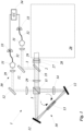
- Fig. 1 shows an entangled photon source 1 in Sagnac configuration.
- the Sagnac loop 10 is formed by a first polarizing beam splitter 11 and two mirrors 12. In the middle of the Sagnac loop 10 a crystal 13 is arranged.
- the Sagnac loop 10 is pumped by the polarized photon beam 2 emitted from a laser 21 (not shown in Fig. 1 ).
- a lens 29 or a lens system focus the polarized photon beam 2 into the crystal 13 in the Sagnac loop.
- the crystal 13 is a type-II down conversion crystal 13 for example a ppKTP (Potassium titanyl phosphate) crystal oriented so that when pumped by a horizontal polarized photon beam 2 pairs of down conversion photons with orthogonal polarization, e.g. horizontal (H) and vertical (V) polarization are produced.
- a dual wavelength half-wave plate 14 is arranged in the Sagnac loop to change the polarization of all incoming photons of the polarized photon beam 2 and the down conversion photon beam 3 linearly by 90°, e.g. from horizontal (H) to vertical (V).
- This dual wavelength half-wave plate 14 is not always necessary for the alignment of the Sagnac loop but to ensure the entanglement in the entangled photon source.
- the first polarizing beam splitter 11 comprises four sides, on each side a corresponding output and input path for the polarized photon beam 2 and the down conversion photon beam 3 is assigned.
- Input path means that beams enter the first polarizing beam splitter 11 on this side.
- Output path beams exit the first polarizing beam splitter 11 on this side. This also applies for all the following polarizing beam splitters.
- the first polarizing beam splitter 11 splits a photon beam into two, whereas the reflected photon beam is vertically polarized (V) and the transmitted photon beam is horizontally polarized (H).
- the two mirrors 12 of the Sagnac loop 10 are arranged in a first and second output path of the first polarizing beam splitter 11.
- the polarized photon beam in Fig. 1 enters the first polarizing beam splitter 11 on a third input path (right side of the first polarizing beam splitter 11).
- the transmitted photon beam exits the first polarizing beam splitter 11 on the first output path (left side of the first polarizing beam splitter 11) and travels in counter-clockwise direction (counter-clockwise arrow in Fig.
- the first and second input and output paths (meaning the clockwise and counter-clockwise directions) of the polarized photon beams overlap spatially.
- the down conversion photon pairs are split by the first polarizing beam splitter 11, are guided by mirrors 12, a dichroic mirror 35 and focused by a lens or lens system 29 and a coupling means 31 into single mode fibers 32, which are connected to photon-detectors 33.
- the signal of the photon-detectors 33 is counted in a coincidence logic 34 to register single photon events and coincidence events detected on the photon-detectors 33.
- a half-wave-plate 27 and a quarter-wave-plate 28 are arranged in the polarized photon beam 2 before the first polarizing beam splitter 11.
- Fig. 2 shows the Sagnac loop 10 with counter-clockwise pump direction and a first embodiment of the alignment components comprising a second polarizing beam splitter 22, a first light source 21 and a power-meter 24.
- the first light source 21 emits the polarized photon beam 2.
- the polarized photon beam 2 transmitted in the second polarizing beam splitter 22 is horizontal polarized. The horizontal polarization is not changed by the half-wave-plate 27 at 0° leading to a counter-clockwise pump direction in the Sagnac loop.
- the polarized photon beam 2 in the Sagnac loop is rotated to a vertical polarization by the dual wavelength half-wave-plate 14 so that the polarized photon beam 2 is reflected in the first polarizing beam splitter 11, not rotated on the way towards the second polarizing beam splitter 22 by the half-wave-plate 27 leading to a reflection of the polarized photon beam 2 on the second polarizing beam splitter 22.
- the polarized photon beam 2 is detected by a power-meter 24 on the reflection output of the second polarizing beam splitter 22.
- Fig. 3 shows the Sagnac loop 10 with clockwise pump direction and the first embodiment of the alignment components corresponding of Fig. 2 .
- the first light source 21 emits the polarized photon beam 2.
- the polarized photon beam 2 transmitted in the second polarizing beam splitter 22 is horizontal polarized.
- the horizontal polarization can be changed to a linear vertical polarization by the half-wave-plate 27 at 45° leading to a clockwise pump direction in the Sagnac loop.
- the polarized photon beam 2 in the Sagnac loop is rotated to a horizontal polarization by the dual wavelength half-wave-plate 14 so that the polarized photon beam 2 is transmitted in the first polarizing beam splitter 11, rotated again to a vertical polarization on the way towards the second polarizing beam splitter 22 by the half-wave-plate 27 leading to a reflection of the polarized photon beam 2 on the second polarizing beam splitter 22.
- the polarized photon beam 2 is detected by a power-meter 24 on the reflection output of the second polarizing beam splitter 22.
- Fig. 4 shows the Sagnac loop 10 and the first embodiment of the alignment components corresponding to Fig. 2 for both, the clockwise and counter-clockwise pump direction.
- the half-wave-plate 27 is arranged at 22,5° to rotate the horizontal polarized photon beam 2 transmitted by the second polarizing beam splitter 22 to a 45° linear polarization.
- the Sagnac loop 10 is then pumped in both directions and the polarized photon beams 2 from both directions can be detected on the power-meter 24.
- the spatial overlap of the polarized photon beams 2 in the Sagnac loop 10 can be aligned by the measurement of the power of the polarized photon beams 2 on the power-meter 24.
- the spatial overlap of the clockwise and counter-clockwise polarized photon beams 2 can be aligned by so called tip-tilt (or two axes tilt) movement of the two mirrors 12 in the Sagnac loop 10.
- Tip-tilt means a movement of the mirror around two axes where each movement around one axis can be performed independently.
- the polarized photon beams 2 in the Sagnac loop can be brought to a spatial overlap. This can be monitored by the increase of the power on the power-meter 24.
- Fig. 5 shows a second embodiment of the alignment components comprising a second polarizing beam splitter 22, a first light source 21 and a monitor 23.
- the monitor 23 can be a camera or any other optical component with a surface to monitor the polarized photon beam 2.
- the spatial overlap of the polarized photon beams 2 in the Sagnac loop 10 can be detected by the overlap or the interference pattern of the two the polarized photon beams 2 (clockwise and counter-clockwise) on the monitor 23.
- Fig. 6 shows the first embodiment of the alignment components from Fig. 2 to 4 .
- Fig. 7 shows a third embodiment of the alignment components comprising a second polarizing beam splitter 22, a first light source 21 and a power-meter 24, a non-reciprocal optical device 25 and a polarizer 36.
- the spatial overlap of the polarized photon beams 2 in the Sagnac loop 10 can be detected by a maximization of the optical power of the polarized photon beams 2 on the power-meter 24.
- Fig. 8 shows a fourth embodiment of the alignment components. These differ from the components in Fig. 7 only in additional coupling means 31, lenses 29 and a fiber 32 to connect the Sagnac loop 10 (not shown in Fig. 8 ) and the pump and alignment components section 20.
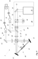
- Fig. 9 shows an entangled photon source 1 from Fig. 1 with the first embodiment of the alignment components of Fig. 2 to 4 and Fig. 6 .
Landscapes
- Physics & Mathematics (AREA)
- Optics & Photonics (AREA)
- Electromagnetism (AREA)
- Engineering & Computer Science (AREA)
- Computer Networks & Wireless Communication (AREA)
- Signal Processing (AREA)
- General Physics & Mathematics (AREA)
- Gyroscopes (AREA)
- Optical Modulation, Optical Deflection, Nonlinear Optics, Optical Demodulation, Optical Logic Elements (AREA)
Claims (11)
- Verfahren zum Justieren eines Sagnac-Loops (10) für eine verschränkte Photonenquelle (1), umfassend die folgenden bereitstellenden Schritte:I) eine erste Anordnung von optischen Komponenten in einer Sagnac-Loop-Konfiguration (10), wobei die optischen Komponenten Folgendes umfassen:- eine erste Lichtquelle (21), die einen polarisierten Photonenstrahl (2) emittiert, und- den Sagnac-Loop (10), gebildet durch einen ersten polarisierenden Strahlteiler (11), und zwei Spiegel (12), die in einem ersten und zweiten Ausgabepfad des ersten polarisierenden Strahlteilers (11) angeordnet sind, und einen Pfad im Uhrzeigersinn und Gegenuhrzeigersinn für den Photonenstrahl (2) hinter dem ersten polarisierenden Strahlteiler (11) bilden, wobei der polarisierte Photonenstrahl (2) der ersten Lichtquelle (21) auf einem dritten oder vierten Ausgabepfad in den ersten polarisierenden Strahlteiler (11) eintritt,II) einen oder mehrere Optimierungsschritte, die durch eine Kipp-Neige-Bewegung der zwei Spiegel (12) und eine Observation der Strahlen im Uhrzeigersinn und Gegenuhrzeigersinn in einem Ausgabepfad eines zweiten und/oder dritten polarisierenden Strahlteilers (22) durchgeführt werden, um die räumliche Überlappung der Photonenstrahlen (2) im Uhrzeigersinn und Gegenuhrzeigersinn in dem Sagnac-Loop (10) zu optimieren,dadurch gekennzeichnet,dass der zweite und/oder dritte polarisierende Strahlteiler (22) im dritten und/oder vierten Ausgabepfad des ersten polarisierenden Strahlteilers (11) angeordnet ist, unddass die Observation im Ausgabepfad des zweiten und/oder dritten polarisierenden Strahlteilers (22) erfolgt durch- eine Messung der optischen Leistung des Photonenstrahls (2) im Uhrzeigersinn und Gegenuhrzeigersinn mit einem Leistungsmesser (24), und/oder- eine Detektion des Interferenzmusters der Photonenstrahlen (2) im Uhrzeigersinn und Gegenuhrzeigersinn mit einer Kamera (23) oder einer optischen Komponente mit einer Fläche zur Überwachung der Interferenz.
- Verfahren nach Anspruch 1,
wobei die Kipp-Neige-Bewegung der zwei Spiegel (12) und eine Minimierung oder Maximierung der gemessenen optischen Leistung in der Reflexionsausgabe des zweiten und/oder dritten polarisierenden Strahlteilers (22), der an der dritten oder vierten Seite des ersten polarisierenden Strahlteilers (11) angeordnet ist, durchgeführt wird, um die räumliche Überlappung der sich im Uhrzeigersinn und Gegenuhrzeigersinn ausbreitenden Strahlen in dem Sagnac-Loop (10) zu optimieren. - Verfahren nach Anspruch 1,
wobei die Kipp-Neige-Bewegung der Spiegel (12) und eine Detektion und/oder Minimierung der Interferenz in der Reflexionsausgabe des zweiten und/oder dritten polarisierenden Strahlteilers (22), der an der dritten oder vierten Seite des ersten polarisierenden Strahlteilers (11) angeordnet ist, durchgeführt wird, um die räumliche Überlappung der sich im Uhrzeigersinn und Gegenuhrzeigersinn ausbreitenden Strahlen in dem Sagnac-Loop (10) zu optimieren. - Verfahren nach Anspruch 1,wobei die Kipp-Neige-Bewegung der Spiegel (12) und eine Maximierung der gemessenen optischen Leistung in der Reflexionsausgabe des dritten polarisierenden Strahlteilers (22), der auf derselben Seite wie die Lichtquelle (21) angeordnet ist, durchgeführt wird, um die räumliche Überlappung der sich im Uhrzeigersinn und Gegenuhrzeigersinn ausbreitenden Strahlen in dem Sagnac-Loop (10) zu optimieren,wobei der dritte Strahlteiler (22) zwischen der Lichtquelle (21) und dem ersten polarisierenden Strahlteiler (11) angeordnet ist, und wobei zusätzlich zwischen dem dritten polarisierenden Strahlteiler (22) und dem ersten polarisierenden Strahlteiler (11) eine nicht-reziproke optische Vorrichtung (25), vorzugsweise ein Faraday-Rotator, und ein Polarisator bei 45° angeordnet ist.
- Verfahren nach Anspruch 1,
wobei die räumliche Überlappung durch ein Verfahren nach den Ansprüchen 2, 3 oder 4 oder zwei Verfahren nach den Ansprüchen 2, 3 oder 4 oder drei Verfahren nach den Ansprüchen 2, 3 oder 4 optimiert wird. - Verfahren zum Bereitstellen einer verschränkten Photonenquelle (1) mit einem justierten Sagnac-Loop (10),wobei der Sagnac-Loop (10) Folgendes umfasst:- einen ersten polarisierten Photonenstrahl (2), um den Sagnac-Loop (10) auszurichten, und- den Sagnac-Loop (10), gebildet durch einen ersten polarisierenden Strahlteiler (11), und zwei Spiegel (12), die in einem ersten und zweiten Ausgabepfad des ersten polarisierenden Strahlteilers (11) angeordnet sind und einen Pfad im Uhrzeigersinn und Gegenuhrzeigersinn für den Photonenstrahl (2) hinter dem ersten polarisierenden Strahlteiler (11) bilden, wobei der polarisierte Photonenstrahl (2) der ersten Lichtquelle (21) auf einem dritten oder vierten Ausgabepfad in den ersten polarisierenden Strahlteiler (11) eintritt,wobei die verschränkte Photonenquelle (1) mindestens die folgenden optischen Komponenten umfasst:- den Sagnac-Loop (10), und- einen nichtlinearen Kristall (13) zur Erzeugung abwärts konvertierter Photonen und ein Polarisationsumschaltelement (14) in dem Sagnac-Loop (10),- einen zweiten polarisierten Photonenstrahl zur Erzeugung abwärts konvertierter Photonen in dem nichtlinearen Kristall (13),- ein erstes Kopplungsmittel (31) und einen dichroitischen Spiegel (35) im Eingabepfad des Pumpstrahls (2) des ersten polarisierenden Strahlteilers (11),- ein zweites Kopplungsmittel (31) im vierten Ausgabepfad des ersten polarisierenden Strahlteilers (11),wobei der Sagnac-Loop (10) nach einem Verfahren nach einem der Ansprüche 1 bis 5 justiert wird.
- Verfahren nach Anspruch 6,
bereitstellend eine justierte verschränkte Photonenquelle (1) mit einem justierten Sagnac-Loop (10), umfassend die folgenden Schritte:III) erste Anordnung der zusätzlichen optischen Komponenten der verschränkten Photonenquelle (1),und nach der Justierung des Sagnac-Loops (10)IV) Durchführen eines oder mehrerer Schritte zur Vorjustierung der ersten und zweiten Kopplungsmittel (31) durch eine Kipp-Neige-Bewegung und Fokuseinstellung der ersten und zweiten Kopplungsmittel (31), um die Sammlung des Pumpstrahls und/oder der abwärts konvertierten Photonen zu maximieren,V) Ausführen eines oder mehrerer Justierungsschritte des ersten und des zweiten Kopplungsmittels (31) durch eine Kipp-Neige-Bewegung und Fokussierung des ersten und des zweiten Kopplungsmittels (31), um die Koinzidenzzahlen der abwärts konvertierten Photonenpaare zu maximieren. - Verfahren nach einem der Ansprüche 6 oder 7,
wobei der erste polarisierte Photonenstrahl von einer zusätzlichen Lichtquelle emittiert wird und der zweite polarisierte Photonenstrahl von einem Pumplaser emittiert wird, wohingegen sich der erste und der zweite polarisierte Photonenstrahl in dem Sagnac-Loop räumlich überlappen. - Verfahren nach einem der Ansprüche 7 oder 8, wenn Anspruch 8 auf Anspruch 7 rückbezogen ist,
wobei das Verfahren zwischen Schritt IV) und Schritt V) einen weiteren Schritt umfasst:Durchführen eines oder mehrerer Justierungsschritte des ersten Kopplungsmittels (31) durch eine Kipp-Neige-Bewegung und Fokussierung des ersten Kopplungsmittels (31), um die gemessene Leistung eines zusätzlichen Justierungsstrahls, der in dem ersten Kopplungsmittel (31) detektiert wird, zu maximieren, wobei der zusätzliche Justierungsstrahl durch das zweite Kopplungsmittel (31) in die verschränkte Photonenquelle (1) eintritt, und/oderDurchführen eines oder mehrerer Justierungsschritte des zweiten Kopplungsmittels (31) durch eine Kipp-Neige-Bewegung und Fokussierung des zweiten Kopplungsmittels (31), um die gemessene Leistung eines zusätzlichen Justierungsstrahls, der in dem zweiten Kopplungsmittel (31) detektiert wird, zu maximieren, wobei der zusätzliche Justierungsstrahl durch das erste Kopplungsmittel (31) in die verschränkte Photonenquelle (1) eintritt. - Sagnac-Loop (10) mit einer Vorrichtung zur Bereitstellung eines justierten Sagnac-Loops (10) für eine verschränkte Photonenquelle (1),wobei der Sagnac-Loop (10), gebildet durch einen ersten polarisierenden Strahlteiler (11), und zwei Spiegel (12), die in einem ersten und zweiten Ausgabepfad des ersten polarisierenden Strahlteilers (11) angeordnet sind, und einen Pfad im Uhrzeigersinn und Gegenuhrzeigersinn für den Photonenstrahl (2) hinter dem ersten polarisierenden Strahlteiler (11) bilden, wobei die Vorrichtung umfasst:- eine erste Lichtquelle (21), die einen polarisierten Photonenstrahl (2) emittiert,dadurch gekennzeichnet,dass die Vorrichtung zusätzlich einen zweiten polarisierenden Strahlteiler (22) umfasst, wobei der zweite polarisierende Strahlenteiler (22) im dritten oder vierten Ausgabepfad des ersten polarisierenden Strahlteilers (11) angeordnet ist,wohingegen in einem reflektierenden Ausgabepfad des zweiten polarisierenden Strahlteilers (22)a) eine Kamera (23) zur Messung der Interferenz, oderb) eine optische Komponente mit einer Fläche zur Überwachung der Interferenz, oderc) ein Leistungsmessgerät (24) zur Messung der Leistung,angeordnet ist.
- Verschränkte Photonenquelle (1) umfassend einen Sagnac-Loop (10) mit einer Vorrichtung zur Bereitstellung eines justierten Sagnac-Loops (10) für eine verschränkte Photonenquelle nach Anspruch 10,
wobei die verschränkte Photonenquelle (1) außerdem mindestens die folgenden optischen Komponenten umfasst:- einen nichtlinearen Kristall (13) zur Erzeugung abwärts konvertierter Photonen und ein Polarisationsumschaltelement (14) in dem Sagnac-Loop (10),- einen zweiten polarisierten Photonenstrahl zur Erzeugung abwärts konvertierter Photonen in dem nichtlinearen Kristall (13),- ein erstes Kopplungsmittel (31) und einen dichroitischen Spiegel (35) im Eingabepfad des Pumpstrahls des ersten polarisierenden Strahlteilers (11),- ein zweites Kopplungsmittel (31) im vierten Ausgabepfad des ersten polarisierenden Strahlteilers (11).
Applications Claiming Priority (2)
| Application Number | Priority Date | Filing Date | Title |
|---|---|---|---|
| EP19180652.0A EP3754396A1 (de) | 2019-06-17 | 2019-06-17 | Ausrichtung einer verwickelten photonenquelle |
| PCT/EP2020/066729 WO2020254384A1 (en) | 2019-06-17 | 2020-06-17 | Alignment of an entangled photon source |
Publications (3)
| Publication Number | Publication Date |
|---|---|
| EP3984148A1 EP3984148A1 (de) | 2022-04-20 |
| EP3984148C0 EP3984148C0 (de) | 2025-04-23 |
| EP3984148B1 true EP3984148B1 (de) | 2025-04-23 |
Family
ID=66951800
Family Applications (2)
| Application Number | Title | Priority Date | Filing Date |
|---|---|---|---|
| EP19180652.0A Withdrawn EP3754396A1 (de) | 2019-06-17 | 2019-06-17 | Ausrichtung einer verwickelten photonenquelle |
| EP20732911.1A Active EP3984148B1 (de) | 2019-06-17 | 2020-06-17 | Ausrichtung einer verwickelten photonenquelle |
Family Applications Before (1)
| Application Number | Title | Priority Date | Filing Date |
|---|---|---|---|
| EP19180652.0A Withdrawn EP3754396A1 (de) | 2019-06-17 | 2019-06-17 | Ausrichtung einer verwickelten photonenquelle |
Country Status (2)
| Country | Link |
|---|---|
| EP (2) | EP3754396A1 (de) |
| WO (1) | WO2020254384A1 (de) |
Families Citing this family (4)
| Publication number | Priority date | Publication date | Assignee | Title |
|---|---|---|---|---|
| CN114740669A (zh) * | 2021-01-08 | 2022-07-12 | 科大国盾量子技术股份有限公司 | 一种纠缠光子源 |
| CN115542628B (zh) * | 2022-11-09 | 2024-09-06 | 南京邮电大学 | 一种制备三粒子超纠缠的方法 |
| EP4407371B1 (de) * | 2023-01-26 | 2025-12-03 | Quantum Industries GmbH | Verfahren und system zur ausrichtung einer verschränkten photonenquelle |
| EP4407367B1 (de) * | 2023-01-26 | 2025-12-03 | Quantum Industries GmbH | Verfahren und system zur stabilisierung eines laserstrahls für eine verschränkte photonenquelle |
Family Cites Families (2)
| Publication number | Priority date | Publication date | Assignee | Title |
|---|---|---|---|---|
| US6424665B1 (en) | 1999-04-30 | 2002-07-23 | The Regents Of The University Of California | Ultra-bright source of polarization-entangled photons |
| US6897434B1 (en) | 2002-02-28 | 2005-05-24 | Northwestern University | All-fiber photon-pair source for quantum communications |
-
2019
- 2019-06-17 EP EP19180652.0A patent/EP3754396A1/de not_active Withdrawn
-
2020
- 2020-06-17 WO PCT/EP2020/066729 patent/WO2020254384A1/en not_active Ceased
- 2020-06-17 EP EP20732911.1A patent/EP3984148B1/de active Active
Also Published As
| Publication number | Publication date |
|---|---|
| EP3984148C0 (de) | 2025-04-23 |
| WO2020254384A1 (en) | 2020-12-24 |
| EP3984148A1 (de) | 2022-04-20 |
| EP3754396A1 (de) | 2020-12-23 |
Similar Documents
| Publication | Publication Date | Title |
|---|---|---|
| EP3984148B1 (de) | Ausrichtung einer verwickelten photonenquelle | |
| TWI814930B (zh) | 雷射裝置,以及雷射加工裝置 | |
| US8385548B2 (en) | System and method for entangled photons generation and measurement | |
| Kurtsiefer et al. | High-efficiency entangled photon pair collection in type-II parametric fluorescence | |
| US20100208334A1 (en) | System and method for entangled photons generation and measurement | |
| CN109164663B (zh) | 一种小型化纠缠源及其制备方法、以及设备无关量子随机数发生器 | |
| JP2021501364A5 (de) | ||
| CA2740510C (en) | Laser light source device | |
| US7190462B2 (en) | Fiber optic gyroscope having optical integrated circuit, depolarizer and fiber optic coil | |
| CN108462026A (zh) | 一种自准直高稳定纠缠源模块及系统 | |
| CN102012567A (zh) | 一种大功率半导体激光光束耦合输出装置 | |
| WO2016144572A1 (en) | Architecture for all-fiber delivery of coherently combined laser power | |
| CN114333522A (zh) | 一种单双光子干涉装置及其控制方法 | |
| CN107908022A (zh) | 光纤隔离器及其使用方法 | |
| US11231551B2 (en) | Optical device possessing means for the precise assembly thereof, assembly or test method for the device | |
| US20050174640A1 (en) | Optical polarization beam combiner | |
| CN216697606U (zh) | 一种单双光子干涉装置 | |
| Holló et al. | Conversion of transverse momentum correlation of photon pairs into polarization entanglement by using wavefront-splitting interference | |
| US10948342B2 (en) | Bell state measurement apparatus based on single-mode optical fiber | |
| Safari et al. | Efficient and compact quantum network node based on a parabolic mirror on an optical chip | |
| Turbide et al. | Development of Space-based Polarization Devices for Quantum Key Distribution Demonstration Missions | |
| US20040252376A1 (en) | Beam converter for enhancing brightness of polarized light sources | |
| US20230318716A1 (en) | Optical apparatus for quantum computing, system, method and storage medium | |
| JP4694526B2 (ja) | 光制御型フェーズドアレーアンテナ装置 | |
| JPS6282338A (ja) | 光フアイバ試験装置 |
Legal Events
| Date | Code | Title | Description |
|---|---|---|---|
| STAA | Information on the status of an ep patent application or granted ep patent |
Free format text: STATUS: UNKNOWN |
|
| STAA | Information on the status of an ep patent application or granted ep patent |
Free format text: STATUS: THE INTERNATIONAL PUBLICATION HAS BEEN MADE |
|
| PUAI | Public reference made under article 153(3) epc to a published international application that has entered the european phase |
Free format text: ORIGINAL CODE: 0009012 |
|
| STAA | Information on the status of an ep patent application or granted ep patent |
Free format text: STATUS: REQUEST FOR EXAMINATION WAS MADE |
|
| 17P | Request for examination filed |
Effective date: 20220110 |
|
| AK | Designated contracting states |
Kind code of ref document: A1 Designated state(s): AL AT BE BG CH CY CZ DE DK EE ES FI FR GB GR HR HU IE IS IT LI LT LU LV MC MK MT NL NO PL PT RO RS SE SI SK SM TR |
|
| DAV | Request for validation of the european patent (deleted) | ||
| DAX | Request for extension of the european patent (deleted) | ||
| STAA | Information on the status of an ep patent application or granted ep patent |
Free format text: STATUS: EXAMINATION IS IN PROGRESS |
|
| 17Q | First examination report despatched |
Effective date: 20240603 |
|
| GRAP | Despatch of communication of intention to grant a patent |
Free format text: ORIGINAL CODE: EPIDOSNIGR1 |
|
| STAA | Information on the status of an ep patent application or granted ep patent |
Free format text: STATUS: GRANT OF PATENT IS INTENDED |
|
| INTG | Intention to grant announced |
Effective date: 20250117 |
|
| GRAS | Grant fee paid |
Free format text: ORIGINAL CODE: EPIDOSNIGR3 |
|
| GRAA | (expected) grant |
Free format text: ORIGINAL CODE: 0009210 |
|
| STAA | Information on the status of an ep patent application or granted ep patent |
Free format text: STATUS: THE PATENT HAS BEEN GRANTED |
|
| AK | Designated contracting states |
Kind code of ref document: B1 Designated state(s): AL AT BE BG CH CY CZ DE DK EE ES FI FR GB GR HR HU IE IS IT LI LT LU LV MC MK MT NL NO PL PT RO RS SE SI SK SM TR |
|
| REG | Reference to a national code |
Ref country code: GB Ref legal event code: FG4D |
|
| REG | Reference to a national code |
Ref country code: CH Ref legal event code: EP |
|
| REG | Reference to a national code |
Ref country code: DE Ref legal event code: R096 Ref document number: 602020049938 Country of ref document: DE |
|
| REG | Reference to a national code |
Ref country code: IE Ref legal event code: FG4D |
|
| U01 | Request for unitary effect filed |
Effective date: 20250512 |
|
| U07 | Unitary effect registered |
Designated state(s): AT BE BG DE DK EE FI FR IT LT LU LV MT NL PT RO SE SI Effective date: 20250516 |
|
| U20 | Renewal fee for the european patent with unitary effect paid |
Year of fee payment: 6 Effective date: 20250520 |
|
| PG25 | Lapsed in a contracting state [announced via postgrant information from national office to epo] |
Ref country code: ES Free format text: LAPSE BECAUSE OF FAILURE TO SUBMIT A TRANSLATION OF THE DESCRIPTION OR TO PAY THE FEE WITHIN THE PRESCRIBED TIME-LIMIT Effective date: 20250423 |
|
| PG25 | Lapsed in a contracting state [announced via postgrant information from national office to epo] |
Ref country code: NO Free format text: LAPSE BECAUSE OF FAILURE TO SUBMIT A TRANSLATION OF THE DESCRIPTION OR TO PAY THE FEE WITHIN THE PRESCRIBED TIME-LIMIT Effective date: 20250723 Ref country code: GR Free format text: LAPSE BECAUSE OF FAILURE TO SUBMIT A TRANSLATION OF THE DESCRIPTION OR TO PAY THE FEE WITHIN THE PRESCRIBED TIME-LIMIT Effective date: 20250724 |
|
| PG25 | Lapsed in a contracting state [announced via postgrant information from national office to epo] |
Ref country code: PL Free format text: LAPSE BECAUSE OF FAILURE TO SUBMIT A TRANSLATION OF THE DESCRIPTION OR TO PAY THE FEE WITHIN THE PRESCRIBED TIME-LIMIT Effective date: 20250423 |
|
| PG25 | Lapsed in a contracting state [announced via postgrant information from national office to epo] |
Ref country code: HR Free format text: LAPSE BECAUSE OF FAILURE TO SUBMIT A TRANSLATION OF THE DESCRIPTION OR TO PAY THE FEE WITHIN THE PRESCRIBED TIME-LIMIT Effective date: 20250423 |
|
| PG25 | Lapsed in a contracting state [announced via postgrant information from national office to epo] |
Ref country code: RS Free format text: LAPSE BECAUSE OF FAILURE TO SUBMIT A TRANSLATION OF THE DESCRIPTION OR TO PAY THE FEE WITHIN THE PRESCRIBED TIME-LIMIT Effective date: 20250723 |
|
| PG25 | Lapsed in a contracting state [announced via postgrant information from national office to epo] |
Ref country code: IS Free format text: LAPSE BECAUSE OF FAILURE TO SUBMIT A TRANSLATION OF THE DESCRIPTION OR TO PAY THE FEE WITHIN THE PRESCRIBED TIME-LIMIT Effective date: 20250823 |
|
| PG25 | Lapsed in a contracting state [announced via postgrant information from national office to epo] |
Ref country code: SM Free format text: LAPSE BECAUSE OF FAILURE TO SUBMIT A TRANSLATION OF THE DESCRIPTION OR TO PAY THE FEE WITHIN THE PRESCRIBED TIME-LIMIT Effective date: 20250423 |
|
| PG25 | Lapsed in a contracting state [announced via postgrant information from national office to epo] |
Ref country code: CZ Free format text: LAPSE BECAUSE OF FAILURE TO SUBMIT A TRANSLATION OF THE DESCRIPTION OR TO PAY THE FEE WITHIN THE PRESCRIBED TIME-LIMIT Effective date: 20250423 |
|
| PG25 | Lapsed in a contracting state [announced via postgrant information from national office to epo] |
Ref country code: SK Free format text: LAPSE BECAUSE OF FAILURE TO SUBMIT A TRANSLATION OF THE DESCRIPTION OR TO PAY THE FEE WITHIN THE PRESCRIBED TIME-LIMIT Effective date: 20250423 |
|
| REG | Reference to a national code |
Ref country code: CH Ref legal event code: H13 Free format text: ST27 STATUS EVENT CODE: U-0-0-H10-H13 (AS PROVIDED BY THE NATIONAL OFFICE) Effective date: 20260127 |
|
| PG25 | Lapsed in a contracting state [announced via postgrant information from national office to epo] |
Ref country code: MC Free format text: LAPSE BECAUSE OF FAILURE TO SUBMIT A TRANSLATION OF THE DESCRIPTION OR TO PAY THE FEE WITHIN THE PRESCRIBED TIME-LIMIT Effective date: 20250423 |
|
| PLBE | No opposition filed within time limit |
Free format text: ORIGINAL CODE: 0009261 |
|
| STAA | Information on the status of an ep patent application or granted ep patent |
Free format text: STATUS: NO OPPOSITION FILED WITHIN TIME LIMIT |
|
| REG | Reference to a national code |
Ref country code: CH Ref legal event code: L10 Free format text: ST27 STATUS EVENT CODE: U-0-0-L10-L00 (AS PROVIDED BY THE NATIONAL OFFICE) Effective date: 20260304 |
|
| GBPC | Gb: european patent ceased through non-payment of renewal fee |
Effective date: 20250723 |
|
| 26N | No opposition filed |
Effective date: 20260126 |
|
| PG25 | Lapsed in a contracting state [announced via postgrant information from national office to epo] |
Ref country code: GB Free format text: LAPSE BECAUSE OF NON-PAYMENT OF DUE FEES Effective date: 20250723 |
|
| PG25 | Lapsed in a contracting state [announced via postgrant information from national office to epo] |
Ref country code: IE Free format text: LAPSE BECAUSE OF NON-PAYMENT OF DUE FEES Effective date: 20250617 |