EP3983263B1 - Träger um einen sitz zu einem kommunikationsnetzwerk zu verbinden - Google Patents
Träger um einen sitz zu einem kommunikationsnetzwerk zu verbinden Download PDFInfo
- Publication number
- EP3983263B1 EP3983263B1 EP20731090.5A EP20731090A EP3983263B1 EP 3983263 B1 EP3983263 B1 EP 3983263B1 EP 20731090 A EP20731090 A EP 20731090A EP 3983263 B1 EP3983263 B1 EP 3983263B1
- Authority
- EP
- European Patent Office
- Prior art keywords
- support
- plate
- backrest
- seat
- communication device
- Prior art date
- Legal status (The legal status is an assumption and is not a legal conclusion. Google has not performed a legal analysis and makes no representation as to the accuracy of the status listed.)
- Active
Links
Images


Classifications
-
- B—PERFORMING OPERATIONS; TRANSPORTING
- B64—AIRCRAFT; AVIATION; COSMONAUTICS
- B64D—EQUIPMENT FOR FITTING IN OR TO AIRCRAFT; FLIGHT SUITS; PARACHUTES; ARRANGEMENT OR MOUNTING OF POWER PLANTS OR PROPULSION TRANSMISSIONS IN AIRCRAFT
- B64D11/00—Passenger or crew accommodation; Flight-deck installations not otherwise provided for
- B64D11/0015—Arrangements for entertainment or communications, e.g. radio, television
- B64D11/00152—Seat back fixtures for removable monitors, e.g. tablet computers
-
- B—PERFORMING OPERATIONS; TRANSPORTING
- B64—AIRCRAFT; AVIATION; COSMONAUTICS
- B64D—EQUIPMENT FOR FITTING IN OR TO AIRCRAFT; FLIGHT SUITS; PARACHUTES; ARRANGEMENT OR MOUNTING OF POWER PLANTS OR PROPULSION TRANSMISSIONS IN AIRCRAFT
- B64D11/00—Passenger or crew accommodation; Flight-deck installations not otherwise provided for
- B64D11/0015—Arrangements for entertainment or communications, e.g. radio, television
- B64D11/00151—Permanently mounted seat back monitors
-
- B—PERFORMING OPERATIONS; TRANSPORTING
- B60—VEHICLES IN GENERAL
- B60N—SEATS SPECIALLY ADAPTED FOR VEHICLES; VEHICLE PASSENGER ACCOMMODATION NOT OTHERWISE PROVIDED FOR
- B60N2/00—Seats specially adapted for vehicles; Arrangement or mounting of seats in vehicles
- B60N2/80—Head-rests
- B60N2/879—Head-rests with additional features not related to head-rest positioning, e.g. heating or cooling devices or loudspeakers
-
- Y—GENERAL TAGGING OF NEW TECHNOLOGICAL DEVELOPMENTS; GENERAL TAGGING OF CROSS-SECTIONAL TECHNOLOGIES SPANNING OVER SEVERAL SECTIONS OF THE IPC; TECHNICAL SUBJECTS COVERED BY FORMER USPC CROSS-REFERENCE ART COLLECTIONS [XRACs] AND DIGESTS
- Y02—TECHNOLOGIES OR APPLICATIONS FOR MITIGATION OR ADAPTATION AGAINST CLIMATE CHANGE
- Y02T—CLIMATE CHANGE MITIGATION TECHNOLOGIES RELATED TO TRANSPORTATION
- Y02T50/00—Aeronautics or air transport
- Y02T50/40—Weight reduction
Definitions
- the invention relates to a support for equipping a seat, in a reversible manner, with a connectivity system.
- the invention is particularly intended for application in the aeronautical field, to equip an aircraft.
- IFE systems in-flight entertainment systems
- screens generally placed at passenger seat level, to provide each passenger with limited access to media, such as films, offered by the airline operating the aircraft.
- Aircraft seats equipped with an in-flight entertainment system generally integrate a video screen and an audio interface, and must therefore be connected by cabling to central processing units. As a result, they are heavier and more complex to produce than conventional seats without in-flight entertainment systems. In addition, the weight of the cabling and associated connections particularly affects the aircraft's weight balance. Finally, as technology evolves quickly, screens quickly become obsolete.
- Wi-Fi IEEE 802.11
- Wi-Fi IEEE 802.11
- Wi-Fi has many disadvantages, including the use of Wi-Fi can cause interference with other devices on the plane, or can raise public health issues regarding the risks associated with prolonged exposure to electromagnetic radiation.
- the document US 2014/0226983 discloses an example of an aircraft in which the cabin is equipped with a Li-Fi type communication network, making it possible to provide an internet connection to passengers' portable electronic equipment.
- Some aircraft cabins, such as short-haul aircraft, are not equipped with such in-flight entertainment systems and do not necessarily offer an internet connection.
- One of the main reasons lies in the the impact on the aircraft's weight balance. Another reason is that the flight is usually too short for a passenger to, for example, watch a movie in its entirety.
- the document US 2005/0132407 discloses an example of a bracket, intended to be installed on passenger seats, and allowing connection to a communication network.
- the bracket comprises a connector for connecting portable electronic equipment of the passenger.
- the present invention aims to remedy the aforementioned drawbacks.
- the present invention aims to offer passengers a connection to the company's services and to the Internet without resorting to Wi-Fi and without deploying the installation of a dedicated seat.
- Rotating the clamping screws in either direction allows the associated clamping members to be moved closer to or further apart from the plate so as to sandwich the structural frame of the backrest, thereby tightening or loosening the support of the structural frame of the backrest.
- the clamping mechanisms are advantageously arranged on the support so as to eliminate all degrees of freedom between the support and the structural frame.
- the clamping mechanisms thus make it possible to guarantee a rigid hold of the support on the backrest, without damaging it.
- Such a support allows you to accessorize a seat, without modifying it (no screwing, no gluing on the backrest itself).
- the support can thus be installed or removed from the seat as needed.
- Installation or removal of such a support on the seat can be done quickly, without requiring specific tools.
- a screwdriver, for example, is sufficient.
- the carrier has a data communication device configured and oriented to enable two-way communication with a remote communication device located in an environment close to the seat equipped with the carrier.
- Li-Fi Light Fidelity
- visible range wavelength between 400nm and 780nm
- infrared range wavelength between 780nm and 2 ⁇ m
- Li-Fi The principle of Li-Fi is based on the coding and sending of data via amplitude, frequency or phase modulation of a light source, according to a standardized protocol.
- Li-Fi technology overcomes the problems of installation complexity and cabling weight, but also the constraints linked to data security, electromagnetic pollution encountered with Wi-Fi and its health problems.
- the support offers access to an internet communication network via Li-Fi technology.
- the holder allows to connect various types of electronic equipment, such as for example a screen, a tablet, a laptop.
- electronic equipment connected to the holder, and to the data communication device, via the connector.
- the support according to the invention is advantageously autonomous. No wiring is necessary. Indeed, the battery of the electronic equipment can itself power the data communication device.
- the support is preferably intended for the aeronautical field, to equip an aircraft passenger seat, but can also be intended for any other field, such as the railway field or the automobile field, without this list being exhaustive, to equip passenger seats.
- the invention further meets the following characteristics, implemented separately or in each of their technically operative combinations.
- the support member of at least one clamping mechanism is in the form of a longitudinal tab having, at a free end, a hook shape.
- all the support members are in the form of a longitudinal leg having, at a free end, a hook shape.
- Such a hook shape is advantageous, when the structural frame is in the form of a peripheral frame in the form of a tube. In this configuration, the hook cooperates with the tube, engaging around said tube, improving the blocking of the support on the backrest.
- the plate comprises an opening intended for receiving electronic equipment.
- the plate comprises reversible elements for holding the electronic equipment in the opening of the plate.
- the support comprises, in a thickness of the plate, a chimney extending from the opening towards a periphery of the plate.
- a chimney advantageously makes it possible to guarantee the circulation of air and an evacuation of hot air out of the support, when equipment is placed in the opening of the plate.
- the communication device comprises a transmitter and a receiver arranged in a protective housing, the protective housing comprising a glazed portion facing the transmitter and the receiver.
- a glazed portion does not hinder transmission/reception of optical signals from the data communication device or the remote communication device.
- the protective housing is secured to the plate by a ball joint.
- solid is understood to mean, when referring to parts that are connected to each other in a conventional manner, that said parts are mutually connected, although relative movement between them may be possible.
- solid will be used to refer to parts that are connected to each other by a connection that allows relative movement of one part relative to the other.
- “Fixed solid” will be used to refer to parts that are mutually connected in a fixed manner, i.e. in such a way that relative movement between them is impossible.
- the ball joint advantageously allows the protective housing to be oriented so as to align the data communication device of the support with the remote communication device.
- the support comprises a casing for receiving the protective housing, said casing being fixedly secured to the plate.
- a casing advantageously makes it possible to protect the positioning of the protective housing in order to maintain its orientation.
- the support comprises two reversible fixing elements, each fixing element connecting a lower part of the plate to the free end of a longitudinal tab.
- the invention also relates to a seat comprising a backrest equipped with a support as defined above in one of its embodiments.
- the seat further comprises a padding block and a cover covering the padding block and the support.
- the cover comprises a glazed area, preferably arranged opposite the glazed portion of the protective housing so as not to hinder the transmission/reception of optical signals from the data communication device or the remote communication device.
- a 10 bracket as shown in the Figures 1 to 10 , is intended to be installed, in a reversible manner, on a seat 50.
- Such a support 10 makes it possible to equip a seat with a connectivity system allowing access to entertainment data and/or internet data.
- the support 10 can, in general, equip seats of any means of transport, in particular those in the aeronautical, railway and automobile fields, without this being restrictive of the invention. Thus, it is also possible to equip seats installed in public places with the support.
- the invention is described in the particular context of one of its preferred fields of application in which the support is intended to be installed on a seat arranged in a passenger cabin of an airliner. However, nothing precludes arranging the support on a passenger seat in any other type of aircraft, whether civil or military.
- FIG. 1 illustrates three 50-passenger seats of an airplane, economy class type, arranged one behind the other.
- a seat 50 comprises a seat 51 and a backrest 52.
- the backrest 52 is preferably connected to the seat 51.
- the backrest 52 preferably comprises a structural frame 55 which is covered with a padding block and a cover to comfortably accommodate the passenger's back.
- the 52 seat back of the leftmost seat on the figure 1 includes the padding block and the cover.
- the backrest 52 of the seat located in the center of the figure 1 is itself uncovered.
- backrest we mean a backrest from which the padding block and the cover have been removed.
- Backrest 52 of seat 50 located furthest to the right on the figure 1 is equipped with the removable support 10, and covered with a suitable padding block 60 and cover 70, as will be explained later.
- the seat 50 may include armrests 53, as illustrated in a non-limiting manner in the figure 1 .
- the backrest 52 of the seat comprises a front face 521 intended to be on the side of the passenger seated on the seat and a rear face 522 intended to be opposite the passenger located on the rear seat.
- a finishing shell 54, generally made of plastic, of the seat 50 is optionally arranged at the level of the rear face 522 of the backrest 52, against the structural frame 55. Such a finishing shell 54 can support a storage space or even a cup holder.
- the structural frame 55 is in the form of a peripheral frame.
- the peripheral frame comprises two lateral portions 551, defining lateral edges of the backrest 52 and an upper portion 552, defining an upper part 523 of the backrest 52.
- the peripheral frame is for example formed of a curved tube of square section.
- the support 10 is intended to be installed, in a reversible manner, on the upper part 523 of the backrest 52 previously removed.
- the support 10 as described advantageously makes it possible to equip a seat 50 allowing the passenger located behind said seat to have access to entertainment data and/or internet data.
- the support 10 placed on the rightmost seat in the image allows access to entertainment data and/or internet data to the passenger seated on the seat located in the center of the figure.
- the support 10 is intended and adapted to communicate with electronic equipment 90.
- An electronic equipment 90 may be for example a laptop, or any other electronic device, such as a tablet or a mobile phone.
- the electronic equipment may be a device offered by the airline operating the aircraft or may be a device specific to the passenger.
- the support 10 firstly comprises a plate 11. Said plate is intended to come to bear, in whole or in part, against the rear face 522 of the backrest 52 without cover. Said plate comes to bear at least at the level of the upper part 523 of the backrest, as illustrated in the figures 4 , 6 to 8 .
- said plate extends beyond the upper part 523 of the backrest.
- the plate 11 is in the extension of the rear face 522 of the backrest 52.
- the plate 11 comes to bear against the plastic shell 54 of the backrest 52.
- the plastic shell is thus interposed between the plate 11 and the structural frame 55 of the backrest.
- the plate 11 has a front face 111 and a rear face 112.
- the front face 111 of the plate 11 comes to bear against the rear face 522 of the backrest 52.
- the plate 11 is shaped to match the shape of the rear face 522 of the backrest 52, at its upper part 523.
- the plate 11 is also shaped to have a shape substantially equivalent to the shape of the upper part 523 of the backrest, to maintain, once the seat is re-covered, a visual harmony in the cabin.
- the support 10 further comprises at least three clamping mechanisms 12.
- Each clamping mechanism 12 is advantageously intended to cooperate with the plate 11 to grip the structural frame 55 of the backrest 52 in a vice to hold the support 10 on the backrest 52 in a fixed and rigid, but not permanent, manner.
- the clamping mechanisms 12 are preferably arranged on the support 10 so that, when said support is fixed to the structural frame 55 of the backrest, all degrees of freedom (rotations, translations) between the support 11 and the structural frame 55 are eliminated.
- clamping mechanisms 12 advantageously make it possible to guarantee a tight hold of the support 11 on the backrest 52 of the seat.
- clamping mechanisms 12 are illustrated in the figures and described in number of four, the number of these clamping mechanisms is not limited to that described and illustrated. Thus it is possible, without departing from the scope of the invention, to produce a support with three, five or more clamping mechanisms.
- the support 10 comprises only one clamping mechanism 12, of suitable dimensions, arranged so as to come to bear against the upper portion 552 of the peripheral frame, instead of the two illustrated in the figures.
- a clamping mechanism 12 preferably comprises a support member 121 and a clamping screw 124 intended to cooperate with the plate 11 to grip the structural frame 55 of the backrest 52 between said support member and said plate.
- Rotating the clamping screw 124 of a clamping mechanism 12 in one direction advantageously allows the support member 121 to be moved closer to the plate 11.
- Rotating the clamping screw 124 in the other direction allows the support member 121 to be moved away from the plate 11.
- the clamping screw 124 is screwed in up to its stop.
- the maintenance of the plate 11 on the structural frame 55 of the backrest is ensured by the elasticity of the support member 121 of the clamping mechanism 12, while avoiding a clamping error.
- a support member 121 may be in the form of a longitudinal tab.
- the longitudinal tab comprises a first end 122 connected to the plate 11.
- the first end 122 comprises a tapped hole 125.
- the plate preferably comprises a hole for the screw to pass through, for example of the counterbore type, opposite the tapped hole of the longitudinal tab.
- the longitudinal tab is fixed to the plate 11 by placing the clamping screw 124 in the passage hole of the plate 11 and then by screwing the clamping screw into the tapped hole of the longitudinal tab.
- the longitudinal leg has a second end 123, called the free end, intended to come into contact with the structural reinforcement 55.
- the free end 123 of the longitudinal tab has a hook shape 126 of a shape complementary to the section of the tubular peripheral frame such that, when the rotation of the clamping screw 124 brings the longitudinal tab closer to the plate 11, the hook 126 cooperates with said tubular peripheral frame, by engaging around said peripheral frame, thus improving the locking in rotation and in translation of the support 10 on the structural reinforcement 55.
- a support 10 with such clamping mechanisms 12 advantageously allows said support to be installed on the backrest 52 without damaging it. No screwing or gluing to the backrest itself is necessary.
- the support 10 can also be easily removed without damage, by simply loosening the clamping screws 124 of the clamping mechanisms 12.
- the structure of the seat 50 is thus preserved. No modification of the seat is necessary. Consequently, there is no need to certify a new seat.
- the support 10 further comprises a connector 13 for connecting electronic equipment 90 to it.
- the connector 13 may be, for example, and in a non-limiting manner, a USB connector (English acronym for Universal Serial Bus). It is obvious that any other type of connector may be used, for example a USB type C connector, an RJ 45 connector.
- the connector 13 is accessible from the rear face 112 of the plate 11.
- the support 10 further comprises a data communication device according to Li-Fi technology, called communication device 14, as illustrated in the figures 2 , 7 And 10 .
- the communication device 14 of the support is configured to be connected to electronic equipment 90, as will be explained later.
- the communication device 14 of the support is intended to be associated with a suitable communication device arranged in the aircraft, called a remote communication device (not shown in the figures).
- the remote communication device is connected in particular with central processing units of the on-board multimedia system (IFE).
- the remote communication device is preferably arranged in a ceiling of the aircraft.
- the communication device 14 of the support comprises a transmitter 141 and a receiver 142.
- Said transmitter is configured to transmit a specific signal towards a receiver arranged in the remote communication device.
- the receiver 142 of said communication device 14 of the support is configured to receive a specific signal from a transmitter arranged in the remote communication device.
- the communication device comprises, as transmitter 14, a light source adapted to emit, preferably in the infrared domain, a modulated optical signal of the Li-Fi type, called the first signal.
- this modulation of the optical signal is obtained by controlling the intensity of the light source in a variable manner at very high frequency.
- the light source is, for example, a light-emitting diode (LED) or a laser.
- the communication device comprises, as receiver 142, a module for acquiring a modulated optical signal of the Li-Fi type, called the second signal, coming from the transmitter of the remote communication device.
- Said acquisition module of the communication device 14 of the support is adapted to detect the intensity variations of the second signal.
- the acquisition module converts the intensity variation data of the optical signal into a digital signal intended for the equipment.
- the acquisition module is a photodiode.
- the transmitter 141 and the receiver 142 of the communication device 14 of the support are preferably arranged in a protective housing 143.
- Said protective housing preferably comprises a transparent glazed portion 144, facing the transmitter 141 and the receiver 142, so as not to interfere with the transmission/reception of the first and second signals.
- the protective housing 143 is preferably secured to the front face 111 of the plate 11.
- the protective housing 143 is secured to the front face 111 of the plate 11 by a ball joint 145.
- a ball joint connects the plate 11 and the protective housing 143 in translation but leaves them free to rotate.
- Such a ball joint makes it possible to adjust the orientation of the protective housing 143, therefore of the communication device 14 of the support, relative to the remote communication device according to its location.
- the protective housing 143 is oriented so that the transmission/reception of the first and second signals between the two communication devices can be carried out.
- the communication device may comprise at least one lens arranged on an optical axis of its transmitter 141, and at least one lens arranged on an optical axis of its receiver 142. These lenses are for example installed in place of the glazed portion 144 of the communication device 14. These lenses may also be installed, in the communication device, between the transmitter and/or the receiver and the glazed portion, and in cooperation with said glazed portion 144.
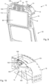
- the protective housing 143 is preferably arranged in a casing 15 fixedly attached to the front face 111 of the plate 11.
- the housing 15 preferably defines a hollow volume configured to receive the housing of the communication device.
- Such a casing 15 advantageously makes it possible to protect the protective housing 143 and therefore to maintain the positioning given to the protective housing. It makes it possible to avoid a disturbance in the orientation of the protective housing.
- the casing 15 is arranged above the upper part 523 of the backrest 52 of the seat.
- the casing 15 preferably comprises at least one opening 151, glazed or not, opposite the transparent glazed portion 144 of the protective housing 143, so as not to hinder the transmission/reception of the first and second signals between the two communication devices.
- Said opening of the casing 15 is arranged facing the remote communication device.
- said opening is facing the ceiling, on an upper part of the casing, as illustrated in the Figures 7 to 10 .
- the housing 15 can be made in one piece with the plate 11 or be an added part and fixed securely to the plate 11, for example by means of screws.
- the support 10 comprises two casings 15, arranged symmetrically on the plate 11, arranged above the upper part 523 of the backrest 52 of the seat.
- the two casings 15 have an external shape with a curvature substantially similar to the curvature of a portion of an upper part of the plate.
- the support 10 comprises a single communication device 14, which will be arranged in one of the two housings.
- a closing plate 152 is arranged so as to cover the opening 151 of said housing, as illustrated in the figure 2 .
- the choice of positioning the communication device 14 of the support in one or other of the housings 15 is linked to the positioning of the remote communication device.
- the seats arranged on the left wing side of the aircraft comprise a support 10 with a device of communication 14 preferably arranged in the right casing 15 of the support (ie the casing located on the aisle side).
- the seats arranged on the right wing side of the aircraft comprise a support 10 with a communication device 14 preferably arranged in the left casing of said support (ie the casing located on the aisle side).
- the support 10 may comprise a single casing 15, arranged above the upper part 523 of the backrest 52 and which has an external shape with a curvature substantially similar to the curvature of an upper part of the plate 11.
- the communication device 14 is advantageously connected to the connector 13 by a cable 16.
- the cable 16 runs along the structural frame 55 of the backrest. When the backrest is re-covered, the cable will be invisible.
- the cable 16 may have a visible portion extending beyond the rear face 112 of the plate 11 and the support 10, and terminating, at one end, called the first end, by the connector 13.
- the cable 13 is preferably connected to the protective housing 143 by complementary connection means 17, such as for example a USB port on the protective housing 14 and a USB connector at a second end of the cable 16, or vice versa.
- complementary connection means 17 such as for example a USB port on the protective housing 14 and a USB connector at a second end of the cable 16, or vice versa.
- the invention is not limited to USB connection means but may include other complementary connection means without this departing from the scope of the invention.
- the plate 11 of the support 10 comprises, at its rear face 112, an opening 113 configured to receive a tablet 90, or a screen, distributed by the airline. Said opening has a dimension adapted to said tablet.
- said opening for receiving the tablet is through, i.e. the opening is made throughout the thickness of the plate 11.
- Such a through opening configuration has the advantage of reducing the weight of the support.
- the plate 11 of the support 10 may comprise reversible holding elements 114 for the tablet in the opening 113 of the plate 11.
- the tablet may include supporting elements complementary to the supporting elements 114 of the plate.
- the holding elements 114 are magnets.
- the tablet 90 advantageously includes connection means complementary to the connector 13 of the support 10.
- the support 10 comprises two reversible fastening elements 18, each fastening element connecting a lower part of the plate 11 to the free end 123 of a tab coming to bear on a lateral portion 551 of the peripheral frame.
- fastening elements make it possible to ensure that the lower part of the plate 11 remains firmly pressed against the backrest 52, and does not move away, in particular due to vibrations in the aircraft.
- the fastening elements are flexible fastening elements such as textile strips with loops and hooks (of the Velcro® strip type), which adapt to the complex geometry and variations in thickness of the uncovered backrest.
- the support 10 comprises, in the thickness of the plate 11, at least one chimney 19 extending from said opening towards a periphery of the plate, preferably towards the upper part of the plate 11, as illustrated in the Figures 3 and 4 .
- the at least one chimney 19 makes it possible to ensure the circulation of air and the evacuation of hot air from the support 10.
- the plate and the casings are for example perforated, as illustrated in the Figures 2 to 10 .
- the plate 11, the housings 15 and the clamping mechanisms 12 of the support 10 are preferably made of an aluminum material.
- the invention is not limited to the aluminum material but can also be made of other materials, such as a composite material.
- the backrest 52 is re-covered.
- elastically compressible foam for example polyurethane
- a cover 70 of suitable dimensions, then advantageously covers the padding block 60 and the support 10 and is fixed in a conventional manner to the backrest 52, like existing covers, for example via textile strips with loops and hooks (such as Velcro® strips).
- the cover 70 advantageously completely covers the support 10, becoming invisible to the passengers.
- the cover 70 partially covers the support 10, only revealing said opening.
- the cover 70 is preferably made of a mesh fabric, in particular to allow the evacuation of hot air coming from the tablet 90, when it is installed in the opening 113 of the plate 11 of the support 10, and circulating in at least one chimney 19.
- the cover 70 preferably comprises a glazed area (not shown in the figures), facing the transparent glazed portion 144 of the protective housing 14 and the opening 151, glazed or not, of the casing 15, so as not to hinder the transmission/reception of the first and second signals between the two communication devices.
- Installing the seat cover ensures long-term use of the support. It reduces the risk of deterioration, vandalism, theft, and ensures visual harmony consistent with current seats not equipped with a screen or seats natively equipped with a screen.
- the seat located on the right on the figure 1 comprises the support 10 installed on the upper part of the backrest.
- the padding block 60 and the cover 70 (visible in dotted lines) adapted are shown there.
- the filling block and the cover of the backrest when the support is not installed.
- the support 10 forms an extension of the upper part 523 of the backrest 52 of the seat.
- the support has many advantages, described below in a non-exhaustive manner.
- the support when installed on the seat, has a small footprint, both in terms of height (so as not to hide the instructions), width (roughly the same width as the width of the seat) and depth (so as not to not obstruct the passage, particularly for safety reasons in the event of an evacuation).
- the holder when installed on the seat, in addition to providing access to entertainment data and/or internet data to the passenger located behind the seat, creates a headrest for the person sitting on the seat.
- the support advantageously allows passengers to have access to entertainment data and/or internet data, with their personal electronic equipment, in a specific privileged space, around their seat, via Li-Fi technology.
- a privileged space is understood to mean a unique and personal connection space allowing a passenger to receive and/or send internal and/or external data to the aircraft in a secure and personalized manner in a predetermined physical location, in this case their seat.
- the passenger benefits from a unique and personal connection space to receive and transmit data confidentially.
- the bracket allows you to equip a conventional seat not equipped with an IFE in-flight entertainment system, or to equip a seat equipped with an in-flight entertainment system with an obsolete screen, and also allows you to connect passengers' personal equipment.
- Equipping a seat with such a support may be of economic interest to the airline operating the aircraft rather than replacing all seats equipped with obsolete screens with new seats equipped with the latest generation screens.
- bracket The mounting of the bracket on the seat by means of a simple tightening does not damage the seat.
- bracket can be removed according to the operational needs of the aircraft to return to the original configuration, or future developments.
- Installation of the support by means of the adjustment mechanisms is quick and can adapt to different types and sizes of seats.
Landscapes
- Engineering & Computer Science (AREA)
- Aviation & Aerospace Engineering (AREA)
- Transportation (AREA)
- Mechanical Engineering (AREA)
- Fittings On The Vehicle Exterior For Carrying Loads, And Devices For Holding Or Mounting Articles (AREA)
- Telephone Set Structure (AREA)
- Chair Legs, Seat Parts, And Backrests (AREA)
Claims (10)
- Träger (10), der dazu bestimmt ist, reversibel an einem oberen Teil (523) einer Rückenlehne (52) ohne Bezug eines Sitzes (50) installiert zu werden, wobei der Träger ein Verbindungsstück (13) umfasst, das für die Verbindung mit einem elektronischen Gerät (90) bestimmt ist,dadurch gekennzeichnet, dass der Träger Folgendes umfasst:- eine Platte (11), die dazu bestimmt ist, ganz oder teilweise an einer hinteren Fläche (522) der Rückenlehne (52) anzuliegen,- drei Klemmmechanismen (12), wobei jeder Klemmmechanismus (12) ein Stützelement (121) und eine Klemmschraube (124) umfasst, die dazu bestimmt sind, mit der Platte (11) zusammenzuwirken, um einen Strukturrahmen (55) der Rückenlehne (52) zwischen dem Stützelement und der Platte festklemmen zu können,- eine Li-Fi-Technologie-Datenkommunikationsvorrichtung (14), die mit der Platte (11) verbunden ist,und dadurch, dass das Verbindungsstück (13) mit der Li-Fi-Technologie-Datenkommunikationsvorrichtung (14) über ein Kabel (16) verbunden ist.
- Träger (10) nach Anspruch 1, wobei das Stützelement (121) mindestens eines Klemmmechanismus (12) die Form einer länglichen Nase aufweist, die an einem freien Ende (123) eine Hakenform (126) aufweist.
- Träger (10) nach einem der vorhergehenden Ansprüche, wobei die Platte (11) eine Öffnung (113) umfasst, die für die Aufnahme eines elektronischen Geräts (90) bestimmt ist.
- Träger (10) nach Anspruch 3, wobei die Platte (11) reversible Halteelemente (114) für das elektronische Gerät (90) in der Öffnung (113) der Platte (11) umfasst.
- Träger (10) nach einem der Ansprüche 3 oder 4, der in einer Dicke der Platte (11) mindestens einen Schacht (19) umfasst, der sich von der Öffnung (113) in Richtung einer Peripherie der Platte erstreckt.
- Träger (10) nach einem der vorhergehenden Ansprüche, wobei die Datenkommunikationsvorrichtung (14) einen Sender (141) und einen Empfänger (142) umfasst, die in einem Schutzkasten (143) angeordnet sind, wobei der Schutzkasten einen verglasten Abschnitt (144) gegenüber dem Sender und dem Empfänger umfasst.
- Träger (10) nach dem vorhergehenden Anspruch, wobei der Schutzkasten (143) durch eine Gelenkverbindung (145) an der Platte (11) befestigt ist.
- Träger (10) nach einem der Ansprüche 6 bis 7, der ein Gehäuse (15) zum Aufnehmen der Datenkommunikationsvorrichtung (14) umfasst, wobei das Gehäuse fest an der Platte (11) befestigt ist.
- Träger (10) nach einem der Ansprüche 2 bis 8, der zwei reversible Befestigungselemente (18) umfasst, wobei jedes Befestigungselement einen unteren Teil der Platte (11) mit dem freien Ende (123) einer länglichen Nase verbindet.
- Sitz (50), der eine Rückenlehne (52) umfasst, die mit einem Träger (10) nach einem der Ansprüche 1 bis 9, mit einem Polsterblock (60) und mit einem Bezug (70), der den Polsterblock und den Träger bedeckt, ausgestattet ist, wobei der Bezug einen verglasten Bereich umfasst.
Applications Claiming Priority (2)
| Application Number | Priority Date | Filing Date | Title |
|---|---|---|---|
| FR1906362A FR3097178B1 (fr) | 2019-06-14 | 2019-06-14 | Support pour connecter un siège à un réseau de communication |
| PCT/EP2020/066037 WO2020249592A1 (fr) | 2019-06-14 | 2020-06-10 | Support pour connecter un siège à un réseau de communication |
Publications (2)
| Publication Number | Publication Date |
|---|---|
| EP3983263A1 EP3983263A1 (de) | 2022-04-20 |
| EP3983263B1 true EP3983263B1 (de) | 2024-10-23 |
Family
ID=68281604
Family Applications (1)
| Application Number | Title | Priority Date | Filing Date |
|---|---|---|---|
| EP20731090.5A Active EP3983263B1 (de) | 2019-06-14 | 2020-06-10 | Träger um einen sitz zu einem kommunikationsnetzwerk zu verbinden |
Country Status (6)
| Country | Link |
|---|---|
| US (1) | US11958607B2 (de) |
| EP (1) | EP3983263B1 (de) |
| JP (1) | JP7488838B2 (de) |
| CA (1) | CA3141369A1 (de) |
| FR (1) | FR3097178B1 (de) |
| WO (1) | WO2020249592A1 (de) |
Families Citing this family (6)
| Publication number | Priority date | Publication date | Assignee | Title |
|---|---|---|---|---|
| DE102019135393A1 (de) * | 2019-12-20 | 2021-06-24 | Recaro Aircraft Seating Gmbh & Co. Kg | Flugzeugsitzvorrichtung, Flugzeugsitz, Verfahren zur Herstellung der Flugzeugsitzvorrichtung und Baukastensystem |
| US12054262B2 (en) * | 2020-05-27 | 2024-08-06 | Adient Aerospace, Llc | Seat assembly and passenger seat arrangement |
| CN115848627A (zh) * | 2021-09-23 | 2023-03-28 | 空中客车(中国)企业管理服务有限公司 | 机上娱乐系统套件及其安装方法、乘客座椅以及飞行器 |
| US20240300648A1 (en) * | 2021-09-23 | 2024-09-12 | Airbus (China) Enterprise Management And Services Company Limited | In-flight entertainment system kit and installation method thereof, passenger seat and aircraft |
| FR3133572B1 (fr) * | 2022-03-17 | 2024-03-29 | Latelec | Siège équipé d’un module de communication de données selon la technologie Li-Fi |
| US12192193B2 (en) * | 2022-11-04 | 2025-01-07 | Capital One Services, Llc | Li-Fi-based location authentication |
Family Cites Families (14)
| Publication number | Priority date | Publication date | Assignee | Title |
|---|---|---|---|---|
| US6120155A (en) * | 1998-05-13 | 2000-09-19 | Marianne Brennan | Reflector device and system for viewing the rear seat of a vehicle |
| US6418010B1 (en) * | 2000-08-11 | 2002-07-09 | Gateway, Inc. | Convertible flat panel display hanging support |
| US20050011920A1 (en) * | 2003-07-17 | 2005-01-20 | Feng Chi Feng | Carrying case and display device combination for vehicle |
| EP1513129A1 (de) | 2003-09-02 | 2005-03-09 | Hexa-Chain Co., Ltd | Montagestruktur für eine Dünnfilmanzeigevorrichtung |
| US8403411B2 (en) * | 2003-12-15 | 2013-03-26 | Digecor, Inc. | Detachable seat mounted audio-visual entertainment system with locally storable, selectable, and updatable content |
| US20060032996A1 (en) * | 2004-08-11 | 2006-02-16 | Tai-Hsiung Wu | Fastening assembly for detachably mounting an onboard LCD between a headrest and a backrest |
| US20080023600A1 (en) | 2006-07-25 | 2008-01-31 | Perlman Marshal H | System and Method for Mounting User Interface Devices |
| JP5248088B2 (ja) | 2007-11-21 | 2013-07-31 | トヨタ紡織株式会社 | モニタパネルの取付け構造 |
| EP2253090A1 (de) | 2008-02-08 | 2010-11-24 | Panasonic Avionics Corporation | Optisches kommunikationssystem und verfahren zum verteilen von inhalt an bord einer mobilplattform während der reise |
| JP5544018B2 (ja) | 2009-10-02 | 2014-07-09 | パナソニック・アビオニクス・コーポレイション | 座席に統合ユーザインターフェースシステムを提供するためのシステム及び方法 |
| KR101292424B1 (ko) | 2011-11-21 | 2013-08-01 | 현대다이모스(주) | 차량용 시트 |
| US20140226983A1 (en) * | 2013-02-13 | 2014-08-14 | Teac Aerospace Technologies, Inc. | In-flight li-fi media distribution system |
| WO2016106385A1 (en) * | 2014-12-23 | 2016-06-30 | Reliant Worldwide Plastics, Llc | Thermoplastic composite retrofit panel assembly for personal entertainment device mount system |
| US20170282850A1 (en) * | 2016-04-04 | 2017-10-05 | Diana M. Friedman | Head restraint apparatus with expandable seat securing mechanisms |
-
2019
- 2019-06-14 FR FR1906362A patent/FR3097178B1/fr active Active
-
2020
- 2020-06-10 JP JP2021574230A patent/JP7488838B2/ja active Active
- 2020-06-10 WO PCT/EP2020/066037 patent/WO2020249592A1/fr not_active Ceased
- 2020-06-10 US US17/616,622 patent/US11958607B2/en active Active
- 2020-06-10 CA CA3141369A patent/CA3141369A1/fr active Pending
- 2020-06-10 EP EP20731090.5A patent/EP3983263B1/de active Active
Also Published As
| Publication number | Publication date |
|---|---|
| CA3141369A1 (fr) | 2020-12-17 |
| US11958607B2 (en) | 2024-04-16 |
| US20220227492A1 (en) | 2022-07-21 |
| WO2020249592A1 (fr) | 2020-12-17 |
| JP2022536391A (ja) | 2022-08-15 |
| JP7488838B2 (ja) | 2024-05-22 |
| FR3097178B1 (fr) | 2021-06-25 |
| FR3097178A1 (fr) | 2020-12-18 |
| EP3983263A1 (de) | 2022-04-20 |
Similar Documents
| Publication | Publication Date | Title |
|---|---|---|
| EP3983263B1 (de) | Träger um einen sitz zu einem kommunikationsnetzwerk zu verbinden | |
| EP1479194B1 (de) | Lokales netzwerk zum austausch von daten zwischen mobilen personalcomputern für flugzeugpassagiere | |
| FR3094348A1 (fr) | Module de caméra et système de surveillance d’une cabine des passagers d’un aéronef ainsi qu’aéronef. | |
| EP1442926A1 (de) | Fahrzeugsitzüberzug mit einer tragbaren Videoanlage. | |
| EP3328059B1 (de) | Kameravorrichtung eines kraftfahrzeugs, und montagemethode | |
| FR3079609A1 (fr) | Calculateur amovible pour aeronef | |
| FR2907758A1 (fr) | Dispositif d'integration d'un ordinateur portable dans un cockpit d'avion | |
| EP2620365B1 (de) | Vorrichtung zur Stromversorgung von in den Boden einer Luftfahrzeugkabine integrierten Geräten | |
| CA2041617A1 (fr) | Augmentation du champ vertical d'un systme de projection collimate grand champ horizontal | |
| EP3804280B1 (de) | System zur übertragung über signale vom typ li-fi | |
| FR2881841A1 (fr) | Systeme integre optronique et radar pour avion de combat | |
| CA2937510C (fr) | Dispositif de communication d'une cabine d'aeronef | |
| FR3097174A1 (fr) | Housse pour siège équipé d’un dispositif de communication de données selon la technologie Li-Fi | |
| FR2998386A1 (fr) | Systeme de preparation de mission, notamment pour aeronef comportant une station d'accueil | |
| EP4494278B1 (de) | Sitz mit einem datenkommunikationsmodul nach li-fi-technologie | |
| FR3120480A1 (fr) | Procédés et kits pour modifier un hélicoptère | |
| FR2942434A1 (fr) | Console operateur legere pour systeme embarque dans un vehicule | |
| FR2986773A1 (fr) | Vehicule automobile a usage special comprenant une structure de support d'equipements specifiques, et structure de support correspondante | |
| EP3834127B1 (de) | Verfahren zum erfassen und senden eines mit mindestens einer kontextinformation erweiterten videos und vorrichtung zur implementierung davon | |
| EP3577727B1 (de) | Impedanzanpassende verbindungsvorrichtung | |
| FR3106737A1 (fr) | Plateau de service et ensemble comprenant un tel plateau de service | |
| FR2850513A1 (fr) | Installation video portable comprenant une console electronique, genre lecteur video ou console de jeu, et un ecran independant associe | |
| FR2856209A1 (fr) | Systeme de communication entre deux points d'emport d'un aeronef | |
| FR3010579A1 (fr) | Dispositif de visualisation comportant une connexion electrique et mecanique par baionnette | |
| FR2960665A1 (fr) | Systeme de transmission de signal destine a etre embarque dans un vehicule |
Legal Events
| Date | Code | Title | Description |
|---|---|---|---|
| STAA | Information on the status of an ep patent application or granted ep patent |
Free format text: STATUS: UNKNOWN |
|
| STAA | Information on the status of an ep patent application or granted ep patent |
Free format text: STATUS: THE INTERNATIONAL PUBLICATION HAS BEEN MADE |
|
| PUAI | Public reference made under article 153(3) epc to a published international application that has entered the european phase |
Free format text: ORIGINAL CODE: 0009012 |
|
| STAA | Information on the status of an ep patent application or granted ep patent |
Free format text: STATUS: REQUEST FOR EXAMINATION WAS MADE |
|
| 17P | Request for examination filed |
Effective date: 20220111 |
|
| AK | Designated contracting states |
Kind code of ref document: A1 Designated state(s): AL AT BE BG CH CY CZ DE DK EE ES FI FR GB GR HR HU IE IS IT LI LT LU LV MC MK MT NL NO PL PT RO RS SE SI SK SM TR |
|
| STAA | Information on the status of an ep patent application or granted ep patent |
Free format text: STATUS: EXAMINATION IS IN PROGRESS |
|
| 17Q | First examination report despatched |
Effective date: 20220623 |
|
| DAV | Request for validation of the european patent (deleted) | ||
| DAX | Request for extension of the european patent (deleted) | ||
| GRAP | Despatch of communication of intention to grant a patent |
Free format text: ORIGINAL CODE: EPIDOSNIGR1 |
|
| STAA | Information on the status of an ep patent application or granted ep patent |
Free format text: STATUS: GRANT OF PATENT IS INTENDED |
|
| INTG | Intention to grant announced |
Effective date: 20240529 |
|
| GRAS | Grant fee paid |
Free format text: ORIGINAL CODE: EPIDOSNIGR3 |
|
| GRAA | (expected) grant |
Free format text: ORIGINAL CODE: 0009210 |
|
| STAA | Information on the status of an ep patent application or granted ep patent |
Free format text: STATUS: THE PATENT HAS BEEN GRANTED |
|
| AK | Designated contracting states |
Kind code of ref document: B1 Designated state(s): AL AT BE BG CH CY CZ DE DK EE ES FI FR GB GR HR HU IE IS IT LI LT LU LV MC MK MT NL NO PL PT RO RS SE SI SK SM TR |
|
| REG | Reference to a national code |
Ref country code: GB Ref legal event code: FG4D Free format text: NOT ENGLISH |
|
| REG | Reference to a national code |
Ref country code: CH Ref legal event code: EP |
|
| REG | Reference to a national code |
Ref country code: DE Ref legal event code: R096 Ref document number: 602020039876 Country of ref document: DE |
|
| REG | Reference to a national code |
Ref country code: IE Ref legal event code: FG4D Free format text: LANGUAGE OF EP DOCUMENT: FRENCH |
|
| REG | Reference to a national code |
Ref country code: LT Ref legal event code: MG9D |
|
| REG | Reference to a national code |
Ref country code: NL Ref legal event code: MP Effective date: 20241023 |
|
| REG | Reference to a national code |
Ref country code: AT Ref legal event code: MK05 Ref document number: 1734587 Country of ref document: AT Kind code of ref document: T Effective date: 20241023 |
|
| PG25 | Lapsed in a contracting state [announced via postgrant information from national office to epo] |
Ref country code: NL Free format text: LAPSE BECAUSE OF FAILURE TO SUBMIT A TRANSLATION OF THE DESCRIPTION OR TO PAY THE FEE WITHIN THE PRESCRIBED TIME-LIMIT Effective date: 20241023 |
|
| PG25 | Lapsed in a contracting state [announced via postgrant information from national office to epo] |
Ref country code: NL Free format text: LAPSE BECAUSE OF FAILURE TO SUBMIT A TRANSLATION OF THE DESCRIPTION OR TO PAY THE FEE WITHIN THE PRESCRIBED TIME-LIMIT Effective date: 20241023 |
|
| PG25 | Lapsed in a contracting state [announced via postgrant information from national office to epo] |
Ref country code: IS Free format text: LAPSE BECAUSE OF FAILURE TO SUBMIT A TRANSLATION OF THE DESCRIPTION OR TO PAY THE FEE WITHIN THE PRESCRIBED TIME-LIMIT Effective date: 20250223 Ref country code: HR Free format text: LAPSE BECAUSE OF FAILURE TO SUBMIT A TRANSLATION OF THE DESCRIPTION OR TO PAY THE FEE WITHIN THE PRESCRIBED TIME-LIMIT Effective date: 20241023 Ref country code: PT Free format text: LAPSE BECAUSE OF FAILURE TO SUBMIT A TRANSLATION OF THE DESCRIPTION OR TO PAY THE FEE WITHIN THE PRESCRIBED TIME-LIMIT Effective date: 20250224 |
|
| PG25 | Lapsed in a contracting state [announced via postgrant information from national office to epo] |
Ref country code: FI Free format text: LAPSE BECAUSE OF FAILURE TO SUBMIT A TRANSLATION OF THE DESCRIPTION OR TO PAY THE FEE WITHIN THE PRESCRIBED TIME-LIMIT Effective date: 20241023 |
|
| PG25 | Lapsed in a contracting state [announced via postgrant information from national office to epo] |
Ref country code: BG Free format text: LAPSE BECAUSE OF FAILURE TO SUBMIT A TRANSLATION OF THE DESCRIPTION OR TO PAY THE FEE WITHIN THE PRESCRIBED TIME-LIMIT Effective date: 20241023 |
|
| PG25 | Lapsed in a contracting state [announced via postgrant information from national office to epo] |
Ref country code: ES Free format text: LAPSE BECAUSE OF FAILURE TO SUBMIT A TRANSLATION OF THE DESCRIPTION OR TO PAY THE FEE WITHIN THE PRESCRIBED TIME-LIMIT Effective date: 20241023 |
|
| PG25 | Lapsed in a contracting state [announced via postgrant information from national office to epo] |
Ref country code: NO Free format text: LAPSE BECAUSE OF FAILURE TO SUBMIT A TRANSLATION OF THE DESCRIPTION OR TO PAY THE FEE WITHIN THE PRESCRIBED TIME-LIMIT Effective date: 20250123 |
|
| PG25 | Lapsed in a contracting state [announced via postgrant information from national office to epo] |
Ref country code: AT Free format text: LAPSE BECAUSE OF FAILURE TO SUBMIT A TRANSLATION OF THE DESCRIPTION OR TO PAY THE FEE WITHIN THE PRESCRIBED TIME-LIMIT Effective date: 20241023 Ref country code: LV Free format text: LAPSE BECAUSE OF FAILURE TO SUBMIT A TRANSLATION OF THE DESCRIPTION OR TO PAY THE FEE WITHIN THE PRESCRIBED TIME-LIMIT Effective date: 20241023 Ref country code: GR Free format text: LAPSE BECAUSE OF FAILURE TO SUBMIT A TRANSLATION OF THE DESCRIPTION OR TO PAY THE FEE WITHIN THE PRESCRIBED TIME-LIMIT Effective date: 20250124 |
|
| PG25 | Lapsed in a contracting state [announced via postgrant information from national office to epo] |
Ref country code: PL Free format text: LAPSE BECAUSE OF FAILURE TO SUBMIT A TRANSLATION OF THE DESCRIPTION OR TO PAY THE FEE WITHIN THE PRESCRIBED TIME-LIMIT Effective date: 20241023 |
|
| PG25 | Lapsed in a contracting state [announced via postgrant information from national office to epo] |
Ref country code: RS Free format text: LAPSE BECAUSE OF FAILURE TO SUBMIT A TRANSLATION OF THE DESCRIPTION OR TO PAY THE FEE WITHIN THE PRESCRIBED TIME-LIMIT Effective date: 20250123 |
|
| PG25 | Lapsed in a contracting state [announced via postgrant information from national office to epo] |
Ref country code: SM Free format text: LAPSE BECAUSE OF FAILURE TO SUBMIT A TRANSLATION OF THE DESCRIPTION OR TO PAY THE FEE WITHIN THE PRESCRIBED TIME-LIMIT Effective date: 20241023 |
|
| PGFP | Annual fee paid to national office [announced via postgrant information from national office to epo] |
Ref country code: DE Payment date: 20250627 Year of fee payment: 6 |
|
| PG25 | Lapsed in a contracting state [announced via postgrant information from national office to epo] |
Ref country code: DK Free format text: LAPSE BECAUSE OF FAILURE TO SUBMIT A TRANSLATION OF THE DESCRIPTION OR TO PAY THE FEE WITHIN THE PRESCRIBED TIME-LIMIT Effective date: 20241023 |
|
| PGFP | Annual fee paid to national office [announced via postgrant information from national office to epo] |
Ref country code: GB Payment date: 20250630 Year of fee payment: 6 |
|
| PG25 | Lapsed in a contracting state [announced via postgrant information from national office to epo] |
Ref country code: EE Free format text: LAPSE BECAUSE OF FAILURE TO SUBMIT A TRANSLATION OF THE DESCRIPTION OR TO PAY THE FEE WITHIN THE PRESCRIBED TIME-LIMIT Effective date: 20241023 |
|
| PGFP | Annual fee paid to national office [announced via postgrant information from national office to epo] |
Ref country code: FR Payment date: 20250619 Year of fee payment: 6 |
|
| PG25 | Lapsed in a contracting state [announced via postgrant information from national office to epo] |
Ref country code: RO Free format text: LAPSE BECAUSE OF FAILURE TO SUBMIT A TRANSLATION OF THE DESCRIPTION OR TO PAY THE FEE WITHIN THE PRESCRIBED TIME-LIMIT Effective date: 20241023 |
|
| REG | Reference to a national code |
Ref country code: DE Ref legal event code: R097 Ref document number: 602020039876 Country of ref document: DE |
|
| PG25 | Lapsed in a contracting state [announced via postgrant information from national office to epo] |
Ref country code: SK Free format text: LAPSE BECAUSE OF FAILURE TO SUBMIT A TRANSLATION OF THE DESCRIPTION OR TO PAY THE FEE WITHIN THE PRESCRIBED TIME-LIMIT Effective date: 20241023 |
|
| PG25 | Lapsed in a contracting state [announced via postgrant information from national office to epo] |
Ref country code: CZ Free format text: LAPSE BECAUSE OF FAILURE TO SUBMIT A TRANSLATION OF THE DESCRIPTION OR TO PAY THE FEE WITHIN THE PRESCRIBED TIME-LIMIT Effective date: 20241023 |
|
| PG25 | Lapsed in a contracting state [announced via postgrant information from national office to epo] |
Ref country code: IT Free format text: LAPSE BECAUSE OF FAILURE TO SUBMIT A TRANSLATION OF THE DESCRIPTION OR TO PAY THE FEE WITHIN THE PRESCRIBED TIME-LIMIT Effective date: 20241023 |
|
| PLBE | No opposition filed within time limit |
Free format text: ORIGINAL CODE: 0009261 |
|
| STAA | Information on the status of an ep patent application or granted ep patent |
Free format text: STATUS: NO OPPOSITION FILED WITHIN TIME LIMIT |
|
| PG25 | Lapsed in a contracting state [announced via postgrant information from national office to epo] |
Ref country code: SE Free format text: LAPSE BECAUSE OF FAILURE TO SUBMIT A TRANSLATION OF THE DESCRIPTION OR TO PAY THE FEE WITHIN THE PRESCRIBED TIME-LIMIT Effective date: 20241023 |
|
| 26N | No opposition filed |
Effective date: 20250724 |
|
| REG | Reference to a national code |
Ref country code: CH Ref legal event code: H13 Free format text: ST27 STATUS EVENT CODE: U-0-0-H10-H13 (AS PROVIDED BY THE NATIONAL OFFICE) Effective date: 20260127 |
|
| PG25 | Lapsed in a contracting state [announced via postgrant information from national office to epo] |
Ref country code: MC Free format text: LAPSE BECAUSE OF FAILURE TO SUBMIT A TRANSLATION OF THE DESCRIPTION OR TO PAY THE FEE WITHIN THE PRESCRIBED TIME-LIMIT Effective date: 20241023 |
|
| PG25 | Lapsed in a contracting state [announced via postgrant information from national office to epo] |
Ref country code: LU Free format text: LAPSE BECAUSE OF NON-PAYMENT OF DUE FEES Effective date: 20250610 |
|
| REG | Reference to a national code |
Ref country code: BE Ref legal event code: MM Effective date: 20250630 |
|
| PG25 | Lapsed in a contracting state [announced via postgrant information from national office to epo] |
Ref country code: IE Free format text: LAPSE BECAUSE OF NON-PAYMENT OF DUE FEES Effective date: 20250610 |
|
| PG25 | Lapsed in a contracting state [announced via postgrant information from national office to epo] |
Ref country code: BE Free format text: LAPSE BECAUSE OF NON-PAYMENT OF DUE FEES Effective date: 20250630 |
|
| PG25 | Lapsed in a contracting state [announced via postgrant information from national office to epo] |
Ref country code: CH Free format text: LAPSE BECAUSE OF NON-PAYMENT OF DUE FEES Effective date: 20250630 |