EP3982527A1 - A dc/dc converter and a method for operating a dc/dc converter - Google Patents
A dc/dc converter and a method for operating a dc/dc converter Download PDFInfo
- Publication number
- EP3982527A1 EP3982527A1 EP20200583.1A EP20200583A EP3982527A1 EP 3982527 A1 EP3982527 A1 EP 3982527A1 EP 20200583 A EP20200583 A EP 20200583A EP 3982527 A1 EP3982527 A1 EP 3982527A1
- Authority
- EP
- European Patent Office
- Prior art keywords
- converter
- operation mode
- converter stage
- coupling circuit
- power transfer
- Prior art date
- Legal status (The legal status is an assumption and is not a legal conclusion. Google has not performed a legal analysis and makes no representation as to the accuracy of the status listed.)
- Pending
Links
Images


Classifications
-
- H—ELECTRICITY
- H02—GENERATION; CONVERSION OR DISTRIBUTION OF ELECTRIC POWER
- H02M—APPARATUS FOR CONVERSION BETWEEN AC AND AC, BETWEEN AC AND DC, OR BETWEEN DC AND DC, AND FOR USE WITH MAINS OR SIMILAR POWER SUPPLY SYSTEMS; CONVERSION OF DC OR AC INPUT POWER INTO SURGE OUTPUT POWER; CONTROL OR REGULATION THEREOF
- H02M3/00—Conversion of DC power input into DC power output
- H02M3/22—Conversion of DC power input into DC power output with intermediate conversion into AC
- H02M3/24—Conversion of DC power input into DC power output with intermediate conversion into AC by static converters
- H02M3/28—Conversion of DC power input into DC power output with intermediate conversion into AC by static converters using discharge tubes with control electrode or semiconductor devices with control electrode to produce the intermediate AC
- H02M3/325—Conversion of DC power input into DC power output with intermediate conversion into AC by static converters using discharge tubes with control electrode or semiconductor devices with control electrode to produce the intermediate AC using devices of a triode or a transistor type requiring continuous application of a control signal
- H02M3/335—Conversion of DC power input into DC power output with intermediate conversion into AC by static converters using discharge tubes with control electrode or semiconductor devices with control electrode to produce the intermediate AC using devices of a triode or a transistor type requiring continuous application of a control signal using semiconductor devices only
- H02M3/33569—Conversion of DC power input into DC power output with intermediate conversion into AC by static converters using discharge tubes with control electrode or semiconductor devices with control electrode to produce the intermediate AC using devices of a triode or a transistor type requiring continuous application of a control signal using semiconductor devices only having several active switching elements
- H02M3/33576—Conversion of DC power input into DC power output with intermediate conversion into AC by static converters using discharge tubes with control electrode or semiconductor devices with control electrode to produce the intermediate AC using devices of a triode or a transistor type requiring continuous application of a control signal using semiconductor devices only having several active switching elements having at least one active switching element at the secondary side of an isolation transformer
- H02M3/33584—Bidirectional converters
-
- H—ELECTRICITY
- H02—GENERATION; CONVERSION OR DISTRIBUTION OF ELECTRIC POWER
- H02M—APPARATUS FOR CONVERSION BETWEEN AC AND AC, BETWEEN AC AND DC, OR BETWEEN DC AND DC, AND FOR USE WITH MAINS OR SIMILAR POWER SUPPLY SYSTEMS; CONVERSION OF DC OR AC INPUT POWER INTO SURGE OUTPUT POWER; CONTROL OR REGULATION THEREOF
- H02M1/00—Details of apparatus for conversion
- H02M1/0003—Details of control, feedback or regulation circuits
- H02M1/0009—Devices or circuits for detecting current in a converter
-
- H—ELECTRICITY
- H02—GENERATION; CONVERSION OR DISTRIBUTION OF ELECTRIC POWER
- H02M—APPARATUS FOR CONVERSION BETWEEN AC AND AC, BETWEEN AC AND DC, OR BETWEEN DC AND DC, AND FOR USE WITH MAINS OR SIMILAR POWER SUPPLY SYSTEMS; CONVERSION OF DC OR AC INPUT POWER INTO SURGE OUTPUT POWER; CONTROL OR REGULATION THEREOF
- H02M1/00—Details of apparatus for conversion
- H02M1/0048—Circuits or arrangements for reducing losses
- H02M1/0054—Transistor switching losses
- H02M1/0058—Transistor switching losses by employing soft switching techniques, i.e. commutation of transistors when applied voltage is zero or when current flow is zero
-
- Y—GENERAL TAGGING OF NEW TECHNOLOGICAL DEVELOPMENTS; GENERAL TAGGING OF CROSS-SECTIONAL TECHNOLOGIES SPANNING OVER SEVERAL SECTIONS OF THE IPC; TECHNICAL SUBJECTS COVERED BY FORMER USPC CROSS-REFERENCE ART COLLECTIONS [XRACs] AND DIGESTS
- Y02—TECHNOLOGIES OR APPLICATIONS FOR MITIGATION OR ADAPTATION AGAINST CLIMATE CHANGE
- Y02B—CLIMATE CHANGE MITIGATION TECHNOLOGIES RELATED TO BUILDINGS, e.g. HOUSING, HOUSE APPLIANCES OR RELATED END-USER APPLICATIONS
- Y02B70/00—Technologies for an efficient end-user side electric power management and consumption
- Y02B70/10—Technologies improving the efficiency by using switched-mode power supplies [SMPS], i.e. efficient power electronics conversion e.g. power factor correction or reduction of losses in power supplies or efficient standby modes
Definitions
- the present invention relates to bidirectional DC/DC converters, particularly to control methods for an operation of DC/DC converters that leads to a natural power transfer in the correct direction.
- DC grids are becoming a conceivable solution for small to a large-scale power distribution.
- a DC/DC conversion is used to change the voltage level of network subsystems further preferably providing a galvanic isolation between the DC subsystems.
- DC power distribution networks are already common in specialized applications, such as railway and marine power distribution networks or high capacity data server facilities.
- DC transformers power electronics DC/DC converters (serving as DC transformers) which are required for providing isolated interconnection between the DC grid subsystems.
- the requirements for DC transformers resemble that of conventional and simple (non-solid-state) AC transformers and basically allow a natural transfer of power according to the state of the connected subsystem grids.
- the idea here is that the DC transformer should behave as a conventional AC transformer (two windings and core).Substantially, the DC transformers need to exhibit a high efficiency, a galvanic isolation, an unrestricted voltage conversion, and the possibility of a bidirectional power transfer between both sides of the DC/DC converter.
- DC grids of such a power distribution network may be interconnected using an open-loop operated LLC resonant converter serving as a DC transformer.
- LLC resonant converter has a resonant tank consisting at least of two inductors (that might be integrated in a transformer) and one capacitor and is switched with a constant 50% duty cycle with a switching frequency near or at a resonant frequency of the resonant tank. According to the power transfer direction, only one of the converter power stages is actively switched, while the other one is set inactive or operated to act as a passive rectifier.
- the LLC resonant converter topology can generally be extended with a medium frequency transformer to satisfy basic requirements, such as a load-independent stiff voltage ratio and a galvanic isolation.
- LLC resonant converter topology One main benefit of such an LLC resonant converter topology is that it naturally transfers power without any external setpoints and without any control loops.
- both sides of the converter have to be designed as an active converter stage that is capable of both passive rectification and active inverting.
- the LLC resonant converter has two converter stages coupled by means of a resonant tank.
- the converter stages are formed by active semiconductor devices forming a circuitry according to a voltage source topology.
- the passive rectification is commonly achieved by intrinsic antiparallel diodes of the voltage source topologies of the used semiconductor devices.
- one of the converter stages has to be switched as an active inverter while the other one acts as a passive rectifier. Therefore, when the power transfer direction has to be changed, the converter stage operated as an active inverter will be switched off to obtain a passive rectification while the converter stage operated as a passive rectifier is controlled to operate as an active inverter.
- the problem of deciding the correction operation power transfer direction is handled by a power flow controller which provides the information about its setpoint and accordingly controls the operation of the converter stages, as e.g. known from J. Huang et al., "Implementation of bidirectional resonant DC transformer in hybrid AC/DC micro-grid," IEEE Transactions on Smart Grid, vol. 10, no. 2, pp. 1532-1542, 2019 .
- the required power direction is well known and thus, the correct operation direction of the DC converter can be determined easily.
- a problem may occur when the connected power-converter stage cannot follow its setpoint correctly and the operation direction is decided wrongly.
- the method is only applicable when the setpoints are externally determined and well known, which is not the case for many applications.
- a DC/DC converter for transferring an active power between two DC subsystems, comprising:
- the AC coupling circuit may include a resonant tank, wherein particularly the AC coupling circuit includes a medium or high frequency operated transformer.
- DC converters of the LLC type are operated in open loop with a constant switching frequency and therefore no external power setpoint may be given.
- the power transfer direction which determines which one of the converter stages has to be actively switched and operated as an active inverter needs to be decided internally.
- Above DC/DC converter decides about the power flow direction by observing the amount of power transfer over the AC coupling circuit.
- control unit may be configured either in a first operation mode to actively operate the first converter stage and not to operate the second converter stage so that it acts as a rectifier, or, in a second operation mode, to actively operate the second converter stage and not to operate the first converter stage so that it acts as a rectifier.
- control unit may be configured to switch from the first operation mode to the second operation mode if a power transfer flow is from the second converter stage into the AC coupling circuit and/or to switch from the second operation mode to the first operation mode if a power transfer flow is from the first converter stage into the AC coupling circuit.
- control unit is configured to switch from the first operation mode to the second operation mode if a power transfer flow from the second converter stage into the AC coupling circuit is below a given second threshold and/or to switch from the second operation mode to the first operation mode if a power transfer flow from the first converter stage into the AC coupling circuit is below a given first threshold .
- One possible and efficient way to observe the AC power transfer through the AC coupling circuit is by observing the current flow through the AC coupling circuit.
- a first current sensor between the first converter stage and the AC coupling circuit may be provided to measure a first absolute value of a peak current amplitude flowing into the AC coupling circuit and/or wherein a second current sensor between the second converter stage and the AC coupling circuit is provided to measure a second absolute value of a peak current amplitude flowing into the AC coupling circuit.
- the control unit may be configured to switch from the first operation mode to the second operation mode if a second absolute value of the peak current amplitude is below a given second peak current threshold value and/or to switch from the second operation mode to the first operation mode if a first absolute value of the peak current amplitude is below a given first peak current threshold value.
- control unit may include a state machine.
- a method for operating a DC/DC converter for transferring DC power between two DC subsystems comprising:
- the first converter stage in a first operation mode, may be actively operated and the second converter stage may be not operated so that it acts as a rectifier, and, in a second operation mode, the second converter stage may be actively operated and the first converter stage may be not operated so that it acts as a rectifier, wherein it is switched from the first operation mode to the second operation mode if a power transfer flow from the second converter stage into the AC coupling circuit is below a given second threshold and/or it is switched from the second operation mode to the first operation mode if a power transfer flow from the first converter stage into the AC coupling circuit is below a given first threshold .
- Figure 1 shows a first converter stage 3 and a second converter stage 4 which are coupled via the AC coupling unit 2.
- the first converter stage 3 has a first terminal 31 to be connected to a first DC subsystem 5.
- a second terminal 32 of the first converter stage 3 is coupled to the AC coupling unit 2.
- the second converter stage 4 substantially is configured similar.
- the second converter stage has a first terminal 41 to be connected to a second DC subsystem 6.
- a second terminal 42 of the first converter stage 3 is coupled to the AC coupling unit 2.
- the first and second converter stages 3, 4 are configured to be actively operated to act as an active converter, thereby transforming a DC voltage at the respective first terminal 31, 41 to an AC voltage at the respective second terminal 32, 42.
- the converter stages 3, 4 are not actively operated they act as passive rectifiers.
- the DC/DC converter from Figure 1 is shown in more detail in an exemplary configuration.
- the exemplary configuration as shown in Figure 2 , has the first and second converter stages 3, 4 configured as H-bridges with semiconductor devices 7, such as MOSFETs, IGBTs, GTOs, IGCTs or the like.
- semiconductor devices 7 include an intrinsic diode which will become effective in case the semiconductor devices of the respective converter stage 3, 4 are not actively operated thereby rendering the converter stage to act as a passive rectifier.
- the diodes form a diode bridge with the known rectifying characteristics.
- an input DC voltage u dc,1 is applied onto the DC side of the first converter stage 3 which results in an input DC current i dc,1 .
- Power transfer is from the first converter stage 3 to the second converter stage 4 which results in an output DC voltage u dc,2 at the output formed by the second converter stage 4 with an output DC current i dc,2 .
- an input DC voltage u dc,2 is applied onto the DC side of the second converter stage 4 which results in an input DC current i dc,2 .
- Power transfer is from the second converter stage 4 to the first converter stage 3 which results in an output DC voltage u dc,1 at the output formed by the first converter stage 3 with an output DC current i dc,1 .
- DC voltage variations may be buffered by the capacities C dc,1 and C dc,2 .
- FIG. 3a Further embodiments of the configuration of converter stages are shown in the circuits of Figures 3a to 3c wherein the configuration of converter stages 3, 4 may include a half-bridge configuration ( Figure 3a ), a half-bridge configuration with a center tap capacitor ( Figure 3b ) and a three-level voltage source converter ( Figure 3c ) as known in the art.
- the invention is applicable for any kind of power electronics converter stage which may generate at least two voltage levels.
- the AC coupling unit 2 is configured as a resonant tank.
- the resonant tank is shown as a combination of one or more capacitors C and one or more inductivities L1, L2, L3... and might include a medium frequency transformer 8 for a voltage level transformation.
- the resonant tank at least has one series capacitor C and a series inductance L1 as well as a parallel inductance L2.
- FIG. 4a to 4h Other configurations of the LLC resonant tank are shown in Figs. 4a to 4h wherein the configurations of Fig. 4e to 4h include a transformer while the configurations of Figs. 4a to 4d directly interconnecting the converter stages 3, 4 without any galvanic insulation.
- the medium frequency transformer 8 defines the voltage ratio between the first DC subsystem 5 and the second DC subsystem 6
- a control unit 10 is provided which is connected to the converter stages 3, 4 to operate the converter stages 3, 4 as an active inverter or as a passive rectifier selectively.
- the semiconductor devices are switched concurrently with a given switching frequency fs at a duty cycle of 50% as known in the art.
- the result is an AC voltage at the respective second converter terminal 32, 42.
- the switching frequency is selected to be at or close to the resonant frequency of the resonant tank 2.
- a first current sensor 33 may be provided at the second terminal 32 of the first converter stage 3 and a second current sensor 43 may be provided at the second terminal 42 of the second converter stage 4.
- the current sensors 33, 43 may be configured to detect the current amplitude.
- An easy method to obtain the current amplitude is to use a current to voltage converter rectifying the sensor voltage and deriving the peak voltage therefrom.
- Another option can be to measure the peak current at a timing of one fourth and/or three fourths of the switching period after the start time of the switching period since the current characteristics is commonly sinusoidal starting with a current of 0 at the start time of each switching period.
- control unit 10 checks the direction of the power transfer flow through the resonant tank 2 and determines the operation mode of the converter stages 3, 4 correspondingly.
- the control unit 10 may be operated as a state machine which determines within one switching period 1 fs which substantially corresponds to the resonance frequency of the resonant tank 2 about the peak value of the current flow into the rectifier side.
- the DC/DC converter 1 is therefore operated in a two-mode operation wherein one of the converter stages 3, 4 is switched actively to act as an inverter applying an AC voltage its second terminal while the correspondingly other converter stage 4, 3 is operated as a passive rectifier.
- stage S1 With a mode of operation where the first converter stage 3 is actively operated as an inverter, while the second converter stage 4 is passively operated as a rectifier.
- an absolute value of the peak current I 2 into the resonant tank 2 is detected on the rectifier side (second converter stage 4) by the second current sensor 43 and compared to a second predetermined peak current threshold value I th2 .
- the second peak current threshold value I th2 for the peak currents are set to ensure that the offsets of the current sensors 33, 43 cannot cause an assumption of a non-existent power flow. This can be achieved by selecting the peak current threshold values with a sufficient margin from a worst case offset and a noise of the current sensors 33, 43 and the utilized analogue digital converters.
- stage S2 a switching of the operation mode of the DC/DC converter is performed by transferring to stage S2. Accordingly, the first converter stage 3 is switched passive, while the second converter stage 4 changes its mode to an active inverter. If it is determined that the absolute value of the second peak current amplitude I 2 is not below the provided second peak current threshold value I th2 , the stage S1 is maintained.
- stage S2 for the next switching period, an absolute value of the peak current I 1 into the resonant tank 2 is detected on the rectifier side (first converter stage 3) by the first current sensor 33 and compared to a first predetermined peak current threshold value I th1 .
- the stage S2 is maintained.
- Using the current sensor which is related to the converter stage which acts as a rectifier has the advantage that only the peak current value indicating the current amplitude of the respective resonance is sufficient for the decision about the power transfer direction.
- the first and second peak current threshold value I th1 , I th2 may be basically the same. However, if a medium frequency transformer 8 with a winding ratio different to 1 is used the peak current threshold values may be preset with the same ratio.
- the operation mode as described above is particularly not sensitive to gain errors, since these only virtually change the peak current threshold value, thus increase or decrease the power range in which the alternating operation is present. Therefore, not capturing the measured current value exactly at the peak can viewed as a small gain error and thus is not critical either.
- the peak current amplitude I 1 (i r,1 in Figure 2 ), I 2 (i r,2 in Figure 2 ) is detected once per switching period, however, the current amplitude can be detected two times per switching period related to the rising and falling edges to improve the response time of the DC/DC converter.
- the sensor offset can be corrected from drifting, since the measured current is an AC current so that a mean value of known peak values can be used to compensate the sensor drift.
- some measurement redundancy can be achieved by removing a predicted magnetizing current value from the measured current of the active bridge.
- the peak resonant current can also be estimated by measuring the change of the corresponding resonant capacitor voltage at the rising and falling edges. Then, the switchover current peak thresholds values may be set according to the voltage sensor noise to ensure the required operation direction is estimated correctly.
Landscapes
- Engineering & Computer Science (AREA)
- Power Engineering (AREA)
- Dc-Dc Converters (AREA)
Abstract
Description
- The present invention relates to bidirectional DC/DC converters, particularly to control methods for an operation of DC/DC converters that leads to a natural power transfer in the correct direction.
- Due to the numerous disadvantages of the AC grid network and in view of the dropping costs for power electronic converters, DC grids are becoming a conceivable solution for small to a large-scale power distribution. For DC power distribution networks, a DC/DC conversion is used to change the voltage level of network subsystems further preferably providing a galvanic isolation between the DC subsystems. Nowadays, DC power distribution networks are already common in specialized applications, such as railway and marine power distribution networks or high capacity data server facilities.
- A key factor of large-scale DC grids is the general availability of power electronics DC/DC converters (serving as DC transformers) which are required for providing isolated interconnection between the DC grid subsystems. The requirements for DC transformers resemble that of conventional and simple (non-solid-state) AC transformers and basically allow a natural transfer of power according to the state of the connected subsystem grids. The idea here is that the DC transformer should behave as a conventional AC transformer (two windings and core).Substantially, the DC transformers need to exhibit a high efficiency, a galvanic isolation, an unrestricted voltage conversion, and the possibility of a bidirectional power transfer between both sides of the DC/DC converter.
- DC grids of such a power distribution network may be interconnected using an open-loop operated LLC resonant converter serving as a DC transformer. Such LLC resonant converter has a resonant tank consisting at least of two inductors (that might be integrated in a transformer) and one capacitor and is switched with a constant 50% duty cycle with a switching frequency near or at a resonant frequency of the resonant tank. According to the power transfer direction, only one of the converter power stages is actively switched, while the other one is set inactive or operated to act as a passive rectifier.
- The LLC resonant converter topology can generally be extended with a medium frequency transformer to satisfy basic requirements, such as a load-independent stiff voltage ratio and a galvanic isolation.
- One main benefit of such an LLC resonant converter topology is that it naturally transfers power without any external setpoints and without any control loops. To enable a power transfer in both directions of the DC/DC converter, both sides of the converter have to be designed as an active converter stage that is capable of both passive rectification and active inverting. Typically, the LLC resonant converter has two converter stages coupled by means of a resonant tank. The converter stages are formed by active semiconductor devices forming a circuitry according to a voltage source topology. The passive rectification is commonly achieved by intrinsic antiparallel diodes of the voltage source topologies of the used semiconductor devices. To provide a power transfer from one converter stage to the other, one of the converter stages has to be switched as an active inverter while the other one acts as a passive rectifier. Therefore, when the power transfer direction has to be changed, the converter stage operated as an active inverter will be switched off to obtain a passive rectification while the converter stage operated as a passive rectifier is controlled to operate as an active inverter.
- Usually, the problem of deciding the correction operation power transfer direction is handled by a power flow controller which provides the information about its setpoint and accordingly controls the operation of the converter stages, as e.g. known from J. Huang et al., "Implementation of bidirectional resonant DC transformer in hybrid AC/DC micro-grid," IEEE Transactions on Smart Grid, vol. 10, no. 2, pp. 1532-1542, 2019. This way, the required power direction is well known and thus, the correct operation direction of the DC converter can be determined easily. A problem may occur when the connected power-converter stage cannot follow its setpoint correctly and the operation direction is decided wrongly. Furthermore, the method is only applicable when the setpoints are externally determined and well known, which is not the case for many applications.
- However, for cases where no power flow controller exists, the DC/DC converters have to make an own decision about the correct power flow direction. One common approach, which is e.g. disclosed in J. Jung et al., "Design methodology of bidirectional CLLC resonant converter for high-frequency isolation of dc distribution systems," IEEE Transactions on Power Electronics, vol. 28, no. 4, pp. 1741-1755, 2013, relies on a voltage gain observation which compares the voltages on both sides of the DC/DC converters and decides the power flow direction depending on the ratio of these voltages. However, in the DC/DC converters of the open-loop-operated LLC converter type, the voltage ratio characteristics is quite flat (stiff) so that it is difficult to obtain a precise measurement of the voltage gain. This might lead to a situation where at low power transfers the operation direction might be estimated wrongly. So, the correct power flow direction might be estimated too late when there is a high voltage gain mismatch which might cause a high inrush current through the LLC converter and the resonant tank which can be destructive or introduce disturbances in the DC power distribution network.
- Another popular option to allow a power transfer in both power flow directions is proposed in K. Tan et al., "Optimal design methodology of bidirectional LLC resonant dc/dc converter for solid state transformer application," in IECON 2014 - 40th Annual Conference of the IEEE Industrial Electronics Society, 2014, pp. 1657-1664. This approach is based on a concurrent switching of both converter stages with the resonant frequency. Since the power flow can change naturally between the converter stages, the roles of the rectifying stage and the inverting stage are not strictly defined. Since the rectifying stage is, however, not passive, at least it needs to be ensured that the resonant frequency is matched very well. Otherwise, the natural power flow is affected and unwanted power flow may be established. A potential disadvantage of this method is that both power converter stages have to be actively switched permanently. Particularly, when using bipolar devices such as IGBT, GTO, IGCT for the converter stages, switching losses in the converter stages can be increased.
- It is an object of the present invention to provide a DC/DC converter of an open-loop LLC converter type which has an improved performance when switching between operation modes due to a change of the power transfer direction.
- The object described above has been achieved by a DC/DC converter of an open-loop LLC type according to
claim 1 and by a method for operating a DC/DC converter according to the further independent claim. - Further embodiments are indicated in the dependent subclaims.
- According to a first aspect, a DC/DC converter for transferring an active power between two DC subsystems is provided, comprising:
- a first converter stage and a second converter stage both configured to be selectively operated as an active inverter or as a passive rectifier;
- an AC coupling circuit for coupling the first and the second converter stage by means of an AC power transfer; and
- a control unit configured to switch the operation mode of the first and second converter stages depending on a measurement of an amount of power transfer through the AC coupling circuit.
- Furthermore, the AC coupling circuit may include a resonant tank, wherein particularly the AC coupling circuit includes a medium or high frequency operated transformer.
- DC converters of the LLC type are operated in open loop with a constant switching frequency and therefore no external power setpoint may be given. As a consequence, the power transfer direction which determines which one of the converter stages has to be actively switched and operated as an active inverter needs to be decided internally. Above DC/DC converter decides about the power flow direction by observing the amount of power transfer over the AC coupling circuit.
- Furthermore, the control unit may be configured either in a first operation mode to actively operate the first converter stage and not to operate the second converter stage so that it acts as a rectifier, or, in a second operation mode, to actively operate the second converter stage and not to operate the first converter stage so that it acts as a rectifier. Particularly, the control unit may be configured to switch from the first operation mode to the second operation mode if a power transfer flow is from the second converter stage into the AC coupling circuit and/or to switch from the second operation mode to the first operation mode if a power transfer flow is from the first converter stage into the AC coupling circuit.
- It may be provided that the control unit is configured to switch from the first operation mode to the second operation mode if a power transfer flow from the second converter stage into the AC coupling circuit is below a given second threshold and/or to switch from the second operation mode to the first operation mode if a power transfer flow from the first converter stage into the AC coupling circuit is below a given first threshold .
- An idea is that once the transferred power drops below a certain threshold, the currently active converter stage is deactivated and the respective other converter stage is operated to act as an active inverter. This guarantees that the DC/DC converter operates in the correct power direction when the absolute value of the transferred power is above the defined power transfer threshold. When the amount of the required power transfer, however, is below the defined threshold, the bridges are activated/deactivated alternately, delivering the required power flow as a long-period mean value. This intermitting or transient period will depend on the rate of the change of the power.
- One possible and efficient way to observe the AC power transfer through the AC coupling circuit is by observing the current flow through the AC coupling circuit.
- Moreover, a first current sensor between the first converter stage and the AC coupling circuit may be provided to measure a first absolute value of a peak current amplitude flowing into the AC coupling circuit and/or wherein a second current sensor between the second converter stage and the AC coupling circuit is provided to measure a second absolute value of a peak current amplitude flowing into the AC coupling circuit.
- So, as the current on the side of the currently active converter stage includes a current component of the magnetizing current that does not transfer any power, the current through the AC coupling circuit is measured at the converter stage which is operated as a passive rectifier to estimate whether the power transfer threshold has been crossed. Particularly, the control unit may be configured to switch from the first operation mode to the second operation mode if a second absolute value of the peak current amplitude is below a given second peak current threshold value and/or to switch from the second operation mode to the first operation mode if a first absolute value of the peak current amplitude is below a given first peak current threshold value.
- According to an embodiment, the control unit may include a state machine.
- According to another aspect, a method for operating a DC/DC converter for transferring DC power between two DC subsystems is provided comprising:
- a first converter stage and a second converter stage both configured to be operated as an active inverter or as a passive rectifier;
- an AC coupling circuit for coupling the first and the second converter by means of an AC power transfer;
- switching the operation mode of the first and second converter stages depending on a measurement of an amount of power transfer through the AC coupling circuit.
- Moreover, in a first operation mode, the first converter stage may be actively operated and the second converter stage may be not operated so that it acts as a rectifier, and, in a second operation mode, the second converter stage may be actively operated and the first converter stage may be not operated so that it acts as a rectifier, wherein it is switched from the first operation mode to the second operation mode if a power transfer flow from the second converter stage into the AC coupling circuit is below a given second threshold and/or it is switched from the second operation mode to the first operation mode if a power transfer flow from the first converter stage into the AC coupling circuit is below a given first threshold .
- Embodiments are described in more detail in conjunction with the accompanying drawings in which:
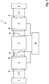
- Figure 1
- schematically shows a design of a DC/DC converter;
- Figure 2
- a more detailed view of the circuitry of the DC/DC converter according to an embodiment;
- Figures 3a to 3c
- different exemplary configurations of a converter stage as used in the DC/DC converter of
Figure 1 ; - Figures 4a to 4h
- possible configurations of resonant tanks of the DC/DC converter according to
Figure 1 ; - Figure 5
- a diagram of the operation of the state machine of the control unit; and
- Figure 6
- a timing diagram of an exemplary characteristics of the current and voltage at an output of a converter stage.
- The basic configuration of a DC/
DC converter 1 with aresonant tank 2 as an AC coupling unit is schematically shown inFigure 1 . -
Figure 1 shows afirst converter stage 3 and asecond converter stage 4 which are coupled via theAC coupling unit 2. Thefirst converter stage 3 has afirst terminal 31 to be connected to afirst DC subsystem 5. Asecond terminal 32 of thefirst converter stage 3 is coupled to theAC coupling unit 2. - The
second converter stage 4 substantially is configured similar. The second converter stage has afirst terminal 41 to be connected to asecond DC subsystem 6. Asecond terminal 42 of thefirst converter stage 3 is coupled to theAC coupling unit 2. - The first and second converter stages 3, 4 are configured to be actively operated to act as an active converter, thereby transforming a DC voltage at the respective
first terminal second terminal - In
Figure 2 , the DC/DC converter fromFigure 1 is shown in more detail in an exemplary configuration. The exemplary configuration, as shown inFigure 2 , has the first and second converter stages 3, 4 configured as H-bridges withsemiconductor devices 7, such as MOSFETs, IGBTs, GTOs, IGCTs or the like. Thesesemiconductor devices 7 include an intrinsic diode which will become effective in case the semiconductor devices of therespective converter stage - In one mode of operation, an input DC voltage udc,1 is applied onto the DC side of the
first converter stage 3 which results in an input DC current idc,1. Power transfer is from thefirst converter stage 3 to thesecond converter stage 4 which results in an output DC voltage udc,2 at the output formed by thesecond converter stage 4 with an output DC current idc,2. - Analogously, in another mode of operation, an input DC voltage udc,2 is applied onto the DC side of the
second converter stage 4 which results in an input DC current idc,2. Power transfer is from thesecond converter stage 4 to thefirst converter stage 3 which results in an output DC voltage udc,1 at the output formed by thefirst converter stage 3 with an output DC current idc,1. - DC voltage variations may be buffered by the capacities Cdc,1 and Cdc,2.
- Further embodiments of the configuration of converter stages are shown in the circuits of
Figures 3a to 3c wherein the configuration ofconverter stages Figure 3a ), a half-bridge configuration with a center tap capacitor (Figure 3b ) and a three-level voltage source converter (Figure 3c ) as known in the art. Basically, the invention is applicable for any kind of power electronics converter stage which may generate at least two voltage levels. - As shown in
Figure 2 , theAC coupling unit 2 is configured as a resonant tank. The resonant tank is shown as a combination of one or more capacitors C and one or more inductivities L1, L2, L3... and might include a medium frequency transformer 8 for a voltage level transformation. The resonant tank at least has one series capacitor C and a series inductance L1 as well as a parallel inductance L2. - Other configurations of the LLC resonant tank are shown in
Figs. 4a to 4h wherein the configurations ofFig. 4e to 4h include a transformer while the configurations ofFigs. 4a to 4d directly interconnecting the converter stages 3, 4 without any galvanic insulation. - The medium frequency transformer 8 defines the voltage ratio between the
first DC subsystem 5 and thesecond DC subsystem 6 - With reference to
Figure 2 , acontrol unit 10 is provided which is connected to the converter stages 3, 4 to operate the converter stages 3, 4 as an active inverter or as a passive rectifier selectively. When operating theconverter stage second converter terminal resonant tank 2. - Furthermore, a first
current sensor 33 may be provided at thesecond terminal 32 of thefirst converter stage 3 and a secondcurrent sensor 43 may be provided at thesecond terminal 42 of thesecond converter stage 4. Preferably, thecurrent sensors - Basically, the
control unit 10 checks the direction of the power transfer flow through theresonant tank 2 and determines the operation mode of the converter stages 3, 4 correspondingly. Thecontrol unit 10 may be operated as a state machine which determines within oneswitching period 
resonant tank 2 about the peak value of the current flow into the rectifier side. - The DC/
DC converter 1 is therefore operated in a two-mode operation wherein one of the converter stages 3, 4 is switched actively to act as an inverter applying an AC voltage its second terminal while the correspondinglyother converter stage - In conjunction with
Figure 5 , a process flow for the state machine in the control unit is described. Starting with stage S1 with a mode of operation where thefirst converter stage 3 is actively operated as an inverter, while thesecond converter stage 4 is passively operated as a rectifier. - In the current switching period, an absolute value of the peak current I2 into the
resonant tank 2 is detected on the rectifier side (second converter stage 4) by the secondcurrent sensor 43 and compared to a second predetermined peak current threshold value Ith2. The second peak current threshold value Ith2 for the peak currents are set to ensure that the offsets of thecurrent sensors current sensors - Once it is determined that the absolute value of the second peak current amplitude I2 is below the provided second peak current threshold value Ith2, a switching of the operation mode of the DC/DC converter is performed by transferring to stage S2. Accordingly, the
first converter stage 3 is switched passive, while thesecond converter stage 4 changes its mode to an active inverter. If it is determined that the absolute value of the second peak current amplitude I2 is not below the provided second peak current threshold value Ith2, the stage S1 is maintained. - In stage S2, for the next switching period, an absolute value of the peak current I1 into the
resonant tank 2 is detected on the rectifier side (first converter stage 3) by the firstcurrent sensor 33 and compared to a first predetermined peak current threshold value Ith1. - If it is determined that the absolute value of the first peak current amplitude I1 is not below the provided first peak current threshold value Ith1, the stage S2 is maintained.
- Using the current sensor which is related to the converter stage which acts as a rectifier has the advantage that only the peak current value indicating the current amplitude of the respective resonance is sufficient for the decision about the power transfer direction.
- The first and second peak current threshold value Ith1, Ith2 may be basically the same. However, if a medium frequency transformer 8 with a winding ratio different to 1 is used the peak current threshold values may be preset with the same ratio.
- In
Figure 6 , an example for the timing of one switching period is shown. While the active inverter provides a rectangular voltage signal, the resulting current flow into theresonant tank 2 almost follows a sinus characteristic due to the impedances of the resonant tank. - The operation mode as described above is particularly not sensitive to gain errors, since these only virtually change the peak current threshold value, thus increase or decrease the power range in which the alternating operation is present. Therefore, not capturing the measured current value exactly at the peak can viewed as a small gain error and thus is not critical either.
- In a preferred embodiment, the peak current amplitude I1 (ir,1 in
Figure 2 ), I2 (ir,2 inFigure 2 ) is detected once per switching period, however, the current amplitude can be detected two times per switching period related to the rising and falling edges to improve the response time of the DC/DC converter. In practical applications, the sensor offset can be corrected from drifting, since the measured current is an AC current so that a mean value of known peak values can be used to compensate the sensor drift. - Furthermore, some measurement redundancy can be achieved by removing a predicted magnetizing current value from the measured current of the active bridge. If required, the peak resonant current can also be estimated by measuring the change of the corresponding resonant capacitor voltage at the rising and falling edges. Then, the switchover current peak thresholds values may be set according to the voltage sensor noise to ensure the required operation direction is estimated correctly.
Claims (11)
- A DC/DC converter (1) for transferring an active power between two DC subsystems (5, 6) comprising:- a first converter stage (3) and a second converter stage (4) both configured to be selectively operated as an active inverter or as a passive rectifier;- an AC coupling circuit (2) for coupling the first and the second converter stage (3, 4) by means of an AC power transfer; and- a control unit (10) configured to switch the operation mode of the first and second converter stages (3, 4) depending on a measurement of an amount of power transfer through the AC coupling circuit (2).
- The DC/DC converter (1) according to claim 1, wherein the control unit (10) is configured either in a first operation mode to actively operate the first converter stage (3) and not to operate the second converter stage (4) so that it acts as a rectifier, or, in a second operation mode, to actively operate the second converter stage (4) and not to operate the first converter stage (3) so that it acts as a rectifier.
- The DC/DC converter (1) according to claim 2, wherein the control unit (10) is configured to switch from the first operation mode to the second operation mode if a power transfer flow is from the second converter stage (4) into the AC coupling circuit (2) and/or to switch from the second operation mode to the first operation mode if a power transfer flow is from the first converter stage (3) into the AC coupling circuit (2).
- The DC/DC converter (1) according to claim 2 or 3, wherein the control unit (10) is configured to switch from the first operation mode to the second operation mode if a power transfer flow from the second converter stage (4) into the AC coupling circuit (2) is below a given second threshold and/or to switch from the second operation mode to the first operation mode if a power transfer flow from the first converter stage (3) into the AC coupling circuit (2) is below a given first threshold, wherein particularly the first and the second threshold are identical.
- The DC/DC converter (1) according to claim 1, wherein the amount of power transfer is detected by a current flow through the AC coupling circuit (2).
- The DC/DC converter (1) according to claim 5, wherein a first current sensor (33) between the first converter stage (3) and the AC coupling circuit (2) is provided to measure a first absolute value of a peak current amplitude (I1) flowing into the AC coupling circuit (2) and/or wherein a second current sensor (43) between the second converter stage (4) and the AC coupling circuit (2) is provided to measure a second absolute value of a peak current amplitude (I2) flowing into the AC coupling circuit (2).
- The DC/DC converter (1) according to claim 6, wherein the control unit (10) is configured to switch from the first operation mode to the second operation mode if a second absolute value of the peak current amplitude (I2) is below a given second peak current threshold value (Ith2) and/or to switch from the second operation mode to the first operation mode if a first absolute value of the peak current amplitude (I1) is below a given first peak current threshold value (Ith1).
- The DC/DC converter (1) according to any of the claims 1 to 7, wherein the control unit (10) includes a state machine.
- The DC/DC converter (1) according to any of the claims 1 to 8, wherein the AC coupling circuit (2) includes a resonant tank, particularly an LLC resonant tank, wherein particularly the AC coupling circuit (2) includes a medium or high frequency transformer (8).
- A method for operating a DC/DC converter (1) for transferring DC power between two DC subsystems (5, 6) comprising:- a first converter stage (3) and a second converter stage (4) both configured to be operated as an active inverter or as a passive rectifier;- an AC coupling circuit (2) for coupling the first and the second converter stage (3, 4) by means of an AC power transfer;the method comprising the steps of:- switching the operation mode of the first and second converter stages (3, 4) depending on a measurement of an amount of power transfer through the AC coupling circuit.
- The method according to claim 10, wherein in a first operation mode, the first converter stage (3) is actively operated and the second converter stage (4) is not operated so that it acts as a rectifier, and , in a second operation mode, the second converter stage (4) is actively operated and the first converter stage (3) is not operated so that it acts as a rectifier, wherein it is switched from the first operation mode to the second operation mode if a power transfer flow from the second converter stage (4) into the AC coupling circuit (2) is below a given second threshold and/or it is switched from the second operation mode to the first operation mode if a power transfer flow from the first converter stage (3) into the AC coupling circuit (2) is below a given first threshold.
Priority Applications (3)
| Application Number | Priority Date | Filing Date | Title |
|---|---|---|---|
| EP20200583.1A EP3982527A1 (en) | 2020-10-07 | 2020-10-07 | A dc/dc converter and a method for operating a dc/dc converter |
| PCT/EP2021/075931 WO2022073757A1 (en) | 2020-10-07 | 2021-09-21 | A dc/dc converter and a method for operating a dc/dc converter |
| US18/029,471 US12445058B2 (en) | 2020-10-07 | 2021-09-21 | DC/DC converter and a method for operating a DC/DC converter |
Applications Claiming Priority (1)
| Application Number | Priority Date | Filing Date | Title |
|---|---|---|---|
| EP20200583.1A EP3982527A1 (en) | 2020-10-07 | 2020-10-07 | A dc/dc converter and a method for operating a dc/dc converter |
Publications (1)
| Publication Number | Publication Date |
|---|---|
| EP3982527A1 true EP3982527A1 (en) | 2022-04-13 |
Family
ID=72801400
Family Applications (1)
| Application Number | Title | Priority Date | Filing Date |
|---|---|---|---|
| EP20200583.1A Pending EP3982527A1 (en) | 2020-10-07 | 2020-10-07 | A dc/dc converter and a method for operating a dc/dc converter |
Country Status (3)
| Country | Link |
|---|---|
| US (1) | US12445058B2 (en) |
| EP (1) | EP3982527A1 (en) |
| WO (1) | WO2022073757A1 (en) |
Families Citing this family (1)
| Publication number | Priority date | Publication date | Assignee | Title |
|---|---|---|---|---|
| CN118826133B (en) * | 2024-07-09 | 2024-12-24 | 合肥工业大学 | Grid-connected inverter dual-mode fusion control method based on passivity |
Citations (3)
| Publication number | Priority date | Publication date | Assignee | Title |
|---|---|---|---|---|
| US20150015181A1 (en) * | 2012-02-14 | 2015-01-15 | Mitsubishi Electric Corporation | Dc/dc converter |
| US20170324334A1 (en) * | 2016-05-09 | 2017-11-09 | Omron Corporation | Power conversion device |
| US10587201B1 (en) * | 2019-03-12 | 2020-03-10 | Zhejiang University | Method for controlling smooth switching of operation direction of bidirectional resonant CLLC circuit |
Family Cites Families (2)
| Publication number | Priority date | Publication date | Assignee | Title |
|---|---|---|---|---|
| US12034376B2 (en) * | 2019-10-11 | 2024-07-09 | Virginia Tech Intellectual Properties, Inc. | Hybrid modulation controlled DC-to-AC converters |
| US11031897B1 (en) * | 2020-01-24 | 2021-06-08 | Rockwell Automation Technologies, Inc. | Method and apparatus for mitigation of DC bus pump-up |
-
2020
- 2020-10-07 EP EP20200583.1A patent/EP3982527A1/en active Pending
-
2021
- 2021-09-21 US US18/029,471 patent/US12445058B2/en active Active
- 2021-09-21 WO PCT/EP2021/075931 patent/WO2022073757A1/en not_active Ceased
Patent Citations (3)
| Publication number | Priority date | Publication date | Assignee | Title |
|---|---|---|---|---|
| US20150015181A1 (en) * | 2012-02-14 | 2015-01-15 | Mitsubishi Electric Corporation | Dc/dc converter |
| US20170324334A1 (en) * | 2016-05-09 | 2017-11-09 | Omron Corporation | Power conversion device |
| US10587201B1 (en) * | 2019-03-12 | 2020-03-10 | Zhejiang University | Method for controlling smooth switching of operation direction of bidirectional resonant CLLC circuit |
Non-Patent Citations (3)
| Title |
|---|
| J. HUANG ET AL.: "Implementation of bidirectional resonant DC transformer in hybrid AC/DC micro-grid", IEEE TRANSACTIONS ON SMART GRID, vol. 10, no. 2, 2019, pages 1532 - 1542, XP011710382, DOI: 10.1109/TSG.2017.2771822 |
| J. JUNG ET AL.: "Design methodology of bidirectional CLLC resonant converter for high-frequency isolation of dc distribution systems", IEEE TRANSACTIONS ON POWER ELECTRONICS, vol. 28, no. 4, 2013, pages 1741 - 1755, XP055175724, DOI: 10.1109/TPEL.2012.2213346 |
| K. TAN ET AL.: "Optimal design methodology of bidirectional LLC resonant dc/dc converter for solid state transformer application", IECON 2014 - 40TH ANNUAL CONFERENCE OF THE IEEE INDUSTRIAL ELECTRONICS SOCIETY, 2014, pages 1657 - 1664, XP032739374, DOI: 10.1109/IECON.2014.7048725 |
Also Published As
| Publication number | Publication date |
|---|---|
| WO2022073757A1 (en) | 2022-04-14 |
| US12445058B2 (en) | 2025-10-14 |
| US20230378880A1 (en) | 2023-11-23 |
Similar Documents
| Publication | Publication Date | Title |
|---|---|---|
| JP6647470B1 (en) | Power converter | |
| US5625539A (en) | Method and apparatus for controlling a DC to AC inverter system by a plurality of pulse-width modulated pulse trains | |
| CN106575923B (en) | DC-DC converter | |
| Wang et al. | Design and testing of 1 kV H-bridge power electronics building block based on 1.7 kV SiC MOSFET module | |
| CN103731036B (en) | Two-way DC/DC converters | |
| CN114514683B (en) | Current balancing in power semiconductors of DC/DC converters | |
| US10715050B2 (en) | Four-switch three phase DC-DC resonant converter | |
| CN103703663B (en) | A kind of device for reducing resonant-mode power supply | |
| US20200007022A1 (en) | Electrical Circuit with Auxiliary Voltage Source for Zero-Voltage Switching in DC-DC Converter Under All Load Conditions | |
| CN111587526A (en) | DC-DC converter device | |
| JP2003324956A (en) | Control method of series resonant bridge inverter circuit and series resonant bridge inverter circuit | |
| CN101203820A (en) | multistage active filter | |
| CN114450879B (en) | Redundancy of the resonant converter stage through frequency adaptation | |
| JPWO2019234884A1 (en) | Control device and power control system | |
| US12445058B2 (en) | DC/DC converter and a method for operating a DC/DC converter | |
| EP4451542A1 (en) | Arcp converter and control thereof | |
| US7142439B2 (en) | Zero-voltage-switching single-switched resonant DC link with minimized conduction loss | |
| CN112952791B (en) | DC power flow controller | |
| JP7132095B2 (en) | Power converter and polyphase AC power converter using the same | |
| US11888411B2 (en) | Power conversion device | |
| US10848072B2 (en) | Power supply control device, power conversion system, and power supply control method | |
| US12009674B2 (en) | Wireless power transmission with modular output | |
| US11626810B1 (en) | Multilevel power converters | |
| WO2022254711A1 (en) | Power conversion device and power supply device | |
| JP2022080081A (en) | Switching power source apparatus, and control device and control method therefor |
Legal Events
| Date | Code | Title | Description |
|---|---|---|---|
| PUAI | Public reference made under article 153(3) epc to a published international application that has entered the european phase |
Free format text: ORIGINAL CODE: 0009012 |
|
| STAA | Information on the status of an ep patent application or granted ep patent |
Free format text: STATUS: THE APPLICATION HAS BEEN PUBLISHED |
|
| AK | Designated contracting states |
Kind code of ref document: A1 Designated state(s): AL AT BE BG CH CY CZ DE DK EE ES FI FR GB GR HR HU IE IS IT LI LT LU LV MC MK MT NL NO PL PT RO RS SE SI SK SM TR |
|
| STAA | Information on the status of an ep patent application or granted ep patent |
Free format text: STATUS: REQUEST FOR EXAMINATION WAS MADE |
|
| 17P | Request for examination filed |
Effective date: 20221010 |
|
| RBV | Designated contracting states (corrected) |
Designated state(s): AL AT BE BG CH CY CZ DE DK EE ES FI FR GB GR HR HU IE IS IT LI LT LU LV MC MK MT NL NO PL PT RO RS SE SI SK SM TR |
|
| STAA | Information on the status of an ep patent application or granted ep patent |
Free format text: STATUS: EXAMINATION IS IN PROGRESS |
|
| 17Q | First examination report despatched |
Effective date: 20240403 |