EP3982074B1 - Heat exchanger - Google Patents
Heat exchanger Download PDFInfo
- Publication number
- EP3982074B1 EP3982074B1 EP20875183.4A EP20875183A EP3982074B1 EP 3982074 B1 EP3982074 B1 EP 3982074B1 EP 20875183 A EP20875183 A EP 20875183A EP 3982074 B1 EP3982074 B1 EP 3982074B1
- Authority
- EP
- European Patent Office
- Prior art keywords
- heat exchange
- collecting pipe
- tubes
- assembly
- exchange tubes
- Prior art date
- Legal status (The legal status is an assumption and is not a legal conclusion. Google has not performed a legal analysis and makes no representation as to the accuracy of the status listed.)
- Active
Links
Images



Classifications
-
- F—MECHANICAL ENGINEERING; LIGHTING; HEATING; WEAPONS; BLASTING
- F28—HEAT EXCHANGE IN GENERAL
- F28D—HEAT-EXCHANGE APPARATUS, NOT PROVIDED FOR IN ANOTHER SUBCLASS, IN WHICH THE HEAT-EXCHANGE MEDIA DO NOT COME INTO DIRECT CONTACT
- F28D1/00—Heat-exchange apparatus having stationary conduit assemblies for one heat-exchange medium only, the media being in contact with different sides of the conduit wall, in which the other heat-exchange medium is a large body of fluid, e.g. domestic or motor car radiators
- F28D1/02—Heat-exchange apparatus having stationary conduit assemblies for one heat-exchange medium only, the media being in contact with different sides of the conduit wall, in which the other heat-exchange medium is a large body of fluid, e.g. domestic or motor car radiators with heat-exchange conduits immersed in the body of fluid
- F28D1/04—Heat-exchange apparatus having stationary conduit assemblies for one heat-exchange medium only, the media being in contact with different sides of the conduit wall, in which the other heat-exchange medium is a large body of fluid, e.g. domestic or motor car radiators with heat-exchange conduits immersed in the body of fluid with tubular conduits
- F28D1/047—Heat-exchange apparatus having stationary conduit assemblies for one heat-exchange medium only, the media being in contact with different sides of the conduit wall, in which the other heat-exchange medium is a large body of fluid, e.g. domestic or motor car radiators with heat-exchange conduits immersed in the body of fluid with tubular conduits the conduits being bent, e.g. in a serpentine or zig-zag
-
- F—MECHANICAL ENGINEERING; LIGHTING; HEATING; WEAPONS; BLASTING
- F28—HEAT EXCHANGE IN GENERAL
- F28D—HEAT-EXCHANGE APPARATUS, NOT PROVIDED FOR IN ANOTHER SUBCLASS, IN WHICH THE HEAT-EXCHANGE MEDIA DO NOT COME INTO DIRECT CONTACT
- F28D1/00—Heat-exchange apparatus having stationary conduit assemblies for one heat-exchange medium only, the media being in contact with different sides of the conduit wall, in which the other heat-exchange medium is a large body of fluid, e.g. domestic or motor car radiators
- F28D1/02—Heat-exchange apparatus having stationary conduit assemblies for one heat-exchange medium only, the media being in contact with different sides of the conduit wall, in which the other heat-exchange medium is a large body of fluid, e.g. domestic or motor car radiators with heat-exchange conduits immersed in the body of fluid
- F28D1/04—Heat-exchange apparatus having stationary conduit assemblies for one heat-exchange medium only, the media being in contact with different sides of the conduit wall, in which the other heat-exchange medium is a large body of fluid, e.g. domestic or motor car radiators with heat-exchange conduits immersed in the body of fluid with tubular conduits
- F28D1/053—Heat-exchange apparatus having stationary conduit assemblies for one heat-exchange medium only, the media being in contact with different sides of the conduit wall, in which the other heat-exchange medium is a large body of fluid, e.g. domestic or motor car radiators with heat-exchange conduits immersed in the body of fluid with tubular conduits the conduits being straight
- F28D1/05316—Assemblies of conduits connected to common headers, e.g. core type radiators
- F28D1/05333—Assemblies of conduits connected to common headers, e.g. core type radiators with multiple rows of conduits or with multi-channel conduits
-
- F—MECHANICAL ENGINEERING; LIGHTING; HEATING; WEAPONS; BLASTING
- F28—HEAT EXCHANGE IN GENERAL
- F28D—HEAT-EXCHANGE APPARATUS, NOT PROVIDED FOR IN ANOTHER SUBCLASS, IN WHICH THE HEAT-EXCHANGE MEDIA DO NOT COME INTO DIRECT CONTACT
- F28D1/00—Heat-exchange apparatus having stationary conduit assemblies for one heat-exchange medium only, the media being in contact with different sides of the conduit wall, in which the other heat-exchange medium is a large body of fluid, e.g. domestic or motor car radiators
- F28D1/02—Heat-exchange apparatus having stationary conduit assemblies for one heat-exchange medium only, the media being in contact with different sides of the conduit wall, in which the other heat-exchange medium is a large body of fluid, e.g. domestic or motor car radiators with heat-exchange conduits immersed in the body of fluid
- F28D1/04—Heat-exchange apparatus having stationary conduit assemblies for one heat-exchange medium only, the media being in contact with different sides of the conduit wall, in which the other heat-exchange medium is a large body of fluid, e.g. domestic or motor car radiators with heat-exchange conduits immersed in the body of fluid with tubular conduits
- F28D1/053—Heat-exchange apparatus having stationary conduit assemblies for one heat-exchange medium only, the media being in contact with different sides of the conduit wall, in which the other heat-exchange medium is a large body of fluid, e.g. domestic or motor car radiators with heat-exchange conduits immersed in the body of fluid with tubular conduits the conduits being straight
- F28D1/05316—Assemblies of conduits connected to common headers, e.g. core type radiators
- F28D1/05341—Assemblies of conduits connected to common headers, e.g. core type radiators with multiple rows of conduits or with multi-channel conduits combined with a particular flow pattern, e.g. multi-row multi-stage radiators
-
- F—MECHANICAL ENGINEERING; LIGHTING; HEATING; WEAPONS; BLASTING
- F28—HEAT EXCHANGE IN GENERAL
- F28F—DETAILS OF HEAT-EXCHANGE AND HEAT-TRANSFER APPARATUS, OF GENERAL APPLICATION
- F28F1/00—Tubular elements; Assemblies of tubular elements
- F28F1/006—Tubular elements; Assemblies of tubular elements with variable shape, e.g. with modified tube ends, with different geometrical features
-
- F—MECHANICAL ENGINEERING; LIGHTING; HEATING; WEAPONS; BLASTING
- F28—HEAT EXCHANGE IN GENERAL
- F28F—DETAILS OF HEAT-EXCHANGE AND HEAT-TRANSFER APPARATUS, OF GENERAL APPLICATION
- F28F1/00—Tubular elements; Assemblies of tubular elements
- F28F1/02—Tubular elements of cross-section which is non-circular
- F28F1/022—Tubular elements of cross-section which is non-circular with multiple channels
-
- F—MECHANICAL ENGINEERING; LIGHTING; HEATING; WEAPONS; BLASTING
- F28—HEAT EXCHANGE IN GENERAL
- F28F—DETAILS OF HEAT-EXCHANGE AND HEAT-TRANSFER APPARATUS, OF GENERAL APPLICATION
- F28F1/00—Tubular elements; Assemblies of tubular elements
- F28F1/02—Tubular elements of cross-section which is non-circular
- F28F1/04—Tubular elements of cross-section which is non-circular polygonal, e.g. rectangular
-
- F—MECHANICAL ENGINEERING; LIGHTING; HEATING; WEAPONS; BLASTING
- F28—HEAT EXCHANGE IN GENERAL
- F28F—DETAILS OF HEAT-EXCHANGE AND HEAT-TRANSFER APPARATUS, OF GENERAL APPLICATION
- F28F1/00—Tubular elements; Assemblies of tubular elements
- F28F1/10—Tubular elements and assemblies thereof with means for increasing heat-transfer area, e.g. with fins, with projections, with recesses
- F28F1/12—Tubular elements and assemblies thereof with means for increasing heat-transfer area, e.g. with fins, with projections, with recesses the means being only outside the tubular element
- F28F1/14—Tubular elements and assemblies thereof with means for increasing heat-transfer area, e.g. with fins, with projections, with recesses the means being only outside the tubular element and extending longitudinally
- F28F1/22—Tubular elements and assemblies thereof with means for increasing heat-transfer area, e.g. with fins, with projections, with recesses the means being only outside the tubular element and extending longitudinally the means having portions engaging further tubular elements
-
- F—MECHANICAL ENGINEERING; LIGHTING; HEATING; WEAPONS; BLASTING
- F28—HEAT EXCHANGE IN GENERAL
- F28F—DETAILS OF HEAT-EXCHANGE AND HEAT-TRANSFER APPARATUS, OF GENERAL APPLICATION
- F28F9/00—Casings; Header boxes; Auxiliary supports for elements; Auxiliary members within casings
- F28F9/02—Header boxes; End plates
- F28F9/0243—Header boxes having a circular cross-section
-
- F—MECHANICAL ENGINEERING; LIGHTING; HEATING; WEAPONS; BLASTING
- F28—HEAT EXCHANGE IN GENERAL
- F28D—HEAT-EXCHANGE APPARATUS, NOT PROVIDED FOR IN ANOTHER SUBCLASS, IN WHICH THE HEAT-EXCHANGE MEDIA DO NOT COME INTO DIRECT CONTACT
- F28D1/00—Heat-exchange apparatus having stationary conduit assemblies for one heat-exchange medium only, the media being in contact with different sides of the conduit wall, in which the other heat-exchange medium is a large body of fluid, e.g. domestic or motor car radiators
- F28D1/02—Heat-exchange apparatus having stationary conduit assemblies for one heat-exchange medium only, the media being in contact with different sides of the conduit wall, in which the other heat-exchange medium is a large body of fluid, e.g. domestic or motor car radiators with heat-exchange conduits immersed in the body of fluid
- F28D1/04—Heat-exchange apparatus having stationary conduit assemblies for one heat-exchange medium only, the media being in contact with different sides of the conduit wall, in which the other heat-exchange medium is a large body of fluid, e.g. domestic or motor car radiators with heat-exchange conduits immersed in the body of fluid with tubular conduits
- F28D1/053—Heat-exchange apparatus having stationary conduit assemblies for one heat-exchange medium only, the media being in contact with different sides of the conduit wall, in which the other heat-exchange medium is a large body of fluid, e.g. domestic or motor car radiators with heat-exchange conduits immersed in the body of fluid with tubular conduits the conduits being straight
- F28D1/0535—Heat-exchange apparatus having stationary conduit assemblies for one heat-exchange medium only, the media being in contact with different sides of the conduit wall, in which the other heat-exchange medium is a large body of fluid, e.g. domestic or motor car radiators with heat-exchange conduits immersed in the body of fluid with tubular conduits the conduits being straight the conduits having a non-circular cross-section
- F28D1/05366—Assemblies of conduits connected to common headers, e.g. core type radiators
-
- F—MECHANICAL ENGINEERING; LIGHTING; HEATING; WEAPONS; BLASTING
- F28—HEAT EXCHANGE IN GENERAL
- F28F—DETAILS OF HEAT-EXCHANGE AND HEAT-TRANSFER APPARATUS, OF GENERAL APPLICATION
- F28F1/00—Tubular elements; Assemblies of tubular elements
- F28F1/02—Tubular elements of cross-section which is non-circular
- F28F1/025—Tubular elements of cross-section which is non-circular with variable shape, e.g. with modified tube ends, with different geometrical features
-
- F—MECHANICAL ENGINEERING; LIGHTING; HEATING; WEAPONS; BLASTING
- F28—HEAT EXCHANGE IN GENERAL
- F28F—DETAILS OF HEAT-EXCHANGE AND HEAT-TRANSFER APPARATUS, OF GENERAL APPLICATION
- F28F2255/00—Heat exchanger elements made of materials having special features or resulting from particular manufacturing processes
- F28F2255/16—Heat exchanger elements made of materials having special features or resulting from particular manufacturing processes extruded
Definitions
- the present disclosure relates to a field of heat exchange, and specifically to a heat exchanger according to claim 1.
- Heat exchange devices are required in automobile, household or commercial air conditioning systems.
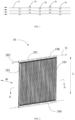
- a heat exchanger includes integrated heat exchange tubes and fin plates. As shown in FIG. 1 , the fin plates 10 and heat exchange tubes 20 of the same structure and integrated with each other are arranged in multiple rows.
- the heat exchange tubes 20 of the multiple heat exchange assemblies correspondingly form several rows, and the heat exchange tubes 20 protrude to an air-side circulation passage relative to the fin plates 10. This channel structure causes a large pressure drop in the air-side circulation passage, which makes the heat exchanger poorer in heat exchange performance, high in energy consumption and easy to frost.
- WO 2019/167840 A1 discloses a heat exchanger having the features of the preamble of claim 1 and includes a heat transfer unit formed of a heat transfer channel part which extends in a first direction, and a heat transfer auxiliary part aligned in a second direction that is inclined or orthogonal relative to the first direction.
- a first heat transfer auxiliary part is formed at an end in the second direction.
- a first length of the first heat transfer auxiliary part up to an adjacent heat transfer channel part is configured to be longer than a distance between heat transfer channel parts which are adjacent in the second direction when a plurality of heat transfer channel parts are present in the heat transfer unit.
- DE 102018203299 A1 discloses a heat exchanger with a plurality of channel bodies.
- a first flow path for a first fluid, a second flow path for a second fluid, and at least one heat exchanger structure made of heat-transferring material are provided.
- WO 2002/016834 A2 discloses a fin-less and seamless heat exchanger having a plurality of tubes which cooperatively form at least one serpentine flow path, which allows heat to be efficiently and cost effectively transferred to fluid movably contained in the tubes.
- CN 108562176 A discloses a heat exchanger including a plurality of fins that are arranged at intervals; and a plurality of heat exchange pipes extended on a surface of the fins or formed in the fins.
- the present disclosure is beneficial to improve the performance of the heat exchanger.
- the present invention provides a heat exchanger according to claim 1.
- two adjacent heat exchange tubes are arranged in a staggered manner along the array direction of the heat exchange assemblies, which is beneficial to reduce the heat exchange tubes corresponding to the two adjacent heat exchange assemblies being concentratedly arranged at a path of the air-side flow passage, to the uniformity of the flow section of the air-side flow passage, to reduce the influence of the sudden expansion and contraction of the flow channel structure on the fluid pressure drop, and to improve the heat exchange performance of the heat exchanger.
- the dimension of at least one connection area of the heat exchange assembly in the width direction of the heat exchange assembly is smaller than the dimension of the main heat exchange area in the width direction of the heat exchange assembly.
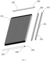
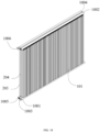
- the present disclosure provides a heat exchanger 10 which includes a group of collecting pipes and a plurality of heat exchange assemblies 101.
- the group of collecting pipes include two collecting pipes 100 respectively located at both sides in a length direction of the heat exchange assembly 101.
- Each collecting pipe 100 includes a longitudinal pipe body 201 and an inner cavity 202 located in the pipe body 201.
- the length direction of the heat exchange assembly 101 is illustrated by a solid line segment L with arrows at both sides in FIG. 2 .
- a width direction of the heat exchange assembly 101 is illustrated by a solid line segment W with arrows at both sides in FIG. 2 .
- the heat exchange assembly 101 is connected to the collecting pipes 100.
- the plurality of heat exchange assemblies 101 are arranged at intervals along a length direction D of the collecting pipes 100.
- the length direction D of the collecting pipes 100 can refer to a direction indicated by a dashed line in FIG. 2 .
- the length direction of the heat exchange assembly 101 is perpendicular to the width direction of the heat exchange assembly 101.
- the length direction D of the collecting pipes is perpendicular to the length direction of the heat exchange assembly 101 and the width direction of the heat exchange assembly 101.
- a gap between two adjacent heat exchange assemblies 101 forms an air-side flow passage.
- each heat exchange assembly 101 includes a fin plate 203 and at least one heat exchange tube 204.
- the heat exchange assemblies 101 are arranged at intervals.
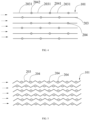
- the gap between adjacent heat exchange assemblies 101 is adapted to circulate heat exchange airflow. Referring to the direction indicated by the arrows in FIG. 4 , that is, two opposite surfaces of the two adjacent fin plates 203 both allow the heat exchange airflow to pass therethrough.
- the heat exchange assembly 101 includes a main heat exchange area 301.
- the fin plate 203 and the heat exchange tubes 204 are combined as a whole, wherein the heat exchange tubes 204 are fixedly connected to the surface of the fin plate 203, or the fin plate 203 includes a plurality of sub-plates 2031 and the heat exchange tubes 204 are connected between two adjacent sub-plates 2031.
- the heat exchange tubes 204 are connected between the two collecting pipes 100 in the length direction.
- the heat exchange tube 204 includes an inner flow channel 2041 which communicates with the inner cavities 202 of the two collecting pipes 100.
- the inner flow channel 2041 of the heat exchange tube 204 and the inner cavities 202 of the collecting pipes 100 form part of a refrigerant flow passage.
- the heat exchange assembly 101 also includes two connection areas 302 located at both sides of the main heat exchange area 301 in the length direction thereof. Refer to FIGS. 10 and 12 , an end of the connection area 302 is mainly used to be connected and fixed to the collecting pipe 100.
- the heat exchange assembly 101 may not be provided with the fin plate 203 in the connection area 302. That is, the heat exchange tube 204 may extend beyond the fin plate 203 in the length direction, and an exceeded end of the heat exchange tube 204 is connected to the collecting pipe 100. It should be understood that the end includes a small section of physical structures of the heat exchange assembly, which is located at an outer side of the heat exchange assembly along the length direction, rather than just a "point".
- the collecting pipe 100 is used for conveying the refrigerant, and the refrigerant is conveyed to the heat exchange tube 204 through the collecting pipe 100.
- the heat exchange tube 204 can exchange heat with the airflow through the tube wall 2042 and the fin plate 203.
- the fin plate 203 with a relatively large area can exchange heat with the air around the fin plate 203, thereby increasing or reducing the temperature of the air around the fin plate 203.
- the heat exchange tube 204 is connected to the fin plate 203.
- the heat exchange tube 204 is formed on the surface of the fin plate 203 or the heat exchange tube 204 is connected between two adjacent sub-plates 2031. Most portion of the heat exchange tube 204 in the length direction is in contact with the fin plate 203, so that the heat exchange area between the heat exchange tube 204 and the fin plate 203 is maximized. This also maximizes the heat exchange and heat exchange efficiency between the heat exchange tube 204 and the fin plate 203.
- At least part of the heat exchange tube 204 protrudes from at least one side of the fin plate 203 in an array direction of the heat exchange assembly 101.
- the height of the heat exchange tube 204 in the array direction of the heat exchange assembly 101 is greater than the thickness of the fin plate 203.
- the fin plate 203 may be a relatively thin strip-shaped structure, and the fin plate 203 may include two opposite surfaces.
- the height or diameter of the heat exchange tube 204 in the array direction of the heat exchange assembly 101 is greater than the thickness of the fin plate 203. Therefore, whether the heat exchange tube 204 is connected between two adjacent sub-parts 2031, or the heat exchange tube 204 is formed on the surface of the fin plate 203, the heat exchange tube 204 protrudes from at least one surface of the fin plate 203.
- the main heat exchange area corresponding to two adjacent heat exchange assemblies 101 at least one pair of adjacent heat exchange tubes 204 are arranged in a staggered manner.
- the two adjacent heat exchange tubes 204 belong to the two adjacent heat exchange assemblies 101, respectively.
- the other of the pair of the heat exchange tubes 204 is the heat exchange tube closest to the one of the pair of heat exchange tubes 204 in the heat exchange assembly 101 to which the other of the pair of heat exchange tubes 204 belongs.
- two heat exchange assemblies 101 are denoted as a heat exchange assembly A and a heat exchange assembly B, respectively.
- One heat exchange tube in the heat exchange assembly A is marked as a heat exchange tube A
- there are several heat exchange tubes in heat exchange assembly B are marked as a heat exchange tube B
- the heat exchange tube closest to the heat exchange tube A is marked as a heat exchange tube B, so that the heat exchange tube A and the heat exchange tube B are a group of heat exchange tubes which have an adjacent relationship.
- the heat exchange tube 204 of the heat exchange assembly 101 and the heat exchange tube 204 of another adjacent heat exchange assembly 101 are arranged in a staggered manner.
- the tube diameter of the heat exchange tube 204 is larger than the thickness of the fin plate 203.
- the staggered arrangement is beneficial to reduce the concentrated arrangement of the heat exchange tubes 204 in the air-side flow passage. From the perspective of the overall flow path at the air side, the position with a larger flow cross section and the position with a smaller flow cross section are homogenized, which reduces the influence of sudden expansion and contraction of the flow path structure on the fluid pressure drop.
- the present disclosure is beneficial to reduce heat exchange energy consumption, and the same flow of air can provide more heat exchange, thereby improving the heat exchange performance of the heat exchanger 10. At the same time, it helps the heat exchanger 10 to delay frosting.
- the thickness of the fin plate 203 is 0.05mm to 0.5mm
- the inner diameter of the heat exchange tube 204 is 0.4mm to 3.0mm
- the outer diameter of the heat exchange tube 204 is 0.6mm to 5mm.
- the distance between adjacent heat exchange tubes 204 is 3mm to 20mm.
- the distance between the fin plates 203 corresponding to two adjacent heat exchange assemblies 101 is 1.4mm to 6mm.
- the thickness of the fin plate 203 is 0.2mm
- the inner diameter of the heat exchange tube 204 is 1.1mm
- the outer diameter of the heat exchange tube 204 is 1.6mm
- the distance between adjacent heat exchange tubes 204 is 12mm
- the distance between the fin plates 203 corresponding to two adjacent heat exchange assemblies 101 is 1.8mm.
- the length direction of the heat exchange assembly 101 is substantially perpendicular to the length direction of the collecting pipe 100.
- the heat exchange tube 204 is welded to the surface of the fin plate 203.
- the surface of the fin plate 203 forms a concave-convex structure.
- the concave-convex structure can disturb the heat exchange airflow, thereby improving the quantity of heat exchange and heat exchange efficiency between the fin plate 203 and the heat exchange airflow.
- the heat exchange tube 204 is welded to the surface of the fin plate 203, which can also increase the heat exchange area of the air-side flow passage.
- At least one heat exchange tube 204 protrudes at the same side surface of the fin plate 203.
- the heat exchange tube 204 may be arranged on a single surface of the fin plate 203, or the fin plate 203 may include several areas, such as a first area and a second area. In the first area, the heat exchange tube 204 is provided on one surface of the fin plate 203. In the second area, the heat exchange tube 204 is arranged on an opposite surface of the fin plate 203.
- all the fin plates 203 can be divided into areas, and the heat exchange tubes 204 can be arranged on different surfaces of the fin plates 203 in different areas.
- the heat exchange tube 204 is provided on a surface corresponding to the fin plate 203.
- the heat exchange tube 204 is provided on the other surface of the corresponding fin plate 203.
- the heat exchange tubes 204 of one heat exchange assembly 101 and the heat exchange tubes 204 of the other heat exchange assembly 101 are located at different sides of the corresponding fin plate 203.
- the advantage of this arrangement is that the heat exchange tubes of the two heat exchange assemblies 101 can be simultaneously arranged in the airflow passage formed by the gap between the two heat exchange assemblies 101. Since the heat exchange tubes of the two heat exchange assemblies 101 are arranged in the staggered manner, it is helpful to form a continuous tortuous flow path in the airflow passage, increase the heat transfer coefficient of the airflow passage, and improve the heat exchange effect in the flow channel.
- the airflow passage formed by the gap between the two heat exchange assemblies 101 has a relatively uniform circulation section.
- the heat exchange tubes of the two heat exchange assemblies 101 may be simultaneously away from the airflow passage formed by the gap between the two heat exchange assemblies 101.
- Wall surfaces at both sides of the airflow passage are not provided with heat exchange tubes, and the circulation cross section is relatively uniform. Therefore, it is beneficial to improve the uniformity of the air-side flow passage, thereby improving the heat exchange performance of the heat exchanger.
- the plurality of fin plates 203 are arranged at intervals.
- a plurality of fin plates 203 are arranged in parallel at equal intervals, so that the heat exchange airflow passes uniformly, and at the same time, the wind resistance of the heat exchange airflow passing through the plurality of fin plates 203 is reduced.
- the adjacent fin plates 203 may also be arranged at unequal intervals, which is not limited in the present disclosure.
- a cross section of the fin plate 203 is a continuous polyline shape, and a cross section of the heat exchange tube 204 is a rhombus shape.
- the fin plate 203 has an angle adapted to the rhombus shape at wave crests and/or wave troughs of its polyline shape.
- the heat exchange tube 204 combines two adjacent side walls 2043 with the fin plate 203 based on its rhombus shape, so that the fin plate 203 forms a semi-enclosed arrangement for the heat exchange tube 204.
- the fin plate 203 is designed as a continuous polyline shape, and the area of the fin plate 203 in the width direction is larger, thereby increasing the heat exchange area between the fin plate 203 and the heat exchange airflow.
- An airflow vortex can be formed between the wave crests and the wave troughs of the fin plate 203, so that the heat exchange airflow stays between the fin plates 203 for a longer time, thereby improving heat exchange efficiency.
- the cross section of the fin plate 203 has a wave shape.
- the cross section of the heat exchange tube 204 is circular or elliptical.
- FIG. 6 illustrates circular heat exchange tubes 204.
- the fin plate 203 includes a plurality of straight portions 2033 and a plurality of curved portions 2032.
- the arc portion 2032 is located between two adjacent straight portions 2033.
- the arc portions 2032 form wave crests and wave troughs.
- Part of the outer surface of the heat exchange tube 204 is combined and fixed with the arc portions 2032 of the fin plate 203.
- the curvature of a connection portion of the heat exchange tube 204 and the arc portion 2032 is the same in size and direction as the curvature of the arc portion 2032.
- the heat exchange tube 204 includes a tube body 2042 located at a periphery of the inner flow channel 2041 thereof.
- the plurality of sub-plates 2031 of the fin plate 203 and the tube body 2042 are integrally formed by a die casting process or by an extrusion process.
- the tube body 2042 of the heat exchange tube 204 and the plurality of sub-plates 2032 of the fin plate 203 can be integrally formed by a pouring process or an extrusion process.
- the inner channel 2041 of the heat exchange tube 204 is formed in a processing plate, a part of the processing plate forms the tube body 2042 of the heat exchange tube 204, and parts of the processing plate located at both sides of the heat exchange tube 204 form the sub-plates 2032.
- it is realized by a first mold and a second mold which are matched with each other.
- the first mold is used to form the inner channel 2041 of the heat exchange tube 204
- the second mold has a cavity to form the rest of the heat exchange assembly 101.
- the two molds are used in combination, so that the heat exchange assembly 101 is extruded from an opening of the cavity of the second mold.
- the ratio of an area of the outer surface of the heat exchange assembly 101 to an area of the sum of the inner surfaces of all the heat exchange tubes 204 is 5 to 45.
- the area of the heat exchange tube 204 is positively correlated with its inner diameter or equivalent inner diameter.
- the inner diameter of the heat exchange tube affects the speed at which the same volume of refrigerant flows through the heat exchange tube 204.
- the ratio of an area of the outer surface of the heat exchange assembly 101 to an area of the sum of the inner surfaces of all the heat exchange tubes 204 is 5 to 45.
- the purpose of defining this range is that when the external surface area of the heat exchange assembly 101 is constant, the internal surface area of the heat exchange tube cannot be too large. That is, the tube diameter of the heat exchange tube should be as small as possible. As a result, it is trying to ensure that the refrigerant at the center of the flow section of the heat exchange tube 204 can also fully exchange heat with the tube body 2042 of the heat exchange tube 204, so as to increase the tube body of the heat exchange tube 204, thereby improving the quantity of heat exchange and heat exchange efficiency between the tube body 2042 of the heat exchange tube 204 and the refrigerant. At the same time, the wind resistance of the heat exchange tube 204 is reduced.
- the tube diameter of the heat exchange tube 204 shall be at least larger than the thickness of the fin plate 203, and the heat exchange performance of the heat exchanger 10 is improved on the premise of ensuring a small refrigerant charge. Further, the ratio of the area of the outer surface of the heat exchange assembly 101 to the area of the sum of the inner surfaces of all the heat exchange tubes 204 is 20 to 30.
- the plurality of heat exchange assemblies 101 have the same structure and shape. One heat exchange assembly 101 of the two adjacent heat exchange assemblies 101 is turned 180° relative to the other heat exchange assembly 101.
- two adjacent heat exchange assemblies 101 constitute a basic unit.
- the second heat exchange assembly 101 is turned 180° relative to the first heat exchange assembly 101 and then arranged opposite to the first heat exchange assembly 101. After that, a plurality of heat exchange assemblies 101 are arrayed with the basic unit.
- This arrangement form realizes the staggered arrangement of the heat exchange tubes 204, helps to reduce the pressure drop at the air side and also helps delay frost formation.
- the number of heat exchange tubes 204 is greater than or equal to two, and can be three, four, five, and so on.
- the plurality of heat exchange tubes 204 are arranged at intervals in the width direction of the heat exchange assembly 101.
- the fin plate 203 includes a body 400 and a plurality of bridges 401 protruding from a surface of the body 400.
- a projection of the bridge 401 on the surface of the body 400 has an elongated shape which extends along the length direction of the heat exchange assembly 101.
- a bridge hole 402 is formed between each bridge 401 and the body 400. The bridge holes 402 are adapted for the heat exchange airflow to pass therethrough.
- Shapes of the bridge holes 402 of the bridges 401 may be arch, semicircle, square, isosceles trapezoid, and the like.
- the heat exchange airflow passes through the fin plate 203, it can blow through the bridge holes 402.
- a top of the bridge 401 may abut against the fin plate 203 of another heat exchange assembly 101 or may be spaced a certain distance apart from the fin plate 203 of another heat exchange assembly 101.
- the heat exchange assembly 101 includes two connection areas 302 located at both sides of the main heat exchange area 301 in its length direction.
- the dimension of an end of at least one of the two connection areas 302 in the width direction of the heat exchange assembly 101 is smaller than the dimension of the main heat exchange area 301 in the width direction of the heat exchange assembly 101.
- the pipe body 201 of the collecting pipe 100 is provided with an insertion portion which is matched with the end of the connection area 302. At the insertion portion the pipe body 201 of the collecting pipe 100 is hermetically connected to the end of the connection area 302 of the heat exchange assembly 101.
- the inner flow channel 2041 of the heat exchange tube 204 communicates with the inner cavities 202 of the two collecting pipes 100.
- the inner flow channel 2041 of the heat exchange tube 204 and the inner cavities 202 of the collecting pipes 100 form part of the refrigerant flow passage.
- the fin plate and the heat exchange tube 204 can be necked. For example, a part of the fin plate 203 is removed, and the heat exchange tubes 204 are bent and converged.
- a length of the heat exchange tube 204 is greater than a length of the fin plate 203.
- the heat exchange tube 204 extends beyond the fin plate 203 at both sides in the length direction of the heat exchange assembly 101.
- the part of the heat exchange tube 204 located in the main heat exchange area 301 forms a main body section 501.
- the heat exchange tube 204 includes a mounting section 503 and a matching section 502.
- the end of the connection area 302 forms the mounting section 503 for mating with the collecting pipe 100.
- the mounting section 503 is located at a side of the outer surface of the collecting pipe 100 close to the inner cavity 202 thereof.
- the matching section 502 is connected between the mounting section 503 and the main body section 501.
- the heat exchange tube 204 includes the main body section 501, two mounting sections 503 and two matching sections 502.
- the two ends of the heat exchange tube 204 in the length direction respectively form two mounting sections 503.
- the two matching sections 502 are respectively located at both sides of the length of the main body section 501.
- the matching section 502 is connected between the mounting section 503 and the main body section 501.
- the plurality of heat exchange tubes 204 of the heat exchange assembly 101 include at least one first heat exchange tube 204'.
- the matching section 502 of the first heat exchange tube 204' is bent relative to the main body section 501 thereof.
- the mounting section 503 and the main body section 501 of the heat exchange tube 204 may have substantially the same extending direction.
- the mounting sections 503 of the plurality of heat exchange tubes 204 are converged in the width direction of the heat exchange assembly 101 compared to the main body section 501.
- the present disclosure provides an alternative embodiment for making this kind of heat exchange assembly.
- the length of the heat exchange tube 204 and the fin plate 203 of the preliminary processed heat exchange assembly may be the same.
- a part of the fin plate 203 can be cut off at a position near the end of the heat exchange assembly 101 while remaining the heat exchange tube 204.
- the plurality of remained heat exchange tubes 204 are bent, so that the mounting sections 503 of the plurality of heat exchange tubes 204 are converged in the width direction of the heat exchange assembly 101 compared to the main body section 501.
- the heat exchange assembly 101 can also be obtained without cutting the fin plate 203.
- an integrated processing of the heat exchange assembly 101 is performed.
- the mounting sections 503 of the plurality of heat exchange tubes 204 may be converged into one or more rows in the width direction of the heat exchange assembly 101. In the case of multiple rows, that is, the mounting sections 503 of several heat exchange tubes 204 can spread in the length direction of the heat exchange assembly 101 compared to before being converged.
- the length of the main body section 501 is greater than or equal to the length of the fin plate 203. Both the matching section 502 and the mounting section 503 extend beyond the fin plate 203 in the length direction of the heat exchange assembly 101.
- the collecting pipe 100 is a cylindrical tube of which a cross section is approximately a perfect circle.
- An outer diameter of the collecting pipe 100 is less than or equal to a distance between the main body sections 501 of the two heat exchange tubes 204 which are farthest apart in the heat exchange assembly 101.
- the pipe body 201 of the collecting pipe 100 is provided with an insertion portion. At the insertion portion, the pipe body 201 of the collecting pipe 100 and the mounting section 503 of the heat exchange tube 204 are connected in a sealed manner.
- the collecting pipe 100 and the fin plate 203 are arranged at intervals or in abutting arrangement, or the pipe body 201 of the collecting pipe 100 and the fin plate 203 are fixedly connected.
- the insertion portion includes a plurality of insertion holes 205 which extend through the pipe body 201 of the collecting pipe 100.
- the dimension of the insertion hole 205 is adapted to the end of the heat exchange tube 204.
- the plurality of insertion holes 205 are distributed at intervals on the pipe body 201 of the collecting pipe 100.
- the mounting sections 503 of the heat exchange tubes 204 are correspondingly arranged at intervals.
- the mounting sections 503 of the heat exchange tubes 204 are inserted into the collecting pipe 100 through the insertion holes 205.
- the pipe body 201 of the collecting pipe 100 and the tube body 2042 of the heat exchange tube 204 are connected in a sealed manner.
- the number of the insertion holes 205 matches the number of the heat exchange tubes 204, in a one-to-one relationship.
- the plurality of insertion holes 205 are distributed in multiple rows along the length direction of the collecting pipe 100.
- the rows of insertion holes 205 of the collecting pipe 100 are alternately staggered.
- the plurality of heat exchange tubes 204 of one heat exchange assembly 101 are arranged corresponding to at least one row of the insertion holes 205.
- the number of heat exchange tubes 204 of the heat exchange assembly 101 matches the number of at least one row of the insertion holes 205 corresponding thereto.
- axes of the mounting sections 503 of the plurality of heat exchange tubes 204 are all located on the same plane, the mounting sections 503 of the heat exchange tubes 204 are arranged in parallel, and the plurality of heat exchange tubes 204 are arranged corresponding to the row of insertion holes 205.
- the plurality of heat exchange tubes 204 include a first heat exchange tube 204' and a second heat exchange tube 204".
- the main body section 501, the matching section 502 and the mounting section 503 of the second heat exchange tube 204" are axially coincident.
- a length direction of the second heat exchange tube 204" is approximately parallel to the length direction of the heat exchange assembly 101.
- the main body section 501, the matching section 502 and the mounting section 503 of the first heat exchange tube 204' are substantially straight tubes.
- the length direction of the main body section 501 and the mounting section 503 of the first heat exchange tube 204' is substantially parallel to the length direction of the heat exchange assembly 101.
- the matching section 502 of the first heat exchange tube 204' is inclined from an end of the main body section 501 close to the collecting pipe 100, and is inclined toward the second heat exchange tube 204'.
- the number of the first heat exchange tubes 204' is greater than or equal to two.
- the number of the second heat exchange tubes 204" is greater than or equal to one.
- the first heat exchange tube 204' is closer to an edge in the width direction of the heat exchange assembly 101 than the second heat exchange tube 204".
- the plurality of first heat exchange tubes 204' are distributed at both sides of the second heat exchange tubes 204' in the width direction of the heat exchange assembly 101.
- the number of the first heat exchange tube 204' is four
- the number of the second heat exchange tube 204" is one
- the second heat exchange tube 204" has one first heat exchange tube 204' at one side and three first heat exchange tubes 204' at the other side.
- the number of first heat exchange tubes 204' is four
- the number of second heat exchange tubes 204" is two
- the two second heat exchange tubes 204" are located in the middle of the heat exchange assembly 101 in the width direction.
- the two second heat exchange tubes 204" serve as a unit.
- the four first heat exchange tubes 204' are distributed at both sides of the unit.
- the respective numbers of the first heat exchange tubes 204' at both sides may not be too limited.
- the heat exchange assembly 101 includes three heat exchange tubes 204 as an example.
- the three heat exchange tubes 204 include one second heat exchange tube 204" and two first heat exchange tubes 204' which bend the matching sections 502 of the first heat exchange tubes 204' at both sides in the width direction of the heat exchange assembly 101 toward the second heat exchange tubes 204" so as to be converged.
- the heat exchange assembly 101 is connected to the collecting pipe 100, only the heat exchange tubes 204 are inserted into the collecting pipes 100.
- a certain gap may be left between the converged heat exchange tubes 204.
- a single heat exchange tube 204 is respectively inserted into the insertion hole 205 of the collecting pipe 100.
- the mounting sections 503 of the converged heat exchange tubes 204 have no gaps or the gaps are small.
- the mounting sections 503 of the plurality of heat exchange tubes 204 are sequentially in contact with each other, and the mounting sections 503 of the plurality of heat exchange tubes 204 may be welded in sequence to form an integrated structure, which is inserted into the collecting pipe 100 as a whole.
- the insertion portion includes a plurality of mounting slots 207 which are adapted to the converged mounting sections 503 of the plurality of heat exchange tubes 204.
- the mounting sections 503 of the plurality of heat exchange tubes 204 are integrally inserted into the collecting pipe 100 through the mounting slots 207.
- the pipe body 201 of the collecting pipe 100 and the tube body 2042 of the heat exchange tube 204 are connected in a sealed manner.
- the mounting slots 207 are also distributed in multiple rows along the length of the collecting pipe 100. Two adjacent mounting slots 207 are arranged in a staggered manner. At the same time, the mounting slot 207 may have an elongated shape in a direction perpendicular to the length of the collecting pipe 100, such as a rectangle shape, an oblong shape, and the like. The shape of the mounting slot 207 can be adapted to an outer contour of the mounting section 503 of the plurality of heat exchange tubes 204 which are converged into an integrated structure.
- the mounting sections 503 of the plurality of heat exchange tubes 204 are converged in the width direction of the heat exchange assembly 101 compared to the main body section 501. In this way, when the mounting section 503 of the heat exchange tube 204 is connected and combined with the collecting pipe 100, it is beneficial to reduce the size of the collecting pipe 100 in the width direction of the heat exchange assembly 101, thereby helping to reduce the size of the collecting pipe 100 as a whole, reducing the thermal resistance effect caused by the wall thickness of the collecting pipe 100, and improving the heat exchange performance of the heat exchanger. At the same time, the relatively small welding dimension can also reduce the difficulty of welding, which further reduces the risk of leakage, and improves the stability of the heat exchanger.
- the present disclosure also provides a heat exchanger 10 which includes a plurality of collecting pipes 100 and a plurality of heat exchange assemblies 101.
- the collecting pipe 100 includes a longitudinal pipe body 201 and a collecting pipe inner cavity 202.
- the length directions of the collecting pipes 100 are substantially parallel.
- a plurality of heat exchange assemblies 101 are arranged at intervals.
- a gap between adjacent heat exchange assemblies 101 forms an air-side flow passage.
- the heat exchange assembly 101 includes a fin plate 203 and a plurality of heat exchange tubes 204.
- the heat exchange assembly 101 includes a main heat exchange area 301 in which the plurality of heat exchange tubes 204 are distributed at intervals in the width direction of the heat exchange assembly 101.
- the heat exchange tube 204 is fixedly connected to the surface of the fin plate 203, or the fin plate 203 includes a plurality of sub-plates 2031 and the heat exchange tube 204 is connected between two adjacent sub-plates 2031.
- the length of the heat exchange tube 204 is greater than the length of the fin plate 203.
- the two ends of the heat exchange tube 204 in the length direction extend beyond the fin plate 203.
- the heat exchange tubes 204 of the heat exchange assembly 101 are divided into at least two groups along the width direction of the heat exchange assembly 101.
- the number of heat exchange tubes 204 in each group is at least one.
- Each group of heat exchange tubes 204 are connected between two collecting pipes 100.
- the inner flow channels 2041 of the heat exchange tubes 204 of the two groups communicate with the inner cavities 202 of two different collecting pipes at one side.
- the inner flow channels 2041 of the heat exchange tubes 204 of the two groups communicate with the inner cavity 202 of the same collecting pipe 100 at the other side; or the inner flow channels of the heat exchange tubes 204 of the two groups respectively communicate with the inner cavities 202 of two different collecting pipes 100 at the other side, and the inner cavities 202 of the two collecting pipes 100 at the other side communicate with each other, thereby the refrigerant is capable of flowing in opposite directions in the inner flow channels 2041 of the heat exchange tubes 204 of the two groups.
- the heat exchanger 10 has at least two refrigerant flow processes formed by the plurality of heat exchange assemblies 101 and a plurality of collecting pipes 100.
- the heat exchange tubes 204 of the plurality of heat exchange assemblies 101 are alternately staggered in the length direction of the collecting pipe 100 with the heat exchange assembly 101 as a unit.
- the pipe body 201 of each collecting pipe 100 is provided with a plurality of insertion holes 205.
- the plurality of insertion holes 205 are arranged at intervals.
- the plurality of insertion holes 205 have multiple rows in the length direction of the collecting pipe 100.
- the number of insertion holes 205 in each row matches the number of heat exchange tubes 204 connected to the collecting pipe 100 in a single heat exchange assembly 101.
- Multiple rows of insertion holes 205 are alternately staggered along the length direction of the collecting pipe 100.
- the dimension of the insertion hole 205 is adapted to the dimension of the heat exchange tube 204.
- the pipe body 201 of the collecting pipe 100 and the tube body 2042 of the heat exchange tube 204 are connected in a sealed manner.
- the plurality of heat exchange tubes 204 are all straight tubes extending in the length direction of the heat exchange assembly 101.
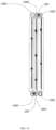
- the plurality of collecting pipes 100 include a first collecting pipe 1001, a second collecting pipe 1002, a third collecting pipe 1003 and a fourth collecting pipe 1004.
- the first collecting pipe 1001 and the third collecting pipe 1003 are arranged side by side.
- the second collecting pipe 1002 and the fourth collecting pipe 1004 are arranged side by side.
- the first collecting pipe 1001 and the second collecting pipe 1002 are oppositely arranged in the length direction of the heat exchange assembly 101.
- the third collecting pipe 1003 and the fourth collecting pipe 1004 are arranged oppositely in the length direction of the heat exchange assembly 101.
- the heat exchanger 10 has two refrigerant flow processes in the width direction of the heat exchange assembly 101, and each refrigerant flow process includes at least one heat exchange tube 204 of each heat exchange assembly 101.
- Two of the plurality of collecting pipes 100 form a group, and each refrigerant flow process includes a group of collecting pipes 100.
- the two collecting pipes 100 of the group are respectively located at both sides along the length direction of the heat exchange tube 204 corresponding to the refrigerant flow process to which they belong.
- the second collecting pipe 1002 and the fourth collecting pipe 1004 abut against each other.
- the tube bodies 201 of the second collecting pipe 1002 and the fourth collecting pipe 1004 are both provided with a first communication hole 208.
- the first communication hole 208 of the second collecting pipe 1002 is aligned with the first communication hole 208 of the fourth collecting pipe 1004, so that the inner cavity 202 of the second collecting pipe 1002 and the inner cavity of the fourth collecting pipe 1004 are communicated with each other through a mated first communication hole 208 at a position where the two pipe bodies 201 are abutted with each other.
- the heat exchanger 10 includes a first connection body 209 which is at least partially located between the second collecting pipe 1002 and the fourth collecting pipe 1004.
- the shape of the first connection body 209 is roughly a triangular prism of which two of its three side surfaces are recessed to form arc-shaped concave surfaces.
- the shapes of the two arc-shaped concave surfaces respectively correspond to the shapes of partial surfaces of the second collecting pipe 1002 and the fourth collecting pipe 1004.
- Part of the surfaces of the second collecting pipe 1002 and the fourth collecting pipe 1004 is welded to at least part of the arc-shaped concave surfaces.
- the welding method may be brazing.
- the first connection body 209 is provided with a second communication hole 210 extending through the two concave surfaces.
- the pipe body 201 of the second collecting pipe 1002 and the pipe body 201 of the fourth collecting pipe 1004 are both provided with a third communication hole 211.
- Two sides of the second communication hole 210 are aligned with the third communication hole 211 of the second collecting pipe 1002 and the third communication hole 211 of the fourth collecting pipe 1004, respectively.
- the pipe body 201 of the second collecting pipe 1002 is separated from the pipe body 201 of the fourth collecting pipe 1004 at a position where the third communication hole 211 is opened.
- the third communication hole 211 of the second collecting pipe 1002 is communicated with the third communication hole 211 of the fourth collecting pipe 1004 through the second communication hole 210, so that the inner cavity 202 of the second collecting pipe 1002 is communicated with the inner cavity 202 of the fourth collecting pipe 1004.
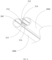
- the heat exchanger 10 includes a second connection body 212 which is provided with a fourth communication hole 213.
- the second collecting pipe 1002 and the fourth collecting pipe 1004 are provided with a fifth communication hole 214 corresponding to the fourth communication hole 213.
- the second connection body 212 is welded between the second collecting pipe 1002 and the fourth collecting pipe 1004.
- the second connection body 212 may have a long plate shape.
- a side surface of the second connection body 212 facing the second collecting pipe 1002 is an arc-shaped inner concave surface which matches with the pipe body of the second collecting pipe 1002.
- a side surface of the second connection body 212 facing the second collecting pipe 1002 is an arc-shaped inner concave surface which matches with the pipe body of the fourth collecting pipe 1004.
- Two sides of the fourth communication hole 213 are aligned with the fifth communication hole 214 of the second collecting pipe 1002 and the fifth communication hole 214 of the fourth collecting pipe 1004, respectively.
- the inner cavity 202 of the second collecting pipe 1002 and the inner cavity 202 of the fourth collecting pipe 1004 are communicated with each other through the respective fifth communication hole 214 and the fourth communication hole 213.
- the present disclosure also provides a heat exchanger 10 without the first connection body 209 or the second connection body 212.
- the plurality of collecting pipes 100 include a first collecting pipe 1001, a second collecting pipe 1002 and a third collecting pipe 1003.
- the first collecting pipe 1001 and the third collecting pipe 1003 are arranged side by side.
- the first collecting pipe 1001 and the third collecting pipe 1003 are located at one side in the length direction of the heat exchange assembly 101, and the second collecting pipe 1002 is located at the other side in the length direction of the heat exchange assembly 101.
- a plurality of groups of heat exchange tubes 204 include a first group of heat exchange tubes S1 and a second group of heat exchange tubes S2 which are adjacent to the first group of heat exchange tubes S1 in the width direction of the heat exchange assembly 101.
- the first group of heat exchange tubes S1 are connected between the first collecting pipe 1001 and the second collecting pipe 1002.
- the second group of heat exchange tubes S2 are connected between the third collecting pipe 1003 and the second collecting pipe 1002.
- the number of heat exchange tubes S1 in the first group and the number of heat exchange tubes S2 in the second group are both greater than or equal to one.
- the number of heat exchange tubes S1 in the first group and the number of heat exchange tubes S2 in the second group may be the same or different. In the embodiment provided in the present disclosure, the number of the first group of heat exchange tubes S1 is two, and the number of the second group of heat exchange tube S2 is one.
- Each heat exchange tube 204 of the first group of heat exchange tubes S1 has a first end 11 connected to the first collecting pipe 1001 and a second end 12 connected to the second collecting pipe 1002.
- Each heat exchange tube 204 of the second group of heat exchange tubes S2 has a third end 13 connected to the third collecting pipe 1003 and a fourth end 14 connected to the second collecting pipe 1002. The second end 12 and the fourth end 14 are converged in the width direction of the heat exchange assembly 101 compared to the first end 11 and the third end 13.
- the second end portion 12 and the fourth end portion 14 which are converged together can be inserted into the second collecting pipe 1002 as a whole, or welded into an integral structure and then inserted into the second collecting pipe 1002 as a whole. Of course, they can also be inserted into the second collecting pipe 1002 separately, which is not too limited in the present disclosure.
- refrigerant flow passage may also include more flow channel processes, such as four processes, five processes, etc., which are not too limited in the present disclosure.
- Three or more refrigerant flow processes are superimposed on the basis of two refrigerant flow processes.
- FIG. 19 for example, in the case of three processes, compared with the two processes in which a fifth collecting pipe 1005 and a sixth collecting pipe 1006 are added, the first collecting pipe 1001, the third collecting pipe 1003 and the fifth collecting pipe 1005 are arranged side by side, the second collecting pipe 1002, the fourth collecting pipe 1004 and the sixth collecting pipe 1006 are arranged side by side, and the inner cavity 202 of the third collecting pipe 1003 is in communication with the inner cavity 202 of the fifth collecting pipe 1005.
- the three refrigerant flow processes have flow directions similar to a serpentine twist.
- first connection body 209 or a second connection body 212 may also be provided between the third collecting pipe 1003 and the fifth collecting pipe 1005.
- the function of the first connection body 209 or the second connection body 212 has been described in detail above, which will not be repeated here.
- the plurality of collecting pipes 100 may all be cylindrical tubes with a perfect circular cross section, and tube diameters of the plurality of collecting pipes 100 are all the same.
- a cross section of the fin plate 203 is a continuous polyline shape or a wave shape.
- the cross-sectional shape of the heat exchange tube 204 is adapted to the wave crests or the wave troughs of the polyline shape or the wave shape.
- Part of the outer surface of the heat exchange tube 204 is welded and fixed to the wave crests or the wave troughs of the polyline shape or the wave shape, so that the fin plate 203 partially surrounds the heat exchange tube 204 at the wave crests or the wave troughs of the polyline shape or the wave shape.
Landscapes
- Engineering & Computer Science (AREA)
- Physics & Mathematics (AREA)
- Thermal Sciences (AREA)
- Mechanical Engineering (AREA)
- General Engineering & Computer Science (AREA)
- Geometry (AREA)
- Heat-Exchange Devices With Radiators And Conduit Assemblies (AREA)
Description
- The present disclosure relates to a field of heat exchange, and specifically to a heat exchanger according to
claim 1. - Heat exchange devices are required in automobile, household or commercial air conditioning systems. One solution in the related art is that a heat exchanger includes integrated heat exchange tubes and fin plates. As shown in
FIG. 1 , thefin plates 10 andheat exchange tubes 20 of the same structure and integrated with each other are arranged in multiple rows. In the related art, after the heat exchange assemblies composed of multiple integratedheat exchange tubes 20 and thefin plates 10 are arranged, theheat exchange tubes 20 of the multiple heat exchange assemblies correspondingly form several rows, and theheat exchange tubes 20 protrude to an air-side circulation passage relative to thefin plates 10. This channel structure causes a large pressure drop in the air-side circulation passage, which makes the heat exchanger poorer in heat exchange performance, high in energy consumption and easy to frost. -
WO 2019/167840 A1 discloses a heat exchanger having the features of the preamble ofclaim 1 and includes a heat transfer unit formed of a heat transfer channel part which extends in a first direction, and a heat transfer auxiliary part aligned in a second direction that is inclined or orthogonal relative to the first direction. In the heat transfer unit, a first heat transfer auxiliary part is formed at an end in the second direction. A first length of the first heat transfer auxiliary part up to an adjacent heat transfer channel part is configured to be longer than a distance between heat transfer channel parts which are adjacent in the second direction when a plurality of heat transfer channel parts are present in the heat transfer unit. -
DE 102018203299 A1 discloses a heat exchanger with a plurality of channel bodies. A first flow path for a first fluid, a second flow path for a second fluid, and at least one heat exchanger structure made of heat-transferring material are provided. -
WO 2002/016834 A2 discloses a fin-less and seamless heat exchanger having a plurality of tubes which cooperatively form at least one serpentine flow path, which allows heat to be efficiently and cost effectively transferred to fluid movably contained in the tubes. -
CN 108562176 A discloses a heat exchanger including a plurality of fins that are arranged at intervals; and a plurality of heat exchange pipes extended on a surface of the fins or formed in the fins. - The present disclosure is beneficial to improve the performance of the heat exchanger.
- The present invention provides a heat exchanger according to
claim 1. - In the present disclosure, two adjacent heat exchange tubes are arranged in a staggered manner along the array direction of the heat exchange assemblies, which is beneficial to reduce the heat exchange tubes corresponding to the two adjacent heat exchange assemblies being concentratedly arranged at a path of the air-side flow passage, to the uniformity of the flow section of the air-side flow passage, to reduce the influence of the sudden expansion and contraction of the flow channel structure on the fluid pressure drop, and to improve the heat exchange performance of the heat exchanger.
- In the heat exchanger of the present disclosure, the dimension of at least one connection area of the heat exchange assembly in the width direction of the heat exchange assembly is smaller than the dimension of the main heat exchange area in the width direction of the heat exchange assembly. In this way, when the end of the heat exchange assembly is connected and combined with the collecting pipe, it is beneficial to reduce the size of the collecting pipe in the width direction of the heat exchange assembly, reduce the thermal resistance effect caused by the wall thickness of the collecting pipe, and improve the heat exchange performance of the heat exchanger.
-
-
FIG. 1 is a schematic view of an integrated structure of fins and heat exchange tubes in related art; -
FIG. 2 is a schematic perspective view of a heat exchanger in accordance with an embodiment of the present disclosure; -
FIG. 3 is a schematic view of an exploded structure of the heat exchanger provided inFIG.2 of the present disclosure; -
FIG. 4 is a schematic structural view of the heat exchange assembly provided by a specific embodiment of the present disclosure; -
FIG. 5 is a schematic structural view of the heat exchange assembly provided by another specific embodiment of the present disclosure; -
FIG. 6 is a schematic structural view of the heat exchange assembly provided by another specific embodiment of the present disclosure; -
FIG. 7 is an enlarged schematic view of a partial structure of the heat exchange assembly provided by an embodiment of the present disclosure; -
FIG. 8 is a schematic perspective view of a structure of the heat exchanger provided by another embodiment of the present disclosure; -
FIG. 9 is a schematic side view of a heat exchanger not falling into the scope of the claims; -
FIG. 10 is an enlarged schematic view of the partial structure of the heat exchange assembly ofFig. 9 ; -
FIG. 11 is an enlarged schematic view of the partial structure of a collecting pipe ofFig. 9 ; -
FIG. 12 is an enlarged schematic view of the partial structure of the heat exchange assembly provided by an embodiment of the present disclosure; -
FIG. 13 is an enlarged schematic view of the partial structure of the collecting pipe corresponding to the embodiment ofFig. 12 ; -
FIG. 14 is a schematic structural view of the multi-process heat exchanger provided by an embodiment of the present disclosure; -
FIG. 15 is a schematic structural view of the connection between the second collecting pipe and the fourth collecting pipe of a heat exchanger not falling into the scope of the claims; -
FIG. 16 is a schematic structural view of the connection between the second collecting pipe and the fourth collecting pipe of a heat exchanger not falling into the scope of the claims; -
FIG. 17 is a schematic structural view of the multi-process heat exchanger provided by another embodiment of the present disclosure; -
FIG. 18 is a schematic structural view of the multi-process heat exchanger provided by another embodiment of the present disclosure; and -
FIG. 19 is another structural schematic view of the multi-process heat exchanger provided inFIG. 18 of the present disclosure. - Technical solutions in the embodiments of the present disclosure will be clearly and completely described below in conjunction with the figures in the embodiments of the present disclosure. Obviously, the described embodiments are only a part of the embodiments of the present disclosure, rather than all the embodiments. Based on the embodiments in the present disclosure, all other embodiments obtained by a person of ordinary skill in the art without creative work shall fall within the protection scope of the present disclosure. There are several specific embodiments in the present disclosure, and the features in these embodiments can be combined with each other if there is no conflict. When the description refers to the figures, unless otherwise specified, the same numbers in different figures indicate the same or similar elements.
- Please refer to
FIGS. 2 and3 , the present disclosure provides aheat exchanger 10 which includes a group of collecting pipes and a plurality ofheat exchange assemblies 101. In an embodiment of the present disclosure, the group of collecting pipes include twocollecting pipes 100 respectively located at both sides in a length direction of theheat exchange assembly 101. Eachcollecting pipe 100 includes alongitudinal pipe body 201 and aninner cavity 202 located in thepipe body 201. The length direction of theheat exchange assembly 101 is illustrated by a solid line segment L with arrows at both sides inFIG. 2 . A width direction of theheat exchange assembly 101 is illustrated by a solid line segment W with arrows at both sides inFIG. 2 . - The
heat exchange assembly 101 is connected to thecollecting pipes 100. The plurality ofheat exchange assemblies 101 are arranged at intervals along a length direction D of thecollecting pipes 100. The length direction D of thecollecting pipes 100 can refer to a direction indicated by a dashed line inFIG. 2 . Referring toFIG. 2 , in an embodiment of the present disclosure, the length direction of theheat exchange assembly 101 is perpendicular to the width direction of theheat exchange assembly 101. The length direction D of the collecting pipes is perpendicular to the length direction of theheat exchange assembly 101 and the width direction of theheat exchange assembly 101. A gap between two adjacent heat exchange assemblies 101 forms an air-side flow passage. - Among the plurality of
heat exchange assemblies 101, eachheat exchange assembly 101 includes afin plate 203 and at least oneheat exchange tube 204. Theheat exchange assemblies 101 are arranged at intervals. The gap between adjacentheat exchange assemblies 101 is adapted to circulate heat exchange airflow. Referring to the direction indicated by the arrows inFIG. 4 , that is, two opposite surfaces of the twoadjacent fin plates 203 both allow the heat exchange airflow to pass therethrough. - The
heat exchange assembly 101 includes a mainheat exchange area 301. In the mainheat exchange area 301, thefin plate 203 and theheat exchange tubes 204 are combined as a whole, wherein theheat exchange tubes 204 are fixedly connected to the surface of thefin plate 203, or thefin plate 203 includes a plurality ofsub-plates 2031 and theheat exchange tubes 204 are connected between twoadjacent sub-plates 2031. Theheat exchange tubes 204 are connected between the twocollecting pipes 100 in the length direction. Theheat exchange tube 204 includes aninner flow channel 2041 which communicates with theinner cavities 202 of the two collectingpipes 100. Theinner flow channel 2041 of theheat exchange tube 204 and theinner cavities 202 of the collectingpipes 100 form part of a refrigerant flow passage. - The
heat exchange assembly 101 also includes twoconnection areas 302 located at both sides of the mainheat exchange area 301 in the length direction thereof. Refer toFIGS. 10 and12 , an end of theconnection area 302 is mainly used to be connected and fixed to the collectingpipe 100. Theheat exchange assembly 101 may not be provided with thefin plate 203 in theconnection area 302. That is, theheat exchange tube 204 may extend beyond thefin plate 203 in the length direction, and an exceeded end of theheat exchange tube 204 is connected to the collectingpipe 100. It should be understood that the end includes a small section of physical structures of the heat exchange assembly, which is located at an outer side of the heat exchange assembly along the length direction, rather than just a "point". - The collecting
pipe 100 is used for conveying the refrigerant, and the refrigerant is conveyed to theheat exchange tube 204 through the collectingpipe 100. Theheat exchange tube 204 can exchange heat with the airflow through thetube wall 2042 and thefin plate 203. Thefin plate 203 with a relatively large area can exchange heat with the air around thefin plate 203, thereby increasing or reducing the temperature of the air around thefin plate 203. - The
heat exchange tube 204 is connected to thefin plate 203. Theheat exchange tube 204 is formed on the surface of thefin plate 203 or theheat exchange tube 204 is connected between two adjacent sub-plates 2031. Most portion of theheat exchange tube 204 in the length direction is in contact with thefin plate 203, so that the heat exchange area between theheat exchange tube 204 and thefin plate 203 is maximized. This also maximizes the heat exchange and heat exchange efficiency between theheat exchange tube 204 and thefin plate 203. - At least part of the
heat exchange tube 204 protrudes from at least one side of thefin plate 203 in an array direction of theheat exchange assembly 101. In an embodiment provided in the present disclosure, the height of theheat exchange tube 204 in the array direction of theheat exchange assembly 101 is greater than the thickness of thefin plate 203. Optionally, thefin plate 203 may be a relatively thin strip-shaped structure, and thefin plate 203 may include two opposite surfaces. The height or diameter of theheat exchange tube 204 in the array direction of theheat exchange assembly 101 is greater than the thickness of thefin plate 203. Therefore, whether theheat exchange tube 204 is connected between twoadjacent sub-parts 2031, or theheat exchange tube 204 is formed on the surface of thefin plate 203, theheat exchange tube 204 protrudes from at least one surface of thefin plate 203. - Referring to the projections of the main heat exchange areas of the plurality of
heat exchange assemblies 101 on a plane perpendicular to the length direction of theheat exchange assemblies 101 as shown inFIG. 4 , in the main heat exchange area corresponding to two adjacentheat exchange assemblies 101, at least one pair of adjacentheat exchange tubes 204 are arranged in a staggered manner. The two adjacentheat exchange tubes 204 belong to the two adjacentheat exchange assemblies 101, respectively. Regard to one of the pair ofheat exchange tubes 204, the other of the pair of theheat exchange tubes 204 is the heat exchange tube closest to the one of the pair ofheat exchange tubes 204 in theheat exchange assembly 101 to which the other of the pair ofheat exchange tubes 204 belongs. For example, twoheat exchange assemblies 101 are denoted as a heat exchange assembly A and a heat exchange assembly B, respectively. One heat exchange tube in the heat exchange assembly A is marked as a heat exchange tube A, and there are several heat exchange tubes in heat exchange assembly B. Among them, the heat exchange tube closest to the heat exchange tube A is marked as a heat exchange tube B, so that the heat exchange tube A and the heat exchange tube B are a group of heat exchange tubes which have an adjacent relationship. - As shown in
FIG. 4 , theheat exchange tube 204 of theheat exchange assembly 101 and theheat exchange tube 204 of another adjacentheat exchange assembly 101 are arranged in a staggered manner. Generally, the tube diameter of theheat exchange tube 204 is larger than the thickness of thefin plate 203. Corresponding to the main heat exchange area of the adjacentheat exchange assembly 101, the staggered arrangement is beneficial to reduce the concentrated arrangement of theheat exchange tubes 204 in the air-side flow passage. From the perspective of the overall flow path at the air side, the position with a larger flow cross section and the position with a smaller flow cross section are homogenized, which reduces the influence of sudden expansion and contraction of the flow path structure on the fluid pressure drop. The present disclosure is beneficial to reduce heat exchange energy consumption, and the same flow of air can provide more heat exchange, thereby improving the heat exchange performance of theheat exchanger 10. At the same time, it helps theheat exchanger 10 to delay frosting. - In an embodiment provided by the present disclosure, the thickness of the
fin plate 203 is 0.05mm to 0.5mm, the inner diameter of theheat exchange tube 204 is 0.4mm to 3.0mm, and the outer diameter of theheat exchange tube 204 is 0.6mm to 5mm. In a singleheat exchange assembly 101, the distance between adjacentheat exchange tubes 204 is 3mm to 20mm. The distance between thefin plates 203 corresponding to two adjacentheat exchange assemblies 101 is 1.4mm to 6mm. - Further, in an alternative embodiment of the present disclosure, the thickness of the
fin plate 203 is 0.2mm, the inner diameter of theheat exchange tube 204 is 1.1mm, the outer diameter of theheat exchange tube 204 is 1.6mm, the distance between adjacentheat exchange tubes 204 is 12mm, and the distance between thefin plates 203 corresponding to two adjacentheat exchange assemblies 101 is 1.8mm. - As shown in
FIG. 2 , the length direction of theheat exchange assembly 101 is substantially perpendicular to the length direction of the collectingpipe 100. - In an embodiment provided by the present disclosure, referring to
FIGS. 5 and6 , in the mainheat exchange area 301, theheat exchange tube 204 is welded to the surface of thefin plate 203. By protruding theheat exchange tube 204 beyond the surface of thefin plate 203, the surface of thefin plate 203 forms a concave-convex structure. When the heat exchange airflow flows through the surface of thefin plate 203, the concave-convex structure can disturb the heat exchange airflow, thereby improving the quantity of heat exchange and heat exchange efficiency between thefin plate 203 and the heat exchange airflow. At the same time, theheat exchange tube 204 is welded to the surface of thefin plate 203, which can also increase the heat exchange area of the air-side flow passage. - In a same
heat exchange assembly 101, at least oneheat exchange tube 204 protrudes at the same side surface of thefin plate 203. Of course, there can be many ways to arrange theheat exchange tube 204 on thefin plate 203. Theheat exchange tube 204 may be arranged on a single surface of thefin plate 203, or thefin plate 203 may include several areas, such as a first area and a second area. In the first area, theheat exchange tube 204 is provided on one surface of thefin plate 203. In the second area, theheat exchange tube 204 is arranged on an opposite surface of thefin plate 203. Of course, all thefin plates 203 can be divided into areas, and theheat exchange tubes 204 can be arranged on different surfaces of thefin plates 203 in different areas. For example, regard to the first mpieces fin plates 203, theheat exchange tube 204 is provided on a surface corresponding to thefin plate 203. Regard to the last npieces fin plates 203, theheat exchange tube 204 is provided on the other surface of the correspondingfin plate 203. - Optionally, among the two adjacent
heat exchange assemblies 101, theheat exchange tubes 204 of oneheat exchange assembly 101 and theheat exchange tubes 204 of the otherheat exchange assembly 101 are located at different sides of the correspondingfin plate 203. The advantage of this arrangement is that the heat exchange tubes of the twoheat exchange assemblies 101 can be simultaneously arranged in the airflow passage formed by the gap between the twoheat exchange assemblies 101. Since the heat exchange tubes of the twoheat exchange assemblies 101 are arranged in the staggered manner, it is helpful to form a continuous tortuous flow path in the airflow passage, increase the heat transfer coefficient of the airflow passage, and improve the heat exchange effect in the flow channel. The airflow passage formed by the gap between the twoheat exchange assemblies 101 has a relatively uniform circulation section. Alternatively, the heat exchange tubes of the twoheat exchange assemblies 101 may be simultaneously away from the airflow passage formed by the gap between the twoheat exchange assemblies 101. Wall surfaces at both sides of the airflow passage are not provided with heat exchange tubes, and the circulation cross section is relatively uniform. Therefore, it is beneficial to improve the uniformity of the air-side flow passage, thereby improving the heat exchange performance of the heat exchanger. - The plurality of
fin plates 203 are arranged at intervals. Optionally, a plurality offin plates 203 are arranged in parallel at equal intervals, so that the heat exchange airflow passes uniformly, and at the same time, the wind resistance of the heat exchange airflow passing through the plurality offin plates 203 is reduced. Or, theadjacent fin plates 203 may also be arranged at unequal intervals, which is not limited in the present disclosure. - As shown in
FIG. 5 , on a plane perpendicular to the length direction of theheat exchange assembly 101, a cross section of thefin plate 203 is a continuous polyline shape, and a cross section of theheat exchange tube 204 is a rhombus shape. Thefin plate 203 has an angle adapted to the rhombus shape at wave crests and/or wave troughs of its polyline shape. Theheat exchange tube 204 combines two adjacent side walls 2043 with thefin plate 203 based on its rhombus shape, so that thefin plate 203 forms a semi-enclosed arrangement for theheat exchange tube 204. - The
fin plate 203 is designed as a continuous polyline shape, and the area of thefin plate 203 in the width direction is larger, thereby increasing the heat exchange area between thefin plate 203 and the heat exchange airflow. An airflow vortex can be formed between the wave crests and the wave troughs of thefin plate 203, so that the heat exchange airflow stays between thefin plates 203 for a longer time, thereby improving heat exchange efficiency. - Except for the polyline cross section, as shown in
FIG. 6 , on a plane perpendicular to the length direction of theheat exchange assembly 101, the cross section of thefin plate 203 has a wave shape. The cross section of theheat exchange tube 204 is circular or elliptical.FIG. 6 illustrates circularheat exchange tubes 204. - The
fin plate 203 includes a plurality ofstraight portions 2033 and a plurality ofcurved portions 2032. Thearc portion 2032 is located between two adjacentstraight portions 2033. Thearc portions 2032 form wave crests and wave troughs. Part of the outer surface of theheat exchange tube 204 is combined and fixed with thearc portions 2032 of thefin plate 203. The curvature of a connection portion of theheat exchange tube 204 and thearc portion 2032 is the same in size and direction as the curvature of thearc portion 2032. - Referring to
FIG. 4 , theheat exchange tube 204 includes atube body 2042 located at a periphery of theinner flow channel 2041 thereof. The plurality ofsub-plates 2031 of thefin plate 203 and thetube body 2042 are integrally formed by a die casting process or by an extrusion process. - The
tube body 2042 of theheat exchange tube 204 and the plurality ofsub-plates 2032 of thefin plate 203 can be integrally formed by a pouring process or an extrusion process. Equivalently, theinner channel 2041 of theheat exchange tube 204 is formed in a processing plate, a part of the processing plate forms thetube body 2042 of theheat exchange tube 204, and parts of the processing plate located at both sides of theheat exchange tube 204 form the sub-plates 2032. In an optional extrusion process, it is realized by a first mold and a second mold which are matched with each other. The first mold is used to form theinner channel 2041 of theheat exchange tube 204, and the second mold has a cavity to form the rest of theheat exchange assembly 101. The two molds are used in combination, so that theheat exchange assembly 101 is extruded from an opening of the cavity of the second mold. - In a single
heat exchange assembly 101, the ratio of an area of the outer surface of theheat exchange assembly 101 to an area of the sum of the inner surfaces of all theheat exchange tubes 204 is 5 to 45. When the flow cross section of theheat exchange tube 204 may be round, square, rectangular, polygonal isosceles trapezoid or special shape, the area of theheat exchange tube 204 is positively correlated with its inner diameter or equivalent inner diameter. The inner diameter of the heat exchange tube affects the speed at which the same volume of refrigerant flows through theheat exchange tube 204. The ratio of an area of the outer surface of theheat exchange assembly 101 to an area of the sum of the inner surfaces of all theheat exchange tubes 204 is 5 to 45. The purpose of defining this range is that when the external surface area of theheat exchange assembly 101 is constant, the internal surface area of the heat exchange tube cannot be too large. That is, the tube diameter of the heat exchange tube should be as small as possible. As a result, it is trying to ensure that the refrigerant at the center of the flow section of theheat exchange tube 204 can also fully exchange heat with thetube body 2042 of theheat exchange tube 204, so as to increase the tube body of theheat exchange tube 204, thereby improving the quantity of heat exchange and heat exchange efficiency between thetube body 2042 of theheat exchange tube 204 and the refrigerant. At the same time, the wind resistance of theheat exchange tube 204 is reduced. Of course, it is also necessary to ensure that the inner surface area of theheat exchange tube 204 cannot be too small. The tube diameter of theheat exchange tube 204 shall be at least larger than the thickness of thefin plate 203, and the heat exchange performance of theheat exchanger 10 is improved on the premise of ensuring a small refrigerant charge. Further, the ratio of the area of the outer surface of theheat exchange assembly 101 to the area of the sum of the inner surfaces of all theheat exchange tubes 204 is 20 to 30. - The plurality of
heat exchange assemblies 101 have the same structure and shape. Oneheat exchange assembly 101 of the two adjacentheat exchange assemblies 101 is turned 180° relative to the otherheat exchange assembly 101. - In an embodiment provided by the present disclosure, two adjacent
heat exchange assemblies 101 constitute a basic unit. In the basic unit, the secondheat exchange assembly 101 is turned 180° relative to the firstheat exchange assembly 101 and then arranged opposite to the firstheat exchange assembly 101. After that, a plurality ofheat exchange assemblies 101 are arrayed with the basic unit. This arrangement form realizes the staggered arrangement of theheat exchange tubes 204, helps to reduce the pressure drop at the air side and also helps delay frost formation. - In a single
heat exchange assembly 101, the number ofheat exchange tubes 204 is greater than or equal to two, and can be three, four, five, and so on. The plurality ofheat exchange tubes 204 are arranged at intervals in the width direction of theheat exchange assembly 101. - As shown in
FIG. 7 , thefin plate 203 includes abody 400 and a plurality ofbridges 401 protruding from a surface of thebody 400. A projection of thebridge 401 on the surface of thebody 400 has an elongated shape which extends along the length direction of theheat exchange assembly 101. Abridge hole 402 is formed between eachbridge 401 and thebody 400. The bridge holes 402 are adapted for the heat exchange airflow to pass therethrough. - Shapes of the bridge holes 402 of the
bridges 401 may be arch, semicircle, square, isosceles trapezoid, and the like. When the heat exchange airflow passes through thefin plate 203, it can blow through the bridge holes 402. A top of thebridge 401 may abut against thefin plate 203 of anotherheat exchange assembly 101 or may be spaced a certain distance apart from thefin plate 203 of anotherheat exchange assembly 101. By providing thebridges 401, the heat exchange can be enhanced, and the heat exchange efficiency between thefin plate 203 and the air can be improved. - Referring to
FIGS. 8 ,9 ,10 and12 , theheat exchange assembly 101 includes twoconnection areas 302 located at both sides of the mainheat exchange area 301 in its length direction. The dimension of an end of at least one of the twoconnection areas 302 in the width direction of theheat exchange assembly 101 is smaller than the dimension of the mainheat exchange area 301 in the width direction of theheat exchange assembly 101. Thepipe body 201 of the collectingpipe 100 is provided with an insertion portion which is matched with the end of theconnection area 302. At the insertion portion thepipe body 201 of the collectingpipe 100 is hermetically connected to the end of theconnection area 302 of theheat exchange assembly 101. Theinner flow channel 2041 of theheat exchange tube 204 communicates with theinner cavities 202 of the two collectingpipes 100. Theinner flow channel 2041 of theheat exchange tube 204 and theinner cavities 202 of the collectingpipes 100 form part of the refrigerant flow passage. - Since the dimension of the end of at least one of the two
connection areas 302 in the width direction of theheat exchange assembly 101 is smaller than the dimension of the mainheat exchange area 301 in the width direction of theheat exchange assembly 101, in an alternative embodiment, in theconnection area 302, the fin plate and theheat exchange tube 204 can be necked. For example, a part of thefin plate 203 is removed, and theheat exchange tubes 204 are bent and converged. - In an embodiment provided by the present disclosure, in the length direction of the
heat exchange assembly 101, a length of theheat exchange tube 204 is greater than a length of thefin plate 203. Theheat exchange tube 204 extends beyond thefin plate 203 at both sides in the length direction of theheat exchange assembly 101. The part of theheat exchange tube 204 located in the mainheat exchange area 301 forms amain body section 501. In eachconnection area 302 of theheat exchange assembly 101, theheat exchange tube 204 includes a mountingsection 503 and amatching section 502. The end of theconnection area 302 forms the mountingsection 503 for mating with the collectingpipe 100. The mountingsection 503 is located at a side of the outer surface of the collectingpipe 100 close to theinner cavity 202 thereof. Thematching section 502 is connected between the mountingsection 503 and themain body section 501. In other words, theheat exchange tube 204 includes themain body section 501, two mountingsections 503 and two matchingsections 502. The two ends of theheat exchange tube 204 in the length direction respectively form two mountingsections 503. The twomatching sections 502 are respectively located at both sides of the length of themain body section 501. Thematching section 502 is connected between the mountingsection 503 and themain body section 501. - Referring to
FIG. 10 , the plurality ofheat exchange tubes 204 of theheat exchange assembly 101 include at least one first heat exchange tube 204'. Thematching section 502 of the first heat exchange tube 204' is bent relative to themain body section 501 thereof. The mountingsection 503 and themain body section 501 of theheat exchange tube 204 may have substantially the same extending direction. The mountingsections 503 of the plurality ofheat exchange tubes 204 are converged in the width direction of theheat exchange assembly 101 compared to themain body section 501. - The present disclosure provides an alternative embodiment for making this kind of heat exchange assembly. The length of the
heat exchange tube 204 and thefin plate 203 of the preliminary processed heat exchange assembly may be the same. In a second processing step, a part of thefin plate 203 can be cut off at a position near the end of theheat exchange assembly 101 while remaining theheat exchange tube 204. The plurality of remainedheat exchange tubes 204 are bent, so that the mountingsections 503 of the plurality ofheat exchange tubes 204 are converged in the width direction of theheat exchange assembly 101 compared to themain body section 501. Of course, theheat exchange assembly 101 can also be obtained without cutting thefin plate 203. For example, an integrated processing of theheat exchange assembly 101 is performed. - The mounting
sections 503 of the plurality ofheat exchange tubes 204 may be converged into one or more rows in the width direction of theheat exchange assembly 101. In the case of multiple rows, that is, the mountingsections 503 of severalheat exchange tubes 204 can spread in the length direction of theheat exchange assembly 101 compared to before being converged. - In the length direction of the
heat exchange assembly 101, the length of themain body section 501 is greater than or equal to the length of thefin plate 203. Both thematching section 502 and the mountingsection 503 extend beyond thefin plate 203 in the length direction of theheat exchange assembly 101. - The collecting
pipe 100 is a cylindrical tube of which a cross section is approximately a perfect circle. An outer diameter of the collectingpipe 100 is less than or equal to a distance between themain body sections 501 of the twoheat exchange tubes 204 which are farthest apart in theheat exchange assembly 101. - The
pipe body 201 of the collectingpipe 100 is provided with an insertion portion. At the insertion portion, thepipe body 201 of the collectingpipe 100 and the mountingsection 503 of theheat exchange tube 204 are connected in a sealed manner. The collectingpipe 100 and thefin plate 203 are arranged at intervals or in abutting arrangement, or thepipe body 201 of the collectingpipe 100 and thefin plate 203 are fixedly connected. - Referring to
FIG. 11 , which does not fall under the scope of the claims, the insertion portion includes a plurality ofinsertion holes 205 which extend through thepipe body 201 of the collectingpipe 100. The dimension of theinsertion hole 205 is adapted to the end of theheat exchange tube 204. The plurality ofinsertion holes 205 are distributed at intervals on thepipe body 201 of the collectingpipe 100. The mountingsections 503 of theheat exchange tubes 204 are correspondingly arranged at intervals. The mountingsections 503 of theheat exchange tubes 204 are inserted into the collectingpipe 100 through the insertion holes 205. At the insertion holes 205, thepipe body 201 of the collectingpipe 100 and thetube body 2042 of theheat exchange tube 204 are connected in a sealed manner. The number of the insertion holes 205 matches the number of theheat exchange tubes 204, in a one-to-one relationship. - The plurality of
insertion holes 205 are distributed in multiple rows along the length direction of the collectingpipe 100. The rows ofinsertion holes 205 of the collectingpipe 100 are alternately staggered. On a plane perpendicular to the length direction of theheat exchange assembly 101, a projection of a center line of each row of insertion holes is substantially perpendicular to the length direction of the collectingpipe 100. The plurality ofheat exchange tubes 204 of oneheat exchange assembly 101 are arranged corresponding to at least one row of the insertion holes 205. The number ofheat exchange tubes 204 of theheat exchange assembly 101 matches the number of at least one row of the insertion holes 205 corresponding thereto. - In a single
heat exchange assembly 101, axes of the mountingsections 503 of the plurality ofheat exchange tubes 204 are all located on the same plane, the mountingsections 503 of theheat exchange tubes 204 are arranged in parallel, and the plurality ofheat exchange tubes 204 are arranged corresponding to the row of insertion holes 205. - As shown in
FIGS. 10 and12 , the plurality ofheat exchange tubes 204 include a first heat exchange tube 204' and a secondheat exchange tube 204". Themain body section 501, thematching section 502 and the mountingsection 503 of the secondheat exchange tube 204" are axially coincident. A length direction of the secondheat exchange tube 204" is approximately parallel to the length direction of theheat exchange assembly 101. - The
main body section 501, thematching section 502 and the mountingsection 503 of the first heat exchange tube 204' are substantially straight tubes. The length direction of themain body section 501 and the mountingsection 503 of the first heat exchange tube 204' is substantially parallel to the length direction of theheat exchange assembly 101. Thematching section 502 of the first heat exchange tube 204' is inclined from an end of themain body section 501 close to the collectingpipe 100, and is inclined toward the second heat exchange tube 204'. - The number of the first heat exchange tubes 204' is greater than or equal to two. The number of the second
heat exchange tubes 204" is greater than or equal to one. The first heat exchange tube 204' is closer to an edge in the width direction of theheat exchange assembly 101 than the secondheat exchange tube 204". The plurality of first heat exchange tubes 204' are distributed at both sides of the second heat exchange tubes 204' in the width direction of theheat exchange assembly 101. - In an exemplified embodiment, the number of the first heat exchange tube 204' is four, the number of the second
heat exchange tube 204" is one, and in the width direction of theheat exchange assembly 101, there may be two first heat exchange tubes 204' at both sides of the secondheat exchange tube 204", or the secondheat exchange tube 204" has one first heat exchange tube 204' at one side and three first heat exchange tubes 204' at the other side. In another exemplified embodiment, the number of first heat exchange tubes 204' is four, the number of secondheat exchange tubes 204" is two, and the two secondheat exchange tubes 204" are located in the middle of theheat exchange assembly 101 in the width direction. The two secondheat exchange tubes 204" serve as a unit. The four first heat exchange tubes 204' are distributed at both sides of the unit. The respective numbers of the first heat exchange tubes 204' at both sides may not be too limited. - In this embodiment, the
heat exchange assembly 101 includes threeheat exchange tubes 204 as an example. As shown inFIGS. 10 and12 , the threeheat exchange tubes 204 include one secondheat exchange tube 204" and two first heat exchange tubes 204' which bend the matchingsections 502 of the first heat exchange tubes 204' at both sides in the width direction of theheat exchange assembly 101 toward the secondheat exchange tubes 204" so as to be converged. When theheat exchange assembly 101 is connected to the collectingpipe 100, only theheat exchange tubes 204 are inserted into the collectingpipes 100. - Referring to
FIG. 10 , which does not fall under the scope of the claims, a certain gap may be left between the convergedheat exchange tubes 204. A singleheat exchange tube 204 is respectively inserted into theinsertion hole 205 of the collectingpipe 100. - Or, referring to
FIG. 12 , the mountingsections 503 of the convergedheat exchange tubes 204 have no gaps or the gaps are small. For example, the mountingsections 503 of the plurality ofheat exchange tubes 204 are sequentially in contact with each other, and the mountingsections 503 of the plurality ofheat exchange tubes 204 may be welded in sequence to form an integrated structure, which is inserted into the collectingpipe 100 as a whole. Correspondingly, referring to the partial structure of the collectingpipe 100 inFIG. 13 , the insertion portion includes a plurality of mountingslots 207 which are adapted to the converged mountingsections 503 of the plurality ofheat exchange tubes 204. The mountingsections 503 of the plurality ofheat exchange tubes 204 are integrally inserted into the collectingpipe 100 through the mountingslots 207. At the mountingslot 207, thepipe body 201 of the collectingpipe 100 and thetube body 2042 of theheat exchange tube 204 are connected in a sealed manner. - The mounting
slots 207 are also distributed in multiple rows along the length of the collectingpipe 100. Two adjacent mountingslots 207 are arranged in a staggered manner. At the same time, the mountingslot 207 may have an elongated shape in a direction perpendicular to the length of the collectingpipe 100, such as a rectangle shape, an oblong shape, and the like. The shape of the mountingslot 207 can be adapted to an outer contour of the mountingsection 503 of the plurality ofheat exchange tubes 204 which are converged into an integrated structure. - The mounting
sections 503 of the plurality ofheat exchange tubes 204 are converged in the width direction of theheat exchange assembly 101 compared to themain body section 501. In this way, when the mountingsection 503 of theheat exchange tube 204 is connected and combined with the collectingpipe 100, it is beneficial to reduce the size of the collectingpipe 100 in the width direction of theheat exchange assembly 101, thereby helping to reduce the size of the collectingpipe 100 as a whole, reducing the thermal resistance effect caused by the wall thickness of the collectingpipe 100, and improving the heat exchange performance of the heat exchanger. At the same time, the relatively small welding dimension can also reduce the difficulty of welding, which further reduces the risk of leakage, and improves the stability of the heat exchanger. - The present disclosure also provides a
heat exchanger 10 which includes a plurality of collectingpipes 100 and a plurality ofheat exchange assemblies 101. - The collecting
pipe 100 includes alongitudinal pipe body 201 and a collecting pipeinner cavity 202. The length directions of the collectingpipes 100 are substantially parallel. In the length direction of the collectingpipe 100, a plurality ofheat exchange assemblies 101 are arranged at intervals. A gap between adjacentheat exchange assemblies 101 forms an air-side flow passage. - The
heat exchange assembly 101 includes afin plate 203 and a plurality ofheat exchange tubes 204. Theheat exchange assembly 101 includes a mainheat exchange area 301 in which the plurality ofheat exchange tubes 204 are distributed at intervals in the width direction of theheat exchange assembly 101. Theheat exchange tube 204 is fixedly connected to the surface of thefin plate 203, or thefin plate 203 includes a plurality of sub-plates 2031 and theheat exchange tube 204 is connected between two adjacent sub-plates 2031. For eachheat exchange assembly 101, in the length direction of theheat exchange assembly 101, the length of theheat exchange tube 204 is greater than the length of thefin plate 203. The two ends of theheat exchange tube 204 in the length direction extend beyond thefin plate 203. - The
heat exchange tubes 204 of theheat exchange assembly 101 are divided into at least two groups along the width direction of theheat exchange assembly 101. The number ofheat exchange tubes 204 in each group is at least one. Each group ofheat exchange tubes 204 are connected between two collectingpipes 100. - Regard to the
heat exchange tubes 204 of two adjacent groups, in the length direction of theheat exchange tubes 204, theinner flow channels 2041 of theheat exchange tubes 204 of the two groups communicate with theinner cavities 202 of two different collecting pipes at one side. Theinner flow channels 2041 of theheat exchange tubes 204 of the two groups communicate with theinner cavity 202 of thesame collecting pipe 100 at the other side; or the inner flow channels of theheat exchange tubes 204 of the two groups respectively communicate with theinner cavities 202 of twodifferent collecting pipes 100 at the other side, and theinner cavities 202 of the two collectingpipes 100 at the other side communicate with each other, thereby the refrigerant is capable of flowing in opposite directions in theinner flow channels 2041 of theheat exchange tubes 204 of the two groups. - In a transverse direction of the
heat exchange assembly 100, theheat exchanger 10 has at least two refrigerant flow processes formed by the plurality ofheat exchange assemblies 101 and a plurality of collectingpipes 100. In the mainheat exchange area 301 corresponding to the plurality ofheat exchange assemblies 101, theheat exchange tubes 204 of the plurality ofheat exchange assemblies 101 are alternately staggered in the length direction of the collectingpipe 100 with theheat exchange assembly 101 as a unit. - The
pipe body 201 of each collectingpipe 100 is provided with a plurality of insertion holes 205. The plurality ofinsertion holes 205 are arranged at intervals. The plurality ofinsertion holes 205 have multiple rows in the length direction of the collectingpipe 100. The number ofinsertion holes 205 in each row matches the number ofheat exchange tubes 204 connected to the collectingpipe 100 in a singleheat exchange assembly 101. Multiple rows ofinsertion holes 205 are alternately staggered along the length direction of the collectingpipe 100. The dimension of theinsertion hole 205 is adapted to the dimension of theheat exchange tube 204. At the position of theinsertion hole 205, thepipe body 201 of the collectingpipe 100 and thetube body 2042 of theheat exchange tube 204 are connected in a sealed manner. - As shown in
FIG. 14 , the plurality ofheat exchange tubes 204 are all straight tubes extending in the length direction of theheat exchange assembly 101. The plurality of collectingpipes 100 include afirst collecting pipe 1001, asecond collecting pipe 1002, athird collecting pipe 1003 and afourth collecting pipe 1004. Thefirst collecting pipe 1001 and thethird collecting pipe 1003 are arranged side by side. Thesecond collecting pipe 1002 and thefourth collecting pipe 1004 are arranged side by side. - The
first collecting pipe 1001 and thesecond collecting pipe 1002 are oppositely arranged in the length direction of theheat exchange assembly 101. Thethird collecting pipe 1003 and thefourth collecting pipe 1004 are arranged oppositely in the length direction of theheat exchange assembly 101. - The
heat exchanger 10 has two refrigerant flow processes in the width direction of theheat exchange assembly 101, and each refrigerant flow process includes at least oneheat exchange tube 204 of eachheat exchange assembly 101. Two of the plurality of collectingpipes 100 form a group, and each refrigerant flow process includes a group of collectingpipes 100. The two collectingpipes 100 of the group are respectively located at both sides along the length direction of theheat exchange tube 204 corresponding to the refrigerant flow process to which they belong. - Therefore, by arranging the
heat exchange tubes 204 and the collectingpipes 100 which match the refrigerant flow process, multiple refrigerant flow processes of the heat exchanger can be realized, which is beneficial to extend the length of the refrigerant flow path, thereby improving the heat exchange performance of the heat exchanger. - The
second collecting pipe 1002 and thefourth collecting pipe 1004 abut against each other. Thetube bodies 201 of thesecond collecting pipe 1002 and thefourth collecting pipe 1004 are both provided with afirst communication hole 208. Thefirst communication hole 208 of thesecond collecting pipe 1002 is aligned with thefirst communication hole 208 of thefourth collecting pipe 1004, so that theinner cavity 202 of thesecond collecting pipe 1002 and the inner cavity of thefourth collecting pipe 1004 are communicated with each other through a matedfirst communication hole 208 at a position where the twopipe bodies 201 are abutted with each other. - In order to ensure the connection stability of the
second collecting pipe 1002 and thefourth collecting pipe 1004, referring tofig. 15 , which does not fall under the scope of the claims, theheat exchanger 10 includes afirst connection body 209 which is at least partially located between thesecond collecting pipe 1002 and thefourth collecting pipe 1004. The shape of thefirst connection body 209 is roughly a triangular prism of which two of its three side surfaces are recessed to form arc-shaped concave surfaces. The shapes of the two arc-shaped concave surfaces respectively correspond to the shapes of partial surfaces of thesecond collecting pipe 1002 and thefourth collecting pipe 1004. Part of the surfaces of thesecond collecting pipe 1002 and thefourth collecting pipe 1004 is welded to at least part of the arc-shaped concave surfaces. Among them, the welding method may be brazing. - Furthermore, the
first connection body 209 is provided with asecond communication hole 210 extending through the two concave surfaces. Thepipe body 201 of thesecond collecting pipe 1002 and thepipe body 201 of thefourth collecting pipe 1004 are both provided with athird communication hole 211. Two sides of thesecond communication hole 210 are aligned with thethird communication hole 211 of thesecond collecting pipe 1002 and thethird communication hole 211 of thefourth collecting pipe 1004, respectively. Thepipe body 201 of thesecond collecting pipe 1002 is separated from thepipe body 201 of thefourth collecting pipe 1004 at a position where thethird communication hole 211 is opened. Thethird communication hole 211 of thesecond collecting pipe 1002 is communicated with thethird communication hole 211 of thefourth collecting pipe 1004 through thesecond communication hole 210, so that theinner cavity 202 of thesecond collecting pipe 1002 is communicated with theinner cavity 202 of thefourth collecting pipe 1004. - As shown in
FIG. 16 , which does not fall under the scope of the claims, theheat exchanger 10 includes asecond connection body 212 which is provided with afourth communication hole 213. Thesecond collecting pipe 1002 and thefourth collecting pipe 1004 are provided with afifth communication hole 214 corresponding to thefourth communication hole 213. Thesecond connection body 212 is welded between thesecond collecting pipe 1002 and thefourth collecting pipe 1004. Thesecond connection body 212 may have a long plate shape. A side surface of thesecond connection body 212 facing thesecond collecting pipe 1002 is an arc-shaped inner concave surface which matches with the pipe body of thesecond collecting pipe 1002. A side surface of thesecond connection body 212 facing thesecond collecting pipe 1002 is an arc-shaped inner concave surface which matches with the pipe body of thefourth collecting pipe 1004. Two sides of thefourth communication hole 213 are aligned with thefifth communication hole 214 of thesecond collecting pipe 1002 and thefifth communication hole 214 of thefourth collecting pipe 1004, respectively. Theinner cavity 202 of thesecond collecting pipe 1002 and theinner cavity 202 of thefourth collecting pipe 1004 are communicated with each other through the respectivefifth communication hole 214 and thefourth communication hole 213. - Referring to
FIG. 17 , the present disclosure also provides aheat exchanger 10 without thefirst connection body 209 or thesecond connection body 212. The plurality of collectingpipes 100 include afirst collecting pipe 1001, asecond collecting pipe 1002 and athird collecting pipe 1003. Thefirst collecting pipe 1001 and thethird collecting pipe 1003 are arranged side by side. Thefirst collecting pipe 1001 and thethird collecting pipe 1003 are located at one side in the length direction of theheat exchange assembly 101, and thesecond collecting pipe 1002 is located at the other side in the length direction of theheat exchange assembly 101. - A plurality of groups of
heat exchange tubes 204 include a first group of heat exchange tubes S1 and a second group of heat exchange tubes S2 which are adjacent to the first group of heat exchange tubes S1 in the width direction of theheat exchange assembly 101. The first group of heat exchange tubes S1 are connected between thefirst collecting pipe 1001 and thesecond collecting pipe 1002. The second group of heat exchange tubes S2 are connected between thethird collecting pipe 1003 and thesecond collecting pipe 1002. The number of heat exchange tubes S1 in the first group and the number of heat exchange tubes S2 in the second group are both greater than or equal to one. The number of heat exchange tubes S1 in the first group and the number of heat exchange tubes S2 in the second group may be the same or different. In the embodiment provided in the present disclosure, the number of the first group of heat exchange tubes S1 is two, and the number of the second group of heat exchange tube S2 is one. - Each
heat exchange tube 204 of the first group of heat exchange tubes S1 has afirst end 11 connected to thefirst collecting pipe 1001 and asecond end 12 connected to thesecond collecting pipe 1002. Eachheat exchange tube 204 of the second group of heat exchange tubes S2 has athird end 13 connected to thethird collecting pipe 1003 and afourth end 14 connected to thesecond collecting pipe 1002. Thesecond end 12 and thefourth end 14 are converged in the width direction of theheat exchange assembly 101 compared to thefirst end 11 and thethird end 13. - The
second end portion 12 and thefourth end portion 14 which are converged together can be inserted into thesecond collecting pipe 1002 as a whole, or welded into an integral structure and then inserted into thesecond collecting pipe 1002 as a whole. Of course, they can also be inserted into thesecond collecting pipe 1002 separately, which is not too limited in the present disclosure. - As shown in
FIG. 18 , three refrigerant flow processes are illustrated in the figure. At least two refrigerant flow processes are communicated in series to form part of the refrigerant flow passage, and the refrigerant flow directions of the two adjacent refrigerant flow processes are opposite. Of course, the refrigerant flow passage may also include more flow channel processes, such as four processes, five processes, etc., which are not too limited in the present disclosure. - Three or more refrigerant flow processes are superimposed on the basis of two refrigerant flow processes. As shown in
FIG. 19 , for example, in the case of three processes, compared with the two processes in which afifth collecting pipe 1005 and asixth collecting pipe 1006 are added, thefirst collecting pipe 1001, thethird collecting pipe 1003 and thefifth collecting pipe 1005 are arranged side by side, thesecond collecting pipe 1002, thefourth collecting pipe 1004 and thesixth collecting pipe 1006 are arranged side by side, and theinner cavity 202 of thethird collecting pipe 1003 is in communication with theinner cavity 202 of thefifth collecting pipe 1005. In this way, the three refrigerant flow processes have flow directions similar to a serpentine twist. Similarly, afirst connection body 209 or asecond connection body 212 may also be provided between thethird collecting pipe 1003 and thefifth collecting pipe 1005. The function of thefirst connection body 209 or thesecond connection body 212 has been described in detail above, which will not be repeated here. - In the above embodiment, the plurality of collecting
pipes 100 may all be cylindrical tubes with a perfect circular cross section, and tube diameters of the plurality of collectingpipes 100 are all the same. - Similarly, referring to
FIGS. 4 and 5 , in theheat exchanger 10 with at least two refrigerant flow processes, on a plane perpendicular to the length of theheat exchange assembly 101, a cross section of thefin plate 203 is a continuous polyline shape or a wave shape. The cross-sectional shape of theheat exchange tube 204 is adapted to the wave crests or the wave troughs of the polyline shape or the wave shape. Part of the outer surface of theheat exchange tube 204 is welded and fixed to the wave crests or the wave troughs of the polyline shape or the wave shape, so that thefin plate 203 partially surrounds theheat exchange tube 204 at the wave crests or the wave troughs of the polyline shape or the wave shape. - The foregoing descriptions are only preferred embodiments of the present disclosure, and do not impose any formal restrictions on the present disclosure. Although the present disclosure has been disclosed as above in preferred embodiments, it is not intended to limit this application. Any person skilled in the art can make use of the technical content disclosed above without departing from the scope of the invention as defined in the appended claims.
Claims (11)
- A heat exchanger (10), comprising: two collecting pipes (100) and a plurality of heat exchange assemblies (101);the collecting pipe (100) comprising a pipe body (201) and an inner cavity (202) located in the pipe body (201);the plurality of heat exchange assemblies (101) being arranged along a length direction of the collecting pipe (100), a gap for air circulation being formed between two adjacent heat exchange assemblies (101), the heat exchange assembly (101) comprising a fin plate (203) and at least one heat exchange tube (204), the heat exchange assembly (101) comprising a main heat exchange area (301) in which the heat exchange tube (204) is connected to the fin plate (203);the heat exchange tube (204) being provided with an inner flow channel (2041) communicating with the inner cavities (202) of the two collecting pipes (100), the inner flow channel (2041) of the heat exchange tube (204) and the inner cavities (202) of the two collecting pipes (100) forming part of a refrigerant flow passage; in the main heat exchange area (301) corresponding to two adjacent heat exchange assemblies (101), at least one pair of two adjacent heat exchange tubes (204) having an adjacent relationship being staggered along an array direction of the heat exchange assembly (101) in which the two adjacent heat exchange tubes (204) respectively belong to two adjacent heat exchange assemblies (101); wherein relative to the one of the pair of heat exchange tubes (204), the other of the pair of heat exchange tubes (204) is the heat exchange tube with a closest distance from the one of the pair of heat exchange tubes (204) in the heat exchange assembly (101);wherein the heat exchange assembly (101) comprises a plurality of the heat exchange tubes (204) which are distributed along a width direction of the heat exchange assembly (101);the heat exchange assembly (101) further comprises two connection areas (302) located at both sides of the main heat exchange area (301) along the length direction thereof; characterized in that a dimension of an end of at least one of the two connection areas (302) in the width direction of the heat exchange assembly (101) is smaller than a dimension of the main heat exchange area (301) in the width direction of the heat exchange assembly (101);wherein the heat exchange tube (204) comprises a main body section (501) located in the main heat exchange area (301); the heat exchange tube (204) further comprises a mounting section (503) and a matching section (502) at each connection area (302) of the heat exchange assembly (101), the matching section (502) is located between the collecting pipe (100) and the fin plate (203), and the mounting section (503) is located at a side of an outer surface of the collecting pipe (100) close to the inner cavity (202) thereof;wherein the mounting sections (503) of the plurality of heat exchange tubes (204) are converged in the width direction of the heat exchange assembly (101) compared to the main body section (501);wherein the collecting pipe (204) comprises mounting slots (207), a dimension of the mounting slot (207) is adapted to a dimension of the mounting section (503) where the heat exchange tubes (204) are converged, the mounting sections (503) of the plurality of heat exchange tubes (204) are in order to fit and contact each other, the mounting sections (503) of the plurality of heat exchange tubes (204) are at least partially accommodated in corresponding mounting slots (207), and the pipe body (201) of the collecting pipe (100) and the tube body (2042) of the heat exchange tube (204) are hermetically connected at the mounting slots (207).
- The heat exchanger (10) according to claim 1, wherein in the length direction of the heat exchange assembly (101), a length of the heat exchange tube (204) is greater than that of the fin plate (203), and both ends of the heat exchange tube (204) extend beyond the fin plate (203) in the length direction of the heat exchange assembly (101); at least a part of the heat exchange tube (204) extending beyond the fin plate (203) is fixedly connected to the pipe body (201) of the collecting pipe (100); and a distance is formed between the pipe body (201) of the collecting pipe (100) and the fin plate (203), or the pipe body (201) of the collecting pipe (100) is in contact with the fin plate (203).
- The heat exchanger (10) according to claim 1, wherein the heat exchange tube (204) is welded to a surface of the fin plate (203) in the main heat exchange area (301);
all of the plurality of heat exchange tubes (204) in the same heat exchange assembly (101) protrude from a surface of the same side of the fin plate (203); and in two adjacent heat exchange assemblies (101), the heat exchange tubes (204) of one of the heat exchange assemblies (101) and the heat exchange tubes (204) of the other of the heat exchange assemblies (101) are located at different sides of the fin plate (203), respectively. - The heat exchanger (10) according to claim 2 or 3, wherein a cross section of the fin plate (203) perpendicular to the length direction of the heat exchange assembly (101) is a continuous polyline shape, a cross section of the heat exchange tube (204) is a rhombus shape; the fin plate (203) has an included angle which matches the rhombus shape of the heat exchange tube (204) at a bending position of the polyline shape, and two adjacent side walls of the heat exchange tube (204) are respectively fixed to the fin plate (203) based on the rhombus shape thereof, so that the fin plate (203) forms a semi-enclosed arrangement on the heat exchange tube (204).
- The heat exchanger (10) according to claim 2 or 3, wherein a cross section of the fin plate (203) perpendicular to the length direction of the heat exchange assembly (101) has a wave shape; a cross section of the heat exchange tube (204) is circular or oval; the fin plate (203) comprises a plurality of straight portions (2033) and a plurality of arc portions (2032), the arc portions (2032) are located between two adjacent straight portions (2033), the arc portions (2032) form wave-shaped wave crests and wave troughs, part of an outer surface of the heat exchange tube (204) is fixed to the arc portions (2032) of the fin plate (203); and wherein a curvature of a fixed portion of the heat exchange tube (203) and the arc portion (2032) is the same in size and direction as a curvature of the corresponding arc portion (2032).
- The heat exchanger (10) according to claim 1, wherein the fin plate (203) comprises a plurality of sub-plates (2031), the heat exchange tube (204) is connected between two adjacent sub-plates (2031); the heat exchange tube (204) comprises a tube body (2042) located at a periphery of the inner flow channel, and the plurality of sub-plates (2031) of the fin plate (203) and the tube body (2042) of the heat exchange tube (204) are integrally formed through a die casting process, or are integrally formed through an extrusion process.
- The heat exchanger (10) according to any one of claims 1 to 6, wherein all of the plurality of heat exchange assemblies (101) have the same structure and shape, and one heat exchange assembly (101) of two adjacent heat exchange assemblies (101) is turned 180° relative to the other heat exchange assembly (101); and a ratio of an area of an outer surface of the heat exchange assembly (101) to an area of a sum of inner surfaces of all the heat exchange tubes (204) is 5 to 45 in a single heat exchange assembly (101).
- The heat exchanger (10) according to any one of claims 1 to 7, wherein the fin plate (203) comprises a body (400) and a plurality of bridges (401) protruding from the body (400), a bridge hole (402) is formed between each bridge (401) and the body (400), and the bridge hole (402) is adapted for air to pass through.
- The heat exchanger (10) according to claim 1, wherein multiple connecting pipes (100) and a plurality of the heat exchange tubes (204) are provided, the plurality of heat exchange tubes (204) are distributed along a width direction of the heat exchange assembly (101) in the main heat exchange area (301);wherein the plurality of heat exchange tubes (204) of the heat exchange assembly (101) are divided into at least two groups along the width direction of the heat exchange assembly (101), the number of the heat exchange tubes (204) in each group is at least one, and each group of heat exchange tubes (204) is connected between two of the collecting pipes (100); andwherein regard to the two adjacent groups of heat exchange tubes (204), in the length direction of the heat exchange tubes (204), the inner flow channels (2041) of the two groups of heat exchange tubes (204) respectively communicate with the inner cavities (202) of two different collecting pipes (100) at one side; the inner flow channels (2041) of the two groups of heat exchange tubes (204) are in communication with the inner cavity (202) of the same collecting pipe (100) at the other side, or the inner flow channels (2041) of the two groups of heat exchange tubes (204) are respectively communicated with the inner cavities (202) of two different collecting pipes (100) at the other side, and the inner cavities (202) of the two collecting pipes (100) at the other side are communicated, so that a refrigerant flow in opposite directions in the inner flow channels (2041) of the two groups of heat exchange tubes (204).
- The heat exchanger (10) according to claim 9,wherein the plurality of collecting pipes (100) comprise a first collecting pipe (1001), a second collecting pipe (1002), a third collecting pipe (1003) and a fourth collecting pipe (1004), the first collecting pipe (1001) and the third collecting pipe (1003) are arranged side by side, and the second collecting pipe (1002) and the fourth collecting pipe (1004) are arranged side by side;the first collecting pipe (1001) and the second collecting pipe (1002) are arranged oppositely in a length direction of the heat exchange assembly (101); the third collecting pipe (1003) and the fourth collecting pipe (1004) are arranged oppositely in the length direction of the heat exchange assembly (101);the plurality of heat exchange tubes (204) comprise a first group of heat exchange tubes (S1) and a second group of heat exchange tubes (S2) which are adjacent to the first group of heat exchange tubes (S1) in the width direction of the heat exchange assembly (101), the first group of heat exchange tubes (S1) are connected between the first collecting pipe (1001) and the second collecting pipe (1002), and the second group of heat exchange tubes (S2) are connected between the third collecting pipe (1003) and the fourth collecting pipe (1004).
- The heat exchanger (10) according to claim 9,wherein the plurality of collecting pipes (100) comprise a first collecting pipe (1001), a second collecting pipe (1002) and a third collecting pipe (1003), the first collecting pipe (1001) and the third collecting pipe (1003) are arranged side by side, the first collecting pipe (1001) and the third collecting pipe (1003) are located at one side in a length direction of the heat exchange assembly (101), and the second collecting pipe (1002) is located at the other side in the length direction of the heat exchange assembly (101);the plurality of heat exchange tubes (204) comprise a first group of heat exchange tubes (S 1) and a second group of heat exchange tubes (S2) which are adjacent to the first group of heat exchange tubes (S1) in the width direction of the heat exchange assembly (101), the first group of heat exchange tubes (S1) are connected between the first collecting pipe (1001) and the second collecting pipe (1002), the second group of heat exchange tubes (S2) are connected between the third collecting pipe (1003) and the second collecting pipe (1002), the first group of heat exchange tubes (S1) have a first end (11) connected to the first collecting pipe (1001) and a second end (12) connected to the second collecting pipe (1002), and the second group of heat exchange tubes (S2) have a third end (13) connected to the third collecting pipe (1003) and a fourth end (14) connected to the second collecting pipe (1002); and wherein the second end (12) and the fourth end (14) are converged, compared with the first end (11) and the third end (13), in the width direction of the heat exchange assembly (101).
Applications Claiming Priority (4)
| Application Number | Priority Date | Filing Date | Title |
|---|---|---|---|
| CN201910948229.0A CN111829362A (en) | 2019-10-08 | 2019-10-08 | Heat Exchanger |
| CN201910948701.0A CN111829364A (en) | 2019-10-08 | 2019-10-08 | Heat Exchanger |
| CN201910947913.7A CN111829363B (en) | 2019-10-08 | 2019-10-08 | Heat exchanger |
| PCT/CN2020/117710 WO2021068760A1 (en) | 2019-10-08 | 2020-09-25 | Heat exchanger |
Publications (3)
| Publication Number | Publication Date |
|---|---|
| EP3982074A1 EP3982074A1 (en) | 2022-04-13 |
| EP3982074A4 EP3982074A4 (en) | 2022-08-10 |
| EP3982074B1 true EP3982074B1 (en) | 2025-01-01 |
Family
ID=75437002
Family Applications (1)
| Application Number | Title | Priority Date | Filing Date |
|---|---|---|---|
| EP20875183.4A Active EP3982074B1 (en) | 2019-10-08 | 2020-09-25 | Heat exchanger |
Country Status (3)
| Country | Link |
|---|---|
| US (1) | US20220325956A1 (en) |
| EP (1) | EP3982074B1 (en) |
| WO (1) | WO2021068760A1 (en) |
Families Citing this family (1)
| Publication number | Priority date | Publication date | Assignee | Title |
|---|---|---|---|---|
| DE102021213766A1 (en) * | 2021-12-03 | 2023-06-07 | Siemens Energy Global GmbH & Co. KG | Heat exchanger and heat pump with at least one such heat exchanger |
Family Cites Families (25)
| Publication number | Priority date | Publication date | Assignee | Title |
|---|---|---|---|---|
| US1925847A (en) * | 1929-10-23 | 1933-09-05 | Babcock & Wilcox Co | Tubular header and method of making the same |
| CH685645A5 (en) * | 1992-04-24 | 1995-08-31 | Arbonia Ag | Ceiling-mounted space heating element for air-conditioning large spaces |
| JPH0684188U (en) * | 1993-04-26 | 1994-12-02 | サンデン株式会社 | Heat exchanger |
| CA2160274C (en) * | 1995-10-11 | 2000-05-30 | Stanley H. Sather | Heat exchanger for a pulp dryer |
| AU2001286552A1 (en) * | 2000-08-21 | 2002-03-04 | Engineered Dynamics Corporation | Heat exchanger assembly and a method for efficiently transferring heat |
| US6729386B1 (en) * | 2001-01-22 | 2004-05-04 | Stanley H. Sather | Pulp drier coil with improved header |
| CN100483045C (en) * | 2003-07-08 | 2009-04-29 | 昭和电工株式会社 | Heat exchangers, refrigeration cycles and vehicles |
| WO2006073136A1 (en) * | 2005-01-07 | 2006-07-13 | Valeo Thermal Systems Japan Corporation | Heat exchanger |
| JP2006322698A (en) * | 2005-04-22 | 2006-11-30 | Denso Corp | Heat exchanger |
| CN201069330Y (en) * | 2007-07-16 | 2008-06-04 | 黄山三佳谊华精密机械有限公司 | Novel heat exchanger |
| CN103477177B (en) * | 2011-04-14 | 2016-11-16 | 开利公司 | heat exchanger |
| CN103874900B (en) * | 2011-10-13 | 2016-06-22 | 开利公司 | Heat exchanger |
| CN102650502A (en) * | 2012-05-25 | 2012-08-29 | 昆山市宏盛散热器制造有限公司 | Heat radiator |
| CN105258401B (en) * | 2015-10-23 | 2018-01-16 | 上海龙阳精密复合铜管有限公司 | A kind of heat exchanger and the heat pump type air conditioner system for being provided with the heat exchanger |
| CN205957770U (en) * | 2016-08-19 | 2017-02-15 | 新奥(中国)燃气投资有限公司 | Heat exchanger |
| CN107869930B (en) * | 2016-09-28 | 2020-08-11 | 丹佛斯微通道换热器(嘉兴)有限公司 | Heat Exchanger Components, Heat Exchangers and Molds for Heat Exchangers |
| JP6895048B2 (en) * | 2017-02-24 | 2021-06-30 | 株式会社ノーリツ | Heat exchanger and its manufacturing method |
| CN109780893A (en) * | 2017-11-10 | 2019-05-21 | 王晋声 | A metal fin heat exchange unit and a heat exchanger using the same |
| CN207894296U (en) * | 2018-01-03 | 2018-09-21 | 杭州三花微通道换热器有限公司 | Connect the transfer tube and heat exchanger of heat exchanger tube and header |
| CN208254271U (en) * | 2018-02-06 | 2018-12-18 | 浙江盾安机械有限公司 | A kind of micro-channel heat exchanger |
| JP7044969B2 (en) * | 2018-03-01 | 2022-03-31 | ダイキン工業株式会社 | Heat exchanger |
| DE102018203299A1 (en) * | 2018-03-06 | 2019-09-12 | Mahle International Gmbh | Heat exchanger |
| CN208238611U (en) * | 2018-05-18 | 2018-12-14 | 广东美的制冷设备有限公司 | Heat exchanger and heat exchange equipment |
| CN108562176A (en) * | 2018-05-18 | 2018-09-21 | 广东美的制冷设备有限公司 | Heat exchanger and heat transmission equipment |
| CN110186307A (en) * | 2019-06-27 | 2019-08-30 | 山东大学 | A kind of demisting, cooling integration heat exchanger tube and its device and application |
-
2020
- 2020-09-25 WO PCT/CN2020/117710 patent/WO2021068760A1/en not_active Ceased
- 2020-09-25 US US17/256,627 patent/US20220325956A1/en not_active Abandoned
- 2020-09-25 EP EP20875183.4A patent/EP3982074B1/en active Active
Also Published As
| Publication number | Publication date |
|---|---|
| EP3982074A1 (en) | 2022-04-13 |
| WO2021068760A1 (en) | 2021-04-15 |
| US20220325956A1 (en) | 2022-10-13 |
| EP3982074A4 (en) | 2022-08-10 |
Similar Documents
| Publication | Publication Date | Title |
|---|---|---|
| KR950007282B1 (en) | Capacitors with subdivided flow paths | |
| EP3511664B1 (en) | Un-finned heat exchanger | |
| CN104596153B (en) | Micro-channel heat exchanger | |
| EP3370019B1 (en) | Heat exchanger | |
| US20120285659A1 (en) | Heat exchanger, a food handler including the heat exchanger, and a manufacturing method of the heat exchanger | |
| CN103608639B (en) | Fin tube heat exchanger | |
| JP2006526130A (en) | Heat exchanger plate | |
| EP2699867B1 (en) | Heat exchanger | |
| JP2020094791A5 (en) | ||
| CN212205727U (en) | Heat exchanger | |
| KR101520484B1 (en) | heat transmitter | |
| CN111829363B (en) | Heat exchanger | |
| EP2956728A1 (en) | Multiple bank flattened tube heat exchanger | |
| EP3982074A1 (en) | Heat exchanger | |
| EP4425082B1 (en) | Micro-channel heat exchanger | |
| CN111829362A (en) | Heat Exchanger | |
| US5067562A (en) | Heat exchanger having fins which are different from one another in fin thickness | |
| CN112212716A (en) | Heat exchanger | |
| CN111829364A (en) | Heat Exchanger | |
| US10948244B2 (en) | Fin for a finned pack for heat exchangers, as well as heat exchanger | |
| CN112212717A (en) | Heat exchanger | |
| CN213873912U (en) | Heat exchanger | |
| CN213873911U (en) | Heat exchanger | |
| JP7452672B2 (en) | fin tube heat exchanger | |
| EP3027996B1 (en) | Fired heat exchanger pipe |
Legal Events
| Date | Code | Title | Description |
|---|---|---|---|
| STAA | Information on the status of an ep patent application or granted ep patent |
Free format text: STATUS: THE INTERNATIONAL PUBLICATION HAS BEEN MADE |
|
| PUAI | Public reference made under article 153(3) epc to a published international application that has entered the european phase |
Free format text: ORIGINAL CODE: 0009012 |
|
| STAA | Information on the status of an ep patent application or granted ep patent |
Free format text: STATUS: REQUEST FOR EXAMINATION WAS MADE |
|
| 17P | Request for examination filed |
Effective date: 20211221 |
|
| AK | Designated contracting states |
Kind code of ref document: A1 Designated state(s): AL AT BE BG CH CY CZ DE DK EE ES FI FR GB GR HR HU IE IS IT LI LT LU LV MC MK MT NL NO PL PT RO RS SE SI SK SM TR |
|
| A4 | Supplementary search report drawn up and despatched |
Effective date: 20220707 |
|
| RIC1 | Information provided on ipc code assigned before grant |
Ipc: F28F 1/22 20060101ALI20220701BHEP Ipc: F28D 1/053 20060101ALI20220701BHEP Ipc: F28D 1/047 20060101AFI20220701BHEP |
|
| DAV | Request for validation of the european patent (deleted) | ||
| DAX | Request for extension of the european patent (deleted) | ||
| GRAP | Despatch of communication of intention to grant a patent |
Free format text: ORIGINAL CODE: EPIDOSNIGR1 |
|
| STAA | Information on the status of an ep patent application or granted ep patent |
Free format text: STATUS: GRANT OF PATENT IS INTENDED |
|
| INTG | Intention to grant announced |
Effective date: 20240726 |
|
| GRAS | Grant fee paid |
Free format text: ORIGINAL CODE: EPIDOSNIGR3 |
|
| GRAA | (expected) grant |
Free format text: ORIGINAL CODE: 0009210 |
|
| STAA | Information on the status of an ep patent application or granted ep patent |
Free format text: STATUS: THE PATENT HAS BEEN GRANTED |
|
| AK | Designated contracting states |
Kind code of ref document: B1 Designated state(s): AL AT BE BG CH CY CZ DE DK EE ES FI FR GB GR HR HU IE IS IT LI LT LU LV MC MK MT NL NO PL PT RO RS SE SI SK SM TR |
|
| REG | Reference to a national code |
Ref country code: GB Ref legal event code: FG4D |
|
| REG | Reference to a national code |
Ref country code: DE Ref legal event code: R096 Ref document number: 602020044275 Country of ref document: DE |
|
| REG | Reference to a national code |
Ref country code: CH Ref legal event code: EP |
|
| REG | Reference to a national code |
Ref country code: IE Ref legal event code: FG4D |
|
| REG | Reference to a national code |
Ref country code: LT Ref legal event code: MG9D |
|
| REG | Reference to a national code |
Ref country code: NL Ref legal event code: MP Effective date: 20250101 |
|
| REG | Reference to a national code |
Ref country code: AT Ref legal event code: MK05 Ref document number: 1756630 Country of ref document: AT Kind code of ref document: T Effective date: 20250101 |
|
| PG25 | Lapsed in a contracting state [announced via postgrant information from national office to epo] |
Ref country code: NL Free format text: LAPSE BECAUSE OF FAILURE TO SUBMIT A TRANSLATION OF THE DESCRIPTION OR TO PAY THE FEE WITHIN THE PRESCRIBED TIME-LIMIT Effective date: 20250101 |
|
| PG25 | Lapsed in a contracting state [announced via postgrant information from national office to epo] |
Ref country code: FI Free format text: LAPSE BECAUSE OF FAILURE TO SUBMIT A TRANSLATION OF THE DESCRIPTION OR TO PAY THE FEE WITHIN THE PRESCRIBED TIME-LIMIT Effective date: 20250101 |
|
| PG25 | Lapsed in a contracting state [announced via postgrant information from national office to epo] |
Ref country code: PL Free format text: LAPSE BECAUSE OF FAILURE TO SUBMIT A TRANSLATION OF THE DESCRIPTION OR TO PAY THE FEE WITHIN THE PRESCRIBED TIME-LIMIT Effective date: 20250101 |
|
| PG25 | Lapsed in a contracting state [announced via postgrant information from national office to epo] |
Ref country code: ES Free format text: LAPSE BECAUSE OF FAILURE TO SUBMIT A TRANSLATION OF THE DESCRIPTION OR TO PAY THE FEE WITHIN THE PRESCRIBED TIME-LIMIT Effective date: 20250101 |
|
| PG25 | Lapsed in a contracting state [announced via postgrant information from national office to epo] |
Ref country code: IS Free format text: LAPSE BECAUSE OF FAILURE TO SUBMIT A TRANSLATION OF THE DESCRIPTION OR TO PAY THE FEE WITHIN THE PRESCRIBED TIME-LIMIT Effective date: 20250501 Ref country code: NO Free format text: LAPSE BECAUSE OF FAILURE TO SUBMIT A TRANSLATION OF THE DESCRIPTION OR TO PAY THE FEE WITHIN THE PRESCRIBED TIME-LIMIT Effective date: 20250401 |
|
| PG25 | Lapsed in a contracting state [announced via postgrant information from national office to epo] |
Ref country code: HR Free format text: LAPSE BECAUSE OF FAILURE TO SUBMIT A TRANSLATION OF THE DESCRIPTION OR TO PAY THE FEE WITHIN THE PRESCRIBED TIME-LIMIT Effective date: 20250101 |
|
| PG25 | Lapsed in a contracting state [announced via postgrant information from national office to epo] |
Ref country code: LV Free format text: LAPSE BECAUSE OF FAILURE TO SUBMIT A TRANSLATION OF THE DESCRIPTION OR TO PAY THE FEE WITHIN THE PRESCRIBED TIME-LIMIT Effective date: 20250101 Ref country code: PT Free format text: LAPSE BECAUSE OF FAILURE TO SUBMIT A TRANSLATION OF THE DESCRIPTION OR TO PAY THE FEE WITHIN THE PRESCRIBED TIME-LIMIT Effective date: 20250502 |
|
| PG25 | Lapsed in a contracting state [announced via postgrant information from national office to epo] |
Ref country code: GR Free format text: LAPSE BECAUSE OF FAILURE TO SUBMIT A TRANSLATION OF THE DESCRIPTION OR TO PAY THE FEE WITHIN THE PRESCRIBED TIME-LIMIT Effective date: 20250402 Ref country code: BG Free format text: LAPSE BECAUSE OF FAILURE TO SUBMIT A TRANSLATION OF THE DESCRIPTION OR TO PAY THE FEE WITHIN THE PRESCRIBED TIME-LIMIT Effective date: 20250101 |
|
| PG25 | Lapsed in a contracting state [announced via postgrant information from national office to epo] |
Ref country code: AT Free format text: LAPSE BECAUSE OF FAILURE TO SUBMIT A TRANSLATION OF THE DESCRIPTION OR TO PAY THE FEE WITHIN THE PRESCRIBED TIME-LIMIT Effective date: 20250101 |
|
| PG25 | Lapsed in a contracting state [announced via postgrant information from national office to epo] |
Ref country code: CZ Free format text: LAPSE BECAUSE OF FAILURE TO SUBMIT A TRANSLATION OF THE DESCRIPTION OR TO PAY THE FEE WITHIN THE PRESCRIBED TIME-LIMIT Effective date: 20250101 |
|
| PG25 | Lapsed in a contracting state [announced via postgrant information from national office to epo] |
Ref country code: SE Free format text: LAPSE BECAUSE OF FAILURE TO SUBMIT A TRANSLATION OF THE DESCRIPTION OR TO PAY THE FEE WITHIN THE PRESCRIBED TIME-LIMIT Effective date: 20250101 |
|
| REG | Reference to a national code |
Ref country code: DE Ref legal event code: R097 Ref document number: 602020044275 Country of ref document: DE |
|
| PG25 | Lapsed in a contracting state [announced via postgrant information from national office to epo] |
Ref country code: SM Free format text: LAPSE BECAUSE OF FAILURE TO SUBMIT A TRANSLATION OF THE DESCRIPTION OR TO PAY THE FEE WITHIN THE PRESCRIBED TIME-LIMIT Effective date: 20250101 |
|
| PG25 | Lapsed in a contracting state [announced via postgrant information from national office to epo] |
Ref country code: DK Free format text: LAPSE BECAUSE OF FAILURE TO SUBMIT A TRANSLATION OF THE DESCRIPTION OR TO PAY THE FEE WITHIN THE PRESCRIBED TIME-LIMIT Effective date: 20250101 |
|
| PGFP | Annual fee paid to national office [announced via postgrant information from national office to epo] |
Ref country code: DE Payment date: 20250916 Year of fee payment: 6 |
|
| PG25 | Lapsed in a contracting state [announced via postgrant information from national office to epo] |
Ref country code: IT Free format text: LAPSE BECAUSE OF FAILURE TO SUBMIT A TRANSLATION OF THE DESCRIPTION OR TO PAY THE FEE WITHIN THE PRESCRIBED TIME-LIMIT Effective date: 20250101 |
|
| PGFP | Annual fee paid to national office [announced via postgrant information from national office to epo] |
Ref country code: FR Payment date: 20250929 Year of fee payment: 6 |
|
| PG25 | Lapsed in a contracting state [announced via postgrant information from national office to epo] |
Ref country code: EE Free format text: LAPSE BECAUSE OF FAILURE TO SUBMIT A TRANSLATION OF THE DESCRIPTION OR TO PAY THE FEE WITHIN THE PRESCRIBED TIME-LIMIT Effective date: 20250101 |
|
| PG25 | Lapsed in a contracting state [announced via postgrant information from national office to epo] |
Ref country code: RO Free format text: LAPSE BECAUSE OF FAILURE TO SUBMIT A TRANSLATION OF THE DESCRIPTION OR TO PAY THE FEE WITHIN THE PRESCRIBED TIME-LIMIT Effective date: 20250101 |
|
| PG25 | Lapsed in a contracting state [announced via postgrant information from national office to epo] |
Ref country code: SK Free format text: LAPSE BECAUSE OF FAILURE TO SUBMIT A TRANSLATION OF THE DESCRIPTION OR TO PAY THE FEE WITHIN THE PRESCRIBED TIME-LIMIT Effective date: 20250101 |
|
| PLBE | No opposition filed within time limit |
Free format text: ORIGINAL CODE: 0009261 |
|
| STAA | Information on the status of an ep patent application or granted ep patent |
Free format text: STATUS: NO OPPOSITION FILED WITHIN TIME LIMIT |
|
| REG | Reference to a national code |
Ref country code: CH Ref legal event code: L10 Free format text: ST27 STATUS EVENT CODE: U-0-0-L10-L00 (AS PROVIDED BY THE NATIONAL OFFICE) Effective date: 20251112 |
|
| 26N | No opposition filed |
Effective date: 20251002 |
|
| REG | Reference to a national code |
Ref country code: CH Ref legal event code: H13 Free format text: ST27 STATUS EVENT CODE: U-0-0-H10-H13 (AS PROVIDED BY THE NATIONAL OFFICE) Effective date: 20260504 |