EP3981599A1 - Vorrichtung und verfahren zum kaschieren eines substrats mit einer thermoplastischen folie - Google Patents
Vorrichtung und verfahren zum kaschieren eines substrats mit einer thermoplastischen folie Download PDFInfo
- Publication number
- EP3981599A1 EP3981599A1 EP20200967.6A EP20200967A EP3981599A1 EP 3981599 A1 EP3981599 A1 EP 3981599A1 EP 20200967 A EP20200967 A EP 20200967A EP 3981599 A1 EP3981599 A1 EP 3981599A1
- Authority
- EP
- European Patent Office
- Prior art keywords
- film
- devices
- cooling
- laminating
- thermoplastic film
- Prior art date
- Legal status (The legal status is an assumption and is not a legal conclusion. Google has not performed a legal analysis and makes no representation as to the accuracy of the status listed.)
- Granted
Links
Images

Classifications
-
- B—PERFORMING OPERATIONS; TRANSPORTING
- B29—WORKING OF PLASTICS; WORKING OF SUBSTANCES IN A PLASTIC STATE IN GENERAL
- B29C—SHAPING OR JOINING OF PLASTICS; SHAPING OF MATERIAL IN A PLASTIC STATE, NOT OTHERWISE PROVIDED FOR; AFTER-TREATMENT OF THE SHAPED PRODUCTS, e.g. REPAIRING
- B29C31/00—Handling, e.g. feeding of the material to be shaped, storage of plastics material before moulding; Automation, i.e. automated handling lines in plastics processing plants, e.g. using manipulators or robots
- B29C31/04—Feeding of the material to be moulded, e.g. into a mould cavity
-
- B—PERFORMING OPERATIONS; TRANSPORTING
- B32—LAYERED PRODUCTS
- B32B—LAYERED PRODUCTS, i.e. PRODUCTS BUILT-UP OF STRATA OF FLAT OR NON-FLAT, e.g. CELLULAR OR HONEYCOMB, FORM
- B32B37/00—Methods or apparatus for laminating, e.g. by curing or by ultrasonic bonding
- B32B37/0007—Methods or apparatus for laminating, e.g. by curing or by ultrasonic bonding involving treatment or provisions in order to avoid deformation or air inclusion, e.g. to improve surface quality
-
- B—PERFORMING OPERATIONS; TRANSPORTING
- B32—LAYERED PRODUCTS
- B32B—LAYERED PRODUCTS, i.e. PRODUCTS BUILT-UP OF STRATA OF FLAT OR NON-FLAT, e.g. CELLULAR OR HONEYCOMB, FORM
- B32B37/00—Methods or apparatus for laminating, e.g. by curing or by ultrasonic bonding
- B32B37/0046—Methods or apparatus for laminating, e.g. by curing or by ultrasonic bonding characterised by constructional aspects of the apparatus
- B32B37/0053—Constructional details of laminating machines comprising rollers; Constructional features of the rollers
-
- B—PERFORMING OPERATIONS; TRANSPORTING
- B29—WORKING OF PLASTICS; WORKING OF SUBSTANCES IN A PLASTIC STATE IN GENERAL
- B29C—SHAPING OR JOINING OF PLASTICS; SHAPING OF MATERIAL IN A PLASTIC STATE, NOT OTHERWISE PROVIDED FOR; AFTER-TREATMENT OF THE SHAPED PRODUCTS, e.g. REPAIRING
- B29C35/00—Heating, cooling or curing, e.g. crosslinking or vulcanising; Apparatus therefor
- B29C35/02—Heating or curing, e.g. crosslinking or vulcanizing during moulding, e.g. in a mould
-
- B—PERFORMING OPERATIONS; TRANSPORTING
- B29—WORKING OF PLASTICS; WORKING OF SUBSTANCES IN A PLASTIC STATE IN GENERAL
- B29C—SHAPING OR JOINING OF PLASTICS; SHAPING OF MATERIAL IN A PLASTIC STATE, NOT OTHERWISE PROVIDED FOR; AFTER-TREATMENT OF THE SHAPED PRODUCTS, e.g. REPAIRING
- B29C35/00—Heating, cooling or curing, e.g. crosslinking or vulcanising; Apparatus therefor
- B29C35/16—Cooling
-
- B—PERFORMING OPERATIONS; TRANSPORTING
- B29—WORKING OF PLASTICS; WORKING OF SUBSTANCES IN A PLASTIC STATE IN GENERAL
- B29C—SHAPING OR JOINING OF PLASTICS; SHAPING OF MATERIAL IN A PLASTIC STATE, NOT OTHERWISE PROVIDED FOR; AFTER-TREATMENT OF THE SHAPED PRODUCTS, e.g. REPAIRING
- B29C53/00—Shaping by bending, folding, twisting, straightening or flattening; Apparatus therefor
- B29C53/22—Corrugating
- B29C53/24—Corrugating of plates or sheets
- B29C53/26—Corrugating of plates or sheets parallel with direction of feed
- B29C53/265—Corrugating of plates or sheets parallel with direction of feed using rolls or endless bands
-
- B—PERFORMING OPERATIONS; TRANSPORTING
- B32—LAYERED PRODUCTS
- B32B—LAYERED PRODUCTS, i.e. PRODUCTS BUILT-UP OF STRATA OF FLAT OR NON-FLAT, e.g. CELLULAR OR HONEYCOMB, FORM
- B32B37/00—Methods or apparatus for laminating, e.g. by curing or by ultrasonic bonding
- B32B37/0007—Methods or apparatus for laminating, e.g. by curing or by ultrasonic bonding involving treatment or provisions in order to avoid deformation or air inclusion, e.g. to improve surface quality
- B32B37/0015—Methods or apparatus for laminating, e.g. by curing or by ultrasonic bonding involving treatment or provisions in order to avoid deformation or air inclusion, e.g. to improve surface quality to avoid warp or curl
-
- B—PERFORMING OPERATIONS; TRANSPORTING
- B32—LAYERED PRODUCTS
- B32B—LAYERED PRODUCTS, i.e. PRODUCTS BUILT-UP OF STRATA OF FLAT OR NON-FLAT, e.g. CELLULAR OR HONEYCOMB, FORM
- B32B37/00—Methods or apparatus for laminating, e.g. by curing or by ultrasonic bonding
- B32B37/0046—Methods or apparatus for laminating, e.g. by curing or by ultrasonic bonding characterised by constructional aspects of the apparatus
-
- B—PERFORMING OPERATIONS; TRANSPORTING
- B32—LAYERED PRODUCTS
- B32B—LAYERED PRODUCTS, i.e. PRODUCTS BUILT-UP OF STRATA OF FLAT OR NON-FLAT, e.g. CELLULAR OR HONEYCOMB, FORM
- B32B37/00—Methods or apparatus for laminating, e.g. by curing or by ultrasonic bonding
- B32B37/06—Methods or apparatus for laminating, e.g. by curing or by ultrasonic bonding characterised by the heating method
-
- B—PERFORMING OPERATIONS; TRANSPORTING
- B32—LAYERED PRODUCTS
- B32B—LAYERED PRODUCTS, i.e. PRODUCTS BUILT-UP OF STRATA OF FLAT OR NON-FLAT, e.g. CELLULAR OR HONEYCOMB, FORM
- B32B37/00—Methods or apparatus for laminating, e.g. by curing or by ultrasonic bonding
- B32B37/08—Methods or apparatus for laminating, e.g. by curing or by ultrasonic bonding characterised by the cooling method
-
- B—PERFORMING OPERATIONS; TRANSPORTING
- B32—LAYERED PRODUCTS
- B32B—LAYERED PRODUCTS, i.e. PRODUCTS BUILT-UP OF STRATA OF FLAT OR NON-FLAT, e.g. CELLULAR OR HONEYCOMB, FORM
- B32B38/00—Ancillary operations in connection with laminating processes
- B32B38/18—Handling of layers or the laminate
- B32B38/1825—Handling of layers or the laminate characterised by the control or constructional features of devices for tensioning, stretching or registration
-
- B—PERFORMING OPERATIONS; TRANSPORTING
- B32—LAYERED PRODUCTS
- B32B—LAYERED PRODUCTS, i.e. PRODUCTS BUILT-UP OF STRATA OF FLAT OR NON-FLAT, e.g. CELLULAR OR HONEYCOMB, FORM
- B32B38/00—Ancillary operations in connection with laminating processes
- B32B38/18—Handling of layers or the laminate
- B32B38/1875—Tensioning
-
- B—PERFORMING OPERATIONS; TRANSPORTING
- B32—LAYERED PRODUCTS
- B32B—LAYERED PRODUCTS, i.e. PRODUCTS BUILT-UP OF STRATA OF FLAT OR NON-FLAT, e.g. CELLULAR OR HONEYCOMB, FORM
- B32B41/00—Arrangements for controlling or monitoring lamination processes; Safety arrangements
-
- B—PERFORMING OPERATIONS; TRANSPORTING
- B29—WORKING OF PLASTICS; WORKING OF SUBSTANCES IN A PLASTIC STATE IN GENERAL
- B29C—SHAPING OR JOINING OF PLASTICS; SHAPING OF MATERIAL IN A PLASTIC STATE, NOT OTHERWISE PROVIDED FOR; AFTER-TREATMENT OF THE SHAPED PRODUCTS, e.g. REPAIRING
- B29C2791/00—Shaping characteristics in general
- B29C2791/003—Making articles of indefinite length
-
- B—PERFORMING OPERATIONS; TRANSPORTING
- B29—WORKING OF PLASTICS; WORKING OF SUBSTANCES IN A PLASTIC STATE IN GENERAL
- B29K—INDEXING SCHEME ASSOCIATED WITH SUBCLASSES B29B, B29C OR B29D, RELATING TO MOULDING MATERIALS OR TO MATERIALS FOR MOULDS, REINFORCEMENTS, FILLERS OR PREFORMED PARTS, e.g. INSERTS
- B29K2101/00—Use of unspecified macromolecular compounds as moulding material
- B29K2101/12—Thermoplastic materials
-
- B—PERFORMING OPERATIONS; TRANSPORTING
- B32—LAYERED PRODUCTS
- B32B—LAYERED PRODUCTS, i.e. PRODUCTS BUILT-UP OF STRATA OF FLAT OR NON-FLAT, e.g. CELLULAR OR HONEYCOMB, FORM
- B32B37/00—Methods or apparatus for laminating, e.g. by curing or by ultrasonic bonding
- B32B37/14—Methods or apparatus for laminating, e.g. by curing or by ultrasonic bonding characterised by the properties of the layers
- B32B37/16—Methods or apparatus for laminating, e.g. by curing or by ultrasonic bonding characterised by the properties of the layers with all layers existing as coherent layers before laminating
- B32B37/20—Methods or apparatus for laminating, e.g. by curing or by ultrasonic bonding characterised by the properties of the layers with all layers existing as coherent layers before laminating involving the assembly of continuous webs only
- B32B37/203—One or more of the layers being plastic
-
- B—PERFORMING OPERATIONS; TRANSPORTING
- B32—LAYERED PRODUCTS
- B32B—LAYERED PRODUCTS, i.e. PRODUCTS BUILT-UP OF STRATA OF FLAT OR NON-FLAT, e.g. CELLULAR OR HONEYCOMB, FORM
- B32B39/00—Layout of apparatus or plants, e.g. modular laminating systems
Definitions
- the present invention relates to a method and a device for continuously laminating a substrate with a thermoplastic coating material, in particular a film.
- the substrate can also be a film. However, it can also be a solid body made of plastic, metal or another material.
- the EP 3 183 117 B1 describes a method and a device for bonding two film-shaped substrates, at least one film being guided past a cooling and heating device on a conveyor belt in such a way that one side of the film is cooled, but the other side is heated.
- the EP 3 526 042 B1 discloses a similar method, but in which one film is guided on a cooled roller and then connected to the second film on this roller as well.
- a device for laminating a substrate with a thermoplastic film having a laminating unit for laminating the substrate with the thermoplastic film and a feed device for the thermoplastic film to the laminating unit.
- the thermoplastic film feeder includes means for heating a first side of the film and means for cooling a second side of the film. It also has a device for collecting condensate that forms on the devices for cooling.
- a laminating unit is understood here and in the following to mean a device which carries out the coating of the substrate with the thermoplastic film, in particular with the aid of pressure.
- rollers are provided for this purpose, through which the two films are guided if the substrate is in the form of a film. If the substrate is not as Film is formed, the laminating often also includes at least one roller, by means of which the thermoplastic film is placed on the substrate.
- the device has the advantage that condensate that forms on the devices for cooling is collected and, if necessary, removed and does not come into contact with the surface of the film. In this way, damage to the film surface caused by condensate can be avoided.
- Damage to the foil surface can occur if condensate comes into direct contact with the foil. This is the case, for example, when the film is in contact with a heat sink on its second side, for example a cooled conveyor belt or a cooled roller. In addition, damage to the film or system components can occur if condensate drips onto them. This is prevented by removing the condensate.
- a further possibility of preventing the condensate from coming into contact with the film is to guide the film at a distance from the cooling devices.
- collecting and removing condensate is not always necessary, but can nevertheless be provided, for example to prevent condensate from dripping onto the heating devices or other parts of the system.
- the device for laminating the substrate with a thermoplastic film can also have a feed device for the substrate, the design of which depends on the type of substrate.
- Infrared radiators in particular can be provided as devices for heating the film, but other heat sources such as lasers can also be used.
- chilled metal sheets can be provided for cooling.
- the device for collecting condensate that forms on the devices for cooling can in particular be designed in the manner of a trough.
- the device for collecting condensate arising at the devices for cooling consideration is given to where the condensate drips.
- the device for collecting condensate is arranged in such a way that no condensate can reach the film or sensitive system parts.
- the device for collecting can also have a number of individual elements, for example a number of trough-like devices. These can also be supplemented by facilities that remove the condensate from the cool surfaces, e.g. scrapers grazing the surfaces, collect the condensate and direct it to the sump.
- the device for collecting condensate thus comprises at least one device for stripping condensate from surfaces of the devices for cooling.
- surfaces where condensate forms can be brought into contact with the film after removal of this condensate without risk of damage to the film.
- the cooling devices are arranged below or next to the heating devices. In this way, the structural design prevents condensate from dripping onto the heating equipment.
- the device can also have a number of controllably driven rollers, via which the film is guided past the heating devices and the cooling devices, with a tension of the film being adjustable via the speed of the driven rollers.
- This embodiment has the advantage that it enables the thermoplastic film to be guided practically without contact by means of the controllably driven rollers. Accordingly, the film does not lie flat on a conveyor belt or a roller with a large diameter or another surface in the feed device, but is only supported and conveyed at certain points by the controllably driven rollers and, if necessary, deflected and otherwise guided without contact. Since the rotational speed of the driven rollers can be controlled, in particular even regulated, tensions within the film can be compensated for by the build-up of speed differences between individual rollers. For example, if the foil being guided loses tension, a speed difference between two rollers can be set in such a way that the foil is tensioned again. This is particularly advantageous since heating the thermoplastic film causes both expansion and softening of the film.
- the practically contact-free guidance of the film has the advantage that it can be heated or cooled particularly efficiently.
- driven rollers are arranged in the direction of movement of the film in the conveying direction of the film at least before and/or behind the cooling and heating devices, ie they guide the film immediately before it passes through the heating and cooling devices.
- This embodiment has the advantage that length changes in the thermoplastic film caused by the heating or cooling of the film can be compensated for by regulating the speed of the rollers.
- the film is guided at least in sections by means of a conveyor belt on which it rests.
- thermoplastic film is guided at a distance from the heating devices.
- the thermoplastic film does not come into contact with elements of the heating equipment.
- the cooling devices can include at least one cooled roller over which the film is guided.
- the thermoplastic film can be guided at a distance from the cooling devices.
- the means for cooling are arranged along the web of film stretched between the rolls in the feeding means, but not on the same side of the film as the means for heating, but on the opposite side.
- thermoplastic film is guided at a distance from the cooling devices, this has the advantage that the film does not come into contact with surfaces on which condensate forms.
- the feed device can have at least one device for generating an air flow between the thermoplastic film and the heating devices.
- the device for generating an air flow can be designed as a blower, compressed air source or as a vacuum source. It has the advantage that if the web tension of the film is too low or if the web breaks, the film will not stick to the grid or the heating device. For this purpose, provision can be made for the device for generating an air flow to be switched on automatically and/or manually in the event of a loss of web tension. It can, for example, blow cold air between the heating device and the foil or the grid. If a grid is provided, the air escapes through the grid and blows the film away from the heating means.
- thermoplastic film can be guided vertically upwards and/or downwards in the feed device, at least in sections. However, it can also be guided obliquely upwards and/or downwards, at least in sections. In addition, the thermoplastic film can be guided on an arc of a circle, at least in sections. which The arrangement chosen may depend, inter alia, on the available space and other practical considerations.
- the feed device has an alternative feed path for the film, which does not include any heating devices or cooling devices.
- the film is thus fed to the laminating unit on this alternative feed path without being heated.
- the alternative feed path can be used, for example, if no thermoplastic film is used for lamination, but a different material, or if the connection between the film and the substrate is made in a different way, for example by means of a separately applied adhesive.
- the presence of the alternative feed path is an advantage.
- a method for laminating a substrate with a thermoplastic film comprising feeding the film to a laminating plant, the film being heated on a first side and cooled on a second side during feeding, Any condensate that forms on cooling devices is collected and, if necessary, removed so that it does not come into contact with the film.
- the film is guided at a distance from the cooling devices and thus does not come into direct contact with cooled surfaces.
- the feeding takes place by means of a number of controllably driven rollers over which the film is guided, with the tension of the film being controlled and in particular also regulated during the feeding by the speed of the driven rollers.
- a section-by-section regulation of the speed in the feed device can be provided, which is made possible by individual regulation of the driven rollers. If the speed of the rollers can be regulated independently of one another, it is possible to set differential speeds between successive rollers, via which a tension in the film can be built up or reduced.
- the substrate which can be in the form of a film or some other form, is also fed to the laminating plant.
- the film is spaced apart from the by an air flow blown into a space between the film and the means for heating Facilities for heating kept.
- air blown into the intermediate space exits through openings in a grid and blows the film away from the heating devices.
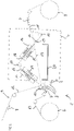
- FIG 1 shows a device 1 for laminating a substrate with a thermoplastic film.
- the thermoplastic film is denoted by the reference number 11, the substrate by the reference number 12 and the already laminated substrate by the reference number 13.
- the device 1 comprises a laminating unit 2, which in particular has a number of rollers 3 for pressing the film 11 onto the substrate 12.
- the device 1 also includes a feed device 4 for the thermoplastic film 11 to the laminating unit 2.
- the film 11 is unrolled from an unwinder 5 and transported to the laminating unit 2 by means of the feed device 4, after which the coated substrate 13 is rolled up by the winder 6 .
- the feed device 4 has a number of rollers 10 that can be driven in an adjustable manner. In the embodiment shown, three driven rollers 10 are shown. However, this representation is only an example and more or less driven rollers can also be provided.
- the feed device 4 includes additional cylinders or rollers, which are used to guide and deflect the film 11 and are only shown as an example and are not described in more detail.
- the thermoplastic film 11 is transported in the direction of the arrow 7 to the laminating unit 2 by means of the driven rollers 10 .
- the substrate 12 is in the embodiment shown also transported by means of a suitable feed device 9 along the arrow 8 to the laminating plant 2. After lamination, the laminated substrate 13 is transported to the reel 6 along the arrow 7 .
- the film 11 is largely guided without contact. Only in the area of the rollers 10 is the foil 11 selectively guided or supported. The foil 11 is not supported between the rollers 10 . It thus has a tension which is due in particular to the force of gravity acting on it and to the rotational speeds of the rollers 10 .
- thermoplastic film 11 is guided between the rollers 10 past devices 14 for heating a first side 16 of the film 11 and devices 15 for cooling a second side 17 of the film 11.
- the devices 14 for heating and the devices 15 for cooling are only shown here as examples. The number and arrangement of the devices 14 for heating and the devices 15 for cooling can vary.
- the heating of the first side 16 causes the thermoplastic film 11 to soften or partially melt on its first side 16 so that it can be connected to the substrate 12 in the laminating unit 2 .
- the cooling of the second side 17 serves to prevent the film 11 from melting completely and to maintain a certain stability, which is required for the transport process to the laminating plant 2 .
- the cooling thus partially compensates for the heat introduced. In particular, it can compensate for the waste heat if the heating devices are in the form of infrared radiators.
- the foil 11 is guided at a distance from the devices 14 for heating and the devices 15 for cooling and thus does not come into direct contact with cooled surfaces.
- the feed device 4 has an alternative feed path for a film to the laminating unit 2, which in figure 1 is indicated by a dashed line 19 and which does not bypass the devices 14 for heating and 15 for cooling.
- the alternative route can be used for a film that is not made of a thermoplastic material or should not be heated or cooled for other reasons.
- the device 1 also includes a trough 20 for collecting condensate that forms on the devices 15 for cooling due to the humid room air.
- the trough 20 is arranged below the cooling devices 15 so that condensate flows off the cooling devices 15 by gravity and drips into the trough 20 . In this way, the condensate does not pass any further elements of the feed device 4, in particular not the devices 14 for heating or the film web, which could be damaged by the condensate.
- the trough 20 is thus placed in such a way that condensate that forms on the devices 15 can drip directly into the trough 20 .
- the discharge of the condensate ensures that no condensate comes into contact with the film 11, which could result in quality losses of the surface.
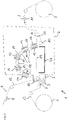
- figure 2 shows a second embodiment of a device 1 for laminating a substrate with a thermoplastic film.
- This device 1 differs from that in figure 1 shown embodiment characterized in that several driven rollers 10 are provided, which lead the film 11 on a semicircular path.
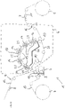
- figure 3 shows a third embodiment of the device 1 for laminating a substrate with a thermoplastic film 11.
- This embodiment differs from the previously shown in that several driven rollers 10 are arranged one above the other, so that the film 11 is guided vertically in sections.
- two devices 14 for heating and two devices for cooling 15 are also arranged one above the other.
- the devices 15 for cooling are arranged one above the other, but not above devices 14 for heating, so that no condensate can drip onto the devices 14 for heating.
- a trough 20 for collecting condensate is again provided immediately below the lower device 15 for cooling.
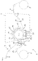
- FIG 4 shows a fourth embodiment of the device 1 for laminating a substrate 12 with a thermoplastic film 11.
- This embodiment differs from the previously shown ones in that the film 11 is guided in the feed device 4 on a conveyor belt 26 by means of non-driven rollers 25.
- the conveyor belt 26 is guided at a distance from the devices 15 for cooling.
- the trough 20 for collecting the condensate is arranged between the devices 15 for cooling and other elements of the feed device 4 in such a way that the condensate drips directly into the trough 20 and does not come into contact with other elements.
- FIG 5 shows a fifth embodiment of the device 1 for laminating a substrate 12 with a thermoplastic film 11.
- This embodiment differs from the ones previously shown in that the film 11 is partially not guided in the feed device 4 without contact, but by means of a cooled roller 21.
- the Foil 11 thus lies with its second side 17 in places on the surface of the cooled roll 21 .
- the speed of the cooled roller 21 can also be regulated.
- strippers 22 are provided, which strip off the condensate formed on the cooled roll 21 from the roll 21 and allow it to drip into the trough 20 .
- the scrapers 22 are arranged in the area of an underside 23 of the roller 21, while the film 11 is guided on the upper side 24 of the roller 21. In this way it is avoided that the foil 11 comes into contact with condensate on the surface of the roller 21, which could cause quality losses of the foil surface.
- the driven roller 10 just before the cooled roller 21 enables the web tension of the foil 11 to be regulated, for example in response to a decreasing tension due to the heating of the foil 11.
Landscapes
- Engineering & Computer Science (AREA)
- Mechanical Engineering (AREA)
- Physics & Mathematics (AREA)
- Health & Medical Sciences (AREA)
- Oral & Maxillofacial Surgery (AREA)
- Thermal Sciences (AREA)
- Quality & Reliability (AREA)
- Robotics (AREA)
- Lining Or Joining Of Plastics Or The Like (AREA)
- Laminated Bodies (AREA)
Abstract
- ein Kaschierwerk (2) zum Kaschieren des Substrats (12) mit der thermoplastischen Folie (11),
- eine Zuführeinrichtung (4) für die thermoplastische Folie (11) zum Kaschierwerk (2),
wobei die Zuführeinrichtung (4) für die thermoplastische Folie (11) Einrichtungen (14) zum Heizen einer ersten Seite (16) der Folie (11) und Einrichtungen (15) zum Kühlen einer zweiten Seite (17) der Folie (11) aufweist sowie eine Einrichtung (20) zum Auffangen von an den Einrichtungen (15) zum Kühlen entstehendem Kondensat.
Description
- Die vorliegende Erfindung betrifft ein Verfahren sowie eine Vorrichtung zum kontinuierlichen Kaschieren eines Substrats mit einem thermoplastischen Beschichtungsmaterial, insbesondere einer Folie. Bei dem Substrat kann es sich dabei ebenfalls um eine Folie handeln. Es kann sich jedoch auch um einen festen Körper aus Kunststoff, Metall oder einem anderen Material handeln.
- Es sind verschiedene Verfahren zum Kaschieren von Substraten mit einer thermoplastischen Folie bekannt. Die
EP 3 183 117 B1 beschreibt ein Verfahren sowie eine Vorrichtung zum Verkleben von zwei folienförmigen Substraten, wobei zumindest die eine Folie auf einem Förderband derart an einer Kühl- und Heizeinrichtung vorbeigeführt wird, dass die eine Seite der Folie gekühlt, die andere jedoch geheizt wird. - Die
EP 3 526 042 B1 offenbart ein ähnliches Verfahren, bei dem jedoch die eine Folie auf einer gekühlten Walze geführt und anschließend auch auf dieser Walze mit der zweiten Folie verbunden wird. - Wie sich herausgestellt hat, kommt es häufig zu Qualitätsminderungen in der Oberfläche der Folie, die Probleme beim Kaschieren verursachen.
- Es ist daher eine Aufgabe der vorliegenden Erfindung, eine Vorrichtung und ein Verfahren zum Kaschieren eines Substrats mit einer thermoplastischen Folie anzugeben, die die genannten Nachteile nicht aufweisen.
- Diese Aufgabe wird gelöst mit dem Gegenstand der unabhängigen Patentansprüche. Vorteilhafte Ausgestaltungen und Weiterentwicklungen sind Gegenstand der Unteransprüche.
- Gemäß einem Aspekt der Erfindung wird eine Vorrichtung zum Kaschieren eines Substrats mit einer thermoplastischen Folie angegeben, wobei die Vorrichtung ein Kaschierwerk zum Kaschieren des Substrats mit der thermoplastischen Folie aufweist sowie eine Zuführeinrichtung für die thermoplastische Folie zum Kaschierwerk. Die Zuführeinrichtung für die thermoplastische Folie weist Einrichtungen zum Heizen einer ersten Seite der Folie und Einrichtungen zum Kühlen einer zweiten Seite der Folie auf. Ferner weist sie eine Einrichtung zum Auffangen von an den Einrichtungen zum Kühlen entstehendem Kondensat auf.
- Unter einem Kaschierwerk wird hier und im Folgenden eine Vorrichtung verstanden, die das Beschichten, insbesondere durch Zuhilfenahme von Druck, des Substrats mit der thermoplastischen Folie durchführt. Typischerweise sind hierfür Walzen vorgesehen, durch die die beiden Folien geführt sind, falls das Substrat als Folie ausgebildet ist. Falls das Substrat nicht als Folie ausgebildet ist, umfasst das Kaschierwerk häufig ebenfalls zumindest eine Walze, mittels der die thermoplastische Folie auf das Substrat gebracht wird.
- Die Vorrichtung weist den Vorteil auf, dass an den Einrichtungen zum Kühlen sich bildendes Kondensat aufgefangen und gegebenenfalls abgeführt wird und nicht mit der Oberfläche der Folie in Berührung kommt. Somit können Schädigungen der Folienoberfläche durch Kondensat vermieden werden.
- Zu Schädigungen der Folienoberfläche kann es kommen, wenn Kondensat in direkten Kontakt mit der Folie kommt. Dies ist beispielsweise der Fall, wenn die Folie mit ihrer zweiten Seite Kontakt zu einem Kühlkörper hat, beispielsweise zu einem gekühlten Förderband oder einer gekühlten Walze. Zudem kann es zu Schäden an der Folie oder an Anlagenteilen kommen, wenn Kondensat auf sie herabtropft. Durch das Entfernen des Kondensats wird dies verhindert.
- Eine weitere Möglichkeit, einen Kontakt des Kondensats mit der Folie zu verhindern, ist, die Folie beabstandet von den Einrichtungen zum Kühlen zu führen. Dies bedeutet insbesondere, dass die Folie nicht mit gekühlten Oberflächen in direktem Kontakt steht. In diesem Fall sind ein Auffangen und eine Entfernung von Kondensat nicht in jedem Fall erforderlich, können jedoch trotzdem vorgesehen sein, beispielsweise, um ein Herabtropfen von Kondensat auf die Einrichtungen zum Heizen oder andere Anlagenteile zu verhindern.
- Beide Möglichkeiten zur Vermeidung eines Kontaktes zwischen Folie und Kondensat können auch miteinander kombiniert werden.
- Die Vorrichtung zum Kaschieren des Substrats mit einer thermoplastischen Folie kann darüber hinaus auch eine Zuführeinrichtung für das Substrat aufweisen, deren Ausgestaltung von der Art des Substrats abhängt. Als Einrichtungen zum Heizen der Folie können insbesondere Infrarotstrahler vorgesehen sein, jedoch auch andere Wärmequellen wie beispielsweise Laser. Zum Kühlen können beispielsweise gekühlte Bleche vorgesehen sein.
- Die Einrichtung zum Auffangen von an den Einrichtungen zum Kühlen entstehendem Kondensat kann insbesondere wannenartig ausgebildet sein. Bei der Anordnung der Einrichtung zum Auffangen von an den Einrichtungen zum Kühlen entstehendem Kondensat wird berücksichtigt, wohin das Kondensat tropft. Insbesondere wird die Einrichtung zum Auffangen von Kondensat derart angeordnet, dass kein Kondensat auf die Folie oder empfindliche Anlagenteile gelangen kann.
- Die Einrichtung zum Auffangen kann auch mehrere einzelne Elemente aufweisen, beispielsweise mehrere wannenartige Einrichtungen. Diese können auch ergänzt werden durch Einrichtungen, die das Kondensat von den kühlen Oberflächen entfernen, beispielsweise Abstreifern, die an den Oberflächen entlangstreifen, das Kondensat abnehmen und es der Wanne zuführen.
- Gemäß einer Ausführungsform umfasst somit die Einrichtung zum Auffangen von Kondensat zumindest eine Vorrichtung zum Abstreifen von Kondensat von Oberflächen der Einrichtungen zum Kühlen. Bei dieser Ausführungsform können Oberflächen, an denen sich Kondensat bildet, nach der Entfernung dieses Kondensats mit der Folie in Kontakt gebracht werden, ohne dass die Gefahr einer Beschädigung der Folie besteht.
- Gemäß einer Ausführungsform sind die Einrichtungen zum Kühlen unterhalb oder neben den Einrichtungen zum Heizen angeordnet. Auf diese Weise wird schon baulich vermieden, dass Kondensat auf die Einrichtungen zum Heizen herabtropfen kann.
- Die Vorrichtung kann ferner eine Anzahl steuerbar angetriebener Walzen aufweisen, über die die Folie an den Einrichtungen zum Heizen und den Einrichtungen zum Kühlen vorbeigeführt ist, wobei eine Spannung der Folie über die Geschwindigkeit der angetriebenen Walzen regelbar ist.
- Diese Ausführungsform weist den Vorteil auf, dass sie eine praktisch berührungslose Führung der thermoplastischen Folie mittels der steuerbar angetriebenen Walzen ermöglicht. Die Folie liegt demnach in der Zuführeinrichtung nicht flächig auf einem Förderband oder einer Walze mit großem Durchmesser oder einer anderen Oberfläche auf, sondern wird lediglich von den steuerbar angetriebenen Walzen punktuell unterstützt und gefördert und gegebenenfalls umgelenkt und ansonsten berührungslos geführt. Da die Drehgeschwindigkeit der angetriebenen Walzen steuerbar, insbesondere sogar regelbar ist, können Spannungen innerhalb der Folie durch den Aufbau von Geschwindigkeitsdifferenzen zwischen einzelnen Walzen ausgeglichen werden. Verliert beispielsweise die geführte Folie an Spannung, so kann eine Geschwindigkeitsdifferenz zwischen zwei Walzen derart eingestellt werden, dass die Folie wieder gespannt wird. Dies ist insbesondere vorteilhaft, da die Erwärmung der thermoplastischen Folie sowohl eine Ausdehnung als auch eine Aufweichung der Folie bewirkt.
- Zudem hat die praktisch berührungslose Führung der Folie den Vorteil, dass diese besonders effizient erhitzt bzw. gekühlt werden kann.
- Gemäß einer Ausführungsform sind angetriebene Walzen in Bewegungsrichtung der Folie in Förderrichtung der Folie zumindest vor und/oder hinter den Einrichtungen zum Kühlen und Heizen angeordnet, d.h. sie führen die Folie unmittelbar bevor diese die Einrichtungen zum Heizen und zum Kühlen durchläuft. Diese Ausführungsform hat den Vorteil, dass Längenänderungen der thermoplastischen Folie, die durch das Aufheizen bzw. Kühlen der Folie verursacht wurden, über eine Geschwindigkeitsregelung der Walzen ausgeglichen werden können.
- Gemäß einer alternativen Ausführungsform ist die Folie zumindest abschnittsweise mittels eines Förderbandes geführt, auf dem sie aufliegt.
- Die thermoplastische Folie ist insbesondere beabstandet zu den Einrichtungen zum Heizen geführt. Somit kommt die thermoplastische Folie nicht in Kontakt mit Elementen der Einrichtungen zum Heizen.
- Die Einrichtungen zum Kühlen können zumindest eine gekühlte Walze umfassen, über die die Folie geführt ist. Alternativ kann die thermoplastische Folie beabstandet zu den Einrichtungen zum Kühlen geführt sein. Im letzteren Fall sind die Einrichtungen zum Kühlen entlang der zwischen den Walzen gespannten Folienbahn in der Zuführeinrichtung angeordnet, jedoch nicht auf derselben Seite der Folie wie die Einrichtungen zum Heizen, sondern auf der gegenüberliegenden Seite.
- Wird die thermoplastische Folie beabstandet zu den Einrichtungen zum Kühlen geführt, hat dies den Vorteil, dass die Folie nicht mit Oberflächen in Berührung kommt, auf denen sich Kondensat bildet.
- Gemäß einer Ausführungsform sind zwischen den Einrichtungen zum Heizen und der thermoplastischen Folie Gitter zum Schutz der Einrichtungen zum Heizen vor einem Kontakt mit der Folie angeordnet. Derartige Gitter haben den Vorteil, dass sie einen Kontakt zwischen der thermoplastischen Folie und den Einrichtungen zum Heizen verhindern. Als zusätzliche Sicherung kann die Zuführeinrichtung zumindest eine Einrichtung zur Erzeugung eines Luftstroms zwischen der thermoplastischen Folie und den Einrichtungen zum Heizen aufweisen.
- Die Einrichtung zur Erzeugung eines Luftstroms kann als Gebläse, Druckluftquelle oder auch als Unterdruckquelle ausgebildet sein. Sie hat den Vorteil, dass bei zu geringer Bahnspannung der Folie oder im Falle eines Bahnrisses ein Ankleben der Folie am Gitter bzw. an der Heizvorrichtung vermieden wird. Dazu kann es vorgesehen sein, dass die Einrichtung zur Erzeugung eines Luftstroms bei Verlust der Bahnspannung automatisch und/oder manuell eingeschaltet wird. Dabei kann sie beispielsweise Kaltluft zwischen die Einrichtung zum Heizen und die Folie bzw. das Gitter einblasen. Ist ein Gitter vorgesehen, so entweicht die Luft durch das Gitter und bläst die Folie von den Einrichtungen zum Heizen weg.
- Für die Anordnung der angetriebenen Walzen und gegebenenfalls weiterer Walzen oder Umlenkrollen bzw. des Förderbandes der Zuführeinrichtung gibt es verschiedene Möglichkeiten. Beispielsweise kann die thermoplastische Folie in der Zuführeinrichtung zumindest abschnittsweise senkrecht nach oben und/oder nach unten geführt sein. Sie kann jedoch auch zumindest abschnittsweise schräg nach oben und/oder nach unten geführt sein. Zudem kann die thermoplastische Folie zumindest abschnittsweise auf einem Kreisbogen geführt sein. Welche Anordnung gewählt wird, kann unter anderem von dem vorhandenen Platz und anderen praktischen Überlegungen abhängen.
- Gemäß einer Ausführungsform weist die Zuführeinrichtung einen alternativen Zuführweg für die Folie auf, der keine Einrichtungen zum Heizen und keine Einrichtungen zu Kühlen umfasst. Auf diesem alternativen Zuführweg wird die Folie dem Kaschierwerk somit zugeführt, ohne dass sie geheizt wird. Der alternative Zuführweg kann beispielsweise verwendet werden, wenn keine thermoplastische Folie zum Kaschieren verwendet wird, sondern ein anderes Material, bzw. wenn die Verbindung zwischen der Folie und dem Substrat auf eine andere Weise, beispielsweise mittels eines separat aufgetragenen Klebstoffs, erfolgt. Insbesondere, wenn auf einer Anlage verschiedene Verfahren gleichzeitig oder abwechselnd zum Einsatz kommen sollen, ist das Vorhandensein des alternativen Zuführwegs von Vorteil.
- Gemäß einem weiteren Aspekt der Erfindung wird ein Verfahren zum Kaschieren eines Substrats mit einer thermoplastischen Folie angegeben, wobei das Verfahren das Zuführen der Folie zu einem Kaschierwerk umfasst, wobei die Folie während des Zuführens auf einer ersten Seite beheizt und auf einer zweiten Seite gekühlt wird, wobei ein sich an Einrichtungen zum Kühlen bildendes Kondensat aufgefangen und gegebenenfalls abgeführt wird, so dass es nicht mit der Folie in Kontakt kommt.
- Alternativ zum Auffangen und gegebenenfalls Abführen des Kondensats kann es vorgesehen sein, dass die Folie beabstandet von den Einrichtungen zum Kühlen geführt ist und somit nicht direkt mit gekühlten Oberflächen in Kontakt kommt.
- Gemäß einer Ausführungsform erfolgt das Zuführen mittels einer Anzahl steuerbar angetriebener Walzen, über die die Folie geführt wird, wobei während des Zuführens eine Spannung der Folie über die Geschwindigkeit der angetriebenen Walzen gesteuert und insbesondere auch geregelt wird.
- Insbesondere kann eine abschnittsweise Regelung der Geschwindigkeit in der Zuführeinrichtung vorgesehen sein, die durch eine individuelle Regelbarkeit der angetriebenen Walzen ermöglicht wird. Wenn die Walzen unabhängig voneinander in ihrer Geschwindigkeit regelbar sind, ist es möglich, zwischen aufeinanderfolgenden Walzen Differenzgeschwindigkeiten einzustellen, über die eine Spannung in der Folie auf- oder abgebaut werden kann.
- Dem Kaschierwerk wird ferner das Substrat zugeführt, das in Form einer Folie oder in anderer Form vorliegen kann.
- Gemäß einer Ausführungsform wird die Folie durch einen in einen Zwischenraum zwischen der Folie und den Einrichtungen zum Heizen eingeblasenen Luftstrom auf Abstand von den Einrichtungen zum Heizen gehalten. Dazu kann insbesondere vorgesehen sein, dass in den Zwischenraum eingeblasene Luft durch Öffnungen in einem Gitter austritt und die Folie von den Einrichtungen zum Heizen wegbläst.
- Ausführungsformen der Erfindung werden im Folgenden anhand von schematischen Figuren näher erläutert.
- Figur 1
- zeigt schematisch eine Vorrichtung zum Kaschieren eines Substrats mit einer thermoplastischen Folie gemäß einer ersten Ausführungsform der Erfindung;
- Figur 2
- zeigt schematisch eine Vorrichtung zum Kaschieren eines Substrats mit einer thermoplastischen Folie gemäß einer zweiten Ausführungsform der Erfindung;
- Figur 3
- zeigt schematisch eine Vorrichtung zum Kaschieren eines Substrats mit einer thermoplastischen Folie gemäß einer dritten Ausführungsform der Erfindung;
- Figur 4
- zeigt schematisch eine Vorrichtung zum Kaschieren eines Substrats mit einer thermoplastischen Folie gemäß einer vierten Ausführungsform der Erfindung und
- Figur 5
- zeigt schematisch eine Vorrichtung zum Kaschieren eines Substrats mit einer thermoplastischen Folie gemäß einer fünften Ausführungsform der Erfindung.
-
Figur 1 zeigt eine Vorrichtung 1 zum Kaschieren eines Substrats mit einer thermoplastischen Folie. In derFigur 1 ist die thermoplastische Folie mit dem Bezugszeichen 11 bezeichnet, das Substrat mit dem Bezugszeichen 12 und das bereits kaschierte Substrat mit dem Bezugszeichen 13. - Die Vorrichtung 1 umfasst ein Kaschierwerk 2, das insbesondere eine Anzahl von Walzen 3 zum Andrücken der Folie 11 an das Substrat 12 aufweist. Ferner umfasst die Vorrichtung 1 eine Zuführeinrichtung 4 für die thermoplastische Folie 11 zu dem Kaschierwerk 2. Die Folie 11 wird dabei von einem Abroller 5 abgerollt und mittels der Zuführeinrichtung 4 zu dem Kaschierwerk 2 transportiert, wonach das beschichtete Substrat 13 durch den Aufroller 6 aufgerollt wird.
- Die Zuführeinrichtung 4 weist eine Anzahl regelbar angetriebener Walzen 10 auf. In der gezeigten Ausführungsform sind drei angetriebene Walzen 10 dargestellt. Diese Darstellung ist jedoch nur beispielhaft und es können auch mehr oder weniger angetriebene Walzen vorgesehen sein.
- Die Zuführeinrichtung 4 umfasst weitere Walzen oder Rollen, die zur Führung und Umlenkung der Folie 11 dienen und lediglich beispielhaft gezeigt und nicht näher bezeichnet sind. Die thermoplastische Folie 11 wird mittels der angetriebenen Walzen 10 in Richtung des Pfeils 7 zu dem Kaschierwerk 2 transportiert. Das Substrat 12 wird in der gezeigten Ausführungsform ebenfalls mittels einer geeigneten Zuführeinrichtung 9 entlang des Pfeils 8 zu dem Kaschierwerk 2 transportiert. Nach dem Kaschieren wird das kaschierte Substrat 13 entlang des Pfeils 7 zu dem Aufroller 6 transportiert.
- Die Folie 11 wird größtenteils berührungslos geführt. Lediglich im Bereich der Walzen 10 wird die Folie 11 punktuell geführt bzw. unterstützt. Zwischen den Walzen 10 ist die Folie 11 nicht unterstützt. Sie weist somit eine Spannung auf, die insbesondere durch die auf sie wirkende Schwerkraft und durch die Drehgeschwindigkeiten der Walzen 10 bedingt ist.
- Entlang ihres Weges durch die Zuführeinrichtung 4 wird die thermoplastische Folie 11 zwischen den Walzen 10 an Einrichtungen 14 zum Heizen einer ersten Seite 16 der Folie 11 und Einrichtungen 15 zum Kühlen einer zweiten Seite 17 der Folie 11 vorbeigeführt. Auch die Einrichtungen 14 zum Heizen und die Einrichtungen 15 zum Kühlen sind hier lediglich beispielhaft dargestellt. Die Anzahl und Anordnung der Einrichtungen 14 zum Heizen und der Einrichtungen 15 zum Kühlen können variieren.
- Das Beheizen der ersten Seite 16 bewirkt ein Erweichen bis teilweises Aufschmelzen der thermoplastischen Folie 11 an ihrer ersten Seite 16, sodass sich diese in dem Kaschierwerk 2 mit dem Substrat 12 verbinden kann. Die Kühlung der zweiten Seite 17 dient dazu, die Folie 11 nicht vollständig aufschmilzen zu lassen und eine gewisse Stabilität zu erhalten, die für den Transportprozess zum Kaschierwerk 2 erforderlich ist. Somit kompensiert die Kühlung die eingebrachte Wärme teilweise. Insbesondere kann sie die Abwärme kompensieren, falls die Einrichtungen zum Heizen als Infrarotstrahler ausgebildet sind.
- Die Folie 11 wird von den Einrichtungen 14 zum Heizen und den Einrichtungen 15 zu Kühlen beabstandet geführt und kommt somit nicht in direkten Kontakt mit gekühlten Oberflächen. Zwischen den Einrichtungen zum Heizen 14 und der Folie 11 sind Gitter 18 angeordnet, die ein Anhaften der Folie 11 an den Einrichtungen 14 zum Heizen verhindern sollen.
- Die Zuführeinrichtung 4 weist einen alternativen Zuführweg für eine Folie zu dem Kaschierwerk 2 auf, der in
Figur 1 durch eine gestrichelte Linie 19 angedeutet ist und der nicht an den Einrichtungen 14 zum Heizen und 15 zum Kühlen vorbeigeführt wird. Der alternative Weg kann für eine Folie genutzt werden, die nicht aus einem thermoplastischen Material besteht oder aus anderen Gründen nicht geheizt bzw. gekühlt werden soll. - Die Vorrichtung 1 umfasst ferner eine Wanne 20 zum Auffangen von Kondensat, das sich aufgrund der feuchten Raumluft an den Einrichtungen 15 zum Kühlen bildet. Die Wanne 20 ist unterhalb der Einrichtungen 15 zum Kühlen angeordnet, sodass Kondensat der Schwerkraft folgend von den Einrichtungen 15 zum Kühlen abfließt und in die Wanne 20 tropft. Auf diesem Weg passiert das Kondensat keine weiteren Elemente der Zuführeinrichtung 4, insbesondere nicht die Einrichtungen 14 zum Heizen oder die Folienbahn, die durch das Kondensat beschädigt werden könnten. Die Wanne 20 ist somit derart platziert, dass sich an den Einrichtungen 15 bildendes Kondensat unmittelbar in die Wanne 20 tropfen kann. Durch die Abführung des Kondensats wird erreicht, dass kein Kondensat mit der Folie 11 in Berührung kommt, was Qualitätseinbußen der Oberfläche zur Folge haben könnte.
-
Figur 2 zeigt eine zweite Ausführungsform einer Vorrichtung 1 zum Kaschieren eines Substrats mit einer thermoplastischen Folie. Diese Vorrichtung 1 unterscheidet sich von der inFigur 1 gezeigten Ausführungsform dadurch, dass mehrere angetriebene Walzen 10 vorgesehen sind, die die Folie 11 auf einer Halbkreisbahn führen. -
Figur 3 zeigt eine dritte Ausführungsform der Vorrichtung 1 zum Kaschieren eines Substrats mit einer thermoplastischen Folie 11. Diese Ausführungsform unterscheidet sich von den vorher gezeigten dadurch, dass mehrere angetriebene Walzen 10 übereinander angeordnet sind, sodass die Folie 11 abschnittsweise vertikal geführt ist. In der gezeigten Ausführungsform sind auch jeweils zwei Einrichtungen 14 zum Heizen und zwei Einrichtungen zum Kühlen 15 übereinander angeordnet. - Diese Anordnung ist besonders platzsparend und auch auf kleinem Bauraum zu verwirklichen. Die Einrichtungen 15 zum Kühlen sind in diese Ausführungsform übereinander angeordnet, jedoch nicht oberhalb von Einrichtungen 14 zum Heizen, damit kein Kondensat auf die Einrichtungen 14 zum Heizen tropfen kann. Unmittelbar unterhalb der unteren Einrichtung 15 zum Kühlen ist wiederum eine Wanne 20 zum Auffangen von Kondensat vorgesehen.
-
Figur 4 zeigt eine vierte Ausführungsform der Vorrichtung 1 zum Kaschieren eines Substrats 12 mit einer thermoplastischen Folie 11. Diese Ausführungsform unterscheidet sich von den vorher gezeigten dadurch, dass die Folie 11 in der Zuführeinrichtung 4 auf einem Förderband 26 mittels nicht angetriebener Walzen 25 geführt ist. Das Förderband 26 ist beabstandet von den Einrichtungen 15 zum Kühlen geführt. Die Wanne 20 zum Auffangen des Kondensats ist dabei derart zwischen den Einrichtungen 15 zum Kühlen und weiteren Elementen der Zuführeinrichtung 4 angeordnet, dass das Kondensat unmittelbar in die Wanne 20 tropft und nicht mit weiteren Elementen in Berührung kommt. -
Figur 5 zeigt eine fünfte Ausführungsform der Vorrichtung 1 zum Kaschieren eines Substrats 12 mit einer thermoplastischen Folie 11. Diese Ausführungsform unterscheidet sich von den vorher gezeigten dadurch, dass die Folie 11 in der Zuführeinrichtung 4 teilweise nicht berührungslos geführt ist, sondern mittels einer gekühlten Walze 21. Die Folie 11 liegt somit mit ihrer zweiten Seite 17 stellenweise auf der Oberfläche der gekühlten Walze 21 auf. Die gekühlte Walze 21 kann ebenfalls in ihrer Geschwindigkeit regelbar angetrieben sein. - Bei dieser Ausführungsform sind Abstreifer 22 vorgesehen, die an der gekühlten Walze 21 entstehendes Kondensat von der Walze 21 abstreifen und in die Wanne 20 tropfen lassen. Dabei sind die Abstreifer 22 im Bereich einer Unterseite 23 der Walze 21 angeordnet, während die Folie 11 auf der Oberseite 24 der Walze 21 geführt ist. Auf diese Weise wird vermieden, dass die Folie 11 mit Kondensat auf der Oberfläche der Walze 21 in Berührung kommt, was Qualitätseinbußen der Folienoberfläche bewirken könnte.
- Die angetriebene Walze 10 kurz vor der gekühlten Walze 21 ermöglicht eine Regelung der Bahnspannung der Folie 11, beispielsweise in Reaktion auf eine nachlassende Spannung wegen des Aufheizens der Folie 11.
-
- 1
- Vorrichtung
- 2
- Kaschierwerk
- 3
- Walze
- 4
- Zuführeinrichtung
- 5
- Abroller
- 6
- Aufroller
- 7
- Pfeil
- 8
- Pfeil
- 9
- Zuführeinrichtung
- 10
- Walze
- 11
- Folie
- 12
- Substrat
- 13
- kaschiertes Substrat
- 14
- Einrichtung zum Heizen
- 15
- Einrichtung zum Kühlen
- 16
- erste Seite
- 17
- zweite Seite
- 18
- Gitter
- 19
- gestrichelte Linie
- 20
- Wanne
- 21
- Walze
- 22
- Abstreifer
- 23
- Unterseite
- 24
- Oberseite
- 25
- Walze
- 26
- Förderband
Claims (15)
- Vorrichtung (1) zum Kaschieren eines Substrats (12) mit einer thermoplastischen Folie (11), wobei die Vorrichtung (1) folgendes aufweist:- ein Kaschierwerk (2) zum Kaschieren des Substrats (12) mit der thermoplastischen Folie (11),- eine Zuführeinrichtung (4) für die thermoplastische Folie (11) zum Kaschierwerk (2), wobei die Zuführeinrichtung (4) für die thermoplastische Folie (11) Einrichtungen (14) zum Heizen einer ersten Seite (16) der Folie (11) und Einrichtungen (15) zum Kühlen einer zweiten Seite (17) der Folie (11) aufweist sowie eine Einrichtung (20) zum Auffangen von an den Einrichtungen (15) zum Kühlen entstehendem Kondensat.
- Vorrichtung (1) nach Anspruch 1,
wobei die Einrichtungen (15) zum Kühlen zumindest eine gekühlte Walze (21) umfassen, über die die Folie (11) geführt ist. - Vorrichtung (1) nach Anspruch 1,
wobei die thermoplastische Folie (11) beabstandet zu den Einrichtungen (15) zum Kühlen geführt ist. - Vorrichtung nach einem der Ansprüche 1 bis 3,
wobei die Einrichtung (20) zum Auffangen von Kondensat zumindest eine Vorrichtung zum Abstreifen von Kondensat von Oberflächen der Einrichtungen (15) zum Kühlen umfasst. - Vorrichtung (1) zum Kaschieren eines Substrats (12) mit einer thermoplastischen Folie (11), wobei die Vorrichtung (1) folgendes aufweist:- ein Kaschierwerk (2) zum Kaschieren des Substrats (12) mit der thermoplastischen Folie (11),- eine Zuführeinrichtung (4) für die thermoplastische Folie (11) zum Kaschierwerk (2), wobei die Zuführeinrichtung (4) für die thermoplastische Folie (11) Einrichtungen (14) zum Heizen einer ersten Seite (16) der Folie (11) und Einrichtungen (15) zum Kühlen einer zweiten Seite (17) der Folie (11) aufweist und die Folie (11) beabstandet von den Einrichtungen (15) zum Kühlen geführt ist.
- Vorrichtung (1) nach einem der Ansprüche 1 bis 5,
ferner umfassend eine Anzahl steuerbar angetriebener Walzen (10), über die die Folie (11) an den Einrichtungen (14) zum Heizen und den Einrichtungen (15) zum Kühlen vorbei geführt ist, wobei eine Spannung der Folie (11) über die Geschwindigkeit der angetriebenen Walzen (10) regelbar ist. - Vorrichtung (1) nach einem der Ansprüche 1 bis 6,
ferner umfassend ein Förderband (26), auf dem die Folie (11) zumindest abschnittsweise geführt ist. - Vorrichtung (1) nach einem der Ansprüche 1 bis 7,
wobei zwischen den Einrichtungen (14) zum Heizen und der thermoplastischen Folie (11) Gitter (18) zum Schutz der Einrichtungen (14) zum Heizen vor einem Kontakt mit der Folie (11) angeordnet sind. - Vorrichtung (1) nach einem der Ansprüche 1 bis 8,
wobei die Zuführeinrichtung (4) zumindest eine Einrichtung zur Erzeugung eines Luftstroms zwischen der thermoplastischen Folie (11) und den Einrichtungen (14) zum Heizen aufweist. - Vorrichtung (1) nach einem der Ansprüche 1 bis 9,
wobei die thermoplastische Folie (11) in der Zuführeinrichtung (4) zumindest abschnittsweise senkrecht nach oben und/oder nach unten und/oder abschnittsweise schräg nach oben und/oder nach unten und/oder abschnittsweise auf einem Kreisbogen geführt ist. - Vorrichtung (1) nach einem der Ansprüche 1 bis 10,
wobei die Zuführeinrichtung (4) einen alternativen Zuführweg für eine Folie (11) aufweist, der keine Einrichtungen (14) zum Heizen und keine Einrichtungen (15) zum Kühlen umfasst. - Verfahren zum Kaschieren eines Substrats (12) mit einer thermoplastischen Folie (11), wobei das Verfahren das Zuführen der Folie (11) zu einem Kaschierwerk (2) umfasst, wobei die Folie (11) während des Zuführens auf einer ersten Seite (16) beheizt und auf einer zweiten Seite (17) gekühlt wird, wobei ein sich an Einrichtungen (15) zum Kühlen bildendes Kondensat aufgefangen wird.
- Verfahren zum Kaschieren eines Substrats (12) mit einer thermoplastischen Folie (11), wobei das Verfahren das Zuführen der Folie (11) zu einem Kaschierwerk (2) umfasst, wobei die Folie (11) während des Zuführens auf einer ersten Seite (16) beheizt und auf einer zweiten Seite (17) gekühlt wird und die Folie (11) beabstandet von den Einrichtungen (15) zum Kühlen geführt wird.
- Verfahren nach Anspruch 12 oder 13,
wobei das Zuführen mittels einer Anzahl steuerbar angetriebener Walzen (10) erfolgt, über die die Folie (11) geführt wird, wobei während des Zuführens eine Spannung der Folie (11) über die Geschwindigkeit der angetriebenen Walzen (10) geregelt wird. - Verfahren nach einem der Ansprüche 12 bis 15,
wobei die Folie (11) durch einen in einen Zwischenraum zwischen der Folie (11) und den Einrichtungen (14) zum Heizen eingeblasenen Luftstrom auf Abstand von den Einrichtungen zum Heizen (14) gehalten wird.
Priority Applications (9)
| Application Number | Priority Date | Filing Date | Title |
|---|---|---|---|
| HUE20200967A HUE066406T2 (hu) | 2020-10-09 | 2020-10-09 | Berendezés és eljárás hordozóanyag hõre lágyuló fóliával történõ kasírozásához |
| PL20200967.6T PL3981599T3 (pl) | 2020-10-09 | 2020-10-09 | Urządzenie i sposób do laminowania podłoża folią termoplastyczną |
| EP20200967.6A EP3981599B1 (de) | 2020-10-09 | 2020-10-09 | Vorrichtung und verfahren zum kaschieren eines substrats mit einer thermoplastischen folie |
| ES20200967T ES2973496T3 (es) | 2020-10-09 | 2020-10-09 | Dispositivo y procedimiento para laminar un sustrato con una película termoplástica |
| KR1020237011654A KR20230084495A (ko) | 2020-10-09 | 2021-09-20 | 기재를 열가소성 필름과 적층하기 위한 디바이스 및 방법 |
| CN202180068844.8A CN116348299A (zh) | 2020-10-09 | 2021-09-20 | 用于将基材与热塑性膜进行层压的装置和方法 |
| JP2023521482A JP2023546024A (ja) | 2020-10-09 | 2021-09-20 | 熱可塑性フィルムで基材をラミネートするための装置および方法 |
| PCT/EP2021/075766 WO2022073750A1 (de) | 2020-10-09 | 2021-09-20 | Vorrichtung und verfahren zum kaschieren eines substrats mit einer thermoplastischen folie |
| US18/194,839 US12350861B2 (en) | 2020-10-09 | 2023-04-03 | Device and method for laminating a substrate with a thermoplastic film |
Applications Claiming Priority (1)
| Application Number | Priority Date | Filing Date | Title |
|---|---|---|---|
| EP20200967.6A EP3981599B1 (de) | 2020-10-09 | 2020-10-09 | Vorrichtung und verfahren zum kaschieren eines substrats mit einer thermoplastischen folie |
Publications (2)
| Publication Number | Publication Date |
|---|---|
| EP3981599A1 true EP3981599A1 (de) | 2022-04-13 |
| EP3981599B1 EP3981599B1 (de) | 2023-12-13 |
Family
ID=72826691
Family Applications (1)
| Application Number | Title | Priority Date | Filing Date |
|---|---|---|---|
| EP20200967.6A Active EP3981599B1 (de) | 2020-10-09 | 2020-10-09 | Vorrichtung und verfahren zum kaschieren eines substrats mit einer thermoplastischen folie |
Country Status (9)
| Country | Link |
|---|---|
| US (1) | US12350861B2 (de) |
| EP (1) | EP3981599B1 (de) |
| JP (1) | JP2023546024A (de) |
| KR (1) | KR20230084495A (de) |
| CN (1) | CN116348299A (de) |
| ES (1) | ES2973496T3 (de) |
| HU (1) | HUE066406T2 (de) |
| PL (1) | PL3981599T3 (de) |
| WO (1) | WO2022073750A1 (de) |
Citations (7)
| Publication number | Priority date | Publication date | Assignee | Title |
|---|---|---|---|---|
| DE2741428A1 (de) * | 1976-09-27 | 1978-04-06 | Gulf & Western Corp | Verfahren und vorrichtung zum bedrucken von duennem bzw. blattfoermigem material mit einem muster, insbesondere zum einpraegen eines musters |
| US5141583A (en) * | 1988-10-14 | 1992-08-25 | Kurt Held | Method of and apparatus for continuously fabricating laminates |
| DE3785338T2 (de) * | 1986-09-10 | 1993-10-21 | Astechnologies Inc | Vorrichtung und verfahren zur dampflaminierung. |
| US6337126B1 (en) * | 1994-08-04 | 2002-01-08 | Forbo International S.A. | Floor covering |
| DE202017006956U1 (de) * | 2017-08-25 | 2019-02-26 | Klomfass Gierlings & Partner GbR (vertretungsberechtigter Gesellschafter: Michael Gierlings 40723 Hilden) | Vorrichtung zum Kaschieren eines Substrates mit einem thermoplastischen Beschichtungsmaterial |
| EP3183117B1 (de) | 2014-08-21 | 2019-03-13 | Henkel AG & Co. KGaA | Verfahren und vorrichtung zum verkleben von zwei folienförmigen substraten |
| DE202020102523U1 (de) * | 2020-05-05 | 2020-07-06 | Klomfass Gierlings & Partner GbR (vertretungsberechtigter Gesellschafter Michael Gierlings,41564 Kaarst) | Kaschieranlage |
Family Cites Families (6)
| Publication number | Priority date | Publication date | Assignee | Title |
|---|---|---|---|---|
| JPS5848350B2 (ja) * | 1976-06-03 | 1983-10-27 | 凸版印刷株式会社 | ラミネ−ト方法 |
| US4923555A (en) * | 1986-09-10 | 1990-05-08 | Astechnologies, Inc. | Apparatus for steam lamination |
| JPH05309806A (ja) * | 1992-05-07 | 1993-11-22 | Sekisui Chem Co Ltd | 断熱シート体と金属板との積層装置 |
| US7303641B2 (en) * | 2002-12-03 | 2007-12-04 | Hunter Douglas Inc. | Method for fabricating cellular structural panels |
| JP5189424B2 (ja) * | 2008-07-10 | 2013-04-24 | 富士フイルム株式会社 | 塗布膜の乾燥方法 |
| JP7459116B2 (ja) * | 2019-01-11 | 2024-04-01 | ヘンケル・アクチェンゲゼルシャフト・ウント・コムパニー・コマンディットゲゼルシャフト・アウフ・アクチェン | フィルム状の基材を接着結合するための方法及び装置並びにそれにより得られる複合体 |
-
2020
- 2020-10-09 PL PL20200967.6T patent/PL3981599T3/pl unknown
- 2020-10-09 ES ES20200967T patent/ES2973496T3/es active Active
- 2020-10-09 EP EP20200967.6A patent/EP3981599B1/de active Active
- 2020-10-09 HU HUE20200967A patent/HUE066406T2/hu unknown
-
2021
- 2021-09-20 WO PCT/EP2021/075766 patent/WO2022073750A1/de not_active Ceased
- 2021-09-20 KR KR1020237011654A patent/KR20230084495A/ko active Pending
- 2021-09-20 JP JP2023521482A patent/JP2023546024A/ja active Pending
- 2021-09-20 CN CN202180068844.8A patent/CN116348299A/zh active Pending
-
2023
- 2023-04-03 US US18/194,839 patent/US12350861B2/en active Active
Patent Citations (9)
| Publication number | Priority date | Publication date | Assignee | Title |
|---|---|---|---|---|
| DE2741428A1 (de) * | 1976-09-27 | 1978-04-06 | Gulf & Western Corp | Verfahren und vorrichtung zum bedrucken von duennem bzw. blattfoermigem material mit einem muster, insbesondere zum einpraegen eines musters |
| DE3785338T2 (de) * | 1986-09-10 | 1993-10-21 | Astechnologies Inc | Vorrichtung und verfahren zur dampflaminierung. |
| US5141583A (en) * | 1988-10-14 | 1992-08-25 | Kurt Held | Method of and apparatus for continuously fabricating laminates |
| US6337126B1 (en) * | 1994-08-04 | 2002-01-08 | Forbo International S.A. | Floor covering |
| EP3183117B1 (de) | 2014-08-21 | 2019-03-13 | Henkel AG & Co. KGaA | Verfahren und vorrichtung zum verkleben von zwei folienförmigen substraten |
| DE202017006956U1 (de) * | 2017-08-25 | 2019-02-26 | Klomfass Gierlings & Partner GbR (vertretungsberechtigter Gesellschafter: Michael Gierlings 40723 Hilden) | Vorrichtung zum Kaschieren eines Substrates mit einem thermoplastischen Beschichtungsmaterial |
| WO2019038311A1 (de) * | 2017-08-25 | 2019-02-28 | Klomfass Gierling & Partner Gbr | Vorrichtung zum kaschieren eines substrates mit einem thermoplastischen beschichtungsmaterial |
| EP3526042B1 (de) | 2017-08-25 | 2020-05-27 | Klomfass Gierlings & Partner GBR | Vorrichtung zum kaschieren eines substrates mit einem thermoplastischen beschichtungsmaterial |
| DE202020102523U1 (de) * | 2020-05-05 | 2020-07-06 | Klomfass Gierlings & Partner GbR (vertretungsberechtigter Gesellschafter Michael Gierlings,41564 Kaarst) | Kaschieranlage |
Non-Patent Citations (1)
| Title |
|---|
| UNKNOWN: "Tension Control Complete Guide TENSION CONTROLLER ELECTROMAGNETIC CLUTCHES AND BRAKES", 31 December 2019 (2019-12-31), XP055784228, Retrieved from the Internet <URL:https://dl.mitsubishielectric.co.jp/dl/fa/document/catalog/clutch/sh-170011eng/sh170011-c.pdf> [retrieved on 20210310] * |
Also Published As
| Publication number | Publication date |
|---|---|
| WO2022073750A1 (de) | 2022-04-14 |
| KR20230084495A (ko) | 2023-06-13 |
| EP3981599B1 (de) | 2023-12-13 |
| US20230241807A1 (en) | 2023-08-03 |
| PL3981599T3 (pl) | 2024-05-06 |
| CN116348299A (zh) | 2023-06-27 |
| JP2023546024A (ja) | 2023-11-01 |
| US12350861B2 (en) | 2025-07-08 |
| HUE066406T2 (hu) | 2024-08-28 |
| ES2973496T3 (es) | 2024-06-20 |
Similar Documents
| Publication | Publication Date | Title |
|---|---|---|
| EP0640236B1 (de) | Etikettenbogen, verfahren zur herstellung und vorrichtung | |
| DE2604192C2 (de) | Luftunterstützte Blattablösung, insbesondere in einer Rollenschmelz- Fixiereinrichtung eines Kopiergerätes | |
| DE102007027987B3 (de) | Vorrichtung zur Aufnahme von plattenförmigen Materialien für zumindest einen Trennvorgang | |
| EP0986478B1 (de) | Verfahren zum Einziehen einer Teilpapierbahn | |
| EP2190796B1 (de) | Vorrichtung und verfahren zum trennen eines kontinuierlichen glasbandes | |
| DE3632895A1 (de) | Vorrichtung und verfahren zum abziehen von schutzfilmen | |
| DE4126912C2 (de) | Vorrichtung zum Verbinden zweier Materialbahnen | |
| DE60026399T2 (de) | Verfahren zur automatischen Herstellung von Beuteln mit Löchern | |
| EP1247773A2 (de) | Wickeleinrichtung sowie Verfahren zur Durchführung eines Wickelwechsels in einer Wickeleinrichtung | |
| DE69702667T2 (de) | Vorrichtung zum montieren von sägezahnschneidestreifen | |
| EP0116659A1 (de) | Einrichtung zum beiderseitigen Aufbringen von Folien oder dergl. auf plattenförmige Werkstücke und Verfahren zum Betrieb derselben | |
| EP3981598B1 (de) | Vorrichtung und verfahren zum kaschieren eines substrats mit einer thermoplastischen folie | |
| EP0347729A1 (de) | Verfahren und Vorrichtung zur Herstellung eines endlosen Wabenbandes | |
| EP3981599B1 (de) | Vorrichtung und verfahren zum kaschieren eines substrats mit einer thermoplastischen folie | |
| DE202017006956U1 (de) | Vorrichtung zum Kaschieren eines Substrates mit einem thermoplastischen Beschichtungsmaterial | |
| DE69822127T2 (de) | Verbesserungen zum Herstellen van Vliesstoffen mit einem elektrostatischen geladenen Transportband | |
| DE102016225980B4 (de) | Vorrichtung zum Abschneiden einer an einer durch die Vorrichtung zu führenden Materialbahn hängenden Materialbahnfahne sowie Rollendruckmaschine | |
| DE102015004732A1 (de) | Verfahren und Vorrichtung zum Trocknen einer Folie | |
| EP0051076A1 (de) | Verfahren zum Ausstatten von Endlos-Trägerbahnen, beispielsweise einfache Endlosformulare oder mehrfache Endlos-Schreibsätze mit Einzelbögen, sowie Einrichtung zur Durchführung dieses Verfahrens | |
| DE102004040945B4 (de) | Verfahren und Vorrichtung zum selektiven Beschichten von Leiterplatten | |
| DE102009042019A1 (de) | Verfahren und Vorrichtung zum Abtrennen von Folienstücken von einer Folienbahn mit zugelastischen Eigenschaften | |
| DE4334405A1 (de) | Transportvorrichtung | |
| EP1651439A1 (de) | Vorrichtung zum schrittweisen laminieren von multilayern | |
| EP3405328B1 (de) | Folienreckanlage zum verhindern von verschmutzungen infolge schmelzens der folie sowie verfahren zum verhindern von derartigen verschmutzungen in einer solchen anlage | |
| EP4124449A1 (de) | Etikett, etikettenband und verfahren zum herstellen von etiketten |
Legal Events
| Date | Code | Title | Description |
|---|---|---|---|
| PUAI | Public reference made under article 153(3) epc to a published international application that has entered the european phase |
Free format text: ORIGINAL CODE: 0009012 |
|
| STAA | Information on the status of an ep patent application or granted ep patent |
Free format text: STATUS: THE APPLICATION HAS BEEN PUBLISHED |
|
| AK | Designated contracting states |
Kind code of ref document: A1 Designated state(s): AL AT BE BG CH CY CZ DE DK EE ES FI FR GB GR HR HU IE IS IT LI LT LU LV MC MK MT NL NO PL PT RO RS SE SI SK SM TR |
|
| STAA | Information on the status of an ep patent application or granted ep patent |
Free format text: STATUS: REQUEST FOR EXAMINATION WAS MADE |
|
| 17P | Request for examination filed |
Effective date: 20221013 |
|
| RBV | Designated contracting states (corrected) |
Designated state(s): AL AT BE BG CH CY CZ DE DK EE ES FI FR GB GR HR HU IE IS IT LI LT LU LV MC MK MT NL NO PL PT RO RS SE SI SK SM TR |
|
| GRAP | Despatch of communication of intention to grant a patent |
Free format text: ORIGINAL CODE: EPIDOSNIGR1 |
|
| STAA | Information on the status of an ep patent application or granted ep patent |
Free format text: STATUS: GRANT OF PATENT IS INTENDED |
|
| P01 | Opt-out of the competence of the unified patent court (upc) registered |
Effective date: 20230530 |
|
| RIC1 | Information provided on ipc code assigned before grant |
Ipc: B32B 37/06 20060101ALI20230622BHEP Ipc: B32B 37/08 20060101ALI20230622BHEP Ipc: B32B 41/00 20060101AFI20230622BHEP |
|
| INTG | Intention to grant announced |
Effective date: 20230706 |
|
| GRAS | Grant fee paid |
Free format text: ORIGINAL CODE: EPIDOSNIGR3 |
|
| GRAA | (expected) grant |
Free format text: ORIGINAL CODE: 0009210 |
|
| STAA | Information on the status of an ep patent application or granted ep patent |
Free format text: STATUS: THE PATENT HAS BEEN GRANTED |
|
| AK | Designated contracting states |
Kind code of ref document: B1 Designated state(s): AL AT BE BG CH CY CZ DE DK EE ES FI FR GB GR HR HU IE IS IT LI LT LU LV MC MK MT NL NO PL PT RO RS SE SI SK SM TR |
|
| REG | Reference to a national code |
Ref country code: GB Ref legal event code: FG4D Free format text: NOT ENGLISH |
|
| REG | Reference to a national code |
Ref country code: CH Ref legal event code: EP |
|
| REG | Reference to a national code |
Ref country code: DE Ref legal event code: R096 Ref document number: 502020006365 Country of ref document: DE |
|
| REG | Reference to a national code |
Ref country code: IE Ref legal event code: FG4D Free format text: LANGUAGE OF EP DOCUMENT: GERMAN |
|
| REG | Reference to a national code |
Ref country code: GR Ref legal event code: EP Ref document number: 20240400404 Country of ref document: GR Effective date: 20240312 |
|
| REG | Reference to a national code |
Ref country code: LT Ref legal event code: MG9D |
|
| PG25 | Lapsed in a contracting state [announced via postgrant information from national office to epo] |
Ref country code: LT Free format text: LAPSE BECAUSE OF FAILURE TO SUBMIT A TRANSLATION OF THE DESCRIPTION OR TO PAY THE FEE WITHIN THE PRESCRIBED TIME-LIMIT Effective date: 20231213 |
|
| REG | Reference to a national code |
Ref country code: NL Ref legal event code: MP Effective date: 20231213 |
|
| PG25 | Lapsed in a contracting state [announced via postgrant information from national office to epo] |
Ref country code: LT Free format text: LAPSE BECAUSE OF FAILURE TO SUBMIT A TRANSLATION OF THE DESCRIPTION OR TO PAY THE FEE WITHIN THE PRESCRIBED TIME-LIMIT Effective date: 20231213 Ref country code: BG Free format text: LAPSE BECAUSE OF FAILURE TO SUBMIT A TRANSLATION OF THE DESCRIPTION OR TO PAY THE FEE WITHIN THE PRESCRIBED TIME-LIMIT Effective date: 20240313 |
|
| PG25 | Lapsed in a contracting state [announced via postgrant information from national office to epo] |
Ref country code: NL Free format text: LAPSE BECAUSE OF FAILURE TO SUBMIT A TRANSLATION OF THE DESCRIPTION OR TO PAY THE FEE WITHIN THE PRESCRIBED TIME-LIMIT Effective date: 20231213 |
|
| PG25 | Lapsed in a contracting state [announced via postgrant information from national office to epo] |
Ref country code: SE Free format text: LAPSE BECAUSE OF FAILURE TO SUBMIT A TRANSLATION OF THE DESCRIPTION OR TO PAY THE FEE WITHIN THE PRESCRIBED TIME-LIMIT Effective date: 20231213 Ref country code: RS Free format text: LAPSE BECAUSE OF FAILURE TO SUBMIT A TRANSLATION OF THE DESCRIPTION OR TO PAY THE FEE WITHIN THE PRESCRIBED TIME-LIMIT Effective date: 20231213 Ref country code: NO Free format text: LAPSE BECAUSE OF FAILURE TO SUBMIT A TRANSLATION OF THE DESCRIPTION OR TO PAY THE FEE WITHIN THE PRESCRIBED TIME-LIMIT Effective date: 20240313 Ref country code: NL Free format text: LAPSE BECAUSE OF FAILURE TO SUBMIT A TRANSLATION OF THE DESCRIPTION OR TO PAY THE FEE WITHIN THE PRESCRIBED TIME-LIMIT Effective date: 20231213 Ref country code: LV Free format text: LAPSE BECAUSE OF FAILURE TO SUBMIT A TRANSLATION OF THE DESCRIPTION OR TO PAY THE FEE WITHIN THE PRESCRIBED TIME-LIMIT Effective date: 20231213 Ref country code: HR Free format text: LAPSE BECAUSE OF FAILURE TO SUBMIT A TRANSLATION OF THE DESCRIPTION OR TO PAY THE FEE WITHIN THE PRESCRIBED TIME-LIMIT Effective date: 20231213 |
|
| PG25 | Lapsed in a contracting state [announced via postgrant information from national office to epo] |
Ref country code: IS Free format text: LAPSE BECAUSE OF FAILURE TO SUBMIT A TRANSLATION OF THE DESCRIPTION OR TO PAY THE FEE WITHIN THE PRESCRIBED TIME-LIMIT Effective date: 20240413 |
|
| PG25 | Lapsed in a contracting state [announced via postgrant information from national office to epo] |
Ref country code: CZ Free format text: LAPSE BECAUSE OF FAILURE TO SUBMIT A TRANSLATION OF THE DESCRIPTION OR TO PAY THE FEE WITHIN THE PRESCRIBED TIME-LIMIT Effective date: 20231213 |
|
| PG25 | Lapsed in a contracting state [announced via postgrant information from national office to epo] |
Ref country code: SK Free format text: LAPSE BECAUSE OF FAILURE TO SUBMIT A TRANSLATION OF THE DESCRIPTION OR TO PAY THE FEE WITHIN THE PRESCRIBED TIME-LIMIT Effective date: 20231213 |
|
| PG25 | Lapsed in a contracting state [announced via postgrant information from national office to epo] |
Ref country code: SM Free format text: LAPSE BECAUSE OF FAILURE TO SUBMIT A TRANSLATION OF THE DESCRIPTION OR TO PAY THE FEE WITHIN THE PRESCRIBED TIME-LIMIT Effective date: 20231213 Ref country code: SK Free format text: LAPSE BECAUSE OF FAILURE TO SUBMIT A TRANSLATION OF THE DESCRIPTION OR TO PAY THE FEE WITHIN THE PRESCRIBED TIME-LIMIT Effective date: 20231213 Ref country code: RO Free format text: LAPSE BECAUSE OF FAILURE TO SUBMIT A TRANSLATION OF THE DESCRIPTION OR TO PAY THE FEE WITHIN THE PRESCRIBED TIME-LIMIT Effective date: 20231213 Ref country code: IS Free format text: LAPSE BECAUSE OF FAILURE TO SUBMIT A TRANSLATION OF THE DESCRIPTION OR TO PAY THE FEE WITHIN THE PRESCRIBED TIME-LIMIT Effective date: 20240413 Ref country code: EE Free format text: LAPSE BECAUSE OF FAILURE TO SUBMIT A TRANSLATION OF THE DESCRIPTION OR TO PAY THE FEE WITHIN THE PRESCRIBED TIME-LIMIT Effective date: 20231213 Ref country code: CZ Free format text: LAPSE BECAUSE OF FAILURE TO SUBMIT A TRANSLATION OF THE DESCRIPTION OR TO PAY THE FEE WITHIN THE PRESCRIBED TIME-LIMIT Effective date: 20231213 |
|
| PG25 | Lapsed in a contracting state [announced via postgrant information from national office to epo] |
Ref country code: PT Free format text: LAPSE BECAUSE OF FAILURE TO SUBMIT A TRANSLATION OF THE DESCRIPTION OR TO PAY THE FEE WITHIN THE PRESCRIBED TIME-LIMIT Effective date: 20240415 |
|
| REG | Reference to a national code |
Ref country code: HU Ref legal event code: AG4A Ref document number: E066406 Country of ref document: HU |
|
| PG25 | Lapsed in a contracting state [announced via postgrant information from national office to epo] |
Ref country code: PT Free format text: LAPSE BECAUSE OF FAILURE TO SUBMIT A TRANSLATION OF THE DESCRIPTION OR TO PAY THE FEE WITHIN THE PRESCRIBED TIME-LIMIT Effective date: 20240415 |
|
| REG | Reference to a national code |
Ref country code: DE Ref legal event code: R097 Ref document number: 502020006365 Country of ref document: DE |
|
| PG25 | Lapsed in a contracting state [announced via postgrant information from national office to epo] |
Ref country code: DK Free format text: LAPSE BECAUSE OF FAILURE TO SUBMIT A TRANSLATION OF THE DESCRIPTION OR TO PAY THE FEE WITHIN THE PRESCRIBED TIME-LIMIT Effective date: 20231213 |
|
| PLBE | No opposition filed within time limit |
Free format text: ORIGINAL CODE: 0009261 |
|
| STAA | Information on the status of an ep patent application or granted ep patent |
Free format text: STATUS: NO OPPOSITION FILED WITHIN TIME LIMIT |
|
| PG25 | Lapsed in a contracting state [announced via postgrant information from national office to epo] |
Ref country code: SI Free format text: LAPSE BECAUSE OF FAILURE TO SUBMIT A TRANSLATION OF THE DESCRIPTION OR TO PAY THE FEE WITHIN THE PRESCRIBED TIME-LIMIT Effective date: 20231213 |
|
| PG25 | Lapsed in a contracting state [announced via postgrant information from national office to epo] |
Ref country code: SI Free format text: LAPSE BECAUSE OF FAILURE TO SUBMIT A TRANSLATION OF THE DESCRIPTION OR TO PAY THE FEE WITHIN THE PRESCRIBED TIME-LIMIT Effective date: 20231213 Ref country code: DK Free format text: LAPSE BECAUSE OF FAILURE TO SUBMIT A TRANSLATION OF THE DESCRIPTION OR TO PAY THE FEE WITHIN THE PRESCRIBED TIME-LIMIT Effective date: 20231213 |
|
| 26N | No opposition filed |
Effective date: 20240916 |
|
| GBPC | Gb: european patent ceased through non-payment of renewal fee |
Effective date: 20241009 |
|
| PG25 | Lapsed in a contracting state [announced via postgrant information from national office to epo] |
Ref country code: MC Free format text: LAPSE BECAUSE OF FAILURE TO SUBMIT A TRANSLATION OF THE DESCRIPTION OR TO PAY THE FEE WITHIN THE PRESCRIBED TIME-LIMIT Effective date: 20231213 |
|
| PG25 | Lapsed in a contracting state [announced via postgrant information from national office to epo] |
Ref country code: GB Free format text: LAPSE BECAUSE OF NON-PAYMENT OF DUE FEES Effective date: 20241009 |
|
| PG25 | Lapsed in a contracting state [announced via postgrant information from national office to epo] |
Ref country code: BE Free format text: LAPSE BECAUSE OF NON-PAYMENT OF DUE FEES Effective date: 20241031 Ref country code: LU Free format text: LAPSE BECAUSE OF NON-PAYMENT OF DUE FEES Effective date: 20241009 |
|
| PG25 | Lapsed in a contracting state [announced via postgrant information from national office to epo] |
Ref country code: FR Free format text: LAPSE BECAUSE OF NON-PAYMENT OF DUE FEES Effective date: 20241031 |
|
| REG | Reference to a national code |
Ref country code: BE Ref legal event code: MM Effective date: 20241031 |
|
| PG25 | Lapsed in a contracting state [announced via postgrant information from national office to epo] |
Ref country code: FI Free format text: LAPSE BECAUSE OF FAILURE TO SUBMIT A TRANSLATION OF THE DESCRIPTION OR TO PAY THE FEE WITHIN THE PRESCRIBED TIME-LIMIT Effective date: 20231213 |
|
| PGFP | Annual fee paid to national office [announced via postgrant information from national office to epo] |
Ref country code: PL Payment date: 20250925 Year of fee payment: 6 Ref country code: TR Payment date: 20250930 Year of fee payment: 6 |
|
| PG25 | Lapsed in a contracting state [announced via postgrant information from national office to epo] |
Ref country code: IE Free format text: LAPSE BECAUSE OF NON-PAYMENT OF DUE FEES Effective date: 20241009 |
|
| REG | Reference to a national code |
Ref country code: CH Ref legal event code: U11 Free format text: ST27 STATUS EVENT CODE: U-0-0-U10-U11 (AS PROVIDED BY THE NATIONAL OFFICE) Effective date: 20251101 |
|
| PGFP | Annual fee paid to national office [announced via postgrant information from national office to epo] |
Ref country code: HU Payment date: 20251027 Year of fee payment: 6 |
|
| PGFP | Annual fee paid to national office [announced via postgrant information from national office to epo] |
Ref country code: DE Payment date: 20251021 Year of fee payment: 6 |
|
| PGFP | Annual fee paid to national office [announced via postgrant information from national office to epo] |
Ref country code: AT Payment date: 20251022 Year of fee payment: 6 |
|
| PGFP | Annual fee paid to national office [announced via postgrant information from national office to epo] |
Ref country code: IT Payment date: 20251024 Year of fee payment: 6 |
|
| PGFP | Annual fee paid to national office [announced via postgrant information from national office to epo] |
Ref country code: GR Payment date: 20251022 Year of fee payment: 6 |
|
| PGFP | Annual fee paid to national office [announced via postgrant information from national office to epo] |
Ref country code: CH Payment date: 20251101 Year of fee payment: 6 |
|
| PG25 | Lapsed in a contracting state [announced via postgrant information from national office to epo] |
Ref country code: CY Free format text: LAPSE BECAUSE OF FAILURE TO SUBMIT A TRANSLATION OF THE DESCRIPTION OR TO PAY THE FEE WITHIN THE PRESCRIBED TIME-LIMIT; INVALID AB INITIO Effective date: 20201009 |
|
| PGFP | Annual fee paid to national office [announced via postgrant information from national office to epo] |
Ref country code: ES Payment date: 20251216 Year of fee payment: 6 |