EP3981560A1 - Tactile sensor, robot hand, and robot - Google Patents
Tactile sensor, robot hand, and robot Download PDFInfo
- Publication number
- EP3981560A1 EP3981560A1 EP19932126.6A EP19932126A EP3981560A1 EP 3981560 A1 EP3981560 A1 EP 3981560A1 EP 19932126 A EP19932126 A EP 19932126A EP 3981560 A1 EP3981560 A1 EP 3981560A1
- Authority
- EP
- European Patent Office
- Prior art keywords
- cover
- force
- base
- tactile sensor
- detection section
- Prior art date
- Legal status (The legal status is an assumption and is not a legal conclusion. Google has not performed a legal analysis and makes no representation as to the accuracy of the status listed.)
- Pending
Links
Images




Classifications
-
- B—PERFORMING OPERATIONS; TRANSPORTING
- B25—HAND TOOLS; PORTABLE POWER-DRIVEN TOOLS; MANIPULATORS
- B25J—MANIPULATORS; CHAMBERS PROVIDED WITH MANIPULATION DEVICES
- B25J13/00—Controls for manipulators
- B25J13/08—Controls for manipulators by means of sensing devices, e.g. viewing or touching devices
- B25J13/081—Touching devices, e.g. pressure-sensitive
- B25J13/082—Grasping-force detectors
-
- B—PERFORMING OPERATIONS; TRANSPORTING
- B25—HAND TOOLS; PORTABLE POWER-DRIVEN TOOLS; MANIPULATORS
- B25J—MANIPULATORS; CHAMBERS PROVIDED WITH MANIPULATION DEVICES
- B25J13/00—Controls for manipulators
- B25J13/08—Controls for manipulators by means of sensing devices, e.g. viewing or touching devices
- B25J13/081—Touching devices, e.g. pressure-sensitive
- B25J13/084—Tactile sensors
Definitions
- the present disclosure relates to a tactile sensor, a robotic hand, and a robot.
- JP-ANo. 2016-205942 is only configured from the same type of pressure sensor, and so is problematic in the respect that a range in which force (load) can be detected is thereby constricted. However, attempting to widen the range in which force can be detected using the same type of sensor would lead to a drop in sensitivity.
- an object of the present disclosure is to provide a tactile sensor, a robotic hand, and a robot that are capable of detecting a small force with a high sensitivity and are also capable of widening a range in which force can detected compared to cases in which force is detected by the same type of force detection section.
- a tactile sensor includes a cover provided so as to cover at least a portion of a base, a first force detection section configured to detect a force acting on the cover in a direction toward the base from the cover, and a second force detection section configured to detect the force acting on the cover in a case in which the cover is further displaced in the direction toward the base after the first force detection section has detected the force acting on the cover.
- the tactile sensor, the robotic hand, and the robot according to the present disclosure include the first force detection section configured to detect force acting on the cover and the second force detection section configured to detect force acting on the cover in cases in which the cover is further displaced in a direction toward the base after the first force detection section has detected force acting on the cover. This enables a small force to be detected with a high sensitivity and the range in which force can be detected to be widened compared to cases in which forces are detected by the same type of force detection section.
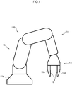
- the robot 10 is for example an industrial robot that performs various operations while gripping a workpiece, serving as a target object.
- An example of an operation performed by the robot 10 is an operation to assemble a finished product or a semi-finished product. More specifically, examples include an operation to insert an electronic component with a fragile terminal at a predetermined position, and an operation to fit together components that requires a large pressing force.
- the robot 10 includes a robot body 11 and a robotic hand 13.
- the robot body 11 includes a support 11a, and a robotic arm 11b attached to one end side of the support 11a.
- the robotic hand 13 is provided at another end side of the robotic arm 11b.
- the robotic hand 13 includes fingers 13a, 13b, each serving as an opposing section with respect to a tactile sensor (corresponding to a tactile sensor 100 or 200 explained with reference to Fig. 2 onward), described later.
- the tactile sensors are provided to mutually opposing surfaces S of the fingers 13a, 13b.
- the fingers 13a, 13b serving as opposing sections of the robotic hand 13 are driven toward a target object, such that the target object is gripped between the respective opposing sections and the corresponding tactile sensors.
- the above explanation is an example of a configuration of the robot 10 according to the present exemplary embodiment.
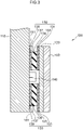
- Fig. 3 is a cross-section view sectioned along A-Ain Fig. 4 .
- the tactile sensor 100 is a device for qualitatively or quantitatively detecting force (load) acting on a cover 120 in a direction toward a base 110.
- the tactile sensor 100 detects force acting on the cover 120 from a target object that is being gripped between the tactile sensor 100 and the finger 13b serving as the opposing section thereto.
- the tactile sensor 100 includes the cover 120, a first force detection section 130, and a second force detection section 140.
- the base 110 is a plate shaped member that supports the tactile sensor 100.
- the base 110 may configure a portion of the fingers 13a, 13b of the robotic hand 13.
- a metal or a hard resin may be employed as the material of the base 110.
- the cover 120 is provided so as to cover at least part of the base 110.
- the cover 120 covers a range of the tactile sensor 100 required in order to detect force.
- the cover 120 covers a position corresponding to the finger 13a or 13b serving as the opposing section.
- the cover 120 is provided at a position opposing the base 110.
- the cover 120 is retained so as to be capable of moving in a direction toward the base 110.
- the material and shape of the cover 120 there is no particular limitation to the material and shape of the cover 120, as long as the cover 120 has sufficient rigidity with respect to force acting thereon, as described later.
- a metal or a hard resin may be employed as the material of the cover 120.
- the shape of the cover 120 is not limited to a rectangular shape such as that described later, and may be any desired shape that is capable of covering at least a portion of the base 110.
- the first force detection section 130 is provided between the cover 120 and the base 110, and detects force acting on the cover 120 in a direction toward the base 110 from the cover 120.
- the first force detection section 130 has a high detection sensitivity with respect to a relatively small force.
- the rating of load detected by the first force detection section 130 is a relatively small value.
- the first force detection section 130 detects force in a range from approximately 0.5N to approximately 20N.
- the detection sensitivity of the first force detection section 130 is approximately 0.5N.
- the first force detection section 130 has a configuration in which an elastic member is provided between a pair of substrates, and at least one of the substrates is provided with an electrode.
- the first force detection section 130 detects force acting on the cover 120 by detecting a change in electrical characteristics (such as a change in electrostatic capacitance or a change in a resistance value) between the pair of substrates, at least one of which is provided with an electrode, accompanying expansion or contraction of the elastic member.
- an electrode may be provided to each substrate of the pair of substrates.
- the first force detection section 130 is capable of detecting a relatively small force with a high sensitivity due to having the configuration in which the elastic member is provided between the pair of substrates, at least one of which is provided with an electrode.
- the first force detection section 130 has a configuration employing the elastic member that is capable of minute displacement, and so the first force detection section 130 is capable of detecting a small force with a high sensitivity.
- the first force detection section 130 is able to detect force acting on the cover 120 over a wide region of the cover 120, such that the ease of design of the tactile sensor 100 is improved.
- the first force detection section 130 may include an elastic member 139 between a first substrate 131 provided with a first electrode 133, and a second substrate 135 provided with a second electrode 137.
- the first force detection section 130 detects force acting on the cover 120 by detecting a change in electrostatic capacitance between the first electrode 133 and the second electrode 137 accompanying expansion or contraction of the elastic member 139.
- the first electrode 133 and the second electrode 137 are metal electrodes that oppose each other on either side of the elastic member 139.
- the first substrate 131 is a resin substrate provided with the first electrode 133 on a face opposing the second substrate 135.
- the second substrate 135 is a resin substrate provided with the second electrode 137 on a face opposing the first substrate 131.
- the elastic member 139 is a member having a predetermined elasticity such that the cover 120 displaces in a direction toward the base 110 when force acts on the cover 120.
- the elastic member 139 is provided between the first electrode 133 and the second electrode 137.
- the elastic member 139 is for example configured of a soft resin such as rubber.
- the material and structure of the elastic member 139 there is no particular limitation to the material and structure of the elastic member 139 as long as the elastic member 139 has a predetermined elasticity and is capable of changing a distance between the first electrode 133 and the second electrode 137 in response to force acting on the cover 120.
- the elastic member 139 may be configured of a leaf spring or a coil spring made of a resin or a metal.
- the elastic member 139 may be directly attached to the cover 120 and the base 110 so as to be capable of contacting and separating from the first electrode 133 and the second electrode 137.
- the first force detection section 130 may have a configuration in which the elastic member 139 is provided outside the electrodes, and is supported so as to be capable of contacting and separating from the first electrode 133 and the second electrode 137.
- the first substrate 131 provided with the first electrode 133 is provided across substantially the entire face on the base 110-side of the cover 120.
- the elastic member 139 and the second substrate 135 provided with the second electrode 137 are provided at a central portion between the base 110 and the cover 120 when the cover 120 is viewed in plan view. Namely, a region where the elastic member 139 and the second substrate 135 provided with the second electrode 137 are not provided is present at an outer peripheral side between the base 110 and the cover 120 when the cover 120 is viewed in plan view.
- the first force detection section 130 is provided in a region with a predetermined width between the cover 120 and the base 110. This enables force acting on the cover 120 to be detected over a wide region of the cover 120.
- a rectangular space may be provided in the first force detection section 130 at substantially the center of the elastic member 139 and of the pair of substrates provided with the electrodes.
- the second force detection section 140 is housed inside this space.
- the second force detection section 140 detects force acting on the cover 120 in cases in which the cover 120 is further displaced in a direction toward the base 110 after the first force detection section 130 has detected force acting on the cover 120.
- the second force detection section 140 is capable of detecting up to a relatively large force (namely load) over a wide range. Namely, a rating of load detected by the second force detection section 140 is a relatively high value.
- a maximum value of force that the second force detection section 140 is capable of detecting is larger than a maximum value of force that the first force detection section 130 is capable of detecting.
- the second force detection section 140 is capable of detecting force in a range from approximately 1.5N to approximately 50N.
- the detection sensitivity of the second force detection section 140 is approximately 1.5N.
- the tactile sensor 100 Since the maximum value of force that the second force detection section 140 is capable of detecting is larger than the maximum value of force that the first force detection section 130 is capable of detecting, a range in which force can be detected can be widened compared to cases in which force is only detected by the first force detection section 130. Furthermore, the second force detection section 140 detects force acting on the cover 120 in cases in which the cover 120 is further displaced in a direction toward the base 110 after the first force detection section 130 has detected force. Thus, a small force is detected with a high sensitivity by the first force detection section 130, and force is then detected by the second force detection section 140 in a range in with the first force detection section 130 has a low detection precision or cannot detect the force. Thus, the tactile sensor 100 according to the present exemplary embodiment enables a small force to be detected with a high sensitivity, and also enables the range in which force can be detected to be widened.
- the second force detection section 140 may be a single axial direction force sensor that detects force in a direction from the cover 120 toward the base 110. Employing a force sensor capable of detecting up to a relatively large force enables force to be detected over a wider range than in cases in which only the first force detection section 130 is provided.
- the second force detection section 140 may for example be a piezoresistive force sensor.
- the force sensor serving as the second force detection section 140 has a structure with a higher rigidity (namely, is less likely to be displaced) than the first force detection section 130 with the configuration including the elastic member 139. Namely, the second force detection section 140 is capable of detecting a relatively large force with a small stroke. This suppresses the first force detection section 130 from deforming excessively under a large stroke due to a relatively large force being detected by the second force detection section 140. Moreover, the output from the second force detection section 140 with respect to a relatively large force acting on the cover 120 is a linear response, thereby facilitating control employing output from the tactile sensor 100.
- the second force detection section 140 is disposed inside the rectangular space provided at the substantially central portion of the first force detection section 130.
- the second force detection section 140 is attached to the base 110 inside this space.
- the second force detection section 140 is configured so as not to contact the face on the base 110-side of the cover 120 in a state in which force is not acting on the cover 120, and in a state in which displacement of the cover 120 in a direction toward the base 110 is small.
- the cover 120 and the single axial direction force sensor serving as the second force detection section 140 contact one another.
- the force acting on the cover 120 is detected by the second force detection section 140 as a result.
- a protrusion that projects toward the single axial direction force sensor serving as the second force detection section 140 may be provided to the cover 120 at a position corresponding to the force sensor in order to facilitate detection of force acting on the cover 120.
- the second force detection section 140 may include plural force sensors in order to realize the force detection range described previously. In such cases, the second force detection section 140 does not have to be provided at the substantially central portion of the first force detection section 130. Namely, the plural force sensors serving as the second force detection section 140 may be provided at discrete positions between the cover 120 and the base 110.
- the tactile sensor 100 may also include a restricting structure 150.
- the restricting structure 150 restricts tilting of the cover 120 with respect to the base 110. Restricting tilting of the cover 120 with respect to the base 110 using the restricting structure 150 enables disproportionate detection of force at a specific location to be prevented. As a result, force occurring in the cover 120 is precisely detected by the first force detection section 130 or the second force detection section 140 of the tactile sensor 100, enabling the range in which force can be detected by the tactile sensor 100 to be widened.
- the restricting structure 150 may be configured of stoppers 151 that restrict movement of the cover 120 in a direction toward the base 110.
- the stoppers 151 are substantially rectangular block shaped members that are fixed to the base 110.
- End faces on the opposite side of the stoppers 151 to the base 110 are capable of directly or indirectly abutting the face on the base 110-side of the cover 120.
- a gap of a predetermined distance is provided between the end faces on the opposite side of the stoppers 151 to the base 110 and the face on the base 110-side of the cover 120.
- the cover 120 is displaced in a direction toward the base when force acts on the cover 120.
- the stoppers 151 are provided at positions corresponding to peripheral edges of the cover 120. This restricts the peripheral edges of the cover 120 from moving in a direction toward the base 110, such that tilting of the cover 120 is suppressed. Moreover, the stoppers 151 are provided at positions corresponding to the four corners of the rectangular cover 120. This restricts the four corners of the cover 120 from moving in a direction toward the base 110, such that tilting of the cover 120 is suppressed. As a result, force occurring in the cover 120 is precisely detected by the first force detection section 130 or the second force detection section 140 of the tactile sensor 100, enabling the range in which force can be detected by the tactile sensor 100 to be widened.
- the material and shape of the stoppers 151 there is no particular limitation to the material and shape of the stoppers 151, as long as the stoppers 151 have a predetermined rigidity so as to be capable of supporting the cover 120.
- the rigidity of the stoppers 151 should be no less than the rigidity of the elastic member 139.
- a metal or a hard resin may be employed as the material of the stoppers 151.
- the tactile sensor 100 may also include a contact section 160.
- the contact section 160 is provided to a face on the opposite side of the cover 120 to the base 110, and contacts a target location.
- the contact section 160 can be exchanged for another contact section 160 by being removed from the cover.
- Direct contact between the target location and the cover is avoided as a result of including the contact section 160, such that the target location and the cover are protected.
- configuring the contact section 160 as exchangeable enables the contact section 160 to be replaced when worn. This suppresses a biased distribution of force from acting on the cover 120 due to the contact section 160 deteriorating and becoming misshapen.
- force acting on the cover 120 is precisely detected by the first force detection section 130 or the second force detection section 140, enabling the range in which force can be detected by the tactile sensor 100 to be widened.
- a contact section 160 with suitable characteristics or shape can be employed depending on the type of workpiece or the content of the operation to be performed by the robotic hand 13.
- a contact section 160 configured from a material with a high friction coefficient may be employed.
- a contact section 160 with a profile including a spherical surface corresponding to the workpiece may be employed. The ease of manipulation using the robotic hand 13 is improved as a result.
- An example of a schematic configuration of the tactile sensor 100 according to the present exemplary embodiment has been explained above.
- a relatively small force F1 may act on the cover 120 as illustrated in Fig. 5 .
- the elastic member 139 undergoes compression deformation in the direction of the force F1 in response to the magnitude of the force F1.
- the distance between the first electrode 133 and the second electrode 137 changes, and the electrical characteristics of the elastic member 139, such as electrostatic capacitance, change as a result.
- the first force detection section 130 detects the force F1 with a high sensitivity based on this change in electrical characteristics.
- the force F1 is relatively small, a compression amount of the elastic member 139 (namely, a displacement amount of the cover 120 toward the base 110) is small, and the force is either not detected or barely detected by the second force detection section 140.
- the tactile sensor 100 performs output relating to the detected force F1.
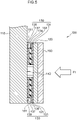
- a relatively large force F2 may act on the cover 120 as illustrated in Fig. 6 .
- the elastic member 139 of the first force detection section 130 is compressed in the direction of the force F2, and the first force detection section 130 detects the force F2 as described above. If the force F2 is sufficiently large, after the first force detection section 130 has started to detect the force F2, the cover 120 is further displaced in a direction toward the base 110. The cover 120 contacts the second force detection section 140 as a result, and the second force detection section 140 detects the force F2 acting on the cover 120.
- the tactile sensor 100 performs output relating to the detected force F2.
- the first force detection section 130 is configured so as to be capable of detecting a relatively small force with a high sensitivity.
- the second force detection section 140 is capable of detecting a relatively large force.
- a relatively large force such as the force F2 illustrated in Fig. 6 acts on the cover 120
- the force is detected by the second force detection section 140 after the first force detection section 130 has detected the force, thereby enabling the relatively large force to be detected. Examples of operation of the tactile sensor 100 according to the present exemplary embodiment have been explained above.
- the tactile sensor 100 includes the second force detection section 140 that detects force acting on the cover 120 in cases in which the cover 120 is further displaced in a direction toward the base 110 after the first force detection section 130 has detected force acting on the cover 120.
- This enables a relatively small force to be detected with a high sensitivity by the first force detection section 130, and up to a relatively large force to be detected by the second force detection section 140.
- This enables a small force to be detected with a high sensitivity and the range in which force can be detected to be widened compared to cases in which forces are detected by the same type of force detection section.
- the robotic hand 13 or the robot 10 including the tactile sensor 100 according to the present exemplary embodiment enables a small force to be detected with a high sensitivity and the range in which force can be detected to be widened, thereby enabling various operations, such a delicate operation requiring a small force and a fitting operation requiring a large force, to be handled.
- the robotic hand 13 or the robot 10 according to the present exemplary embodiment can handle various workpieces and operations using such workpieces with versatility.
- An example of an exemplary embodiment of the tactile sensor 100 according to the present disclosure has been described above.
- the present modified example differs to the above exemplary embodiment in the respect that the method by which the first force detection section 130 detects force acting on the cover 120 is a method in which a change in electrical resistance of the elastic member 139 is detected.
- Other configuration of the present modified example is the same as in the above exemplary embodiment, and so explanation thereof is omitted.
- the elastic member 139 has a predetermined conductivity.
- the elastic member 139 may be a rubber member containing conductive particles (such as metal particles) dispersed therein.
- a resistance value of the elastic member 139 changes when the conductive elastic member 139 expands or contracts. This change in the resistance value is detected by measuring electrical resistance between the first electrode 133 and the second electrode 137.
- a circuit may be formed by connecting a lead wire to the elastic member 139, and electrical resistance measured as the change in the resistance value of the elastic member 139.
- a configuration may be applied in which two electrodes for measuring the resistance value are provided to either one out of the pair of substrates.
- the elastic member 139 of the first force detection section 130 is conductive, and the change in the resistance value due to expansion or contraction of the elastic member 139 is detected in order to detect force acting on the cover 120. This enables a relatively small force that can be detected using the first force detection section 130 to be precisely detected using a relatively simple configuration.
- a modified example of the tactile sensor 100 according to the present exemplary embodiment has been explained above.
- a tactile sensor 200 according to the present exemplary embodiment differs to the first exemplary embodiment in the respect that mechanisms for detecting force are provided at plural locations. Note that explanation of common points to the configuration of the first exemplary embodiment is sometimes omitted from the explanation of the present exemplary embodiment.
- the tactile sensor 200 is configured including a base 110, first force detection sections 130, second force detection sections 140, and a cover 220.
- the cover 220 is a plate shaped member with a substantially L-shaped profile in cross-section view.
- the cover 220 includes a side face covering portion 221 and an end face covering portion 223.
- the side face covering portion 221 is a location disposed along a side face 111 of the base 110 at the inside of the cover 220.
- the end face covering portion 223 extends out from an end portion of the side face covering portion 221 in a direction extending along the base 110, and is a location disposed along an end face 113 of the base 110.
- a first force detection section 130 and a second force detection section 140 are provided between the side face covering portion 221 of the cover 220 and the side face 111 of the base 110.
- a first force detection section 130 and a second force detection section 140 are also provided between the end face covering portion 223 of the cover 220 and the end face 113 of the base 110.
- the tactile sensor 200 also includes stoppers 250.
- the stoppers 250 includes a side face stopper 251 and an end face stopper 253.
- the side face stopper 251 is a member with an L-shaped cross-section profile that is provided to the side face 111 of the base 110.
- the side face stopper 251 includes a first contact portion 251a configuring one location of the L shape, and a second contact portion 251b configuring another location of the L shape that bends away from the one location.
- the first contact portion 251a is a location extending along the side face 111, and the side face stopper 251 is attached to the base 110 through the first contact portion 251a.
- the first contact portion 251a is capable of abutting a base 110-side face of the side face covering portion 221 of the cover 220. On contacting the side face covering portion 221, the first contact portion 251a restricts the side face covering portion 221 from moving in a direction toward the side face 111 of the base 110.
- the second contact portion 251b is a location protruding out along a normal direction to the side face 111 from the first contact portion 251a.
- the second contact portion 251b is capable of abutting one end face 221a of the side face covering portion 221.
- the second contact portion 251b restricts the end face covering portion 223 from moving in a direction toward the end face 113 of the base 110.
- the end face stopper 253 is a member with an L-shaped cross-section profile that is provided to the end face 113 of the base 110.
- the end face stopper 253 includes a third contact portion 253a configuring one location of the L shape, and a fourth contact portion 253b configuring another location of the L shape that bends away from the one location.
- the third contact portion 253a is a location protruding out along a normal direction to the end face 113.
- the third contact portion 253a is capable of abutting another end face 223a of the end face covering portion 223.
- the third contact portion 253a restricts the side face covering portion 221 from moving in a direction toward the side face 111 of the base 110.
- the fourth contact portion 253b is a location extending along the end face 113 from the third contact portion 253a, and the end face stopper 253 is attached to the base 110 through the fourth contact portion 253b.
- the fourth contact portion 253b is capable of abutting a base 110-side face of the end face covering portion 223 of the cover 220. On contacting the end face covering portion 223, the fourth contact portion 253b restricts the end face covering portion 223 from moving in a direction toward the end face 113 of the base 110.
- a force F3 may act on the side face covering portion 221 of the cover 220.
- the cover 220 is displaced in a direction toward the side face 111 of the base 110.
- the force F3 is detected by the first force detection section 130 and the second force detection section 140 provided between the side face covering portion 221 and the side face 111 of the base 110. If the force F3 is sufficiently large, the cover 220 is further displaced in a direction toward the base 110.
- the side face covering portion 221 of the cover 220 abuts the first contact portion 251a of the side face stopper 251 as a result.
- the other end face 223a of the end face covering portion 223 of the cover 220 abuts the third contact portion 253a of the end face stopper 253.
- detection of the force in a state in which the side face covering portion 221 is tilted with respect to the side face 111 of the base 110 is suppressed by the first contact portion 251a of the side face stopper 251 and the third contact portion 253a of the end face stopper 253.
- a force F4 may act on the end face covering portion 223 of the cover 220.
- the cover 220 is displaced in a direction toward the end face 113 of the base 110.
- the force F4 is detected by the first force detection section 130 and the second force detection section 140 provided between the end face covering portion 223 and the end face 113 of the base 110. If the force F4 is sufficiently large, the cover 220 is further displaced in a direction toward the base 110.
- the end face covering portion 223 of the cover 220 abuts the fourth contact portion 253b of the end face stopper 253 as a result.
- the one end face 221a of the side face covering portion 221 of the cover 220 abuts the second contact portion 251b of the side face stopper 251.
- detection of the force in a state in which the end face covering portion 223 is tilted with respect to the end face 113 of the base 110 is suppressed by the second contact portion 251b of the side face stopper 251 and the fourth contact portion 253b of the end face stopper 253.
- the cover 220 includes the side face covering portion 221 and the end face covering portion 223. This enables not only detection of force directed toward the side face 111 of the base 110 from the side face covering portion 221 of the cover 220, but also detection of force directed toward the end face 113 of the base 110 from the end face covering portion 223 of the cover 220. Furthermore, in the tactile sensor 200 according to the present exemplary embodiment, the base 110 is provided with the side face stopper 251 and the end face stopper 253 that restrict movement of the cover 220 in respective directions toward the side face 111 and the end face 113 of the base 110.
- Including the tactile sensor 200 in the robot 10 and the robotic hand 13 enables not only detection of force acting on the surfaces S for gripping a workpiece, but also detection of force acting on lower faces of the fingers 13a, 13b. This enables detection of states relating to various operations, not only when a workpiece is being gripped, but also when a workpiece is being inserted using the fingertips.
- Another example of an exemplary embodiment of the tactile sensor 200 according to the present disclosure has been described above.
- the configuration of the first force detection section 130 has been described as a configuration in which a change in electrostatic capacitance or a resistance value accompanying expansion or contraction of the elastic member 139 is detected in the above exemplary embodiments, the present disclosure is not restricted to this example.
- a configuration in which a stacked body configured of a piezoelectric material and the elastic member 139 is sandwiched between a pair of electrodes, and a variation in load (change in permittivity) is detected by distortion occurring in the piezoelectric material may be applied as the configuration of the first force detection section 130.
- a configuration in which magnetic particles are dispersed inside the elastic member 139, and a change in reactance accompanying expansion or contraction of the elastic member 139 is detected may be applied as another configuration of the first force detection section 130.
- a configuration in which a change in resonance frequency accompanying expansion or contraction of the elastic member 139 is detected may be applied as another configuration of the first force detection section 130.
- the stoppers 151 may be provided to the base 110-side face of the cover 120.
- a tactile sensor 100 or 200 may be provided to only one out of the fingers 13a, 13b of the robotic hand 13.
- the tactile sensor 100 or 200 may be provided to a location other than the fingers 13a, 13b of the robotic hand 13.
- the tactile sensor 100 or 200 may be provided to a wrist portion that is a coupling location between the robotic hand 13 and the other end side of the robotic arm 11b.
- the tactile sensor 100 or 200 may be provided at any desired position of the robot body 11, including the robotic arm 11b. This enables contact between an operator and the robot 10 to be detected.
- the tactile sensor 100 or 200 is applied to a robot 10 serving as an industrial robot in the above exemplary embodiments, application is not limited to an industrial robot.
- the tactile sensor 100 or 200 may be applied to various service robots, pet robots, or humanoid robots serving as non-industrial robots.
- the present disclosure includes the following aspects.
Landscapes
- Engineering & Computer Science (AREA)
- Human Computer Interaction (AREA)
- Robotics (AREA)
- Mechanical Engineering (AREA)
- Manipulator (AREA)
- Force Measurement Appropriate To Specific Purposes (AREA)
Abstract
Description
- The present disclosure relates to a tactile sensor, a robotic hand, and a robot.
- Various technology relating to a tactile sensor provided to a robotic hand has been proposed with respect to cases in which an object such as a workpiece is gripped by the robotic hand, and the object is then transported or assembled to another object that is an assembly target.
- For example, technology has been proposed in which electrostatic capacitance pressure sensors collectively serving as a 6-axis force sensor are disposed and fixed at twelve locations on an outer face of an internal support body so as to enable detection of pressing force from above, below, left, right, front, and rear (Japanese Patent Application Laid-Open (
JP-A) No. 2016-205942 - The technology disclosed in
JP-ANo. 2016-205942 - In consideration of the above points, an object of the present disclosure is to provide a tactile sensor, a robotic hand, and a robot that are capable of detecting a small force with a high sensitivity and are also capable of widening a range in which force can detected compared to cases in which force is detected by the same type of force detection section. Solution to Problem
- In order to achieve the above object, a tactile sensor according to the present disclosure includes a cover provided so as to cover at least a portion of a base, a first force detection section configured to detect a force acting on the cover in a direction toward the base from the cover, and a second force detection section configured to detect the force acting on the cover in a case in which the cover is further displaced in the direction toward the base after the first force detection section has detected the force acting on the cover. Advantageous Effects of Invention
- The tactile sensor, the robotic hand, and the robot according to the present disclosure include the first force detection section configured to detect force acting on the cover and the second force detection section configured to detect force acting on the cover in cases in which the cover is further displaced in a direction toward the base after the first force detection section has detected force acting on the cover. This enables a small force to be detected with a high sensitivity and the range in which force can be detected to be widened compared to cases in which forces are detected by the same type of force detection section.
-
-
Fig. 1 is a schematic view illustrating an example of a configuration of a robot according to a first exemplary embodiment of the present disclosure. -
Fig. 2 is an exploded perspective view illustrating an example of a configuration of a tactile sensor according to the first exemplary embodiment. -
Fig. 3 is a cross-section illustrating an example of a configuration of a tactile sensor according to the first exemplary embodiment. -
Fig. 4 is a plan view illustrating an example of a configuration of a tactile sensor according to the first exemplary embodiment. -
Fig. 5 is a cross-section illustrating an example of a scenario when force has been applied to a tactile sensor according to the first exemplary embodiment. -
Fig. 6 is a cross-section illustrating an example of a scenario when force has acted on a tactile sensor according to the first exemplary embodiment. -
Fig. 7 is a cross-section illustrating an example of a configuration of a tactile sensor according to a second exemplary embodiment of the present disclosure. - Explanation follows regarding examples of exemplary embodiments of the present disclosure, with reference to the drawings. Note that in the respective drawings, the same or equivalent configuration elements and sections are allocated the same reference numerals. Moreover, the dimensional proportions in the drawings may be exaggerated to aid explanation, and may therefore differ from actual proportions.
- First, explanation follows regarding an example of a schematic configuration of a
robot 10 according to an exemplary embodiment, with reference toFig. 1 . Therobot 10 according to the present exemplary embodiment is for example an industrial robot that performs various operations while gripping a workpiece, serving as a target object. An example of an operation performed by therobot 10 is an operation to assemble a finished product or a semi-finished product. More specifically, examples include an operation to insert an electronic component with a fragile terminal at a predetermined position, and an operation to fit together components that requires a large pressing force. As illustrated inFig. 1 , therobot 10 includes arobot body 11 and arobotic hand 13. - The
robot body 11 includes asupport 11a, and arobotic arm 11b attached to one end side of thesupport 11a. Therobotic hand 13 is provided at another end side of therobotic arm 11b. Therobotic hand 13 includesfingers tactile sensor Fig. 2 onward), described later. The tactile sensors are provided to mutually opposing surfaces S of thefingers fingers robotic hand 13 are driven toward a target object, such that the target object is gripped between the respective opposing sections and the corresponding tactile sensors. The above explanation is an example of a configuration of therobot 10 according to the present exemplary embodiment. - Next, explanation follows regarding an example of a schematic configuration of a
tactile sensor 100 according to the present exemplary embodiment, with reference toFig. 2 ,Fig. 3 , andFig. 4 .Fig. 3 is a cross-section view sectioned along A-AinFig. 4 . Thetactile sensor 100 is a device for qualitatively or quantitatively detecting force (load) acting on acover 120 in a direction toward abase 110. In cases in which thetactile sensor 100 is applied to thefinger 13a of therobotic hand 13, thetactile sensor 100 detects force acting on thecover 120 from a target object that is being gripped between thetactile sensor 100 and thefinger 13b serving as the opposing section thereto. As illustrated inFig. 2 , thetactile sensor 100 includes thecover 120, a firstforce detection section 130, and a secondforce detection section 140. - The
base 110 is a plate shaped member that supports thetactile sensor 100. Thebase 110 may configure a portion of thefingers robotic hand 13. There is no particular restriction to the material and shape of thebase 110, as long as at least a portion of thebase 110 can be covered by thecover 120, described below. For example, a metal or a hard resin may be employed as the material of thebase 110. - The
cover 120 is provided so as to cover at least part of thebase 110. In particular, thecover 120 covers a range of thetactile sensor 100 required in order to detect force. In cases in which thetactile sensor 100 is employed in therobotic hand 13, thecover 120 covers a position corresponding to thefinger Fig. 3 , thecover 120 is provided at a position opposing thebase 110. Thecover 120 is retained so as to be capable of moving in a direction toward thebase 110. There is no particular limitation to the material and shape of thecover 120, as long as thecover 120 has sufficient rigidity with respect to force acting thereon, as described later. For example, a metal or a hard resin may be employed as the material of thecover 120. Moreover, the shape of thecover 120 is not limited to a rectangular shape such as that described later, and may be any desired shape that is capable of covering at least a portion of thebase 110. - The first
force detection section 130 is provided between thecover 120 and thebase 110, and detects force acting on thecover 120 in a direction toward thebase 110 from thecover 120. The firstforce detection section 130 has a high detection sensitivity with respect to a relatively small force. The rating of load detected by the firstforce detection section 130 is a relatively small value. Specifically, the firstforce detection section 130 detects force in a range from approximately 0.5N to approximately 20N. In particular, the detection sensitivity of the firstforce detection section 130 is approximately 0.5N. - The first
force detection section 130 has a configuration in which an elastic member is provided between a pair of substrates, and at least one of the substrates is provided with an electrode. The firstforce detection section 130 detects force acting on thecover 120 by detecting a change in electrical characteristics (such as a change in electrostatic capacitance or a change in a resistance value) between the pair of substrates, at least one of which is provided with an electrode, accompanying expansion or contraction of the elastic member. Note that an electrode may be provided to each substrate of the pair of substrates. - The first
force detection section 130 is capable of detecting a relatively small force with a high sensitivity due to having the configuration in which the elastic member is provided between the pair of substrates, at least one of which is provided with an electrode. Namely, the firstforce detection section 130 has a configuration employing the elastic member that is capable of minute displacement, and so the firstforce detection section 130 is capable of detecting a small force with a high sensitivity. Moreover, due to having the configuration in which the elastic member is provided between the pair of substrates, at least one of which is provided with an electrode, the firstforce detection section 130 is able to detect force acting on thecover 120 over a wide region of thecover 120, such that the ease of design of thetactile sensor 100 is improved. - Specifically, as illustrated in
Fig. 3 , the firstforce detection section 130 may include anelastic member 139 between afirst substrate 131 provided with afirst electrode 133, and asecond substrate 135 provided with asecond electrode 137. The firstforce detection section 130 detects force acting on thecover 120 by detecting a change in electrostatic capacitance between thefirst electrode 133 and thesecond electrode 137 accompanying expansion or contraction of theelastic member 139. - The
first electrode 133 and thesecond electrode 137 are metal electrodes that oppose each other on either side of theelastic member 139. Thefirst substrate 131 is a resin substrate provided with thefirst electrode 133 on a face opposing thesecond substrate 135. Thesecond substrate 135 is a resin substrate provided with thesecond electrode 137 on a face opposing thefirst substrate 131. - The
elastic member 139 is a member having a predetermined elasticity such that thecover 120 displaces in a direction toward the base 110 when force acts on thecover 120. - The
elastic member 139 is provided between thefirst electrode 133 and thesecond electrode 137. Theelastic member 139 is for example configured of a soft resin such as rubber. There is no particular limitation to the material and structure of theelastic member 139 as long as theelastic member 139 has a predetermined elasticity and is capable of changing a distance between thefirst electrode 133 and thesecond electrode 137 in response to force acting on thecover 120. For example, theelastic member 139 may be configured of a leaf spring or a coil spring made of a resin or a metal. Theelastic member 139 may be directly attached to thecover 120 and the base 110 so as to be capable of contacting and separating from thefirst electrode 133 and thesecond electrode 137. Instead of theelastic member 139 being provided between the electrodes, the firstforce detection section 130 according to the present exemplary embodiment may have a configuration in which theelastic member 139 is provided outside the electrodes, and is supported so as to be capable of contacting and separating from thefirst electrode 133 and thesecond electrode 137. - As illustrated in
Fig. 4 , thefirst substrate 131 provided with thefirst electrode 133 is provided across substantially the entire face on the base 110-side of thecover 120. On the other hand, theelastic member 139 and thesecond substrate 135 provided with thesecond electrode 137 are provided at a central portion between the base 110 and thecover 120 when thecover 120 is viewed in plan view. Namely, a region where theelastic member 139 and thesecond substrate 135 provided with thesecond electrode 137 are not provided is present at an outer peripheral side between the base 110 and thecover 120 when thecover 120 is viewed in plan view. In this manner, the firstforce detection section 130 is provided in a region with a predetermined width between thecover 120 and thebase 110. This enables force acting on thecover 120 to be detected over a wide region of thecover 120. - As illustrated in
Fig. 2 , a rectangular space may be provided in the firstforce detection section 130 at substantially the center of theelastic member 139 and of the pair of substrates provided with the electrodes. The secondforce detection section 140, described below, is housed inside this space. - The second
force detection section 140 detects force acting on thecover 120 in cases in which thecover 120 is further displaced in a direction toward the base 110 after the firstforce detection section 130 has detected force acting on thecover 120. The secondforce detection section 140 is capable of detecting up to a relatively large force (namely load) over a wide range. Namely, a rating of load detected by the secondforce detection section 140 is a relatively high value. - In particular, a maximum value of force that the second
force detection section 140 is capable of detecting is larger than a maximum value of force that the firstforce detection section 130 is capable of detecting. Specifically, the secondforce detection section 140 is capable of detecting force in a range from approximately 1.5N to approximately 50N. The detection sensitivity of the secondforce detection section 140 is approximately 1.5N. - Since the maximum value of force that the second
force detection section 140 is capable of detecting is larger than the maximum value of force that the firstforce detection section 130 is capable of detecting, a range in which force can be detected can be widened compared to cases in which force is only detected by the firstforce detection section 130. Furthermore, the secondforce detection section 140 detects force acting on thecover 120 in cases in which thecover 120 is further displaced in a direction toward the base 110 after the firstforce detection section 130 has detected force. Thus, a small force is detected with a high sensitivity by the firstforce detection section 130, and force is then detected by the secondforce detection section 140 in a range in with the firstforce detection section 130 has a low detection precision or cannot detect the force. Thus, thetactile sensor 100 according to the present exemplary embodiment enables a small force to be detected with a high sensitivity, and also enables the range in which force can be detected to be widened. - The second
force detection section 140 may be a single axial direction force sensor that detects force in a direction from thecover 120 toward thebase 110. Employing a force sensor capable of detecting up to a relatively large force enables force to be detected over a wider range than in cases in which only the firstforce detection section 130 is provided. The secondforce detection section 140 may for example be a piezoresistive force sensor. - The force sensor serving as the second
force detection section 140 has a structure with a higher rigidity (namely, is less likely to be displaced) than the firstforce detection section 130 with the configuration including theelastic member 139. Namely, the secondforce detection section 140 is capable of detecting a relatively large force with a small stroke. This suppresses the firstforce detection section 130 from deforming excessively under a large stroke due to a relatively large force being detected by the secondforce detection section 140. Moreover, the output from the secondforce detection section 140 with respect to a relatively large force acting on thecover 120 is a linear response, thereby facilitating control employing output from thetactile sensor 100. In particular, in cases in which the firstforce detection section 130 is configured including theelastic member 139, output from the firstforce detection section 130 with respect to a relatively large force is non-linear. Thus, utilizing the linear response from the secondforce detection section 140 in cases in which a relatively large force is detected further facilitates control. - As illustrated in
Fig. 3 andFig. 4 , the secondforce detection section 140 is disposed inside the rectangular space provided at the substantially central portion of the firstforce detection section 130. The secondforce detection section 140 is attached to thebase 110 inside this space. The secondforce detection section 140 is configured so as not to contact the face on the base 110-side of thecover 120 in a state in which force is not acting on thecover 120, and in a state in which displacement of thecover 120 in a direction toward thebase 110 is small. - In cases in which force is acting on the
cover 120 and thecover 120 is displaced in a direction toward the base 110 by a predetermined distance or greater, thecover 120 and the single axial direction force sensor serving as the secondforce detection section 140 contact one another. The force acting on thecover 120 is detected by the secondforce detection section 140 as a result. A protrusion that projects toward the single axial direction force sensor serving as the secondforce detection section 140 may be provided to thecover 120 at a position corresponding to the force sensor in order to facilitate detection of force acting on thecover 120. - Moreover, the second
force detection section 140 may include plural force sensors in order to realize the force detection range described previously. In such cases, the secondforce detection section 140 does not have to be provided at the substantially central portion of the firstforce detection section 130. Namely, the plural force sensors serving as the secondforce detection section 140 may be provided at discrete positions between thecover 120 and thebase 110. - The
tactile sensor 100 according to the present exemplary embodiment may also include a restrictingstructure 150. The restrictingstructure 150 restricts tilting of thecover 120 with respect to thebase 110. Restricting tilting of thecover 120 with respect to the base 110 using the restrictingstructure 150 enables disproportionate detection of force at a specific location to be prevented. As a result, force occurring in thecover 120 is precisely detected by the firstforce detection section 130 or the secondforce detection section 140 of thetactile sensor 100, enabling the range in which force can be detected by thetactile sensor 100 to be widened. - Specifically, the restricting
structure 150 may be configured ofstoppers 151 that restrict movement of thecover 120 in a direction toward thebase 110. Thestoppers 151 are substantially rectangular block shaped members that are fixed to thebase 110. - End faces on the opposite side of the
stoppers 151 to the base 110 are capable of directly or indirectly abutting the face on the base 110-side of thecover 120. As illustrated inFig. 3 , in a state in which force is not acting on thecover 120, a gap of a predetermined distance is provided between the end faces on the opposite side of thestoppers 151 to thebase 110 and the face on the base 110-side of thecover 120. Thecover 120 is displaced in a direction toward the base when force acts on thecover 120. When this occurs, in cases in which force only concentrates at a portion of thecover 120 such that that thecover 120 is displaced at a tilt with respect to thebase 110, thestoppers 151 support thecover 120 such that this tilting of thecover 120 is suppressed. - As illustrated in
Fig. 4 , thestoppers 151 are provided at positions corresponding to peripheral edges of thecover 120. This restricts the peripheral edges of thecover 120 from moving in a direction toward thebase 110, such that tilting of thecover 120 is suppressed. Moreover, thestoppers 151 are provided at positions corresponding to the four corners of therectangular cover 120. This restricts the four corners of thecover 120 from moving in a direction toward thebase 110, such that tilting of thecover 120 is suppressed. As a result, force occurring in thecover 120 is precisely detected by the firstforce detection section 130 or the secondforce detection section 140 of thetactile sensor 100, enabling the range in which force can be detected by thetactile sensor 100 to be widened. - There is no particular limitation to the material and shape of the
stoppers 151, as long as thestoppers 151 have a predetermined rigidity so as to be capable of supporting thecover 120. In particular, the rigidity of thestoppers 151 should be no less than the rigidity of theelastic member 139. For example, a metal or a hard resin may be employed as the material of thestoppers 151. - The
tactile sensor 100 according to the present exemplary embodiment may also include acontact section 160. Thecontact section 160 is provided to a face on the opposite side of thecover 120 to thebase 110, and contacts a target location. Thecontact section 160 can be exchanged for anothercontact section 160 by being removed from the cover. There is no particular limitation to the shape and material of thecontact section 160. - Direct contact between the target location and the cover is avoided as a result of including the
contact section 160, such that the target location and the cover are protected. Moreover, configuring thecontact section 160 as exchangeable enables thecontact section 160 to be replaced when worn. This suppresses a biased distribution of force from acting on thecover 120 due to thecontact section 160 deteriorating and becoming misshapen. Thus, force acting on thecover 120 is precisely detected by the firstforce detection section 130 or the secondforce detection section 140, enabling the range in which force can be detected by thetactile sensor 100 to be widened. Moreover, in cases in which thecontact section 160 has deteriorated, it is sufficient to exchange thecontact section 160 alone, such that the ease of maintenance is improved. - Moreover, by configuring the
contact section 160 as exchangeable, in cases in which thetactile sensor 100 is employed in therobotic hand 13, acontact section 160 with suitable characteristics or shape can be employed depending on the type of workpiece or the content of the operation to be performed by therobotic hand 13. For example, in cases in which the workpiece is smooth and slips easily, acontact section 160 configured from a material with a high friction coefficient may be employed. Alternatively, in cases in which the workpiece has an outer profile including a spherical surface, acontact section 160 with a profile including a spherical surface corresponding to the workpiece may be employed. The ease of manipulation using therobotic hand 13 is improved as a result. An example of a schematic configuration of thetactile sensor 100 according to the present exemplary embodiment has been explained above. - Next, explanation follows regarding examples of operation of the
tactile sensor 100 according to the present exemplary embodiment, with reference toFig. 5 andFig. 6 . As an example, a relatively small force F1 may act on thecover 120 as illustrated inFig. 5 . When this occurs, theelastic member 139 undergoes compression deformation in the direction of the force F1 in response to the magnitude of the force F1. The distance between thefirst electrode 133 and thesecond electrode 137 changes, and the electrical characteristics of theelastic member 139, such as electrostatic capacitance, change as a result. The firstforce detection section 130 detects the force F1 with a high sensitivity based on this change in electrical characteristics. When this occurs, since the force F1 is relatively small, a compression amount of the elastic member 139 (namely, a displacement amount of thecover 120 toward the base 110) is small, and the force is either not detected or barely detected by the secondforce detection section 140. Thetactile sensor 100 performs output relating to the detected force F1. - As another example, a relatively large force F2 may act on the
cover 120 as illustrated inFig. 6 . When this occurs, first, theelastic member 139 of the firstforce detection section 130 is compressed in the direction of the force F2, and the firstforce detection section 130 detects the force F2 as described above. If the force F2 is sufficiently large, after the firstforce detection section 130 has started to detect the force F2, thecover 120 is further displaced in a direction toward thebase 110. Thecover 120 contacts the secondforce detection section 140 as a result, and the secondforce detection section 140 detects the force F2 acting on thecover 120. Thetactile sensor 100 performs output relating to the detected force F2. - As described above, the first
force detection section 130 is configured so as to be capable of detecting a relatively small force with a high sensitivity. On the other hand, the secondforce detection section 140 is capable of detecting a relatively large force. Thus, in cases in which a relatively large force such as the force F2 illustrated inFig. 6 acts on thecover 120, the force is detected by the secondforce detection section 140 after the firstforce detection section 130 has detected the force, thereby enabling the relatively large force to be detected. Examples of operation of thetactile sensor 100 according to the present exemplary embodiment have been explained above. - The
tactile sensor 100 according to the present exemplary embodiment includes the secondforce detection section 140 that detects force acting on thecover 120 in cases in which thecover 120 is further displaced in a direction toward the base 110 after the firstforce detection section 130 has detected force acting on thecover 120. This enables a relatively small force to be detected with a high sensitivity by the firstforce detection section 130, and up to a relatively large force to be detected by the secondforce detection section 140. This enables a small force to be detected with a high sensitivity and the range in which force can be detected to be widened compared to cases in which forces are detected by the same type of force detection section. - Moreover, the
robotic hand 13 or therobot 10 including thetactile sensor 100 according to the present exemplary embodiment enables a small force to be detected with a high sensitivity and the range in which force can be detected to be widened, thereby enabling various operations, such a delicate operation requiring a small force and a fitting operation requiring a large force, to be handled. Namely, therobotic hand 13 or therobot 10 according to the present exemplary embodiment can handle various workpieces and operations using such workpieces with versatility. An example of an exemplary embodiment of thetactile sensor 100 according to the present disclosure has been described above. - Next, explanation follows regarding a modified example of the
tactile sensor 100 according to the present exemplary embodiment. The present modified example differs to the above exemplary embodiment in the respect that the method by which the firstforce detection section 130 detects force acting on thecover 120 is a method in which a change in electrical resistance of theelastic member 139 is detected. Other configuration of the present modified example is the same as in the above exemplary embodiment, and so explanation thereof is omitted. - In the present modified example, the
elastic member 139 has a predetermined conductivity. For example, theelastic member 139 may be a rubber member containing conductive particles (such as metal particles) dispersed therein. A resistance value of theelastic member 139 changes when the conductiveelastic member 139 expands or contracts. This change in the resistance value is detected by measuring electrical resistance between thefirst electrode 133 and thesecond electrode 137. Alternatively, rather than providing thefirst electrode 133 and thesecond electrode 137, a circuit may be formed by connecting a lead wire to theelastic member 139, and electrical resistance measured as the change in the resistance value of theelastic member 139. Moreover, when detecting the change in the resistance value of theelastic member 139, a configuration may be applied in which two electrodes for measuring the resistance value are provided to either one out of the pair of substrates. - In the present modified example, the
elastic member 139 of the firstforce detection section 130 is conductive, and the change in the resistance value due to expansion or contraction of theelastic member 139 is detected in order to detect force acting on thecover 120. This enables a relatively small force that can be detected using the firstforce detection section 130 to be precisely detected using a relatively simple configuration. A modified example of thetactile sensor 100 according to the present exemplary embodiment has been explained above. - Next, explanation follows regarding another example of an exemplary embodiment of the present disclosure, with reference to
Fig. 7 . Atactile sensor 200 according to the present exemplary embodiment differs to the first exemplary embodiment in the respect that mechanisms for detecting force are provided at plural locations. Note that explanation of common points to the configuration of the first exemplary embodiment is sometimes omitted from the explanation of the present exemplary embodiment. - As illustrated in
Fig. 7 , thetactile sensor 200 according to the present exemplary embodiment is configured including abase 110, firstforce detection sections 130, secondforce detection sections 140, and acover 220. Thecover 220 is a plate shaped member with a substantially L-shaped profile in cross-section view. Thecover 220 includes a sideface covering portion 221 and an endface covering portion 223. - The side
face covering portion 221 is a location disposed along aside face 111 of the base 110 at the inside of thecover 220. The endface covering portion 223 extends out from an end portion of the sideface covering portion 221 in a direction extending along thebase 110, and is a location disposed along anend face 113 of thebase 110. - A first
force detection section 130 and a secondforce detection section 140 are provided between the sideface covering portion 221 of thecover 220 and theside face 111 of thebase 110. A firstforce detection section 130 and a secondforce detection section 140 are also provided between the endface covering portion 223 of thecover 220 and theend face 113 of thebase 110. - The
tactile sensor 200 according to the present exemplary embodiment also includesstoppers 250. Thestoppers 250 includes aside face stopper 251 and anend face stopper 253. - The
side face stopper 251 is a member with an L-shaped cross-section profile that is provided to theside face 111 of thebase 110. Theside face stopper 251 includes afirst contact portion 251a configuring one location of the L shape, and asecond contact portion 251b configuring another location of the L shape that bends away from the one location. - The
first contact portion 251a is a location extending along theside face 111, and theside face stopper 251 is attached to the base 110 through thefirst contact portion 251a. Thefirst contact portion 251a is capable of abutting a base 110-side face of the sideface covering portion 221 of thecover 220. On contacting the sideface covering portion 221, thefirst contact portion 251a restricts the sideface covering portion 221 from moving in a direction toward theside face 111 of thebase 110. - The
second contact portion 251b is a location protruding out along a normal direction to theside face 111 from thefirst contact portion 251a. Thesecond contact portion 251b is capable of abutting oneend face 221a of the sideface covering portion 221. On contacting the oneend face 221a of the sideface covering portion 221, thesecond contact portion 251b restricts the endface covering portion 223 from moving in a direction toward theend face 113 of thebase 110. - The
end face stopper 253 is a member with an L-shaped cross-section profile that is provided to theend face 113 of thebase 110. Theend face stopper 253 includes athird contact portion 253a configuring one location of the L shape, and a fourth contact portion 253b configuring another location of the L shape that bends away from the one location. - The
third contact portion 253a is a location protruding out along a normal direction to theend face 113. Thethird contact portion 253a is capable of abutting anotherend face 223a of the endface covering portion 223. On contacting theother end face 223a of the endface covering portion 223, thethird contact portion 253a restricts the sideface covering portion 221 from moving in a direction toward theside face 111 of thebase 110. - The fourth contact portion 253b is a location extending along the
end face 113 from thethird contact portion 253a, and theend face stopper 253 is attached to the base 110 through the fourth contact portion 253b. The fourth contact portion 253b is capable of abutting a base 110-side face of the endface covering portion 223 of thecover 220. On contacting the endface covering portion 223, the fourth contact portion 253b restricts the endface covering portion 223 from moving in a direction toward theend face 113 of thebase 110. - Explanation follows regarding operation of the
tactile sensor 200 according to the present exemplary embodiment, with reference toFig. 7 . As illustrated inFig. 7 , a force F3 may act on the sideface covering portion 221 of thecover 220. When this occurs, thecover 220 is displaced in a direction toward theside face 111 of thebase 110. When this occurs, the force F3 is detected by the firstforce detection section 130 and the secondforce detection section 140 provided between the sideface covering portion 221 and theside face 111 of thebase 110. If the force F3 is sufficiently large, thecover 220 is further displaced in a direction toward thebase 110. The sideface covering portion 221 of thecover 220 abuts thefirst contact portion 251a of theside face stopper 251 as a result. Furthermore, theother end face 223a of the endface covering portion 223 of thecover 220 abuts thethird contact portion 253a of theend face stopper 253. Thus, in cases in which the force F3 is acting on the sideface covering portion 221, detection of the force in a state in which the sideface covering portion 221 is tilted with respect to theside face 111 of thebase 110 is suppressed by thefirst contact portion 251a of theside face stopper 251 and thethird contact portion 253a of theend face stopper 253. - As illustrated in
Fig. 7 , a force F4 may act on the endface covering portion 223 of thecover 220. When this occurs, thecover 220 is displaced in a direction toward theend face 113 of thebase 110. When this occurs, the force F4 is detected by the firstforce detection section 130 and the secondforce detection section 140 provided between the endface covering portion 223 and theend face 113 of thebase 110. If the force F4 is sufficiently large, thecover 220 is further displaced in a direction toward thebase 110. The endface covering portion 223 of thecover 220 abuts the fourth contact portion 253b of theend face stopper 253 as a result. Furthermore, the oneend face 221a of the sideface covering portion 221 of thecover 220 abuts thesecond contact portion 251b of theside face stopper 251. Thus, in cases in which the force F4 acts on the endface covering portion 223, detection of the force in a state in which the endface covering portion 223 is tilted with respect to theend face 113 of thebase 110 is suppressed by thesecond contact portion 251b of theside face stopper 251 and the fourth contact portion 253b of theend face stopper 253. - In the
tactile sensor 200 according to the present exemplary embodiment, thecover 220 includes the sideface covering portion 221 and the endface covering portion 223. This enables not only detection of force directed toward theside face 111 of the base 110 from the sideface covering portion 221 of thecover 220, but also detection of force directed toward theend face 113 of the base 110 from the endface covering portion 223 of thecover 220. Furthermore, in thetactile sensor 200 according to the present exemplary embodiment, thebase 110 is provided with theside face stopper 251 and theend face stopper 253 that restrict movement of thecover 220 in respective directions toward theside face 111 and theend face 113 of thebase 110. Thus, tilting of respective locations of thecover 220 is suppressed, and force acting on thecover 220 is precisely detected by the corresponding firstforce detection section 130 or secondforce detection section 140 of thetactile sensor 200. This enables the range in which force can be detected by thetactile sensor 200 to be widened, even in cases in which force is acting on thetactile sensor 200 from plural directions. - Including the
tactile sensor 200 in therobot 10 and therobotic hand 13 according to the present exemplary embodiment enables not only detection of force acting on the surfaces S for gripping a workpiece, but also detection of force acting on lower faces of thefingers tactile sensor 200 according to the present disclosure has been described above. - Note that although the configuration of the first
force detection section 130 has been described as a configuration in which a change in electrostatic capacitance or a resistance value accompanying expansion or contraction of theelastic member 139 is detected in the above exemplary embodiments, the present disclosure is not restricted to this example. For example, a configuration in which a stacked body configured of a piezoelectric material and theelastic member 139 is sandwiched between a pair of electrodes, and a variation in load (change in permittivity) is detected by distortion occurring in the piezoelectric material may be applied as the configuration of the firstforce detection section 130. Alternatively, a configuration in which magnetic particles are dispersed inside theelastic member 139, and a change in reactance accompanying expansion or contraction of theelastic member 139 is detected may be applied as another configuration of the firstforce detection section 130. Alternatively, a configuration in which a change in resonance frequency accompanying expansion or contraction of theelastic member 139 is detected may be applied as another configuration of the firstforce detection section 130. - Although, an example has been described in which the
stoppers 151 are provided to the base 110 in the above exemplary embodiments, thestoppers 151 may be provided to the base 110-side face of thecover 120. - Although an example has been described in which the
tactile sensors fingers robotic hand 13 in the above exemplary embodiments, atactile sensor fingers robotic hand 13. Alternatively, thetactile sensor fingers robotic hand 13. For example, thetactile sensor robotic hand 13 and the other end side of therobotic arm 11b. Alternatively, thetactile sensor robot body 11, including therobotic arm 11b. This enables contact between an operator and therobot 10 to be detected. - Although an example has been described in which the
tactile sensor robot 10 serving as an industrial robot in the above exemplary embodiments, application is not limited to an industrial robot. For example, thetactile sensor - The present disclosure includes the following aspects.
- (1) A tactile sensor including a cover provided so as to cover at least a portion of a base, a first force detection section configured to detect a force acting on the cover in a direction toward the base from the cover, and a second force detection section configured to detect force acting on the cover in a case in which the cover is further displaced in the direction toward the base after the first force detection section has detected the force acting on the cover.
- (2) The tactile sensor of (1), wherein a maximum value of force that the second force detection section is configured to detect is greater than a maximum value of force that the first force detection section is configured to detect.
- (3) The tactile sensor of (1) or (2), wherein the first force detection section is configured by an elastic member provided between a pair of substrates, at least one of the substrates being provided with an electrode. The first force detection section is configured to detect the force acting on the cover by detecting a change in electrostatic capacitance or a change in a resistance value.
- (4) The tactile sensor of any one of (1) to (3), wherein the second force detection section comprises a single axis force sensor configured to detect the force in a direction from the cover toward the base.
- (5) The tactile sensor of (4), wherein the second force detection section includes plural of the single axis force sensors.
- (6) The tactile sensor of any one of (1) to (5), wherein the tactile sensor further includes a restricting structure configured to restrict tilting of the cover with respect to the base.
- (7) The tactile sensor of (6), wherein the restricting structure is configured by a stopper configured to restrict movement of the cover in a direction toward the base.
- (8) The tactile sensor of (7), wherein the stopper is configured so as to restrict movement of a peripheral edge of the cover.
- (9) The tactile sensor of (8), the cover is formed in a rectangular shape, and the stopper is configured to restrict movement of four corners of the cover.
- (10) The tactile sensor of any one of (7) to (9), wherein the cover includes a side face covering portion disposed along a side face of the base, and an end face covering portion that extends out from the side face covering portion and is disposed along an end face of the base. The stopper includes a side face stopper provided at the side face of the base and an end face stopper provided at the end face of the base. The side face stopper includes a first contact portion configured to contact the side face covering portion and to restrict movement of the side face covering portion in a direction toward the side face of the base, and a second contact portion configured to contact one end face of the side face covering portion and to restrict movement of the end face covering portion in a direction toward the end face of the base. The end face stopper includes a third contact portion configured to contact the end face covering portion and to restrict movement of the end face covering portion in a direction toward the end face of the base, and a fourth contact portion configured to contact another end face of the end face covering portion and to restrict movement of the side face covering portion in a direction toward the side face of the base.
- (11) The tactile sensor of any one of (1) to (10), wherein an exchangeable contact section configured to contact a target location is attached to the cover.
- (12) A robotic hand including the tactile sensor of any one of (1) to (11), and an opposing section that is disposed in opposition to the tactile sensor so as to grip a target object between the opposing section and the tactile sensor.
- (13) A robot including the robotic hand of (12), and a robot body configured to drive the robotic hand.
- Explanation of Reference Numerals
- 10
- robot
- 11
- robot body
- 13
- robotic hand
- 13a, 13b
- finger (opposing section)
- 100, 200
- tactile sensor
- 110
- base
- 111
- side face
- 113
- end face
- 120,220
- cover
- 130
- first force detection section
- 131
- first sub strate (sub strate)
- 135
- second substrate (substrate)
- 133
- first electrode (electrode)
- 137
- second electrode (electrode)
- 139
- elastic member
- 140
- second force detection section
- 150
- restricting structure
- 151,250
- stopper
- 160
- contact section
- 221
- side face covering portion
- 221a
- one end face
- 223
- end face covering portion
- 223a
- another end face
- 251
- side face stopper
- 251a
- first contact portion
- 251b
- second contact portion
- 253
- end face stopper
- 253a
- third contact portion
- 253b
- fourth contact portion
Claims (13)
- A tactile sensor, comprising:a cover provided so as to cover at least a portion of a base;a first force detection section configured to detect a force acting on the cover in a direction toward the base from the cover; anda second force detection section configured to detect the force acting on the cover in a case in which the cover is further displaced in the direction toward the base after the first force detection section has detected the force acting on the cover.
- The tactile sensor of claim 1, wherein a maximum value of force that the second force detection section is configured to detect is greater than a maximum value of force that the first force detection section is configured to detect.
- The tactile sensor of claim 1 or claim 2, wherein:the first force detection section is configured by an elastic member provided between a pair of substrates, at least one of the substrates being provided with an electrode, andthe first force detection section is configured to detect the force acting on the cover by detecting a change in electrostatic capacitance or a change in a resistance value.
- The tactile sensor of any one of claim 1 to claim 3, wherein the second force detection section comprises a single axis force sensor configured to detect the force in a direction from the cover toward the base.
- The tactile sensor of claim 4, wherein the second force detection section includes a plurality of the single axis force sensors.
- The tactile sensor of any one of claim 1 to claim 5, further comprising a restricting structure configured to restrict tilting of the cover with respect to the base.
- The tactile sensor of claim 6, wherein the restricting structure is configured by a stopper configured to restrict movement of the cover in a direction toward the base.
- The tactile sensor of claim 7, wherein the stopper is configured so as to restrict movement of a peripheral edge of the cover.
- The tactile sensor of claim 8, wherein:the cover is formed in a rectangular shape, andthe stopper is configured to restrict movement of four corners of the cover.
- The tactile sensor of any one of claim 7 to claim 9, wherein:the cover includes a side face covering portion disposed along a side face of the base, and an end face covering portion that extends out from the side face covering portion and is disposed along an end face of the base,the stopper includes a side face stopper provided at the side face of the base and an end face stopper provided at the end face of the base;,the side face stopper includes a first contact portion configured to contact the side face covering portion and to restrict movement of the side face covering portion in a direction toward the side face of the base, and a second contact portion configured to contact one end face of the side face covering portion and to restrict movement of the end face covering portion in a direction toward the end face of the base, andthe end face stopper includes a third contact portion configured to contact the end face covering portion and to restrict movement of the end face covering portion in a direction toward the end face of the base, and a fourth contact portion configured to contact another end face of the end face covering portion and to restrict movement of the side face covering portion in a direction toward the side face of the base.
- The tactile sensor of any one of claim 1 to claim 10, wherein an exchangeable contact section configured to contact a target location is attached to the cover.
- A robotic hand, comprising:the tactile sensor of any one of claim 1 to claim 11; andan opposing section that is disposed in opposition to the tactile sensor so as to grip a target object between the opposing section and the tactile sensor.
- A robot, comprising:the robotic hand of claim 12; anda robot body configured to drive the robotic hand.
Applications Claiming Priority (1)
| Application Number | Priority Date | Filing Date | Title |
|---|---|---|---|
| PCT/JP2019/022638 WO2020246007A1 (en) | 2019-06-06 | 2019-06-06 | Tactile sensor, robot hand, and robot |
Publications (2)
| Publication Number | Publication Date |
|---|---|
| EP3981560A1 true EP3981560A1 (en) | 2022-04-13 |
| EP3981560A4 EP3981560A4 (en) | 2023-01-04 |
Family
ID=73653083
Family Applications (1)
| Application Number | Title | Priority Date | Filing Date |
|---|---|---|---|
| EP19932126.6A Pending EP3981560A4 (en) | 2019-06-06 | 2019-06-06 | TOUCH SENSOR, ROBOT HAND AND ROBOT |
Country Status (5)
| Country | Link |
|---|---|
| US (1) | US12275132B2 (en) |
| EP (1) | EP3981560A4 (en) |
| JP (1) | JPWO2020246007A1 (en) |
| CN (1) | CN113924196A (en) |
| WO (1) | WO2020246007A1 (en) |
Cited By (2)
| Publication number | Priority date | Publication date | Assignee | Title |
|---|---|---|---|---|
| GB2614125A (en) * | 2020-10-27 | 2023-06-28 | Wootzano Ltd | System and Method for Picking and Placing Items and Contact Pressure Sensing Assembly for Item Picking Systems |
| GB2614124A (en) * | 2020-10-27 | 2023-06-28 | Wootzano Ltd | System and Method for Picking and Placing Items and Contact Pressure Sensing Assembly for Item Picking Systems |
Families Citing this family (6)
| Publication number | Priority date | Publication date | Assignee | Title |
|---|---|---|---|---|
| GB2600423B (en) * | 2020-10-27 | 2023-03-01 | Wootzano Ltd | System and method for picking and placing items and contact pressure sensing assembly for item picking systems |
| JP7830846B2 (en) * | 2021-06-30 | 2026-03-17 | セイコーエプソン株式会社 | Piezoelectric sensor and hand |
| JP2023006241A (en) * | 2021-06-30 | 2023-01-18 | セイコーエプソン株式会社 | Piezoelectric sensor and hand |
| US12600031B2 (en) | 2023-10-20 | 2026-04-14 | Tacta Systems Inc. | Tactile robotic training platform |
| US20260028224A1 (en) | 2024-07-29 | 2026-01-29 | Tacta Systems Inc. | Embedded Digital Sensor Structure |
| US12602110B2 (en) | 2024-08-09 | 2026-04-14 | Tacta Systems Inc. | Sensing gloves for performing tasks |
Family Cites Families (19)
| Publication number | Priority date | Publication date | Assignee | Title |
|---|---|---|---|---|
| JPS57205092A (en) * | 1981-06-10 | 1982-12-16 | Nissan Motor | Finger having pressure sensing function |
| JPS63277945A (en) * | 1987-01-13 | 1988-11-15 | Nec Corp | Force sensor |
| JPH09257612A (en) * | 1996-03-22 | 1997-10-03 | Olympus Optical Co Ltd | Force sensor |
| JP2002365122A (en) * | 2001-06-06 | 2002-12-18 | Eiji Hayashi | Weighing device, automatic cooker provided with the same, and robot hand |
| JP4137710B2 (en) * | 2003-06-11 | 2008-08-20 | シャープ株式会社 | Panel sensor and information device equipped with the same |
| JP2005106487A (en) | 2003-09-29 | 2005-04-21 | Hitachi Ltd | Mechanical sensor and electric brake device |
| JP2005349492A (en) * | 2004-06-08 | 2005-12-22 | Sharp Corp | Robot hand |
| DE112008003884T5 (en) | 2008-05-29 | 2011-06-22 | Harmonic Drive Systems Inc. | Complex sensor and robot hand |
| JP5487647B2 (en) * | 2009-03-05 | 2014-05-07 | 日産自動車株式会社 | Pressure sensor, method for manufacturing the same, and steering device |
| JP4591634B2 (en) * | 2009-03-05 | 2010-12-01 | コニカミノルタホールディングス株式会社 | Pressure sensor device |
| JP4896198B2 (en) * | 2009-10-14 | 2012-03-14 | 国立大学法人東北大学 | Tactile sensor system |
| JP5760485B2 (en) * | 2011-02-17 | 2015-08-12 | セイコーエプソン株式会社 | Robot hand and robot apparatus |
| DE202011052253U1 (en) * | 2011-12-09 | 2012-01-31 | Mayser Gmbh & Co. Kg | collision protection |
| JP2016205942A (en) | 2015-04-20 | 2016-12-08 | 学校法人早稲田大学 | Multi-axis force sensor |
| CN108015789A (en) * | 2016-10-31 | 2018-05-11 | 精工爱普生株式会社 | Hands and Robots |
| DE112017005497T5 (en) * | 2016-10-31 | 2019-08-08 | Life Robotics Inc. | APPROXIMATION SENSOR DEVICE AND ROBOT ARM MECHANISM |
| US20200171677A1 (en) | 2017-08-10 | 2020-06-04 | Thk Co., Ltd. | Hand mechanism and gripping system |
| JP6991791B2 (en) * | 2017-08-25 | 2022-01-13 | キヤノン株式会社 | Composite sensor |
| CN207408031U (en) * | 2017-10-31 | 2018-05-25 | 江苏力高检测设备有限公司 | Cylinder protects formula force snesor stringer |
-
2019
- 2019-06-06 US US17/616,587 patent/US12275132B2/en active Active
- 2019-06-06 WO PCT/JP2019/022638 patent/WO2020246007A1/en not_active Ceased
- 2019-06-06 JP JP2021524623A patent/JPWO2020246007A1/ja active Pending
- 2019-06-06 CN CN201980097197.6A patent/CN113924196A/en active Pending
- 2019-06-06 EP EP19932126.6A patent/EP3981560A4/en active Pending
Cited By (4)
| Publication number | Priority date | Publication date | Assignee | Title |
|---|---|---|---|---|
| GB2614125A (en) * | 2020-10-27 | 2023-06-28 | Wootzano Ltd | System and Method for Picking and Placing Items and Contact Pressure Sensing Assembly for Item Picking Systems |
| GB2614124A (en) * | 2020-10-27 | 2023-06-28 | Wootzano Ltd | System and Method for Picking and Placing Items and Contact Pressure Sensing Assembly for Item Picking Systems |
| GB2614125B (en) * | 2020-10-27 | 2024-03-20 | Wootzano Ltd | System and Method for Picking and Placing Items and Contact Pressure Sensing Assembly for Item Picking Systems |
| GB2614124B (en) * | 2020-10-27 | 2024-04-03 | Wootzano Ltd | System and Method for Picking and Placing Items and Contact Pressure Sensing Assembly for Item Picking Systems |
Also Published As
| Publication number | Publication date |
|---|---|
| US12275132B2 (en) | 2025-04-15 |
| WO2020246007A1 (en) | 2020-12-10 |
| US20220250253A1 (en) | 2022-08-11 |
| CN113924196A (en) | 2022-01-11 |
| JPWO2020246007A1 (en) | 2020-12-10 |
| EP3981560A4 (en) | 2023-01-04 |
Similar Documents
| Publication | Publication Date | Title |
|---|---|---|
| US12275132B2 (en) | Tactile sensor, robot hand, and robot | |
| JP6428982B1 (en) | Torque sensor | |
| US20120297885A1 (en) | Preloaded pressure sensor module | |
| CN105890830B (en) | Pressure sensing device | |
| CN103913264A (en) | Detection Device, Electronic Apparatus, And Robot | |
| WO2004066138A1 (en) | Pointing device | |
| KR101818307B1 (en) | Tactile sensor possible to detect a proximity | |
| US20210325266A1 (en) | Force sensor | |
| WO2018221288A1 (en) | Sensor, touch panel, and electronic device | |
| WO2020066063A1 (en) | End effector device | |
| US20160104587A1 (en) | Push switch | |
| CN107193149A (en) | Touch display panel and touch display device | |
| CN102402333B (en) | Manipulated position detection device | |
| US12109683B2 (en) | Tactile sensor, robot hand, and robot | |
| JP2012161876A (en) | Holding device | |
| KR102873326B1 (en) | Device for assembliing connector | |
| US4821013A (en) | Pressure sensing device | |
| JP2018114585A (en) | Assembly apparatus and assembly method | |
| US11402281B2 (en) | Force sensor including a capacitance detecting unit configured to detect a capacitance corresponding to a distance between a first electrode and a second electrode | |
| JP2023006241A (en) | Piezoelectric sensor and hand | |
| JP2004268147A (en) | Gripping device | |
| JPH03113334A (en) | Tactile sensor | |
| US12242675B2 (en) | Multi-way input device | |
| JPS63113326A (en) | Tactile sensation sensor | |
| JPH06323933A (en) | Force detection device |
Legal Events
| Date | Code | Title | Description |
|---|---|---|---|
| STAA | Information on the status of an ep patent application or granted ep patent |
Free format text: STATUS: THE INTERNATIONAL PUBLICATION HAS BEEN MADE |
|
| PUAI | Public reference made under article 153(3) epc to a published international application that has entered the european phase |
Free format text: ORIGINAL CODE: 0009012 |
|
| STAA | Information on the status of an ep patent application or granted ep patent |
Free format text: STATUS: REQUEST FOR EXAMINATION WAS MADE |
|
| 17P | Request for examination filed |
Effective date: 20211202 |
|
| AK | Designated contracting states |
Kind code of ref document: A1 Designated state(s): AL AT BE BG CH CY CZ DE DK EE ES FI FR GB GR HR HU IE IS IT LI LT LU LV MC MK MT NL NO PL PT RO RS SE SI SK SM TR |
|
| DAV | Request for validation of the european patent (deleted) | ||
| DAX | Request for extension of the european patent (deleted) | ||
| REG | Reference to a national code |
Ref country code: DE Ref legal event code: R079 Free format text: PREVIOUS MAIN CLASS: B25J0019020000 Ipc: B25J0013080000 |
|
| A4 | Supplementary search report drawn up and despatched |
Effective date: 20221206 |
|
| RIC1 | Information provided on ipc code assigned before grant |
Ipc: B25J 15/08 20060101ALI20221130BHEP Ipc: B25J 19/02 20060101ALI20221130BHEP Ipc: B25J 13/08 20060101AFI20221130BHEP |
|
| STAA | Information on the status of an ep patent application or granted ep patent |
Free format text: STATUS: EXAMINATION IS IN PROGRESS |
|
| 17Q | First examination report despatched |
Effective date: 20240508 |
|
| GRAP | Despatch of communication of intention to grant a patent |
Free format text: ORIGINAL CODE: EPIDOSNIGR1 |
|
| STAA | Information on the status of an ep patent application or granted ep patent |
Free format text: STATUS: GRANT OF PATENT IS INTENDED |
|
| INTG | Intention to grant announced |
Effective date: 20250915 |
|
| STAA | Information on the status of an ep patent application or granted ep patent |
Free format text: STATUS: THE APPLICATION IS DEEMED TO BE WITHDRAWN |