EP3981346A1 - Printed proximal electrodes of an expandable catheter for use as a common electrode - Google Patents
Printed proximal electrodes of an expandable catheter for use as a common electrode Download PDFInfo
- Publication number
- EP3981346A1 EP3981346A1 EP21201098.7A EP21201098A EP3981346A1 EP 3981346 A1 EP3981346 A1 EP 3981346A1 EP 21201098 A EP21201098 A EP 21201098A EP 3981346 A1 EP3981346 A1 EP 3981346A1
- Authority
- EP
- European Patent Office
- Prior art keywords
- electrodes
- expandable frame
- catheter
- tissue
- organ
- Prior art date
- Legal status (The legal status is an assumption and is not a legal conclusion. Google has not performed a legal analysis and makes no representation as to the accuracy of the status listed.)
- Pending
Links
- 210000000056 organ Anatomy 0.000 claims abstract description 19
- 238000003780 insertion Methods 0.000 claims abstract description 5
- 230000037431 insertion Effects 0.000 claims abstract description 5
- 238000000034 method Methods 0.000 claims description 15
- 210000003492 pulmonary vein Anatomy 0.000 claims description 13
- 238000002679 ablation Methods 0.000 claims description 12
- 239000012528 membrane Substances 0.000 claims description 8
- 210000001519 tissue Anatomy 0.000 description 19
- 239000004020 conductor Substances 0.000 description 18
- 239000000758 substrate Substances 0.000 description 18
- 230000000747 cardiac effect Effects 0.000 description 5
- 230000003126 arrythmogenic effect Effects 0.000 description 3
- 238000004891 communication Methods 0.000 description 3
- 238000004520 electroporation Methods 0.000 description 3
- 230000002427 irreversible effect Effects 0.000 description 3
- 230000008569 process Effects 0.000 description 3
- 230000001225 therapeutic effect Effects 0.000 description 3
- PXAGFNRKXSYIHU-UHFFFAOYSA-N 1,3-dichloro-2-(2,6-dichlorophenyl)benzene Chemical compound ClC1=CC=CC(Cl)=C1C1=C(Cl)C=CC=C1Cl PXAGFNRKXSYIHU-UHFFFAOYSA-N 0.000 description 2
- 230000032798 delamination Effects 0.000 description 2
- 238000003745 diagnosis Methods 0.000 description 2
- 239000003292 glue Substances 0.000 description 2
- 230000002262 irrigation Effects 0.000 description 2
- 238000003973 irrigation Methods 0.000 description 2
- 239000000523 sample Substances 0.000 description 2
- 208000016216 Choristoma Diseases 0.000 description 1
- FAPWRFPIFSIZLT-UHFFFAOYSA-M Sodium chloride Chemical compound [Na+].[Cl-] FAPWRFPIFSIZLT-UHFFFAOYSA-M 0.000 description 1
- 206010003119 arrhythmia Diseases 0.000 description 1
- 230000006793 arrhythmia Effects 0.000 description 1
- 239000008280 blood Substances 0.000 description 1
- 210000004369 blood Anatomy 0.000 description 1
- 210000000748 cardiovascular system Anatomy 0.000 description 1
- 230000008878 coupling Effects 0.000 description 1
- 238000010168 coupling process Methods 0.000 description 1
- 238000005859 coupling reaction Methods 0.000 description 1
- 238000009429 electrical wiring Methods 0.000 description 1
- 230000006870 function Effects 0.000 description 1
- 210000005003 heart tissue Anatomy 0.000 description 1
- 210000005246 left atrium Anatomy 0.000 description 1
- 238000004519 manufacturing process Methods 0.000 description 1
- 238000012986 modification Methods 0.000 description 1
- 230000004048 modification Effects 0.000 description 1
- 230000003287 optical effect Effects 0.000 description 1
- 150000003071 polychlorinated biphenyls Chemical class 0.000 description 1
- 238000005086 pumping Methods 0.000 description 1
- 238000007674 radiofrequency ablation Methods 0.000 description 1
- 239000011780 sodium chloride Substances 0.000 description 1
- 230000007704 transition Effects 0.000 description 1
- 230000002792 vascular Effects 0.000 description 1
Images

Classifications
-
- A—HUMAN NECESSITIES
- A61—MEDICAL OR VETERINARY SCIENCE; HYGIENE
- A61B—DIAGNOSIS; SURGERY; IDENTIFICATION
- A61B18/00—Surgical instruments, devices or methods for transferring non-mechanical forms of energy to or from the body
- A61B18/04—Surgical instruments, devices or methods for transferring non-mechanical forms of energy to or from the body by heating
- A61B18/12—Surgical instruments, devices or methods for transferring non-mechanical forms of energy to or from the body by heating by passing a current through the tissue to be heated, e.g. high-frequency current
- A61B18/14—Probes or electrodes therefor
- A61B18/1492—Probes or electrodes therefor having a flexible, catheter-like structure, e.g. for heart ablation
-
- A—HUMAN NECESSITIES
- A61—MEDICAL OR VETERINARY SCIENCE; HYGIENE
- A61B—DIAGNOSIS; SURGERY; IDENTIFICATION
- A61B18/00—Surgical instruments, devices or methods for transferring non-mechanical forms of energy to or from the body
- A61B18/04—Surgical instruments, devices or methods for transferring non-mechanical forms of energy to or from the body by heating
- A61B18/12—Surgical instruments, devices or methods for transferring non-mechanical forms of energy to or from the body by heating by passing a current through the tissue to be heated, e.g. high-frequency current
- A61B18/1206—Generators therefor
-
- A—HUMAN NECESSITIES
- A61—MEDICAL OR VETERINARY SCIENCE; HYGIENE
- A61B—DIAGNOSIS; SURGERY; IDENTIFICATION
- A61B5/00—Measuring for diagnostic purposes; Identification of persons
- A61B5/24—Detecting, measuring or recording bioelectric or biomagnetic signals of the body or parts thereof
- A61B5/25—Bioelectric electrodes therefor
- A61B5/279—Bioelectric electrodes therefor specially adapted for particular uses
- A61B5/28—Bioelectric electrodes therefor specially adapted for particular uses for electrocardiography [ECG]
- A61B5/283—Invasive
- A61B5/287—Holders for multiple electrodes, e.g. electrode catheters for electrophysiological study [EPS]
-
- A—HUMAN NECESSITIES
- A61—MEDICAL OR VETERINARY SCIENCE; HYGIENE
- A61B—DIAGNOSIS; SURGERY; IDENTIFICATION
- A61B5/00—Measuring for diagnostic purposes; Identification of persons
- A61B5/68—Arrangements of detecting, measuring or recording means, e.g. sensors, in relation to patient
- A61B5/6846—Arrangements of detecting, measuring or recording means, e.g. sensors, in relation to patient specially adapted to be brought in contact with an internal body part, i.e. invasive
- A61B5/6847—Arrangements of detecting, measuring or recording means, e.g. sensors, in relation to patient specially adapted to be brought in contact with an internal body part, i.e. invasive mounted on an invasive device
- A61B5/6852—Catheters
- A61B5/6853—Catheters with a balloon
-
- A—HUMAN NECESSITIES
- A61—MEDICAL OR VETERINARY SCIENCE; HYGIENE
- A61B—DIAGNOSIS; SURGERY; IDENTIFICATION
- A61B5/00—Measuring for diagnostic purposes; Identification of persons
- A61B5/68—Arrangements of detecting, measuring or recording means, e.g. sensors, in relation to patient
- A61B5/6846—Arrangements of detecting, measuring or recording means, e.g. sensors, in relation to patient specially adapted to be brought in contact with an internal body part, i.e. invasive
- A61B5/6847—Arrangements of detecting, measuring or recording means, e.g. sensors, in relation to patient specially adapted to be brought in contact with an internal body part, i.e. invasive mounted on an invasive device
- A61B5/6852—Catheters
- A61B5/6858—Catheters with a distal basket, e.g. expandable basket
-
- A—HUMAN NECESSITIES
- A61—MEDICAL OR VETERINARY SCIENCE; HYGIENE
- A61B—DIAGNOSIS; SURGERY; IDENTIFICATION
- A61B18/00—Surgical instruments, devices or methods for transferring non-mechanical forms of energy to or from the body
- A61B2018/00053—Mechanical features of the instrument of device
- A61B2018/0016—Energy applicators arranged in a two- or three dimensional array
-
- A—HUMAN NECESSITIES
- A61—MEDICAL OR VETERINARY SCIENCE; HYGIENE
- A61B—DIAGNOSIS; SURGERY; IDENTIFICATION
- A61B18/00—Surgical instruments, devices or methods for transferring non-mechanical forms of energy to or from the body
- A61B2018/00053—Mechanical features of the instrument of device
- A61B2018/00214—Expandable means emitting energy, e.g. by elements carried thereon
- A61B2018/0022—Balloons
-
- A—HUMAN NECESSITIES
- A61—MEDICAL OR VETERINARY SCIENCE; HYGIENE
- A61B—DIAGNOSIS; SURGERY; IDENTIFICATION
- A61B18/00—Surgical instruments, devices or methods for transferring non-mechanical forms of energy to or from the body
- A61B2018/00053—Mechanical features of the instrument of device
- A61B2018/00214—Expandable means emitting energy, e.g. by elements carried thereon
- A61B2018/00267—Expandable means emitting energy, e.g. by elements carried thereon having a basket shaped structure
-
- A—HUMAN NECESSITIES
- A61—MEDICAL OR VETERINARY SCIENCE; HYGIENE
- A61B—DIAGNOSIS; SURGERY; IDENTIFICATION
- A61B18/00—Surgical instruments, devices or methods for transferring non-mechanical forms of energy to or from the body
- A61B2018/00315—Surgical instruments, devices or methods for transferring non-mechanical forms of energy to or from the body for treatment of particular body parts
- A61B2018/00345—Vascular system
- A61B2018/00351—Heart
- A61B2018/00357—Endocardium
-
- A—HUMAN NECESSITIES
- A61—MEDICAL OR VETERINARY SCIENCE; HYGIENE
- A61B—DIAGNOSIS; SURGERY; IDENTIFICATION
- A61B18/00—Surgical instruments, devices or methods for transferring non-mechanical forms of energy to or from the body
- A61B2018/00315—Surgical instruments, devices or methods for transferring non-mechanical forms of energy to or from the body for treatment of particular body parts
- A61B2018/00345—Vascular system
- A61B2018/00351—Heart
- A61B2018/00375—Ostium, e.g. ostium of pulmonary vein or artery
-
- A—HUMAN NECESSITIES
- A61—MEDICAL OR VETERINARY SCIENCE; HYGIENE
- A61B—DIAGNOSIS; SURGERY; IDENTIFICATION
- A61B18/00—Surgical instruments, devices or methods for transferring non-mechanical forms of energy to or from the body
- A61B2018/00571—Surgical instruments, devices or methods for transferring non-mechanical forms of energy to or from the body for achieving a particular surgical effect
- A61B2018/00577—Ablation
-
- A—HUMAN NECESSITIES
- A61—MEDICAL OR VETERINARY SCIENCE; HYGIENE
- A61B—DIAGNOSIS; SURGERY; IDENTIFICATION
- A61B18/00—Surgical instruments, devices or methods for transferring non-mechanical forms of energy to or from the body
- A61B2018/00571—Surgical instruments, devices or methods for transferring non-mechanical forms of energy to or from the body for achieving a particular surgical effect
- A61B2018/00613—Irreversible electroporation
-
- A—HUMAN NECESSITIES
- A61—MEDICAL OR VETERINARY SCIENCE; HYGIENE
- A61B—DIAGNOSIS; SURGERY; IDENTIFICATION
- A61B18/00—Surgical instruments, devices or methods for transferring non-mechanical forms of energy to or from the body
- A61B2018/00636—Sensing and controlling the application of energy
- A61B2018/00773—Sensed parameters
- A61B2018/00839—Bioelectrical parameters, e.g. ECG, EEG
-
- A—HUMAN NECESSITIES
- A61—MEDICAL OR VETERINARY SCIENCE; HYGIENE
- A61B—DIAGNOSIS; SURGERY; IDENTIFICATION
- A61B18/00—Surgical instruments, devices or methods for transferring non-mechanical forms of energy to or from the body
- A61B2018/0091—Handpieces of the surgical instrument or device
- A61B2018/00916—Handpieces of the surgical instrument or device with means for switching or controlling the main function of the instrument or device
- A61B2018/00958—Handpieces of the surgical instrument or device with means for switching or controlling the main function of the instrument or device for switching between different working modes of the main function
-
- A—HUMAN NECESSITIES
- A61—MEDICAL OR VETERINARY SCIENCE; HYGIENE
- A61B—DIAGNOSIS; SURGERY; IDENTIFICATION
- A61B18/00—Surgical instruments, devices or methods for transferring non-mechanical forms of energy to or from the body
- A61B18/04—Surgical instruments, devices or methods for transferring non-mechanical forms of energy to or from the body by heating
- A61B18/12—Surgical instruments, devices or methods for transferring non-mechanical forms of energy to or from the body by heating by passing a current through the tissue to be heated, e.g. high-frequency current
- A61B18/1206—Generators therefor
- A61B2018/124—Generators therefor switching the output to different electrodes, e.g. sequentially
-
- A—HUMAN NECESSITIES
- A61—MEDICAL OR VETERINARY SCIENCE; HYGIENE
- A61B—DIAGNOSIS; SURGERY; IDENTIFICATION
- A61B18/00—Surgical instruments, devices or methods for transferring non-mechanical forms of energy to or from the body
- A61B18/04—Surgical instruments, devices or methods for transferring non-mechanical forms of energy to or from the body by heating
- A61B18/12—Surgical instruments, devices or methods for transferring non-mechanical forms of energy to or from the body by heating by passing a current through the tissue to be heated, e.g. high-frequency current
- A61B18/1206—Generators therefor
- A61B2018/1246—Generators therefor characterised by the output polarity
- A61B2018/126—Generators therefor characterised by the output polarity bipolar
-
- A—HUMAN NECESSITIES
- A61—MEDICAL OR VETERINARY SCIENCE; HYGIENE
- A61B—DIAGNOSIS; SURGERY; IDENTIFICATION
- A61B18/00—Surgical instruments, devices or methods for transferring non-mechanical forms of energy to or from the body
- A61B18/04—Surgical instruments, devices or methods for transferring non-mechanical forms of energy to or from the body by heating
- A61B18/12—Surgical instruments, devices or methods for transferring non-mechanical forms of energy to or from the body by heating by passing a current through the tissue to be heated, e.g. high-frequency current
- A61B18/14—Probes or electrodes therefor
- A61B2018/1467—Probes or electrodes therefor using more than two electrodes on a single probe
-
- A—HUMAN NECESSITIES
- A61—MEDICAL OR VETERINARY SCIENCE; HYGIENE
- A61B—DIAGNOSIS; SURGERY; IDENTIFICATION
- A61B2562/00—Details of sensors; Constructional details of sensor housings or probes; Accessories for sensors
- A61B2562/02—Details of sensors specially adapted for in-vivo measurements
- A61B2562/0209—Special features of electrodes classified in A61B5/24, A61B5/25, A61B5/283, A61B5/291, A61B5/296, A61B5/053
Definitions
- the present invention relates generally to invasive medical probes, and particularly to catheters comprising expandable frames for cardiac applications.
- U.S. Patent 10,660,700 describes an irrigated balloon catheter for use in an ostium of a pulmonary vein.
- the balloon catheter includes a flex circuit electrode assembly adapted for circumferential contact with the ostium when the balloon is inflated.
- the balloon is adapted for both diagnostic and therapeutic applications and procedures.
- the flex circuit electrode assembly includes a substrate, a contact electrode on an outer surface of the substrate, and a wiring electrode on an inner surface of the substrate, and conductive vias extending through the substrate electrically coupling the contact electrode and the wiring electrodes.
- a membrane supports and carries a combined electrode and temperature sensing member which is constructed as a multi-layer flexible circuit electrode assembly.
- U.S. Patent 10,201,311 describes a flex-PCB catheter device that is configured to be inserted into a body lumen.
- the flex-PCB catheter comprises an elongate shaft, an expandable assembly, a flexible printed circuit board (flex-PCB) substrate, a plurality of electronic components and a plurality of communication paths.
- the elongate shaft comprises a proximal end and a distal end.
- the expandable assembly is configured to transition from a radially compact state to a radially expanded state.
- the plurality of electronic elements is coupled to the flex-PCB substrate and are configured to receive and/or transmit an electric signal.
- the plurality of communication paths is positioned on and/or within the flex-PCB substrate.
- the communication paths selectively couple the plurality of electronic elements to a plurality of electrical contacts configured to electrically connect to an electronic module configured to process the electrical signal.
- the flex-PCB substrate can have multiple layers, including one or more metallic layers. Acoustic matching elements and conductive traces can be included in the flex-PCB substrate.
- An embodiment of the present invention that is described hereinafter provides a catheter including a shaft, an expandable frame, a first set of electrodes, and a second set of electrodes.
- the shaft is configured for insertion into an organ of a patient.
- the expandable frame is fitted at a distal end of the shaft.
- the first set of electrodes is disposed over a distal portion of the expandable frame, and configured to be placed in contact with a tissue in the organ.
- the second set of electrodes is disposed on a proximal portion of the expandable frame, and configured to be inter-connected to form a common electrode.
- the expandable frame is shaped to prevent the second set of electrodes from being in contact with the tissue.
- the expandable frame includes a membrane of an inflatable balloon. In other embodiments, the expandable frame includes spines of an expandable basket catheter.
- the second set of electrodes is distributed equiangularly about the longitudinal axis of the distal end.
- the organ is a heart
- the tissue is a pulmonary vein (PV) ostium tissue.
- PV pulmonary vein
- a system including a catheter and a switching circuitry.
- the catheter includes a shaft, an expandable frame, a first set of electrodes, and a second set of electrodes.
- the shaft is configured for insertion into an organ of a patient.
- the expandable frame is fitted at a distal end of the shaft.
- the first set of electrodes is disposed over a distal portion of the expandable frame, and configured to be placed in contact with a tissue in the organ.
- the second set of electrodes is disposed on a proximal portion of the expandable frame, and configured to be inter-connected to form a common electrode.
- the expandable frame is configured to be inter-connected to form a common electrode.
- the switching circuitry is configured to inter-connect at least some of the electrodes of the second set with one another to form the common electrode.
- the system further includes a processor configured to control the switching circuitry.
- the processor is configured to perform, using the switching circuitry, one or both of acquiring bipolar electrophysiological (EP) signals and applying bipolar ablation signals.
- EP bipolar electrophysiological
- a method including inserting into an organ of a patient a catheter including a shaft, an expandable frame fitted at a distal end of the shaft, a first set of electrodes disposed over a distal portion of the expandable frame, and a second set of electrodes disposed on a proximal portion of the expandable frame.
- the first set of electrodes is placed in contact with the tissue in the organ.
- At least some of the electrodes of the second set are inter-connected with one another to form a common electrode.
- One or both of acquiring and applying signals are performed between the first set of electrodes and the common electrode.
- acquiring the signals includes acquiring bipolar electrophysiological (EP) signals.
- EP bipolar electrophysiological
- applying the signals includes applying bipolar ablation signals.
- the organ is a heart and the tissue include a pulmonary vein (PV) ostium tissue.
- PV pulmonary vein
- An expandable frame (e.g., balloon or basket) fitted on a distal end of a catheter may be navigated through the cardiovascular system and inserted into a heart to perform diagnosis and/or ablation of a cardiac tissue using electrodes disposed on the frame.
- the multiple electrodes can be used for tasks such as position and/or orientation tracking of the expandable frame, tissue-contact sensing, bipolar electrophysiological (EP) sensing and bipolar irreversible electroporation (IRE) and/or radiofrequency (RF) ablation.
- tasks such as position and/or orientation tracking of the expandable frame, tissue-contact sensing, bipolar electrophysiological (EP) sensing and bipolar irreversible electroporation (IRE) and/or radiofrequency (RF) ablation.
- EP bipolar electrophysiological
- IRE bipolar irreversible electroporation
- RF radiofrequency
- a "return" or “common” electrode typically make use of a "return" or “common” electrode.
- Such an electrode may be fitted on the catheter itself and in that case the sensing and ablation are bipolar.
- An additional electrode e.g., a ring electrode
- a ring electrode could be fitted on a distal end of a shaft of the catheter, just proximally to the expandable frame, and used as a common or return electrode.
- a ring electrode complicates the catheter, by adding manufacturing steps and special components and due to the limitations on the collapsed diameter and rigid length, a ring electrode is limited in surface area.
- Embodiments of the present invention that are described hereinafter provide expandable frames with a first set of electrodes, called “distal electrodes,” disposed on a distal portion of the expandable frame, and a second set of respective electrodes, called “proximal electrodes,” disposed on a proximal portion of the expandable frame.
- the distal electrodes can be brought into contact with tissue and used for EP diagnostics and/or ablation.
- the proximal electrodes are located over the frame such that they are not in contact with tissue, and are jointly used as a return or common electrode.
- the distal and proximal sets of electrodes are arranged in electrode pairs, each pair comprising a distal and proximal electrode.
- the electrode pair is disposed (e.g., by being attached, plated, printed, deposited or patterned) onto a flexible printed circuit board (PCB).
- the proximal set of electrodes is distributed equiangularly about a longitudinal axis of the distal end.
- each PCB is cemented to a balloon membrane.
- each of the flexible PCBs has an extended shape such that distal and proximal portions cover distal and proximal regions of the balloon, respectively.
- the proximal electrodes are all electrically interconnected to make one common proximal electrode, to, for example, replace a proximal ring electrode. In another embodiment, the proximal electrodes are selectively connected one with the other.
- the proximal electrodes are interconnected using switching circuitry that can be comprised in interface circuitries, in a switching box, or in an ablation generator.
- the proximal electrodes have permanent electrical interconnections by way of conductive links between them.
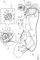
- Fig. 1 is a schematic, pictorial illustration of a catheter-based cardiac diagnostics and/or therapeutic system 20 comprising a balloon catheter 21, in accordance with an embodiment of the present invention.
- Physician 30 inserts a shaft 22 of catheter 21 through the vascular system of a patient 28 through a sheath 23. The physician then navigates a distal end 22a of shaft 22 to a target location inside a heart 26 of the patient.
- physician 30 retracts sheath 23 and expands balloon 40, typically by pumping in saline. Physician 30 then manipulates shaft 22 such that a distal set of electrodes 50, disposed on balloon catheter 40, engage an interior wall of a PV ostium 46 in a left atrium 45, seen in inset 25. If a bipolar EP sensor detects a presence of an arrhythmogenic tissue, high-voltage bipolar IRE pulses are then applied to ostium 46.
- distal electrodes 50 can be brought in contact with tissue.
- the disclosed set of proximal electrodes 52 is not in contact with tissue.
- Some of proximal electrodes 52 are interconnected together via conductors 53, for example by using switching circuitry 36 of console 24, to form the aforementioned common electrode (e.g., for bipolar EP sensing and IRE ablation) that is immersed in blood.
- all of the proximal electrodes 52 are connected together via respective conductors 53 to the switching circuitry 36.
- the proximal end of catheter 21 is connected to a console 24 comprising a processor 41, typically a general-purpose computer, with suitable front end and interface circuits 37 for receiving signals from catheter 21 and from external electrodes 49, which are typically placed around the chest of patient 26.
- processor 41 is connected to external electrodes 49 by wires running from interface circuits 37 through a cable 39.
- Console 24 further comprises an IRE pulse generator 38 configured to apply bipolar IRE pulses between electrodes 50 and interconnected proximal electrodes 52. Both sets of electrodes are connected to IRE pulse generator 38 by electrical wiring running in shaft 22 of catheter 21.
- a memory 48 of console 24 stores IRE protocols comprising IRE pulse parameters, such as peak voltage and pulse width.
- system 20 can track the respective locations of electrodes 50 inside heart 26, using the Advanced Catheter Location (ACL) method, provided by Biosense-Webster (Irvine, California), which is described in US Patent 8,456,182 , whose disclosure is incorporated herein by reference.
- ACL Advanced Catheter Location
- Processor 41 is typically programmed in software to carry out the functions described herein.
- the software may be downloaded to the computer in electronic form, over a network, for example, or it may, alternatively or additionally, be provided and/or stored on non-transitory tangible media, such as magnetic, optical, or electronic memory.
- processor 41 runs a dedicated algorithm as disclosed herein, including Fig. 3 , that enables processor 41 to perform the disclosed steps, as further described below.
- system 20 is capable of performing any of the aforementioned tasks of position and/or ordination tracking of balloon 40, tissue-contact sensing, bipolar electrophysiological (EP) sensing, and bipolar irreversible electroporation (IRE) and/or radiofrequency (RF) ablation, such as of PV ostium 46 tissue of heart 26.
- EP bipolar electrophysiological
- IRE bipolar irreversible electroporation
- RF radiofrequency
- Proximal electrodes 52 can therefore be interconnected by circuitries other than circuit 36. Switching elements to interconnect electrodes 52 may be realized by various electronic devices located at various places of the system, including, for example, within catheter 21.
- the different interface circuitry and/or switching circuitry elements of the system shown in Fig. 1 may be implemented using suitable hardware, such as using one or more discrete components (e.g., a solid-state relay) or one or more Application-Specific Integrated Circuits (ASICs).
- suitable hardware such as using one or more discrete components (e.g., a solid-state relay) or one or more Application-Specific Integrated Circuits (ASICs).
- discrete components e.g., a solid-state relay
- ASICs Application-Specific Integrated Circuits
- Fig. 2 is a schematic, pictorial illustration of balloon catheter 40 used in Fig. 1 , the balloon catheter comprising distal electrodes 50 and proximal electrodes 52, in accordance with an embodiment of the present invention.
- the catheter 40 extends along a longitudinal axis L-L from a proximal location (closest to an operator) to a distal location furthest away from the operator along the axis L-L.
- portion 42a may be considered with respect to portion 42b as a "distal" portion while portion 42b may be considered a "proximal" portion.
- Each pair of a distal electrode 50 and a respective proximal electrode 52 is disposed on a flexible PCB 54 that adheres to a membrane 42 of balloon 40.
- Each distal electrode is connected with a respective conductor 51
- each proximal electrode is connected with a respective conductor 53. Additional conductors, such as to temperature sensors, and which may together form a conductor ribbon with conductors 51/53, are not shown for clarity of presentation.
- Conductors 51/53 are glued (57) at their proximal part (glue layer not shown) to the balloon and are coupled (58) to wires running inside shaft 22a (wires not shown).
- each of electrodes 50 and 52 is connected by its own conductor, for example to a respective wire running to switching circuitry 36 of system 20.
- proximal electrodes 52 are interconnected by switching circuitry 36 in console 24.
- Omitted elements may include, but are not limited to, (i) conductive vias extending through the substrate to electrically couple the electrodes to conductors 51 and 53, (ii) a yarn layer between membrane 42 and flexible PCB substrate 54 to lower the risk of delamination or tearing flexible PCB 54, and (iii) edge layer of flexible substrate 54, added to increase adhesion of flexible substrate 54 to membrane 42, after flexible substrate 54 is glued to membrane 43. Additional functional elements that may be disposed over balloon 40, such as temperature sensors and irrigation holes, are also omitted for clarity of presentation.
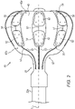
- Fig. 3 is a schematic, pictorial illustration of a basket catheter 340 that can be used with system 20 of in Fig. 1 , the basket catheter comprising distal electrodes 350 and proximal electrodes 352, in accordance with an embodiment of the present invention.
- the catheter 340 extends along a longitudinal axis L-L 362 from a proximal location (closest to an operator) to a distal location furthest away from the operator along the axis L-L.
- Catheter 340 comprises a plurality of expandable spines 354 disposed about longitudinal axis 362.
- Distal end 365 of a shaft 322 can slide on a guidewire 360.
- Guidewire 360 extends through a lumen in shaft 322.
- Each pair of a distal electrode 350 and a respective proximal electrode 352 is disposed on a flexible PCB 355 that that adheres to spine 354 of catheter 340.
- Each distal electrode is connected with a respective conductor 351, and each proximal electrode is connected with a respective conductor 353.
- Additional conductors, such as to temperature sensors, and which may together form a conductor ribbon with conductors 351/353, are not shown for clarity of presentation.
- Conductors 351/353 are glued (glue not shown) at their proximal part to the inner side of the spines and are coupled to wires running inside shaft a 322 (wires not shown).
- each of electrodes 350 and 352 is connected by its own conductor, for example to a respective wire running to switching circuitry 36 of system 20.
- proximal electrodes 352 are interconnected by switching circuitry 36 in console 24.
- Omitted elements may include, but are not limited to, (i) conductive vias extending through the spines to electrically couple the electrodes to conductors 351 and 353, (ii) a yarn layer between spines 354 and flexible PCB substrate 355 to lower the risk of delamination or tearing flexible PCB 355, and (iii) edge layer of flexible substrate 355, added to increase adhesion of flexible substrate 355 to spines 354, after flexible substrate 355 is glued to the spines. Additional functional elements that may be disposed over basket 340, such as temperature sensors and irrigation holes, are also omitted for clarity of presentation.
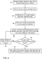
- Fig. 4 is a flow chart that schematically illustrates a method for applying bipolar EP sensing and IRE pulses using balloon (40) catheter 21 of Fig. 1 , in accordance with an embodiment of the invention.
- the algorithm carries out a process that begins when physician 30 navigates the balloon catheter to a target tissue location in an organ of a patient, such as at PV ostium 46, using, for example, electrodes 50 as ACL sensing electrodes, at a balloon catheter navigation step 80.
- physician 30 positions the balloon catheter at ostium 46, at a balloon catheter positioning step 82. Then physician 30 fully inflates balloon 40 to contact target tissue with electrodes 50 over an entire circumference of PV ostium 46, at a balloon inflation step 84.
- processor 41 commands switching circuitry 36 to interconnect all proximal electrodes 52, one with the other, to form a common electrode.
- system 20 acquires bipolar EP potentials between distal electrodes 50 and the common electrode 52 over an entire circumference of balloon 40 to search for arrhythmogenic tissue.
- a checking step 90 analysis determines that the EP signals are normal, or at least not sufficiently indictive of an EP aberrant tissue, physician 30 moves the catheter to another cardiac location, at a catheter moving step 92, and the process returns to step 88.
- physician 30 operates system 20 to apply bipolar IRE pulses between distal electrodes 50 and the common electrode 52 to ablate tissue over the circumference of balloon 40, at an IRE ablation step 94, to isolate an arrhythmia.
Landscapes
- Health & Medical Sciences (AREA)
- Life Sciences & Earth Sciences (AREA)
- Surgery (AREA)
- Engineering & Computer Science (AREA)
- Animal Behavior & Ethology (AREA)
- Veterinary Medicine (AREA)
- Biomedical Technology (AREA)
- Heart & Thoracic Surgery (AREA)
- Medical Informatics (AREA)
- Molecular Biology (AREA)
- Physics & Mathematics (AREA)
- Public Health (AREA)
- General Health & Medical Sciences (AREA)
- Pathology (AREA)
- Biophysics (AREA)
- Cardiology (AREA)
- Plasma & Fusion (AREA)
- Nuclear Medicine, Radiotherapy & Molecular Imaging (AREA)
- Otolaryngology (AREA)
- Physiology (AREA)
- Surgical Instruments (AREA)
- Measurement And Recording Of Electrical Phenomena And Electrical Characteristics Of The Living Body (AREA)
Abstract
Description
- The present invention relates generally to invasive medical probes, and particularly to catheters comprising expandable frames for cardiac applications.
- Electrical elements disposed on a flexible printed circuit board (PCB) that is coupled to a distal end of a medical probe, were previously proposed in the patent literature. For example,
U.S. Patent 10,660,700 - As another example,
U.S. Patent 10,201,311 - An embodiment of the present invention that is described hereinafter provides a catheter including a shaft, an expandable frame, a first set of electrodes, and a second set of electrodes. The shaft is configured for insertion into an organ of a patient. The expandable frame is fitted at a distal end of the shaft. The first set of electrodes is disposed over a distal portion of the expandable frame, and configured to be placed in contact with a tissue in the organ. The second set of electrodes is disposed on a proximal portion of the expandable frame, and configured to be inter-connected to form a common electrode.
- In some embodiments, the expandable frame is shaped to prevent the second set of electrodes from being in contact with the tissue.
- In some embodiments, the expandable frame includes a membrane of an inflatable balloon. In other embodiments, the expandable frame includes spines of an expandable basket catheter.
- In an embodiment, the second set of electrodes is distributed equiangularly about the longitudinal axis of the distal end.
- In some embodiments, the organ is a heart, and the tissue is a pulmonary vein (PV) ostium tissue.
- There is additionally provided, in accordance with another embodiment of the present invention, a system including a catheter and a switching circuitry. The catheter includes a shaft, an expandable frame, a first set of electrodes, and a second set of electrodes. The shaft is configured for insertion into an organ of a patient. The expandable frame is fitted at a distal end of the shaft. The first set of electrodes is disposed over a distal portion of the expandable frame, and configured to be placed in contact with a tissue in the organ. The second set of electrodes is disposed on a proximal portion of the expandable frame, and configured to be inter-connected to form a common electrode. The expandable frame is configured to be inter-connected to form a common electrode. The switching circuitry is configured to inter-connect at least some of the electrodes of the second set with one another to form the common electrode.
- In some embodiments, the system further includes a processor configured to control the switching circuitry.
- In an embodiment, the processor is configured to perform, using the switching circuitry, one or both of acquiring bipolar electrophysiological (EP) signals and applying bipolar ablation signals.
- There is further provided, in accordance with another embodiment of the present invention, a method including inserting into an organ of a patient a catheter including a shaft, an expandable frame fitted at a distal end of the shaft, a first set of electrodes disposed over a distal portion of the expandable frame, and a second set of electrodes disposed on a proximal portion of the expandable frame. The first set of electrodes is placed in contact with the tissue in the organ. At least some of the electrodes of the second set are inter-connected with one another to form a common electrode. One or both of acquiring and applying signals are performed between the first set of electrodes and the common electrode.
- In some embodiments, acquiring the signals includes acquiring bipolar electrophysiological (EP) signals.
- In some embodiments, applying the signals includes applying bipolar ablation signals.
- In an embodiment, the organ is a heart and the tissue include a pulmonary vein (PV) ostium tissue.
- The present invention will be more fully understood from the following detailed description of the embodiments thereof, taken together with the drawings in which:
-
-
Fig. 1 is a schematic, pictorial illustration of a catheter-based cardiac diagnostics and/or therapeutic system comprising a balloon catheter, in accordance with an embodiment of the present invention; -
Fig. 2 is a schematic, pictorial illustration of the balloon catheter used inFig. 1 , the balloon catheter comprising distal electrodes and proximal electrodes, in accordance with an embodiment of the present invention; -
Fig. 3 is a schematic, pictorial illustration of a basket catheter that can be used with system of inFig. 1 , the basket catheter comprising distal electrodes and proximal electrodes, in accordance with an embodiment of the present invention; and -
Fig. 4 is a flow chart that schematically illustrates a method for applying bipolar EP sensing and IRE pulses using the balloon catheter ofFig. 1 , in accordance with an embodiment of the invention. - An expandable frame (e.g., balloon or basket) fitted on a distal end of a catheter may be navigated through the cardiovascular system and inserted into a heart to perform diagnosis and/or ablation of a cardiac tissue using electrodes disposed on the frame.
- The multiple electrodes can be used for tasks such as position and/or orientation tracking of the expandable frame, tissue-contact sensing, bipolar electrophysiological (EP) sensing and bipolar irreversible electroporation (IRE) and/or radiofrequency (RF) ablation.
- Some of the above tasks, e.g., some forms of contact sensing, EP-sensing and IRE/RF ablation, typically make use of a "return" or "common" electrode. Such an electrode may be fitted on the catheter itself and in that case the sensing and ablation are bipolar. An additional electrode (e.g., a ring electrode) could be fitted on a distal end of a shaft of the catheter, just proximally to the expandable frame, and used as a common or return electrode. However, the need for such a ring electrode complicates the catheter, by adding manufacturing steps and special components and due to the limitations on the collapsed diameter and rigid length, a ring electrode is limited in surface area.
- Embodiments of the present invention that are described hereinafter provide expandable frames with a first set of electrodes, called "distal electrodes," disposed on a distal portion of the expandable frame, and a second set of respective electrodes, called "proximal electrodes," disposed on a proximal portion of the expandable frame. The distal electrodes can be brought into contact with tissue and used for EP diagnostics and/or ablation. The proximal electrodes are located over the frame such that they are not in contact with tissue, and are jointly used as a return or common electrode.
- In some embodiments, the distal and proximal sets of electrodes are arranged in electrode pairs, each pair comprising a distal and proximal electrode. The electrode pair is disposed (e.g., by being attached, plated, printed, deposited or patterned) onto a flexible printed circuit board (PCB). In an embodiment, the proximal set of electrodes is distributed equiangularly about a longitudinal axis of the distal end. For balloon catheters, each PCB is cemented to a balloon membrane. To this end, each of the flexible PCBs has an extended shape such that distal and proximal portions cover distal and proximal regions of the balloon, respectively.
- In an embodiment, the proximal electrodes are all electrically interconnected to make one common proximal electrode, to, for example, replace a proximal ring electrode. In another embodiment, the proximal electrodes are selectively connected one with the other.
- Typically, the proximal electrodes are interconnected using switching circuitry that can be comprised in interface circuitries, in a switching box, or in an ablation generator. In an embodiment, the proximal electrodes have permanent electrical interconnections by way of conductive links between them.
- By providing a technique to realize a proximal common electrode with a flexible PCB, the cost of a one-time use multiple-electrode catheter can be significantly reduced.
-
Fig. 1 is a schematic, pictorial illustration of a catheter-based cardiac diagnostics and/ortherapeutic system 20 comprising a balloon catheter 21, in accordance with an embodiment of the present invention.Physician 30 inserts ashaft 22 of catheter 21 through the vascular system of a patient 28 through asheath 23. The physician then navigates adistal end 22a ofshaft 22 to a target location inside aheart 26 of the patient. - Once
distal end 22a ofshaft 22 has reached the target location,physician 30 retractssheath 23 and expandsballoon 40, typically by pumping in saline.Physician 30 then manipulatesshaft 22 such that a distal set ofelectrodes 50, disposed onballoon catheter 40, engage an interior wall of aPV ostium 46 in aleft atrium 45, seen ininset 25. If a bipolar EP sensor detects a presence of an arrhythmogenic tissue, high-voltage bipolar IRE pulses are then applied toostium 46. - In more detail, due to the flattened shape of the distal portion of balloon 40 (as seen in inset 27),
distal electrodes 50 can be brought in contact with tissue. At the same time, the disclosed set ofproximal electrodes 52 is not in contact with tissue. Some ofproximal electrodes 52 are interconnected together viaconductors 53, for example by using switchingcircuitry 36 ofconsole 24, to form the aforementioned common electrode (e.g., for bipolar EP sensing and IRE ablation) that is immersed in blood. Alternatively, all of theproximal electrodes 52 are connected together viarespective conductors 53 to the switchingcircuitry 36. - Certain aspects of inflatable balloons are addressed, for example, in
U.S. Provisional Patent Application 62/899,259, filed September 12, 2019 U.S. Patent application 16/726,605, filed December 24, 2019 U.S. Patent application 16/892,514, filed June 4, 2020 - The proximal end of catheter 21 is connected to a
console 24 comprising aprocessor 41, typically a general-purpose computer, with suitable front end andinterface circuits 37 for receiving signals from catheter 21 and fromexternal electrodes 49, which are typically placed around the chest ofpatient 26. For this purpose,processor 41 is connected toexternal electrodes 49 by wires running frominterface circuits 37 through acable 39. -
Console 24 further comprises anIRE pulse generator 38 configured to apply bipolar IRE pulses betweenelectrodes 50 and interconnectedproximal electrodes 52. Both sets of electrodes are connected toIRE pulse generator 38 by electrical wiring running inshaft 22 of catheter 21. Amemory 48 ofconsole 24 stores IRE protocols comprising IRE pulse parameters, such as peak voltage and pulse width. - During a procedure,
system 20 can track the respective locations ofelectrodes 50 insideheart 26, using the Advanced Catheter Location (ACL) method, provided by Biosense-Webster (Irvine, California), which is described inUS Patent 8,456,182 , whose disclosure is incorporated herein by reference. -
Processor 41 is typically programmed in software to carry out the functions described herein. The software may be downloaded to the computer in electronic form, over a network, for example, or it may, alternatively or additionally, be provided and/or stored on non-transitory tangible media, such as magnetic, optical, or electronic memory. - In particular,
processor 41 runs a dedicated algorithm as disclosed herein, includingFig. 3 , that enablesprocessor 41 to perform the disclosed steps, as further described below. - In general, in the embodiment described herein, using a first set of
distal electrodes 50 and a second set ofproximal electrodes 52, both sets being disposed onballoon 40 of catheter 21,system 20 is capable of performing any of the aforementioned tasks of position and/or ordination tracking ofballoon 40, tissue-contact sensing, bipolar electrophysiological (EP) sensing, and bipolar irreversible electroporation (IRE) and/or radiofrequency (RF) ablation, such as ofPV ostium 46 tissue ofheart 26. - The system of
Fig. 1 is brought by way of example.Proximal electrodes 52 can therefore be interconnected by circuitries other thancircuit 36. Switching elements to interconnectelectrodes 52 may be realized by various electronic devices located at various places of the system, including, for example, within catheter 21. - In various embodiments, the different interface circuitry and/or switching circuitry elements of the system shown in
Fig. 1 may be implemented using suitable hardware, such as using one or more discrete components (e.g., a solid-state relay) or one or more Application-Specific Integrated Circuits (ASICs). -
Fig. 2 is a schematic, pictorial illustration ofballoon catheter 40 used inFig. 1 , the balloon catheter comprisingdistal electrodes 50 andproximal electrodes 52, in accordance with an embodiment of the present invention. InFig. 2 , thecatheter 40 extends along a longitudinal axis L-L from a proximal location (closest to an operator) to a distal location furthest away from the operator along the axis L-L. For example,portion 42a may be considered with respect toportion 42b as a "distal" portion whileportion 42b may be considered a "proximal" portion. - Each pair of a
distal electrode 50 and a respectiveproximal electrode 52 is disposed on aflexible PCB 54 that adheres to amembrane 42 ofballoon 40. Each distal electrode is connected with arespective conductor 51, and each proximal electrode is connected with arespective conductor 53. Additional conductors, such as to temperature sensors, and which may together form a conductor ribbon withconductors 51/53, are not shown for clarity of presentation. -
Conductors 51/53 are glued (57) at their proximal part (glue layer not shown) to the balloon and are coupled (58) to wires running insideshaft 22a (wires not shown). - In the shown embodiment, each of
electrodes circuitry 36 ofsystem 20. To form the aforementioned common electrode, therefore,proximal electrodes 52 are interconnected by switchingcircuitry 36 inconsole 24. - Numerous elements of the balloon are omitted for clarity of presentation. Omitted elements may include, but are not limited to, (i) conductive vias extending through the substrate to electrically couple the electrodes to
conductors membrane 42 andflexible PCB substrate 54 to lower the risk of delamination or tearingflexible PCB 54, and (iii) edge layer offlexible substrate 54, added to increase adhesion offlexible substrate 54 tomembrane 42, afterflexible substrate 54 is glued to membrane 43. Additional functional elements that may be disposed overballoon 40, such as temperature sensors and irrigation holes, are also omitted for clarity of presentation. -
Fig. 3 is a schematic, pictorial illustration of abasket catheter 340 that can be used withsystem 20 of inFig. 1 , the basket catheter comprisingdistal electrodes 350 andproximal electrodes 352, in accordance with an embodiment of the present invention. - In
Fig. 4 , thecatheter 340 extends along alongitudinal axis L-L 362 from a proximal location (closest to an operator) to a distal location furthest away from the operator along the axis L-L.Catheter 340 comprises a plurality ofexpandable spines 354 disposed aboutlongitudinal axis 362.Distal end 365 of ashaft 322 can slide on aguidewire 360.Guidewire 360 extends through a lumen inshaft 322. - Each pair of a
distal electrode 350 and a respectiveproximal electrode 352 is disposed on aflexible PCB 355 that that adheres tospine 354 ofcatheter 340. Each distal electrode is connected with arespective conductor 351, and each proximal electrode is connected with arespective conductor 353. Additional conductors, such as to temperature sensors, and which may together form a conductor ribbon withconductors 351/353, are not shown for clarity of presentation. -
Conductors 351/353 are glued (glue not shown) at their proximal part to the inner side of the spines and are coupled to wires running inside shaft a 322 (wires not shown). - In the shown embodiment, each of
electrodes circuitry 36 ofsystem 20. To form the aforementioned common electrode, therefore,proximal electrodes 352 are interconnected by switchingcircuitry 36 inconsole 24. - Numerous elements of the basket are omitted for clarity of presentation. Omitted elements may include, but are not limited to, (i) conductive vias extending through the spines to electrically couple the electrodes to
conductors spines 354 andflexible PCB substrate 355 to lower the risk of delamination or tearingflexible PCB 355, and (iii) edge layer offlexible substrate 355, added to increase adhesion offlexible substrate 355 tospines 354, afterflexible substrate 355 is glued to the spines. Additional functional elements that may be disposed overbasket 340, such as temperature sensors and irrigation holes, are also omitted for clarity of presentation. -
Fig. 4 is a flow chart that schematically illustrates a method for applying bipolar EP sensing and IRE pulses using balloon (40) catheter 21 ofFig. 1 , in accordance with an embodiment of the invention. The algorithm, according to the presented embodiment, carries out a process that begins whenphysician 30 navigates the balloon catheter to a target tissue location in an organ of a patient, such as atPV ostium 46, using, for example,electrodes 50 as ACL sensing electrodes, at a ballooncatheter navigation step 80. - Next,
physician 30 positions the balloon catheter atostium 46, at a ballooncatheter positioning step 82. Thenphysician 30 fully inflatesballoon 40 to contact target tissue withelectrodes 50 over an entire circumference ofPV ostium 46, at aballoon inflation step 84. - Next, at a switching
step 86,processor 41commands switching circuitry 36 to interconnect allproximal electrodes 52, one with the other, to form a common electrode. - At an
EP diagnosis step 88,system 20 acquires bipolar EP potentials betweendistal electrodes 50 and thecommon electrode 52 over an entire circumference ofballoon 40 to search for arrhythmogenic tissue. - If, at a checking
step 90, analysis determines that the EP signals are normal, or at least not sufficiently indictive of an EP aberrant tissue,physician 30 moves the catheter to another cardiac location, at acatheter moving step 92, and the process returns to step 88. - If, on the other hand, at a checking
step 90, analysis of the EP signals indicates an arrhythmogenic tissue,physician 30 operatessystem 20 to apply bipolar IRE pulses betweendistal electrodes 50 and thecommon electrode 52 to ablate tissue over the circumference ofballoon 40, at anIRE ablation step 94, to isolate an arrhythmia. - Although the embodiments described herein mainly address cardiac applications, the methods and systems described herein can also be used in other medical applications, such as in neurology and Oncology.
- It will thus be appreciated that the embodiments described above are cited by way of example, and that the present invention is not limited to what has been particularly shown and described hereinabove. Rather, the scope of the present invention includes both combinations and sub-combinations of the various features described hereinabove, as well as variations and modifications thereof which would occur to persons skilled in the art upon reading the foregoing description and which are not disclosed in the prior art. Documents incorporated by reference in the present patent application are to be considered an integral part of the application except that to the extent any terms are defined in these incorporated documents in a manner that conflicts with the definitions made explicitly or implicitly in the present specification, only the definitions in the present specification should be considered.
Claims (13)
- A catheter, comprising:a shaft for insertion into an organ of a patient;an expandable frame extending along a longitudinal axis from a proximal portion to a distal portion, the expandable frame being fitted at a distal end of the shaft;a first set of electrodes disposed over a distal portion of the expandable frame, and configured to be placed in contact with a tissue in the organ; anda second set of electrodes disposed on a proximal portion of the expandable frame; anda switching circuit to connect at least two or more electrodes disposed on the proximal portion to form a common electrode.
- The catheter according to claim 1, wherein the expandable frame is shaped to prevent the second set of electrodes from being in contact with the tissue.
- The catheter according to claim 1, wherein the expandable frame comprises a membrane of an inflatable balloon.
- The catheter according to claim 1, wherein the expandable frame comprises spines of an expandable basket catheter.
- The catheter according to claim 1, wherein the second set of electrodes is distributed equiangularly about the longitudinal axis of the expandable frame.
- The catheter according to claim 1, wherein the organ comprises a heart and the tissue comprises a pulmonary vein (PV) ostium tissue.
- A system, comprising:a catheter, comprising:a shaft for insertion into an organ of a patient;an expandable frame extending along a longitudinal axis from a proximal portion to a distal portion, the expandable frame being fitted at a distal end of the shaft;a first set of electrodes disposed over a distal portion of the expandable frame, and configured to be placed in contact with a tissue in the organ; anda second set of electrodes disposed on a proximal portion of the expandable frame, and configured to be inter-connected to form a common electrode not in contact with tissues; anda switching circuitry that inter-connects at least some of the electrodes of the second set with one another to form the common electrode.
- The system according to claim 7, and comprising a processor configured to control the switching circuitry.
- The system according to claim 8, wherein the processor is configured to perform, using the switching circuitry, one or both of acquiring bipolar electrophysiological (EP) signals and applying bipolar ablation signals.
- A method, comprising:inserting into an organ of a patient a catheter, comprising:a shaft;an expandable frame fitted at a distal end of the shaft;a first set of electrodes disposed over a distal portion of the expandable frame; anda second set of electrodes disposed on a proximal portion of the expandable frame;placing the first set of electrodes in contact with the tissue in the organ;inter-connecting at least some of the electrodes of the second set with one another to form a common electrode; andperforming one or both of acquiring and applying signals between the first set of electrodes and the common electrode.
- The method according to claim 10, wherein acquiring the signals comprises acquiring bipolar electrophysiological (EP) signals.
- The method according to claim 10, wherein applying the signals comprises applying bipolar ablation signals.
- The method according to claim 10, wherein the organ comprises a heart and the tissue comprises a pulmonary vein (PV) ostium tissue.
Applications Claiming Priority (1)
| Application Number | Priority Date | Filing Date | Title |
|---|---|---|---|
| US17/065,451 US12239364B2 (en) | 2020-10-07 | 2020-10-07 | Printed proximal electrodes of an expandable catheter for use as a common electrode |
Publications (1)
| Publication Number | Publication Date |
|---|---|
| EP3981346A1 true EP3981346A1 (en) | 2022-04-13 |
Family
ID=78085488
Family Applications (1)
| Application Number | Title | Priority Date | Filing Date |
|---|---|---|---|
| EP21201098.7A Pending EP3981346A1 (en) | 2020-10-07 | 2021-10-06 | Printed proximal electrodes of an expandable catheter for use as a common electrode |
Country Status (5)
| Country | Link |
|---|---|
| US (1) | US12239364B2 (en) |
| EP (1) | EP3981346A1 (en) |
| JP (1) | JP7753034B2 (en) |
| CN (1) | CN114288012A (en) |
| IL (1) | IL286985B1 (en) |
Families Citing this family (4)
| Publication number | Priority date | Publication date | Assignee | Title |
|---|---|---|---|---|
| US12551658B2 (en) | 2022-03-25 | 2026-02-17 | St. Jude Medical, Cardiology Division, Inc. | Steerable introducer with slide block divider |
| CA3258598A1 (en) | 2022-06-21 | 2023-12-28 | Alpfa Medical, Inc. | Apparatus and methods for renal denervation |
| EP4593740A2 (en) | 2022-09-30 | 2025-08-06 | Alpfa Medical, Inc. | Apparatus and methods for tissue ablation |
| US20240415558A1 (en) * | 2023-02-27 | 2024-12-19 | St. Jude Medical, Cardiology Division, Inc. | High Density Flat Balloon Catheter |
Citations (5)
| Publication number | Priority date | Publication date | Assignee | Title |
|---|---|---|---|---|
| US8456182B2 (en) | 2008-09-30 | 2013-06-04 | Biosense Webster, Inc. | Current localization tracker |
| US20140058197A1 (en) * | 2008-11-11 | 2014-02-27 | Amr Salahieh | Low Profile Electrode Assembly |
| US10201311B2 (en) | 2013-02-08 | 2019-02-12 | Acutus Medical, Inc. | Expandable catheter assembly with flexible printed circuit board (PCB) electrical pathways |
| US10660700B2 (en) | 2016-04-28 | 2020-05-26 | Biosense Webster (Israel) Ltd. | Irrigated balloon catheter with flexible circuit electrode assembly |
| CN111248996A (en) * | 2019-12-09 | 2020-06-09 | 韦伯斯特生物官能(以色列)有限公司 | Directed irreversible electroporation (IRE) pulses to compensate for cell size and orientation |
Family Cites Families (271)
| Publication number | Priority date | Publication date | Assignee | Title |
|---|---|---|---|---|
| FR1344459A (en) | 1962-10-18 | 1963-11-29 | Method and apparatus for the electrical study of living organisms | |
| US4276874A (en) | 1978-11-15 | 1981-07-07 | Datascope Corp. | Elongatable balloon catheter |
| US4587975A (en) | 1984-07-02 | 1986-05-13 | Cardiac Pacemakers, Inc. | Dimension sensitive angioplasty catheter |
| US4709698A (en) | 1986-05-14 | 1987-12-01 | Thomas J. Fogarty | Heatable dilation catheter |
| EP0249823B1 (en) | 1986-06-16 | 1991-12-18 | Pacesetter AB | Device for the control of a heart pacer using impedance measurement at body tissues |
| US5178957A (en) | 1989-05-02 | 1993-01-12 | Minnesota Mining And Manufacturing Company | Noble metal-polymer composites and flexible thin-film conductors prepared therefrom |
| JP2891032B2 (en) | 1993-03-15 | 1999-05-17 | 日本ゼオン株式会社 | Balloon catheter |
| US5860974A (en) | 1993-07-01 | 1999-01-19 | Boston Scientific Corporation | Heart ablation catheter with expandable electrode and method of coupling energy to an electrode on a catheter shaft |
| US20020002369A1 (en) | 1993-08-23 | 2002-01-03 | Hood Larry L. | Method and apparatus for modifying visual acuity by moving a focal point of energy within a cornea |
| US5582609A (en) | 1993-10-14 | 1996-12-10 | Ep Technologies, Inc. | Systems and methods for forming large lesions in body tissue using curvilinear electrode elements |
| US5797903A (en) | 1996-04-12 | 1998-08-25 | Ep Technologies, Inc. | Tissue heating and ablation systems and methods using porous electrode structures with electrically conductive surfaces |
| US5429617A (en) | 1993-12-13 | 1995-07-04 | The Spectranetics Corporation | Radiopaque tip marker for alignment of a catheter within a body |
| US5584830A (en) | 1994-03-30 | 1996-12-17 | Medtronic Cardiorhythm | Method and system for radiofrequency ablation of cardiac tissue |
| EP0767628B1 (en) | 1994-06-27 | 2004-01-14 | Boston Scientific Limited | Non-linear control systems for heating and ablating body tissue |
| US6690963B2 (en) | 1995-01-24 | 2004-02-10 | Biosense, Inc. | System for determining the location and orientation of an invasive medical instrument |
| US5718241A (en) | 1995-06-07 | 1998-02-17 | Biosense, Inc. | Apparatus and method for treating cardiac arrhythmias with no discrete target |
| US6322558B1 (en) | 1995-06-09 | 2001-11-27 | Engineering & Research Associates, Inc. | Apparatus and method for predicting ablation depth |
| NL1001890C2 (en) | 1995-12-13 | 1997-06-17 | Cordis Europ | Catheter with plate-shaped electrode array. |
| CA2243595A1 (en) | 1996-01-19 | 1997-07-24 | Ep Technologies, Inc. | Multi-function electrode structures for electrically analyzing and heating body tissue |
| US6719755B2 (en) | 1996-10-22 | 2004-04-13 | Epicor Medical, Inc. | Methods and devices for ablation |
| US6024740A (en) | 1997-07-08 | 2000-02-15 | The Regents Of The University Of California | Circumferential ablation device assembly |
| US5971983A (en) | 1997-05-09 | 1999-10-26 | The Regents Of The University Of California | Tissue ablation device and method of use |
| US6012457A (en) | 1997-07-08 | 2000-01-11 | The Regents Of The University Of California | Device and method for forming a circumferential conduction block in a pulmonary vein |
| US6500174B1 (en) | 1997-07-08 | 2002-12-31 | Atrionix, Inc. | Circumferential ablation device assembly and methods of use and manufacture providing an ablative circumferential band along an expandable member |
| US6652515B1 (en) | 1997-07-08 | 2003-11-25 | Atrionix, Inc. | Tissue ablation device assembly and method for electrically isolating a pulmonary vein ostium from an atrial wall |
| US6966908B2 (en) | 1997-07-08 | 2005-11-22 | Atrionix, Inc. | Tissue ablation device assembly and method for electrically isolating a pulmonary vein ostium from an atrial wall |
| US6164283A (en) | 1997-07-08 | 2000-12-26 | The Regents Of The University Of California | Device and method for forming a circumferential conduction block in a pulmonary vein |
| US6997925B2 (en) | 1997-07-08 | 2006-02-14 | Atrionx, Inc. | Tissue ablation device assembly and method for electrically isolating a pulmonary vein ostium from an atrial wall |
| JP3857788B2 (en) | 1997-09-01 | 2006-12-13 | テルモ株式会社 | Cardiovascular information measurement system |
| US6273886B1 (en) * | 1998-02-19 | 2001-08-14 | Curon Medical, Inc. | Integrated tissue heating and cooling apparatus |
| US6093185A (en) | 1998-03-05 | 2000-07-25 | Scimed Life Systems, Inc. | Expandable PMR device and method |
| US6042580A (en) | 1998-05-05 | 2000-03-28 | Cardiac Pacemakers, Inc. | Electrode having composition-matched, common-lead thermocouple wire for providing multiple temperature-sensitive junctions |
| US6522930B1 (en) | 1998-05-06 | 2003-02-18 | Atrionix, Inc. | Irrigated ablation device assembly |
| US6226542B1 (en) | 1998-07-24 | 2001-05-01 | Biosense, Inc. | Three-dimensional reconstruction of intrabody organs |
| US6301496B1 (en) | 1998-07-24 | 2001-10-09 | Biosense, Inc. | Vector mapping of three-dimensionally reconstructed intrabody organs and method of display |
| US6198974B1 (en) | 1998-08-14 | 2001-03-06 | Cordis Webster, Inc. | Bi-directional steerable catheter |
| US6123718A (en) | 1998-11-02 | 2000-09-26 | Polymerex Medical Corp. | Balloon catheter |
| US6171275B1 (en) | 1998-12-03 | 2001-01-09 | Cordis Webster, Inc. | Irrigated split tip electrode catheter |
| US6380957B1 (en) | 1998-12-15 | 2002-04-30 | International Business Machines Corporation | Method of controlling view of large expansion tree |
| US6986744B1 (en) | 1999-02-02 | 2006-01-17 | Transonic Systems, Inc. | Method and apparatus for determining blood flow during a vascular corrective procedure |
| US6702811B2 (en) | 1999-04-05 | 2004-03-09 | Medtronic, Inc. | Ablation catheter assembly with radially decreasing helix and method of use |
| EP1790304B1 (en) | 1999-05-11 | 2016-08-31 | Atrionix, Inc. | Tissue ablation system including a balloon anchor wire |
| US6696844B2 (en) | 1999-06-04 | 2004-02-24 | Engineering & Research Associates, Inc. | Apparatus and method for real time determination of materials' electrical properties |
| US7935108B2 (en) | 1999-07-14 | 2011-05-03 | Cardiofocus, Inc. | Deflectable sheath catheters |
| US6471693B1 (en) | 1999-09-10 | 2002-10-29 | Cryocath Technologies Inc. | Catheter and system for monitoring tissue contact |
| US7020400B2 (en) | 1999-12-24 | 2006-03-28 | Altera Corporation | Multi-wavelength optical communication system |
| US6546935B2 (en) | 2000-04-27 | 2003-04-15 | Atricure, Inc. | Method for transmural ablation |
| US6656174B1 (en) | 2000-07-20 | 2003-12-02 | Scimed Life Systems, Inc. | Devices and methods for creating lesions in blood vessels without obstructing blood flow |
| JP2004520865A (en) | 2000-07-25 | 2004-07-15 | リタ メディカル システムズ インコーポレイテッド | Apparatus for tumor detection and treatment using localized impedance measurements |
| EP1351618B1 (en) | 2001-01-11 | 2006-11-02 | C.R. Bard, Inc. | Ablation catheter |
| US6743225B2 (en) | 2001-03-27 | 2004-06-01 | Uab Research Foundation | Electrophysiologic measure of endpoints for ablation lesions created in fibrillating substrates |
| US6732734B2 (en) | 2001-04-27 | 2004-05-11 | Kuraray Co., Ltd. | Pilot balloon for balloon catheters |
| USD462389S1 (en) | 2001-04-27 | 2002-09-03 | Marie R. Provence | Teaching aid for learning to tell time |
| US20030018327A1 (en) | 2001-07-20 | 2003-01-23 | Csaba Truckai | Systems and techniques for lung volume reduction |
| DE60203806T2 (en) | 2001-08-31 | 2005-10-06 | Boston Scientific Ltd., St. Michael | PERCUTANEOUS PRINGLE OCCLUSION DEVICE |
| US6814733B2 (en) | 2002-01-31 | 2004-11-09 | Biosense, Inc. | Radio frequency pulmonary vein isolation |
| US8774913B2 (en) | 2002-04-08 | 2014-07-08 | Medtronic Ardian Luxembourg S.A.R.L. | Methods and apparatus for intravasculary-induced neuromodulation |
| US7620451B2 (en) | 2005-12-29 | 2009-11-17 | Ardian, Inc. | Methods and apparatus for pulsed electric field neuromodulation via an intra-to-extravascular approach |
| US6997924B2 (en) | 2002-09-17 | 2006-02-14 | Biosense Inc. | Laser pulmonary vein isolation |
| JP2006501957A (en) | 2002-10-04 | 2006-01-19 | クック ウロロジカル インコーポレイテッド | Hard extraction device with wire basket |
| US7306593B2 (en) | 2002-10-21 | 2007-12-11 | Biosense, Inc. | Prediction and assessment of ablation of cardiac tissue |
| US7156816B2 (en) | 2002-11-26 | 2007-01-02 | Biosense, Inc. | Ultrasound pulmonary vein isolation |
| US6893433B2 (en) | 2002-12-11 | 2005-05-17 | Cryocor, Inc. | System and method for performing a single step cryoablation |
| WO2004073505A2 (en) | 2003-02-20 | 2004-09-02 | Prorhythm, Inc. | Cardiac ablation devices |
| US7142903B2 (en) | 2003-03-12 | 2006-11-28 | Biosense Webster, Inc. | Catheter with contractable mapping assembly |
| US6987995B2 (en) | 2003-03-12 | 2006-01-17 | Biosense Webster, Inc. | Multifunctional catheter handle |
| US7293562B2 (en) | 2003-03-27 | 2007-11-13 | Cierra, Inc. | Energy based devices and methods for treatment of anatomic tissue defects |
| JP2005052424A (en) | 2003-08-05 | 2005-03-03 | Matsushita Electric Ind Co Ltd | Ultrasonic diagnostic equipment |
| US7682521B2 (en) | 2003-08-22 | 2010-03-23 | The Regents Of The University Of Colorado | Aligned liquid crystal thin films and glasses |
| US8292943B2 (en) | 2003-09-03 | 2012-10-23 | Bolton Medical, Inc. | Stent graft with longitudinal support member |
| DE202004021947U1 (en) | 2003-09-12 | 2013-05-13 | Vessix Vascular, Inc. | Selectable eccentric remodeling and / or ablation of atherosclerotic material |
| US7435248B2 (en) | 2003-09-26 | 2008-10-14 | Boston Scientific Scimed, Inc. | Medical probes for creating and diagnosing circumferential lesions within or around the ostium of a vessel |
| US7695491B2 (en) | 2003-12-01 | 2010-04-13 | Ev3 Inc. | Rapid exchange catheters with tandem lumens |
| JP4391221B2 (en) | 2003-12-22 | 2009-12-24 | 有限会社日本エレクテル | High frequency heating balloon catheter |
| US8460286B2 (en) | 2004-01-16 | 2013-06-11 | St. Jude Medical, Atrial Fibrillation Division, Inc. | Conforming electrode |
| US7591799B2 (en) | 2004-06-14 | 2009-09-22 | Biosense Webster, Inc. | Steering mechanism for bi-directional catheter |
| US7377906B2 (en) | 2004-06-15 | 2008-05-27 | Biosense Webster, Inc. | Steering mechanism for bi-directional catheter |
| US9713730B2 (en) | 2004-09-10 | 2017-07-25 | Boston Scientific Scimed, Inc. | Apparatus and method for treatment of in-stent restenosis |
| US8920414B2 (en) * | 2004-09-10 | 2014-12-30 | Vessix Vascular, Inc. | Tuned RF energy and electrical tissue characterization for selective treatment of target tissues |
| US7914487B2 (en) | 2004-10-15 | 2011-03-29 | Futurematrix Interventional, Inc. | Non-compliant medical balloon having braided or knitted reinforcement |
| US8617152B2 (en) | 2004-11-15 | 2013-12-31 | Medtronic Ablation Frontiers Llc | Ablation system with feedback |
| US20060135953A1 (en) | 2004-12-22 | 2006-06-22 | Wlodzimierz Kania | Tissue ablation system including guidewire with sensing element |
| DE102005012739B4 (en) | 2005-03-19 | 2010-09-16 | MAX-PLANCK-Gesellschaft zur Förderung der Wissenschaften e.V. | Method for producing spatial fine structures |
| US7442190B2 (en) | 2005-05-13 | 2008-10-28 | Cryocath Technologies Inc. | Contact assessment of balloon catheters |
| EP1895927A4 (en) | 2005-06-20 | 2011-03-09 | Medtronic Ablation Frontiers | Ablation catheter |
| US7536218B2 (en) | 2005-07-15 | 2009-05-19 | Biosense Webster, Inc. | Hybrid magnetic-based and impedance-based position sensing |
| US7756576B2 (en) | 2005-08-26 | 2010-07-13 | Biosense Webster, Inc. | Position sensing and detection of skin impedance |
| CA2621657C (en) | 2005-09-21 | 2014-06-17 | Surmodics, Inc. | In situ occluding compositions comprising natural biodegradable polysaccharides polymerized by a redox pair |
| US8696656B2 (en) | 2005-11-18 | 2014-04-15 | Medtronic Cryocath Lp | System and method for monitoring bioimpedance and respiration |
| US7842031B2 (en) | 2005-11-18 | 2010-11-30 | Medtronic Cryocath Lp | Bioimpedance measurement system and method |
| US8048032B2 (en) | 2006-05-03 | 2011-11-01 | Vascular Solutions, Inc. | Coaxial guide catheter for interventional cardiology procedures |
| US8677280B2 (en) | 2006-05-18 | 2014-03-18 | Ubiquity Broadcasting Corporation | Sprocket shaped user interface for navigating a dynamic collection of information |
| US20070287994A1 (en) | 2006-06-12 | 2007-12-13 | Pankaj Amrit Patel | Endoscopically Introducible Expandable Bipolar Probe |
| US20100114269A1 (en) | 2006-06-28 | 2010-05-06 | Medtronic Cryocath Lp | Variable geometry balloon catheter and method |
| US8694076B2 (en) | 2006-07-06 | 2014-04-08 | Boston Scientific Scimed, Inc. | Electroactive polymer radiopaque marker |
| US20080051707A1 (en) | 2006-08-25 | 2008-02-28 | Phan Christopher U | Apparatus and methods for use of expandable members in surgical applications |
| US7691080B2 (en) | 2006-09-21 | 2010-04-06 | Mercator Medsystems, Inc. | Dual modulus balloon for interventional procedures |
| ES2407329T3 (en) | 2006-10-18 | 2013-06-12 | Vessix Vascular, Inc. | System to induce desirable temperature effects on body tissue |
| US7867227B2 (en) | 2007-02-22 | 2011-01-11 | A David Slater | Bipolar cardiac ablation system and method |
| US7993537B2 (en) | 2007-02-23 | 2011-08-09 | GM Global Technology Operations LLC | Method for improving adhesion between a shape memory alloy and a polymer |
| US8764742B2 (en) | 2007-04-04 | 2014-07-01 | St. Jude Medical, Atrial Fibrillation Division, Inc. | Irrigated catheter |
| WO2008128070A2 (en) * | 2007-04-11 | 2008-10-23 | The Cleveland Clinic Foundation | Method and apparatus for renal neuromodulation |
| US8496653B2 (en) | 2007-04-23 | 2013-07-30 | Boston Scientific Scimed, Inc. | Thrombus removal |
| US8641704B2 (en) | 2007-05-11 | 2014-02-04 | Medtronic Ablation Frontiers Llc | Ablation therapy system and method for treating continuous atrial fibrillation |
| US20090270850A1 (en) | 2007-06-20 | 2009-10-29 | Tea Time Partners, L.P., Organized In Texas | Devices and methods for the ablation of tissue in the lateral direction |
| US8801703B2 (en) * | 2007-08-01 | 2014-08-12 | Covidien Lp | System and method for return electrode monitoring |
| US9283034B2 (en) | 2007-09-26 | 2016-03-15 | Retrovascular, Inc. | Recanalization system using radiofrequency energy |
| JP2009089806A (en) | 2007-10-05 | 2009-04-30 | Asahi Intecc Co Ltd | Balloon catheter |
| US8357152B2 (en) | 2007-10-08 | 2013-01-22 | Biosense Webster (Israel), Ltd. | Catheter with pressure sensing |
| US9289141B2 (en) | 2007-10-12 | 2016-03-22 | Micropen Technologies Corporation | Apparatus and methods for the measurement of cardiac output |
| US9101431B2 (en) | 2007-11-01 | 2015-08-11 | Stephen B. Murphy | Guide for acetabular component positioning |
| US9717501B2 (en) | 2007-11-21 | 2017-08-01 | St. Jude Medical, Atrial Fibrillation Division, Inc. | Methods and systems for occluding vessels during cardiac ablation including optional electroanatomical guidance |
| US9126023B1 (en) | 2007-12-14 | 2015-09-08 | Gmedelaware 2 Llc | Balloon expandable cement director and related methods |
| US20090163890A1 (en) | 2007-12-20 | 2009-06-25 | Acclarent, Inc. | Method and System for Accessing, Diagnosing and Treating Target Tissue Regions Within the Middle Ear and the Eustachian Tube |
| WO2010033266A2 (en) | 2008-05-02 | 2010-03-25 | Battelle Memorial Institute | Lightweight blast mitigating composite panel |
| DE102008062021A1 (en) | 2008-08-18 | 2010-03-04 | Epcos Ag | Piezo actuator in multilayer construction |
| JP4649506B2 (en) | 2008-09-16 | 2011-03-09 | 有限会社日本エレクテル | High frequency heating balloon catheter |
| US9545216B2 (en) | 2011-08-05 | 2017-01-17 | Mc10, Inc. | Catheter balloon methods and apparatus employing sensing elements |
| US11376061B2 (en) | 2008-11-11 | 2022-07-05 | Covidien Lp | Energy delivery device and methods of use |
| US9795442B2 (en) | 2008-11-11 | 2017-10-24 | Shifamed Holdings, Llc | Ablation catheters |
| US8295902B2 (en) | 2008-11-11 | 2012-10-23 | Shifamed Holdings, Llc | Low profile electrode assembly |
| WO2013154776A2 (en) | 2012-04-13 | 2013-10-17 | Covidien Lp | Energy delivery device and methods of use |
| US20100256629A1 (en) | 2009-04-06 | 2010-10-07 | Voyage Medical, Inc. | Methods and devices for treatment of the ostium |
| US8551096B2 (en) | 2009-05-13 | 2013-10-08 | Boston Scientific Scimed, Inc. | Directional delivery of energy and bioactives |
| US9754025B2 (en) | 2009-08-13 | 2017-09-05 | TunesMap Inc. | Analyzing captured sound and seeking a match based on an acoustic fingerprint for temporal and geographic presentation and navigation of linked cultural, artistic, and historic content |
| US10688278B2 (en) | 2009-11-30 | 2020-06-23 | Biosense Webster (Israel), Ltd. | Catheter with pressure measuring tip |
| US9445859B2 (en) | 2010-01-29 | 2016-09-20 | Medtronic Cryocath Lp | Multifunctional ablation device |
| CN102905639B (en) | 2010-04-06 | 2015-05-06 | 赫莱拉公司 | Systems and methods for lung treatment |
| US9655677B2 (en) * | 2010-05-12 | 2017-05-23 | Shifamed Holdings, Llc | Ablation catheters including a balloon and electrodes |
| US9744339B2 (en) | 2010-05-12 | 2017-08-29 | Circa Scientific, Llc | Apparatus for manually manipulating hollow organs |
| US9173705B2 (en) | 2010-05-13 | 2015-11-03 | Ncontact Surgical, Inc. | Subxyphoid epicardial ablation |
| US20110295247A1 (en) | 2010-05-28 | 2011-12-01 | Hansen Medical, Inc. | System and method for automated minimally invasive therapy using radiometry |
| JP5615073B2 (en) | 2010-07-20 | 2014-10-29 | オムロンヘルスケア株式会社 | measuring device |
| US9463062B2 (en) | 2010-07-30 | 2016-10-11 | Boston Scientific Scimed, Inc. | Cooled conductive balloon RF catheter for renal nerve ablation |
| US8903473B2 (en) | 2010-09-15 | 2014-12-02 | Medtronic, Inc. | Radiopaque markers for implantable medical devices |
| AU2011236083A1 (en) | 2010-10-20 | 2012-05-10 | Maria G. Aboytes | Catheter apparatuses having expandable mesh structures for renal neuromodulation and associated systems and methods |
| CN107007348B (en) | 2010-10-25 | 2019-05-31 | 美敦力Af卢森堡有限责任公司 | Apparatus, system and method for estimation and feedback of neuromodulation therapy |
| CN202654229U (en) | 2010-10-25 | 2013-01-09 | 美敦力Af卢森堡有限责任公司 | Catheter device for curing human patients by renal denervation |
| US9089350B2 (en) | 2010-11-16 | 2015-07-28 | Boston Scientific Scimed, Inc. | Renal denervation catheter with RF electrode and integral contrast dye injection arrangement |
| US20120130646A1 (en) | 2010-11-19 | 2012-05-24 | Lifescan, Inc. | Analyte testing method and system with high and low analyte trends notification |
| US8998893B2 (en) | 2010-12-07 | 2015-04-07 | Boaz Avitall | Catheter systems for cardiac arrhythmia ablation |
| US11246653B2 (en) | 2010-12-07 | 2022-02-15 | Boaz Avitall | Catheter systems for cardiac arrhythmia ablation |
| US9149327B2 (en) | 2010-12-27 | 2015-10-06 | St. Jude Medical Luxembourg Holding S.À.R.L. | Prediction of atrial wall electrical reconnection based on contact force measured during RF ablation |
| US20120191083A1 (en) | 2011-01-20 | 2012-07-26 | Hansen Medical, Inc. | System and method for endoluminal and translumenal therapy |
| US8647358B2 (en) | 2011-01-21 | 2014-02-11 | Obalon Therapeutics Inc. | Intragastric device |
| AU2012225250B2 (en) | 2011-03-10 | 2016-12-08 | Enchannel Medical, Ltd. | Device and method for the geometric determination of electrical dipole densities on the cardiac wall |
| US20140227437A1 (en) | 2011-05-23 | 2014-08-14 | California Institute Of Technology | Accommodating intraocular lens |
| US8975107B2 (en) | 2011-06-16 | 2015-03-10 | Infineon Techologies Ag | Method of manufacturing a semiconductor device comprising a membrane over a substrate by forming a plurality of features using local oxidation regions |
| US9220433B2 (en) | 2011-06-30 | 2015-12-29 | Biosense Webster (Israel), Ltd. | Catheter with variable arcuate distal section |
| DE102011083522B4 (en) | 2011-09-27 | 2015-06-18 | Friedrich-Alexander-Universität Erlangen-Nürnberg | Method and device for visualizing the quality of an ablation procedure |
| CN106823131B (en) | 2011-09-30 | 2019-12-20 | 柯惠有限合伙公司 | Energy transfer device and method of use |
| US8498686B2 (en) | 2011-10-04 | 2013-07-30 | Biosense Webster (Israel), Ltd. | Mapping catheter with spiral electrode assembly |
| DE112012004146T5 (en) | 2011-10-05 | 2014-11-06 | Mc10, Inc. | Cardiac catheter using surface-true electronics for imaging |
| US20130090649A1 (en) | 2011-10-11 | 2013-04-11 | Boston Scientific Scimed, Inc. | Device and methods for renal nerve modulation |
| JP2015503954A (en) | 2011-12-15 | 2015-02-05 | ザ ボード オブ トラスティーズ オブ ザ リーランド スタンフォードジュニア ユニバーシティThe Board of Trustees of the Leland Stanford Junior University | Apparatus and method for treating pulmonary hypertension |
| US9037259B2 (en) | 2011-12-23 | 2015-05-19 | Vessix Vascular, Inc. | Methods and apparatuses for remodeling tissue of or adjacent to a body passage |
| USD682291S1 (en) | 2012-01-08 | 2013-05-14 | In Baek | Display screen with graphical user interface |
| USD682289S1 (en) | 2012-01-08 | 2013-05-14 | Noah DiJulio | Display screen with graphical user interface |
| USD690318S1 (en) | 2012-01-12 | 2013-09-24 | Lenovo (Singapore) Pte. Ltd. | Information handling device with graphical user interface |
| CN109224253A (en) | 2012-03-09 | 2019-01-18 | 明讯科技有限公司 | Medical balloon with radiopaque identifier for precise identification of working surface |
| WO2013148869A1 (en) | 2012-03-27 | 2013-10-03 | Urologix, Inc. | Neuromodulation system and related methods |
| USD729263S1 (en) | 2012-05-02 | 2015-05-12 | Samsung Electronics Co., Ltd. | Display screen or portion thereof with transitional graphical user interface |
| NZ702283A (en) | 2012-06-06 | 2016-09-30 | Loma Vista Medical Inc | Inflatable medical devices |
| USD724618S1 (en) | 2012-06-28 | 2015-03-17 | Samsung Electronics Co., Ltd. | Portable electronic device with a graphical user interface |
| US20140018788A1 (en) | 2012-07-04 | 2014-01-16 | Zoar Jacob ENGELMAN | Devices and Systems for Carotid Body Ablation |
| JP2015521894A (en) | 2012-07-05 | 2015-08-03 | エムシー10 インコーポレイテッドMc10,Inc. | Catheter device including flow sensing |
| US9545290B2 (en) | 2012-07-30 | 2017-01-17 | Ethicon Endo-Surgery, Inc. | Needle probe guide |
| USD720766S1 (en) | 2012-09-10 | 2015-01-06 | Lookout, Inc. | Mobile communication device display with graphical user interface comprising security and privacy advisor screens |
| USD716340S1 (en) | 2012-09-28 | 2014-10-28 | Google Inc. | Display screen or portion thereof for a control unit with animated graphical user interface |
| AU347958S (en) | 2012-10-18 | 2013-04-09 | Samsung Electronics Co Ltd | Display screen for an electronic device |
| USD736780S1 (en) | 2012-12-27 | 2015-08-18 | Lenovo (Beijing) Co., Ltd. | Display screen or portion thereof with animated graphical user interface |
| USD749606S1 (en) | 2012-12-27 | 2016-02-16 | Lenovo (Beijing) Co., Ltd. | Display screen with graphical user interface |
| US9050010B2 (en) | 2012-12-31 | 2015-06-09 | Biosense Webster (Israel) Ltd. | Double loop lasso with single puller wire for bi-directional actuation |
| JP6470185B2 (en) | 2013-01-24 | 2019-02-13 | タイラートン インターナショナル ホールディングス インコーポレイテッドTylerton International Holdings Inc. | Body structure imaging |
| USD694652S1 (en) | 2013-01-30 | 2013-12-03 | MerchSource, LLC | Alarm clock |
| CN105188587A (en) | 2013-03-13 | 2015-12-23 | 波士顿科学医学有限公司 | Steerable ablation device with linear ionically conductive balloon |
| US20140276756A1 (en) | 2013-03-15 | 2014-09-18 | Boston Scientific Scimed, Inc. | Wall-sparing renal nerve ablation catheter with spaced electrode structures |
| US20160000499A1 (en) | 2013-03-15 | 2016-01-07 | Cibiem, Inc. | Endovascular catheters for carotid body ablation utilizing an ionic liquid stream |
| WO2014145148A2 (en) * | 2013-03-15 | 2014-09-18 | Ellman International, Inc. | Surgical instruments and systems with multimodes of treatments and electrosurgical operation |
| US9345540B2 (en) | 2013-03-15 | 2016-05-24 | Medtronic Ablation Frontiers Llc | Contact specific RF therapy balloon |
| US20140275993A1 (en) | 2013-03-15 | 2014-09-18 | Medtronic Ardian Luxembourg S.a.r.I. | Devices, Systems, and Methods for Specialization of Neuromodulation Treatment |
| US10098694B2 (en) | 2013-04-08 | 2018-10-16 | Apama Medical, Inc. | Tissue ablation and monitoring thereof |
| CN110141177B (en) | 2013-04-08 | 2021-11-23 | 阿帕玛医疗公司 | Ablation catheter |
| CN203539434U (en) | 2013-04-12 | 2014-04-16 | 上海微创电生理医疗科技有限公司 | Multi-electrode ablation catheter |
| US20140330266A1 (en) | 2013-05-03 | 2014-11-06 | St. Jude Medical, Cardiology Division, Inc. | Ablation system, methods, and controllers |
| USD740308S1 (en) | 2013-05-23 | 2015-10-06 | Samsung Electronics Co., Ltd. | Display screen or portion thereof with animated graphical user interface |
| USD743424S1 (en) | 2013-06-04 | 2015-11-17 | Abbyy Infopoisk Llc | Display screen or portion thereof with graphical user interface |
| WO2014205388A1 (en) | 2013-06-21 | 2014-12-24 | Boston Scientific Scimed, Inc. | Renal denervation balloon catheter with ride along electrode support |
| US20150005799A1 (en) | 2013-06-27 | 2015-01-01 | Boston Scientific Scimed, Inc. | Renal nerve modulation balloon having improved robustness |
| JP6204579B2 (en) * | 2013-07-01 | 2017-09-27 | ボストン サイエンティフィック サイムド,インコーポレイテッドBoston Scientific Scimed,Inc. | Renal nerve ablation medical device |
| US10342609B2 (en) | 2013-07-22 | 2019-07-09 | Boston Scientific Scimed, Inc. | Medical devices for renal nerve ablation |
| WO2015013301A1 (en) | 2013-07-22 | 2015-01-29 | Boston Scientific Scimed, Inc. | Renal nerve ablation catheter having twist balloon |
| US10722300B2 (en) | 2013-08-22 | 2020-07-28 | Boston Scientific Scimed, Inc. | Flexible circuit having improved adhesion to a renal nerve modulation balloon |
| US9913684B2 (en) | 2013-08-23 | 2018-03-13 | Oscor Inc. | Steerable ablation catheter for renal denervation |
| EP3043733A1 (en) | 2013-09-13 | 2016-07-20 | Boston Scientific Scimed, Inc. | Ablation balloon with vapor deposited cover layer |
| JP5913739B2 (en) | 2013-10-04 | 2016-04-27 | 有限会社日本エレクテル | Balloon catheter ablation system |
| US11246654B2 (en) * | 2013-10-14 | 2022-02-15 | Boston Scientific Scimed, Inc. | Flexible renal nerve ablation devices and related methods of use and manufacture |
| JP6259098B2 (en) | 2013-10-15 | 2018-01-10 | ボストン サイエンティフィック サイムド,インコーポレイテッドBoston Scientific Scimed,Inc. | Medical device and method for manufacturing the medical device |
| US10433902B2 (en) | 2013-10-23 | 2019-10-08 | Medtronic Ardian Luxembourg S.A.R.L. | Current control methods and systems |
| US20150119875A1 (en) | 2013-10-25 | 2015-04-30 | Ablative Solutions, Inc. | Method and apparatus for sparing pain conducting nerves during renal denervation |
| US20150119877A1 (en) | 2013-10-25 | 2015-04-30 | Covidien Lp | Electrode ablation balloon catheter |
| USD744000S1 (en) | 2013-11-18 | 2015-11-24 | Salesforce.Com, Inc. | Display screen or portion thereof with animated graphical user interface |
| US10568686B2 (en) | 2013-11-21 | 2020-02-25 | Biosense Webster (Israel) Ltd. | Multi-electrode balloon catheter with circumferential and point electrodes |
| US9993279B2 (en) | 2013-12-06 | 2018-06-12 | Medtronic Cryocath Lp | Distal balloon impedance and temperature recording to monitor pulmonary vein ablation and occlusion |
| JP2015112114A (en) | 2013-12-06 | 2015-06-22 | 株式会社グッドマン | Nerve potential measurement catheter |
| JP6322402B2 (en) | 2013-12-06 | 2018-05-09 | 株式会社グッドマン | Guiding catheter |
| USD747742S1 (en) | 2013-12-10 | 2016-01-19 | Tencent Technology (Shenzhen) Company Limited | Display screen portion with animated graphical user interface |
| US9855071B2 (en) | 2014-02-03 | 2018-01-02 | Covidien Lp | Thrombectomy catheter system with reference member |
| US9907609B2 (en) | 2014-02-04 | 2018-03-06 | Boston Scientific Scimed, Inc. | Alternative placement of thermal sensors on bipolar electrode |
| US10543039B2 (en) | 2014-03-18 | 2020-01-28 | Boston Scientific Scimed, Inc. | Nerve ablation devices and related methods of use and manufacture |
| US9855089B2 (en) | 2014-03-21 | 2018-01-02 | Medtronic Cryocath Lp | Shape changing ablation balloon |
| US9925359B2 (en) | 2014-03-21 | 2018-03-27 | Medtronic Cryocath Lp | Balloon design to reduce distal length |
| US9956035B2 (en) | 2014-03-27 | 2018-05-01 | Biosense Webster (Israel) Ltd. | Temperature measurement in catheter |
| USD753690S1 (en) | 2014-04-04 | 2016-04-12 | Adp, Llc | Display screen or portion thereof with graphical user interface |
| CA2947433A1 (en) | 2014-04-30 | 2015-11-05 | Michael Flynn | Mobile computing system with user preferred interactive components |
| USD750644S1 (en) | 2014-06-13 | 2016-03-01 | Salesforce.Com, Inc. | Display screen or portion thereof with animated graphical user interface |
| USD759675S1 (en) | 2014-09-11 | 2016-06-21 | Korean Airlines Co., Ltd. | Display screen with animated graphical user interface |
| USD759673S1 (en) | 2014-09-11 | 2016-06-21 | Korean Airlines Co., Ltd. | Display screen with animated graphical user interface |
| KR102288777B1 (en) | 2014-09-22 | 2021-08-11 | 엘지이노텍 주식회사 | Apparatus and Method for Controlling Light |
| USD767616S1 (en) | 2014-09-25 | 2016-09-27 | Google Inc. | Portion of a smart camera display panel with an animated computer icon |
| US10383683B2 (en) | 2014-10-20 | 2019-08-20 | Asahi Medical Technologies, Inc. | Redirecting delivery catheter and methods of use thereof |
| US20160175041A1 (en) | 2014-12-22 | 2016-06-23 | Biosense Webster (Israel) Ltd. | Balloon for ablation around pulmonary veins |
| US10186014B2 (en) | 2015-01-06 | 2019-01-22 | Samsung Electronics Co., Ltd. | Information display method and electronic device for supporting the same |
| US9456914B2 (en) | 2015-01-29 | 2016-10-04 | Intact Vascular, Inc. | Delivery device and method of delivery |
| USD783037S1 (en) | 2015-02-27 | 2017-04-04 | Vigyanlabs Innovations Pvt. Ltd. | Display screen with graphical user interface including a sustainability dashboard for an enterprise |
| US9907610B2 (en) | 2015-05-07 | 2018-03-06 | Biosense Webster (Israel) Ltd. | Spring-loaded balloon |
| JP6857139B2 (en) | 2015-05-12 | 2021-04-14 | ナヴィックス インターナショナル リミテッドNavix International Limited | Region evaluation by dielectric property analysis |
| US11026746B2 (en) | 2015-05-12 | 2021-06-08 | National University Of Ireland, Galway | Devices for therapeutic nasal neuromodulation and associated methods and systems |
| CN107920723B (en) | 2015-06-26 | 2020-01-10 | 阿帕玛医疗公司 | Tissue mapping and visualization system |
| USD768696S1 (en) | 2015-07-28 | 2016-10-11 | Microsoft Corporation | Display screen with animated graphical user interface |
| USD765709S1 (en) | 2015-07-28 | 2016-09-06 | Microsoft Corporation | Display screen with animated graphical user interface |
| USD791805S1 (en) | 2015-08-05 | 2017-07-11 | Cognitive Scale, Inc. | Display screen with a cognitive commerce personal shopping profile graphical user interface |
| WO2017024306A1 (en) | 2015-08-06 | 2017-02-09 | Apama Medical, Inc. | Multipurpose electrode |
| US9744024B2 (en) | 2015-08-06 | 2017-08-29 | Kp Medcure, Inc. | Axial lengthening thrombus capture system |
| JP6817310B2 (en) | 2015-09-17 | 2021-01-20 | ケイジェント ヴァスキュラー, エルエルシーCagent Vascular, Llc | Wedge incision device for medical balloons |
| CN108348146A (en) | 2015-11-16 | 2018-07-31 | 阿帕玛医疗公司 | Energy transmission device |
| US9894756B2 (en) | 2015-12-08 | 2018-02-13 | Kardium Inc. | Circuits for flexible structures |
| US10638976B2 (en) | 2016-04-28 | 2020-05-05 | Biosense Webster (Israel) Ltd | Method of constructing irrigated balloon catheter |
| US20170347896A1 (en) | 2016-06-02 | 2017-12-07 | Biosense Webster (Israel) Ltd. | Balloon catheter and related impedance-based methods for detecting occlusion |
| US10524859B2 (en) * | 2016-06-07 | 2020-01-07 | Metavention, Inc. | Therapeutic tissue modulation devices and methods |
| US10466891B2 (en) | 2016-09-12 | 2019-11-05 | Apple Inc. | Special lock mode user interface |
| US10898262B2 (en) | 2016-10-25 | 2021-01-26 | Biosense Webster (Israel) Ltd. | Catheter distal end made of plastic tube and flexible printed circuit boards |
| US20180161093A1 (en) | 2016-12-08 | 2018-06-14 | Biosense Webster (Israel) Ltd. | Irrigated balloon catheter with support spines and variable shape |
| WO2018106569A1 (en) | 2016-12-09 | 2018-06-14 | St. Jude Medical, Cardiology Division, Inc. | Pulmonary vein isolation balloon catheter |
| JP7033142B2 (en) | 2017-01-06 | 2022-03-09 | セント・ジュード・メディカル,カーディオロジー・ディヴィジョン,インコーポレイテッド | Pulmonary vein isolation balloon catheter |
| US11317965B2 (en) | 2017-03-08 | 2022-05-03 | Biosense Webster (Israel) Ltd. | Reduced size force sensor |
| US20180280080A1 (en) | 2017-03-31 | 2018-10-04 | Biosense Webster (Israel) Ltd. | Balloon catheter with large area electrodes |
| US20180333162A1 (en) | 2017-05-19 | 2018-11-22 | Slec Llc | Subintimal entry catheters and methods for occlusion crossing |
| EP3641684A1 (en) | 2017-06-21 | 2020-04-29 | Apama Medical, Inc. | Graphical user interfaces for ablation systems |
| US11052246B2 (en) * | 2017-07-28 | 2021-07-06 | Medtronic, Inc. | Expandable elements for delivery of electric fields |
| US20190060622A1 (en) | 2017-08-23 | 2019-02-28 | Biosense Webster (Israel) Ltd. | Catheter balloon with integrated wiring |
| US20190059818A1 (en) | 2017-08-29 | 2019-02-28 | Biosense Webster (Israel) Ltd. | Balloon advancement mechanism |
| USD861717S1 (en) | 2017-09-05 | 2019-10-01 | Snap-On Incorporated | Multiprobe circuit tester with animated graphical user interface |
| US10682496B2 (en) | 2017-11-16 | 2020-06-16 | Biosense Webster (Israel) Ltd. | Catheter handle |
| WO2019095020A1 (en) | 2017-11-20 | 2019-05-23 | The Bionics Institute Of Australia | Peripheral nerve electrode array |
| US20190175262A1 (en) | 2017-12-11 | 2019-06-13 | Biosense Webster (Israel) Ltd. | Balloon catheter distal end comprising electrodes and thermocouples |
| US20190175263A1 (en) | 2017-12-12 | 2019-06-13 | Biosense Webster (Israel) Ltd. | Balloon catheter with reverse spiral guidewire |
| US20190183567A1 (en) | 2017-12-19 | 2019-06-20 | Biosense Webster (Israel) Ltd. | Balloon Catheter with Bulbous Shaped Radiofrequency (RF) Ablation Electrodes |
| US10974031B2 (en) | 2017-12-28 | 2021-04-13 | Biosense Webster (Israel) Ltd. | Balloon catheter with internal distal end |
| US10806911B2 (en) | 2018-01-12 | 2020-10-20 | Biosense Webster (Israel) Ltd. | Balloon catheter assisted by pulling a puller-wire |
| US20190298441A1 (en) | 2018-03-28 | 2019-10-03 | Biosense Webster (Israel) Ltd. | Irrigated electrophysiology catheter with distinguishable electrodes for multi-electrode identification and orientation under 2-d visualization |
| US11298082B2 (en) | 2018-05-22 | 2022-04-12 | Biosense Webster (Israel) Ltd. | Catheter with capacitive force sensor |
| US12114906B2 (en) | 2018-06-05 | 2024-10-15 | Boston Scientific Scimed, Inc. | Mapping assembly for cryogenic balloon catheter system |
| US12102781B2 (en) | 2018-06-29 | 2024-10-01 | Biosense Webster (Israel) Ltd. | Reinforcement for irrigated electrophysiology balloon catheter with flexible-circuit electrodes |
| US11672461B2 (en) | 2018-07-16 | 2023-06-13 | Biosense Webster (Israel) Ltd. | Flexible circuit with location and force-sensor coils |
| US11071585B2 (en) | 2018-09-14 | 2021-07-27 | Biosense Webster (Israel) Ltd. | Systems and methods of ablating cardiac tissue |
| US11660050B2 (en) * | 2018-10-25 | 2023-05-30 | Biosense Webster (Israel) Ltd | Balloon catheter with diagnostic electrodes, far field electrodes, and guidewire |
| US11717344B2 (en) | 2018-11-19 | 2023-08-08 | Biosense Webster (Israel) Ltd. | Medical probe with wiring disposed between two expandable membranes |
| US12042216B2 (en) | 2019-12-09 | 2024-07-23 | Biosense Webster (Israel) Ltd. | Irreversible-electroporation (IRE) balloon catheter with membrane-insulated high-voltage balloon wires |
| US12390620B2 (en) | 2019-12-24 | 2025-08-19 | Biosense Webster (Israel) Ltd. | Contact force spring with mechanical stops |
| US20210378734A1 (en) | 2020-06-04 | 2021-12-09 | Biosense Webster (Israel) Ltd. | Smooth-edge and equidistantly spaced electrodes on an expandable frame of a catheter for irreversible-electroporation (ire) |
-
2020
- 2020-10-07 US US17/065,451 patent/US12239364B2/en active Active
-
2021
- 2021-10-05 IL IL286985A patent/IL286985B1/en unknown
- 2021-10-06 EP EP21201098.7A patent/EP3981346A1/en active Pending
- 2021-10-06 JP JP2021164628A patent/JP7753034B2/en active Active
- 2021-10-08 CN CN202111179089.9A patent/CN114288012A/en active Pending
Patent Citations (5)
| Publication number | Priority date | Publication date | Assignee | Title |
|---|---|---|---|---|
| US8456182B2 (en) | 2008-09-30 | 2013-06-04 | Biosense Webster, Inc. | Current localization tracker |
| US20140058197A1 (en) * | 2008-11-11 | 2014-02-27 | Amr Salahieh | Low Profile Electrode Assembly |
| US10201311B2 (en) | 2013-02-08 | 2019-02-12 | Acutus Medical, Inc. | Expandable catheter assembly with flexible printed circuit board (PCB) electrical pathways |
| US10660700B2 (en) | 2016-04-28 | 2020-05-26 | Biosense Webster (Israel) Ltd. | Irrigated balloon catheter with flexible circuit electrode assembly |
| CN111248996A (en) * | 2019-12-09 | 2020-06-09 | 韦伯斯特生物官能(以色列)有限公司 | Directed irreversible electroporation (IRE) pulses to compensate for cell size and orientation |
Also Published As
| Publication number | Publication date |
|---|---|
| IL286985B1 (en) | 2026-04-01 |
| US20220104872A1 (en) | 2022-04-07 |
| IL286985A (en) | 2022-05-01 |
| CN114288012A (en) | 2022-04-08 |
| JP2022061966A (en) | 2022-04-19 |
| JP7753034B2 (en) | 2025-10-14 |
| US12239364B2 (en) | 2025-03-04 |
Similar Documents
| Publication | Publication Date | Title |
|---|---|---|
| US12239465B2 (en) | Balloon catheter with diagnostic electrodes, far field detection electrodes, and guidewire | |
| EP4401517B1 (en) | Electrodes on double-sided printed circuit board (pcb) to cancel far-field signal | |
| US12239364B2 (en) | Printed proximal electrodes of an expandable catheter for use as a common electrode | |
| CN110652356B (en) | Reinforcement for irrigated electrophysiology balloon catheter with flex circuit electrodes | |
| JP7195733B2 (en) | Perfused balloon catheter with supporting spine member and variable geometry | |
| US10925542B2 (en) | Multi-electrode mapping catheter with continuous flex circuit | |
| JP2019202140A (en) | Catheter with capacitive force sensor | |
| EP3957263B1 (en) | Balloon catheter having ablation and return electrodes | |
| EP3895619B1 (en) | Flexible distal-end assembly with double-sided electrode array and irrigation |
Legal Events
| Date | Code | Title | Description |
|---|---|---|---|
| PUAI | Public reference made under article 153(3) epc to a published international application that has entered the european phase |
Free format text: ORIGINAL CODE: 0009012 |
|
| STAA | Information on the status of an ep patent application or granted ep patent |
Free format text: STATUS: THE APPLICATION HAS BEEN PUBLISHED |
|
| AK | Designated contracting states |
Kind code of ref document: A1 Designated state(s): AL AT BE BG CH CY CZ DE DK EE ES FI FR GB GR HR HU IE IS IT LI LT LU LV MC MK MT NL NO PL PT RO RS SE SI SK SM TR |
|
| STAA | Information on the status of an ep patent application or granted ep patent |
Free format text: STATUS: REQUEST FOR EXAMINATION WAS MADE |
|
| 17P | Request for examination filed |
Effective date: 20221012 |
|
| RBV | Designated contracting states (corrected) |
Designated state(s): AL AT BE BG CH CY CZ DE DK EE ES FI FR GB GR HR HU IE IS IT LI LT LU LV MC MK MT NL NO PL PT RO RS SE SI SK SM TR |
|
| STAA | Information on the status of an ep patent application or granted ep patent |
Free format text: STATUS: EXAMINATION IS IN PROGRESS |
|
| 17Q | First examination report despatched |
Effective date: 20250225 |