EP3981278A1 - Shoe - Google Patents
Shoe Download PDFInfo
- Publication number
- EP3981278A1 EP3981278A1 EP19935274.1A EP19935274A EP3981278A1 EP 3981278 A1 EP3981278 A1 EP 3981278A1 EP 19935274 A EP19935274 A EP 19935274A EP 3981278 A1 EP3981278 A1 EP 3981278A1
- Authority
- EP
- European Patent Office
- Prior art keywords
- midsole
- bulging part
- outsole
- outer edge
- shoe
- Prior art date
- Legal status (The legal status is an assumption and is not a legal conclusion. Google has not performed a legal analysis and makes no representation as to the accuracy of the status listed.)
- Granted
Links
Images




Classifications
-
- A—HUMAN NECESSITIES
- A43—FOOTWEAR
- A43B—CHARACTERISTIC FEATURES OF FOOTWEAR; PARTS OF FOOTWEAR
- A43B13/00—Soles; Sole-and-heel integral units
- A43B13/14—Soles; Sole-and-heel integral units characterised by the constructive form
- A43B13/18—Resilient soles
-
- A—HUMAN NECESSITIES
- A43—FOOTWEAR
- A43B—CHARACTERISTIC FEATURES OF FOOTWEAR; PARTS OF FOOTWEAR
- A43B13/00—Soles; Sole-and-heel integral units
- A43B13/02—Soles; Sole-and-heel integral units characterised by the material
- A43B13/12—Soles with several layers of different materials
- A43B13/125—Soles with several layers of different materials characterised by the midsole or middle layer
-
- A—HUMAN NECESSITIES
- A43—FOOTWEAR
- A43B—CHARACTERISTIC FEATURES OF FOOTWEAR; PARTS OF FOOTWEAR
- A43B13/00—Soles; Sole-and-heel integral units
- A43B13/14—Soles; Sole-and-heel integral units characterised by the constructive form
- A43B13/18—Resilient soles
- A43B13/181—Resiliency achieved by the structure of the sole
-
- A—HUMAN NECESSITIES
- A43—FOOTWEAR
- A43B—CHARACTERISTIC FEATURES OF FOOTWEAR; PARTS OF FOOTWEAR
- A43B7/00—Footwear with health or hygienic arrangements
- A43B7/14—Footwear with health or hygienic arrangements with foot-supporting parts
- A43B7/1405—Footwear with health or hygienic arrangements with foot-supporting parts with pads or holes on one or more locations, or having an anatomical or curved form
- A43B7/1415—Footwear with health or hygienic arrangements with foot-supporting parts with pads or holes on one or more locations, or having an anatomical or curved form characterised by the location under the foot
- A43B7/144—Footwear with health or hygienic arrangements with foot-supporting parts with pads or holes on one or more locations, or having an anatomical or curved form characterised by the location under the foot situated under the heel, i.e. the calcaneus bone
-
- A—HUMAN NECESSITIES
- A43—FOOTWEAR
- A43B—CHARACTERISTIC FEATURES OF FOOTWEAR; PARTS OF FOOTWEAR
- A43B7/00—Footwear with health or hygienic arrangements
- A43B7/14—Footwear with health or hygienic arrangements with foot-supporting parts
- A43B7/24—Insertions or other supports preventing the foot canting to one side , preventing supination or pronation
Definitions
- the present invention relates to a shoe, and particularly to a shoe with improved stability.
- Patent Literature 1 Japanese Patent No. 5157020
- Patent Literature 1 Although the shoe described in Patent Literature 1 includes hard embedded portions in the midsole and hence has high stability, some users may be annoyed with a feeling of being pushed up, depending on the users' preferences. Therefore, there is a need for improving the stability by means other than those described in Patent Literature 1.
- the present invention has been made to solve the problem above, and a purpose thereof is to provide a shoe with further improved stability.
- an outsole including a ground contact surface, a midsole fixed onto the outsole, and an upper joined to the midsole along a circumferential edge of the midsole.
- the midsole includes a bulging part at a position corresponding to a medial side of a rearfoot portion, and the bulging part has a bulge length L1 that is measured, in top view, as a horizontal distance from a joint part between the upper and the midsole to an outer edge of the ground contact surface.
- the bulge length L1 is longer than a horizontal length L2 from the joint part between the upper and the midsole to an outer edge of the midsole at the rearmost end.
- an outsole including a ground contact surface, a midsole fixed onto the outsole, and an upper joined to the midsole along a circumferential edge of the midsole.
- the outsole includes a bulging part at a position corresponding to a medial side of a rearfoot portion, and the bulging part has a bulge length L1 that is measured, in top view, as a horizontal distance from a joint part between the outsole and the midsole to an outer edge of the ground contact surface.
- the bulge length L1 is longer than a horizontal length L2 from a joint part between the upper and the midsole to an outer edge of the midsole at the rearmost end.
- front and rear directions (longitudinal directions), width directions, and vertical directions may be used as terms indicating directions. These terms indicate directions viewed from a viewpoint of a wearer wearing a shoe placed on a flat surface. Accordingly, the front direction means a direction toward the toe side, and the rear direction means a direction toward the heel side. Also, a medial side and a lateral side of a foot may also be used as terms indicating directions.
- the medial side of a foot means the inner side of the foot in a width direction, i.e., a longitudinal arch side of the foot, and the lateral side of the foot means the side opposite to the medial side along a width direction.
- outer edges of the midsole and the outsole of a shoe may be referred to.
- the outer edge of the midsole or the outsole means an outer edge of a projected shape of the midsole or the outsole viewed from the top.
- the outside (direction) or the inside (direction) of the midsole may be referred to.
- the outside of the midsole means, when viewed from the top, every direction away from a surface of the midsole.
- the inside of the midsole means, when viewed from the top, every direction from the outside of the midsole toward the inside of a surface of the midsole.
- directions may be described using a three-dimensional Cartesian coordinate system. In this case, the X-axis extends from the medial side toward the lateral side of the foot, the Y-axis extends from the heel side toward the toe side, and the Z-axis extends from the bottom surface side toward the upper side.
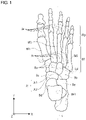
- FIG. 1 Before a shoe according to an embodiment is described, a foot skeleton relevant to the shoe according to the embodiment will be described with reference to FIG. 1 .
- FIG. 1 is a top view of a foot skeleton.
- a human foot is mainly constituted by cuneiform bones Ba, a cuboid bone Bb, a navicular bone Bc, a talus Bd, a calcaneus Be, metatarsal bones Bf, and phalanges Bg.
- Joints of a foot include MP joints Ja, Lisfranc joints Jb, and a Chopart's joint Jc.
- the Chopart's joint Jc includes a calcaneocuboid joint Jc1 formed by the cuboid bone Bb and the calcaneus Be, and a talocalcaneonavicular joint Jc2 formed by the navicular bone Bc and the talus Bd.
- a "forefoot portion" of a wearer means a portion positioned forward of the MP joints Ja and corresponds to a portion between the positions of 0% and about 30% of the entire foot length measured from the toe side.
- a "midfoot portion” means a portion from the MP joints Ja to the Chopart's joint Jc and corresponds to a portion between the positions of about 30% and 80% of the entire foot length measured from the toe side.
- a "rearfoot portion” means a portion positioned rearward of the Chopart's joint Jc and corresponds to a portion between the positions of about 80% and 100% of the entire foot length measured from the toe side.
- a center line S indicates a center line of a shoe and extends along a middle part in a foot width direction.
- the center line S is assumed to be a region positioned on a straight line passing through a third metatarsal bone Bf3 and a medial process Be1 of calcaneal tuberosity of the calcaneus Be in a human body.
- FIG. 1 shows an area in which the medial process Be1 of calcaneal tuberosity is assumed to be positioned.
- FIG. 2 is a side view of a shoe.
- FIG. 2 is a side view of one shoe viewed from the medial side.
- a shoe 1 includes an upper 2 that mainly covers an instep, a midsole 4 to which the upper 2 is joined, and an outsole 6 including a ground contact surface that comes into contact with the ground during walking.
- the upper 2 has a shape that covers a top side of an instep.
- the upper 2 includes an upper body 2a, a tightening means (tightening structure) 2b for the upper, and a slit 2c that extends along a longitudinal direction of the upper 2 around the middle in a width direction of the upper 2.
- a shoe tongue 2d is attached to the upper 2.
- the tightening means 2b a structure constituted by a combination of grommets and a shoelace is employed.
- a hook-and-loop fastener or the like may also be used.
- the upper body 2a may be made of a mesh material obtained by knitting synthetic fiber, such as polyester and polyurethane, or made of synthetic leather or natural leather, for example, and has a shape covering an instep.
- the slit 2c is a buffer portion provided to adjust the width of the upper body 2a by adjusting the degree of tightening of the shoelace. On each side in a width direction of the slit 2c, multiple grommets are provided.
- the shoe tongue 2d is exposed through the slit, and, when a shoelace is tied, the shoelace has no contact with the wearer's instep.
- FIG. 3 is a bottom view of the shoe.
- the outsole 6 may be formed by shaping rubber into a predetermined shape, for example.
- the outsole 6 is pasted over the bottom surface of the midsole 4 such as to cover at least part of the bottom surface of the midsole 4.
- the outsole 6 has the ground contact surface that comes into contact with the ground. On the ground contact surface, a certain rugged pattern is formed, which improves the grip.
- the outsole 6 is formed such that multiple insular portions thereof are pasted onto predetermined positions on the bottom surface of a predetermined midsole.
- the ground contact surface is formed by the bottom surfaces of the multiple insular portions, and the bottom surface of the midsole 4 is exposed between the insular portions. Accordingly, the ground contact surface in the illustrated example does not form a continuous surface and is formed by multiple surfaces.
- the outsole 6 may be formed by one flat sheet member. In this case, the bottom surface of the sheet member forms the ground contact surface.
- the midsole 4 has a function to absorb impact and is formed of a material for absorbing impact, such as expanded EVA, urethane foam, GEL, and cork.
- the midsole 4 has a planar shape approximated to a projected shape of a foot in top view.
- the top surface of the midsole 4 has an uneven shape that corresponds to an uneven shape of the sole of a foot.
- the upper 2 is joined. More specifically, the upper 2 is joined along the outer edge of the midsole 4, or along a line slightly inside the outer edge of the midsole 4.
- the edge of the upper 2 may be sewed onto the midsole 4, or a bonding means, such as an adhesive, may be used for the joining, for example.
- the shape and thickness of the midsole 4 may be appropriately set depending on the use of the shoe.
- FIGS. 4-6 are sectional views of the shoe. More specifically, FIG. 4 is a sectional view taken along line 4-4 in FIG. 2 , FIG. 5 is a sectional view taken along line 5-5 in FIG. 2 , and FIG. 6 is a sectional view taken along line 6-6 in FIG. 2 .
- FIGS. 4-6 shows a cross section around the rearfoot portion viewed from the heel side toward the toe side.
- FIGS. 7 and 8 are schematic sectional views of the midsole viewed from the heel side toward the toe side.
- the midsole 4 includes a bulging part 8 that bulges outward.
- the bulging part 8 may be made by forming a side surface of the midsole 4 into a flare shape that extends outward from the top side toward the lower side, for example. With the bulging part 8 provided, so-called overpronation can be restrained. To maximally restrain the overpronation, the bulging part 8 may be suitably provided at least or only in a portion corresponding to the medial side of the rearfoot portion. Such a bulging part 8 may be formed of the same material as a portion other than the bulging part 8 in the midsole 4 and may have the same hardness as the portion other than the bulging part 8 in the midsole 4.
- the bulging part 8 may be formed of a material different from that of the portion other than the bulging part 8 in the midsole 4 and may have hardness different from that of the portion other than the bulging part 8.
- the relation H1>H2 can be made to hold.
- the feeling of being pushed up can be reduced while the stability can be improved.
- the midsole 4 is formed by two-color molding such that the bulging part 8 and the portion other than the bulging part 8 are integrally formed.
- the bulging part 8 and the midsole 4 may be formed separately and then joined together.
- the bulging part 8 in top view has a shape such that, on the basis of a joint part 10 between the upper 2 and the midsole 4, an outer edge 12 of the bottom surface of the midsole 4 is positioned on the outside of the joint part 10.
- the bulging part 8 is provided only in a portion corresponding to the medial side of the rearfoot portion.
- the bulging part 8 may be provided only in the medial side of the rearfoot portion and the medial side of the forefoot portion.
- the bulging part 8 may be provided only in the medial side of the rearfoot portion, the medial side of the forefoot portion, and the lateral side of the forefoot portion.
- the bulging part 8 may be provided in all the portions other than a portion corresponding to a landing region near the heel part, which will be described later.
- the joint part 10 between the midsole 4 and the upper 2, which serves as a basis for judging whether or not the bulging part 8 is provided, may be different depending on the method of joint between the midsole 4 and the upper 2. More specifically, when the midsole 4 and the upper 2 are sewn together, the midsole 4 and the upper 2 are in surface contact with each other, so that the joint part 10 has a certain width. In this case, on the basis of the contact point between the midsole 4 and the upper 2, when the outer edge 12 of the bottom surface of the midsole 4 is positioned on the outside of the contact point between the midsole 4 and the upper 2, the midsole 4 includes the bulging part 8.
- the top surface of the midsole 4 (the surface to which the upper 2 is joined) can be considered to have an almost flat shape even though it has some asperities.
- the upper 2 has a curved shape such as to wrap an instep, as illustrated in FIGS. 4-6 . Accordingly, on each of the cross sections shown in FIGS. 4-6 , there is a contact point at which the midsole 4 of flat shape is in contact with the upper 2 of curved shape.
- the bulging part 8 can be provided in the midsole 4.
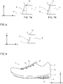
- the height of the bulging part 8 may be the same as the height of the midsole 4 (see FIGS. 7 ) or may be lower than the midsole 4 (see FIG. 8 ).
- FIGS. 7 and 8 schematically illustrates a cross section of the midsole in the interest of clarity, and the angle of each inclined surface is particularly overdrawn.
- the bulging part 8 has a shape obtained by combining, on the X-Z cross section, a horizontal plane extending along the X-Y plane from the joint part 10 between the midsole 4 and the upper 2 toward the outside of the midsole 4 in a horizontal direction, and a vertical plane extending along the Y-Z plane from an end of the horizontal plane toward the bottom surface of the midsole 4 in an almost vertical direction, as illustrated in FIG. 7A , for example.
- the bulging part 8 may have a shape formed by a vertical plane extending along the Y-Z plane from the joint part 10 between the midsole 4 and the upper toward the bottom surface of the midsole 4.
- the vertical plane may be inclined by about ⁇ 3 degrees with respect to a vertical direction.
- the bulging part 8 has a shape obtained by combining, on the X-Z cross section perpendicular to the bulging direction of the bulging part 8 (the direction toward the medial side), a vertical plane extending along the Y-Z plane from a midway in a height direction of the midsole 4 toward the bottom surface of the midsole 4 in an almost vertical direction.
- the bulging part 8 When the height of the bulging part 8 is lower than the midsole 4, the bulging part 8 has a shape that bulges from an arbitrary position in a height direction of the midsole 4 toward the outside of the midsole 4.
- an upper end of the bulging part 8 is positioned midway along a height direction of the midsole 4, and the bulging part 8 has a shape that extends outward of the midsole 4 from the upper end of the bulging part 8 toward the bottom surface of the midsole 4.
- the upper end of the bulging part 8 is provided around the middle in a height direction of the midsole 4.
- FIG. 9 is a side view of the shoe.
- FIG. 9 is a side view of the shoe viewed from the medial side, and the portion where the bulging part is provided is indicated by hatching.
- the bulging part 8 continuously extends in a longitudinal direction from a midway in the midfoot portion to the rearfoot portion.
- the rear end of the bulging part 8 is positioned midway along the rearfoot portion and set not to overlap with the landing region described later.
- the height of the bulging part 8 becomes lower toward the front side.
- the upside of the bulging part 8 is inclined to be away from the upper end of the midsole 4 toward the front side.
- the height of the bulging part 8 may be changed depending on the region.
- the height of the bulging part may be made higher in the rearfoot portion, where the stability is particularly required, and may be made lower toward the front side.
- the bulging part 8 may have a discontinuous shape, such as a shape extending intermittently in a longitudinal direction.
- the outer edge 12 of the midsole 4 may coincide with an outer edge 14 of the outsole 6 having the ground contact surface, when viewed from the top.
- the outer edge 14 of the outsole 6 coinciding with the outer edge 12 of the midsole 4 has at least two patterns as described below.
- the outer edge 14 of the outsole 6 coincides with the outer edge 12 of the midsole 4 when viewed from the top.
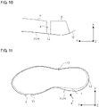
- FIG. 10 is a top view of the outsole 6 and the midsole 4.
- the outer edges 14 of the outsole 6 is indicated by dashed dotted lines
- the outer edge 12 of the midsole 4 is indicated by a dashed double-dotted line
- a portion in which the outer edges 12 and 14 of the outsole 6 and the midsole 4 coincide with each other is indicated by a solid line.
- only part of the outer edge 14 positioned on the outer side of an insular portion of the outsole 6 coincides with part of the outer edge 12 of the midsole 4.
- a bulge length L1 (L1>0) in a horizontal direction of the bulging part 8 is longer than a horizontal length L2 (L2 ⁇ 0) from the joint part 10 between the upper 2 and the midsole 4 to the outer edge 12 of the midsole 4 in a portion where the bulging part 8 is not provided.
- L2 horizontal length
- FIG. 11 is a top view of the midsole.
- the bulge length L1 of the bulging part 8 is a horizontal distance from the joint part 10 between the upper 2 and the midsole 4 to the outer edge 14 of the ground contact surface.
- the bulge length L1 of the bulging part 8 is a distance from the joint part 10 between the upper 2 and the midsole 4 to the outer edge 12 of the midsole 4.
- the horizontal length L2 in a portion where the bulging part 8 is not provided is a horizontal distance from the joint part 10 between the upper 2 and the midsole 4 to the outer edge 12 of the midsole 4.
- the horizontal length L2 may be measured in an arbitrary portion where the bulging part 8 is not provided.
- the bulge length L1 and the horizontal length L2 may change depending on the shape of the midsole 4 and the shape of the joint part 10. In this case, it may be suitable to measure each of the bulge length L1 and the horizontal length L2 at a position where the horizontal distance is largest and then compare the bulge length L1 and the horizontal length L2.
- a horizontal length L3 (L3 ⁇ 0) on the lateral side is a horizontal distance on the lateral side from the joint part 10 between the upper 2 and the midsole 4 to the outer edge 14 of the ground contact surface.
- the bulge length L1 and the horizontal lengths L2 and L3 have only to be measured on the same basis.
- the bulge length L1 and the horizontal lengths L2 and L3 may be measured along the Y-Z plane at a position on the outer edge 12 of the midsole 4.
- the bulge length L1 and the horizontal lengths L2 and L3 may be measured along the Y-Z plane at a position on the joint part 10.
- an arbitrary point may be set at a position along the center line S in the rearfoot portion, for example, and a line may be drawn from the arbitrary point toward the outer edge of the midsole; along the line, the bulge length L1 and the horizontal lengths L2 and L3 may be measured.
- the bulge length L1 of the bulging part 8 is longer than the horizontal lengths L2 and L3 from the joint part 10 between the upper 2 and the midsole 4 to the outer edge 12 of the midsole 4 in a portion where the bulging part 8 is not provided.
- each of the bulge length L1 and the horizontal length L2 may be set to a horizontal distance from the joint part 10 between the upper 2 and the midsole 4 to the outer edge 12 of the midsole 4, regardless of the position of the outer edge 14 of the ground contact surface.
- each of the bulge length L1 and the horizontal length L2 may be set to a horizontal distance from the joint part 10 between the upper 2 and the midsole 4 to the outer edge 14 of the ground contact surface, regardless of the position of the outer edge 12 of the midsole 4.
- FIG. 12 is a bottom view of the midsole and the outsole.
- the bulging part 8 is not provided in a portion corresponding to a landing region 16 near the heel part.
- the portion where the bulging part 8 is not provided may suitably be the portion corresponding to the landing region 16 near the heel part, and the horizontal length L2 may suitably be measured in the portion corresponding to the landing region 16 near the heel part.
- the horizontal length L2 may be measured at an arbitrary position on the lateral side.
- the landing region 16 near the heel part is a region in the bottom surface of the shoe 1 that comes into contact with the ground first when the heel lands, and the landing region 16 may be appropriately set depending on the use of the shoe 1, for example.
- a running shoe for example, it is known that, in a region on the rear side with respect to a virtual line VL1 that traverses in a width direction around the calcaneus as shown in FIG. 12 , the thickness of the midsole 4 is tapered toward the heel side. Accordingly, the vicinity of the heel is tilted toward the heel side with respect to a horizontal direction and/or the lateral side is tilted upward, so that an inclined surface (the landing region 16) is formed.
- the bulging part 8 is not provided in the portion corresponding to the landing region 16 and is provided in a portion other than the portion corresponding to the landing region 16. Not providing the bulging part 8 in the portion corresponding to the landing region 16 prevents the bulging part 8 from disturbing the motion of the foot coming into contact with the ground at the time of landing.
- the horizontal length L2 may suitably be measured in the portion corresponding to the landing region 16, particularly the rearmost part on the heel side.
- the virtual line that defines the landing region 16 may be set to a virtual line VL2 that slants in a longitudinal direction, instead of the virtual line VL1 described above.
- the virtual line VL2 is a slant virtual line in top view, of which the lateral side is positioned forward and the medial side is positioned rearward.
- the slant angle of the virtual line VL2 may be arbitrarily set to an angle between 0 to about 45 degrees with respect to the virtual line VL1.
- the structure for defining the landing region is not limited to the inclined bottom surface of the midsole 4.
- the landing region 16 may be defined by arrangement of multiple insular outsoles 6.
- the outsoles 6 are not formed along the virtual line VL1 or the virtual line VL2 but formed in front of or in the rear of the virtual line VL1 or the virtual line VL2.
- a line on which the bottom surface of the midsole 4 is exposed is formed (see FIG. 3 , for example).
- This line is a portion where the surface of the midsole 4 is exposed when the shoe 1 is viewed from the bottom, and the line has higher flexibility than the portions where the outsoles 6 are formed.
- the region located in the rear of the line may be defined as the landing region 16, and the bulging part 8 is not provided in the portion corresponding to the landing region 16 but may be provided in any other portion.
- the hardness of at least a portion corresponding to the rearfoot portion, particularly a portion positioned below the calcaneus when the shoe is worn is uniform.
- the hardness is made different within the midsole, a boundary between a high hardness portion and a low hardness portion certainly exists.
- the shoe according to the present embodiment can restrain the overpronation by means of the bulging part, even if the hardness of the midsole is made uniform, the overpronation can be suitably restrained.
- FIGS. 13 through 19 are sectional views of the shoe and more specifically are diagrams that each show a modification of the shape of a cross section of the bulging part.
- the bulging part 8 extends from the top surface toward the bottom surface of the midsole 4 such as to form a flare shape in which the inclination angle becomes gentle at an inflection point provided midway along a height direction of the midsole 4.
- the bulging part 8 extends from a midway in a height direction of the midsole 4 toward the medial side and then extends toward the bottom surface such as to form a flare shape.
- the bulging part 8 bulges out from a midway in a height direction of the midsole 4 toward the medial side such as to form a curved shape.
- the bulging part 8 bulges out from a low position in a height direction of the midsole 4 toward the medial side such as to form a curved shape.
- part of the midsole 4 other than the bulging part 8 is also formed of a high hardness material.
- a portion continuous with the bulging part 8 is formed of a high hardness material, and the remaining portion is formed of a low hardness material.
- the portion formed of a high hardness material is indicated by hatching in the interest of clarity.
- the bulging part 8 has the same shape as the bulging part shown in FIG. 13 . Also, in the example shown in FIG.
- the bulging part 8 is formed along the entire length in a height direction of the midsole 4.
- a high hardness material part with which the bulging part 8 have line symmetry is provided.
- the bulging part 8 is formed along the entire length in a height direction of the midsole 4 and has a shape curved toward the medial side.
- a high hardness material part with which the bulging part 8 have line symmetry is provided.
- the high hardness material part extends toward the inside of the midsole to only reach a position that hardly overlaps with the calcaneus when viewed from the top.
- the high hardness material part extends to a position that partially overlaps with the calcaneus when viewed from the top.
- the feeling of being pushed up can be restrained.
- the high hardness material part when the high hardness material part is extended toward the inside of the midsole 4, it may be suitable to extend only the lower side in a height direction and avoid the situation where only the top side in a height direction overlaps with the calcaneus. In this case, it may be more suitable to provide the high hardness material part at a position lower than the middle in a height direction, for example. Further, to suitably prevent the feeling of being pushed up occurring, it may be more suitable that the high hardness material part does not have a shape forming an angle on the top side at a position that overlaps with the calcaneus. Accordingly, the high hardness material part can restrain the feeling of being pushed up.
- the high hardness material part need not necessarily have a shape with which the bulging part 8 have line symmetry.
- the shoe according to the embodiment includes the bulging part 8 provided at a position corresponding to the medial side of the rearfoot portion, the medial side can be firmly supported at the time of landing, and the overpronation can be restrained. Accordingly, the stability can be improved. Also, since the bulging part 8 is not provided in the landing region 16, the bulging part 8 disturbing the landing motion can be prevented.
- the bulging part is provided in the midsole in the aforementioned embodiment, the bulging part is provided in the outsole in the second embodiment.
- FIG. 20 is a sectional view of a shoe.
- a shoe 20 includes a roll-up portion 24 in an outsole 22, and a bulging part 26 is formed on the roll-up portion 24.
- the roll-up portion 24 is formed by a circumferential wall extending upward from an outer edge of the outsole 22. More specifically, the roll-up portion 24 extends upward from the outer edge of the outsole 22.
- the roll-up portion 24 enhances the rigidity of the shoe 20.
- the rigidity of the shoe 20 means the flexural rigidity or torsional rigidity, for example.
- the position of the upper end of the roll-up portion 24 may be appropriately changed depending on the use of the shoe 20.
- the height of the roll-up portion 24 may be uniform or may be different depending on the position. For example, when rigidity is required on the toe side, the roll-up portion 24 may be made lower on the heel side and higher on the toe side. Also, the height of the roll-up portion 24 may be made different between the medial side and the lateral side in a width direction.
- the bulging part 26 may be made by forming a side surface of the outsole 22 into a flare shape that extends outward from the top side toward the lower side. With such a bulging part 26, so-called overpronation can be restrained. With regard to the position of the roll-up portion 24, the roll-up portion 24 may be formed over the entire circumference of the outsole 22 along the outer edge of the outsole 22 or may be formed on only part of the outsole 22 along the outer edge of the outsole 22. Also, the bulging part 26 may be formed, along the outer edge of the outsole 22, over the entire roll-up portion 24 or only part of the roll-up portion 24. The bulging part 26 may be provided only in the portion corresponding to the medial side of the rearfoot portion.
- the bulging part 26 may be provided only in the medial side of the rearfoot portion and the medial side of the forefoot portion. In yet another aspect, the bulging part 26 may be provided only in the medial side of the rearfoot portion, the medial side of the forefoot portion, and the lateral side of the forefoot portion. In a further aspect, the bulging part 26 may be provided in all the portions other than the portion corresponding to the landing region near the heel part.
- the height of the bulging part 26 may be the same as the height of the roll-up portion 24 or may be lower than the roll-up portion 24.
- the bulging part 26 has a shape obtained by combining, on the Y-Z cross section perpendicular to the bulging direction of the bulging part 26, a horizontal plane extending along the X-Y plane from the upper end of the roll-up portion 24 toward the outside of the midsole 28, and a vertical plane extending along the Y-Z plane from an end of the horizontal plane toward the bottom surface of the midsole 28.
- FIGS. 21-23 are sectional views of the shoe, which each show a modification of the bulging part.
- the bulging part 26 has a shape that bulges from an arbitrary position in a height direction of the roll-up portion 24 toward the outside of the roll-up portion 24.
- the height of the roll-up portion 24 is lower than the height of the midsole 28 and the bulging part 26 has the same height as the roll-up portion 24, as illustrated in FIG. 22 .
- the bulging part 26 has a shape obtained by combining, on the Y-Z cross section perpendicular to the bulging direction of the bulging part 26, a horizontal plane extending along the X-Y plane from the upper end of the roll-up portion 24 toward the outside of the midsole 28, and a vertical plane extending almost along the Y-Z plane from an end of the horizontal plane toward the bottom surface of the outsole 22. Also, when the height of the roll-up portion 24 is lower than the height of the midsole 28 and when the height of the bulging part 26 is lower than the height of the roll-up portion 24, as illustrated in FIG. 23 , the bulging part 26 has a shape that bulges from an arbitrary position in a height direction of the roll-up portion 24 toward the outside of the roll-up portion 24.
- the bulging part 26 since the bulging part 26 is provided, the medial side can be firmly supported at the time of landing, and the overpronation can be restrained. Accordingly, the stability can be improved. Also, since the bulging part 26 is not provided in the landing region, the bulging part 26 disturbing the landing motion can be prevented.
- an outsole including a ground contact surface, a midsole fixed onto the outsole, and an upper joined to the midsole along a circumferential edge of the midsole.
- the midsole includes a bulging part at a position corresponding to a medial side of a rearfoot portion, and the bulging part has a bulge length L1 that is measured, in top view, as a horizontal distance from a joint part between the upper and the midsole to an outer edge of the ground contact surface.
- the bulge length L1 is longer than a horizontal length L2 from the joint part between the upper and the midsole to an outer edge of the midsole at the rearmost end.
- the hardness of the bulging part in the first or second aspect is higher than the hardness of a portion other than the bulging part in the midsole.
- the bulging part in any one of the first through third aspects is formed from a joining surface of the midsole and the outsole to a midway in a height direction of the midsole.
- a side surface on the medial side of the bulging part in any one of the first through fourth aspects has a shape that extends away from the joint part toward the ground contact surface.
- the midsole in any one of the first through fifth aspects is formed by two-color molding.
- the bulging part in any one of the first through sixth aspects is formed only in the medial side of the rearfoot portion.
- the bulging part in any one of the first through sixth aspects is formed in a part other than an outer circumference of a landing region near a heel part on the ground contact surface.
- an outsole including a ground contact surface, a midsole fixed onto the outsole, and an upper joined to the midsole along a circumferential edge of the midsole.
- the outsole includes a bulging part at a position corresponding to a medial side of a rearfoot portion, and the bulging part has a bulge length L1 that is measured, in top view, as a horizontal distance from a joint part between the outsole and the midsole to an outer edge of the ground contact surface.
- the bulge length L1 is longer than a horizontal length L2 from a joint part between the upper and the midsole to an outer edge of the midsole at the rearmost end.
- the present invention is applicable to a shoe.
Landscapes
- Health & Medical Sciences (AREA)
- Epidemiology (AREA)
- General Health & Medical Sciences (AREA)
- Public Health (AREA)
- Chemical & Material Sciences (AREA)
- Engineering & Computer Science (AREA)
- Materials Engineering (AREA)
- Footwear And Its Accessory, Manufacturing Method And Apparatuses (AREA)
Abstract
Description
- The present invention relates to a shoe, and particularly to a shoe with improved stability.
- For shoes used for running or walking, both the cushioning properties of absorbing impact at the time of landing and the stability at the time of landing have been conventionally required. Particularly, the stability at the time of landing has been considered important in terms of prevention of injuries. Shoes with low stability may cause so-called overpronation in which a foot excessively tilts toward the medial side at the time of landing, which raises the possibility of getting injured. Therefore, restraining overpronation is extremely important, and, as a technology for the restraint, the technology described in
Patent Literature 1 is known, for example. - Patent Literature 1:
Japanese Patent No. 5157020 - However, although the shoe described in
Patent Literature 1 includes hard embedded portions in the midsole and hence has high stability, some users may be annoyed with a feeling of being pushed up, depending on the users' preferences. Therefore, there is a need for improving the stability by means other than those described inPatent Literature 1. - The present invention has been made to solve the problem above, and a purpose thereof is to provide a shoe with further improved stability.
- According to a first aspect of the present invention, an outsole including a ground contact surface, a midsole fixed onto the outsole, and an upper joined to the midsole along a circumferential edge of the midsole are provided. The midsole includes a bulging part at a position corresponding to a medial side of a rearfoot portion, and the bulging part has a bulge length L1 that is measured, in top view, as a horizontal distance from a joint part between the upper and the midsole to an outer edge of the ground contact surface. The bulge length L1 is longer than a horizontal length L2 from the joint part between the upper and the midsole to an outer edge of the midsole at the rearmost end.
- In another aspect of the present invention, an outsole including a ground contact surface, a midsole fixed onto the outsole, and an upper joined to the midsole along a circumferential edge of the midsole are provided. The outsole includes a bulging part at a position corresponding to a medial side of a rearfoot portion, and the bulging part has a bulge length L1 that is measured, in top view, as a horizontal distance from a joint part between the outsole and the midsole to an outer edge of the ground contact surface. The bulge length L1 is longer than a horizontal length L2 from a joint part between the upper and the midsole to an outer edge of the midsole at the rearmost end.
-
-
FIG. 1 is a top view of a foot skeleton; -
FIG. 2 is a side view of a shoe according to an embodiment; -
FIG. 3 is a bottom view of the shoe according to the embodiment; -
FIG. 4 is a sectional view of the shoe according to the embodiment; -
FIG. 5 is another sectional view of the shoe according to the embodiment; -
FIG. 6 is yet another sectional view of the shoe according to the embodiment; -
FIGS. 7 are schematic sectional views of a midsole of the shoe according to the embodiment; -
FIG. 8 is another schematic sectional view of the midsole of the shoe according to the embodiment; -
FIG. 9 is a side view of the shoe according to the embodiment; -
FIG. 10 is a top view of an outsole and the midsole in the embodiment; -
FIG. 11 is a top view of the midsole in the embodiment; -
FIG. 12 is a bottom view of the midsole and the outsole in the embodiment; -
FIG. 13 is a sectional view of a shoe according to a modification of the embodiment; -
FIG. 14 is a sectional view of a shoe according to another modification of the embodiment; -
FIG. 15 is a sectional view of a shoe according to yet another modification of the embodiment; -
FIG. 16 is a sectional view of a shoe according to still yet another modification of the embodiment; -
FIG. 17 is a sectional view of a shoe according to still yet another modification of the embodiment; -
FIG. 18 is a sectional view of a shoe according to still yet another modification of the embodiment; -
FIG. 19 is a sectional view of a shoe according to a further modification of the embodiment; -
FIG. 20 is a sectional view of a shoe according to a second embodiment; -
FIG. 21 is a sectional view of a shoe according to a modification of the second embodiment; -
FIG. 22 is a sectional view of a shoe according to another modification of the second embodiment; and -
FIG. 23 is a sectional view of a shoe according to yet another modification of the second embodiment. - Definitions of terms used in this specification will be described. In this specification, front and rear directions (longitudinal directions), width directions, and vertical directions may be used as terms indicating directions. These terms indicate directions viewed from a viewpoint of a wearer wearing a shoe placed on a flat surface. Accordingly, the front direction means a direction toward the toe side, and the rear direction means a direction toward the heel side. Also, a medial side and a lateral side of a foot may also be used as terms indicating directions. The medial side of a foot means the inner side of the foot in a width direction, i.e., a longitudinal arch side of the foot, and the lateral side of the foot means the side opposite to the medial side along a width direction.
- Also, in the following description, outer edges of the midsole and the outsole of a shoe may be referred to. The outer edge of the midsole or the outsole means an outer edge of a projected shape of the midsole or the outsole viewed from the top. Also, in the following description, the outside (direction) or the inside (direction) of the midsole may be referred to. The outside of the midsole means, when viewed from the top, every direction away from a surface of the midsole. The inside of the midsole means, when viewed from the top, every direction from the outside of the midsole toward the inside of a surface of the midsole. Further, in some examples, directions may be described using a three-dimensional Cartesian coordinate system. In this case, the X-axis extends from the medial side toward the lateral side of the foot, the Y-axis extends from the heel side toward the toe side, and the Z-axis extends from the bottom surface side toward the upper side.
- Before a shoe according to an embodiment is described, a foot skeleton relevant to the shoe according to the embodiment will be described with reference to
FIG. 1 . -
FIG. 1 is a top view of a foot skeleton. A human foot is mainly constituted by cuneiform bones Ba, a cuboid bone Bb, a navicular bone Bc, a talus Bd, a calcaneus Be, metatarsal bones Bf, and phalanges Bg. Joints of a foot include MP joints Ja, Lisfranc joints Jb, and a Chopart's joint Jc. The Chopart's joint Jc includes a calcaneocuboid joint Jc1 formed by the cuboid bone Bb and the calcaneus Be, and a talocalcaneonavicular joint Jc2 formed by the navicular bone Bc and the talus Bd. In this specification, a "forefoot portion" of a wearer means a portion positioned forward of the MP joints Ja and corresponds to a portion between the positions of 0% and about 30% of the entire foot length measured from the toe side. Also, a "midfoot portion" means a portion from the MP joints Ja to the Chopart's joint Jc and corresponds to a portion between the positions of about 30% and 80% of the entire foot length measured from the toe side. Also, a "rearfoot portion" means a portion positioned rearward of the Chopart's joint Jc and corresponds to a portion between the positions of about 80% and 100% of the entire foot length measured from the toe side. InFIG. 1 , a center line S indicates a center line of a shoe and extends along a middle part in a foot width direction. The center line S is assumed to be a region positioned on a straight line passing through a third metatarsal bone Bf3 and a medial process Be1 of calcaneal tuberosity of the calcaneus Be in a human body.FIG. 1 shows an area in which the medial process Be1 of calcaneal tuberosity is assumed to be positioned. -
FIG. 2 is a side view of a shoe.FIG. 2 is a side view of one shoe viewed from the medial side. As illustrated inFIG. 2 , ashoe 1 includes an upper 2 that mainly covers an instep, amidsole 4 to which the upper 2 is joined, and anoutsole 6 including a ground contact surface that comes into contact with the ground during walking. - The upper 2 has a shape that covers a top side of an instep. The upper 2 includes an
upper body 2a, a tightening means (tightening structure) 2b for the upper, and aslit 2c that extends along a longitudinal direction of the upper 2 around the middle in a width direction of the upper 2. Also, to the upper 2, ashoe tongue 2d is attached. In the present embodiment, as the tightening means 2b, a structure constituted by a combination of grommets and a shoelace is employed. As the tightening means, a hook-and-loop fastener or the like may also be used. - The
upper body 2a may be made of a mesh material obtained by knitting synthetic fiber, such as polyester and polyurethane, or made of synthetic leather or natural leather, for example, and has a shape covering an instep. Theslit 2c is a buffer portion provided to adjust the width of theupper body 2a by adjusting the degree of tightening of the shoelace. On each side in a width direction of theslit 2c, multiple grommets are provided. Theshoe tongue 2d is exposed through the slit, and, when a shoelace is tied, the shoelace has no contact with the wearer's instep. -
FIG. 3 is a bottom view of the shoe. As illustrated inFIG. 3 , theoutsole 6 may be formed by shaping rubber into a predetermined shape, for example. Theoutsole 6 is pasted over the bottom surface of themidsole 4 such as to cover at least part of the bottom surface of themidsole 4. Theoutsole 6 has the ground contact surface that comes into contact with the ground. On the ground contact surface, a certain rugged pattern is formed, which improves the grip. - In the example shown in
FIG. 3 , theoutsole 6 is formed such that multiple insular portions thereof are pasted onto predetermined positions on the bottom surface of a predetermined midsole. The ground contact surface is formed by the bottom surfaces of the multiple insular portions, and the bottom surface of themidsole 4 is exposed between the insular portions. Accordingly, the ground contact surface in the illustrated example does not form a continuous surface and is formed by multiple surfaces. Alternatively, theoutsole 6 may be formed by one flat sheet member. In this case, the bottom surface of the sheet member forms the ground contact surface. - The
midsole 4 has a function to absorb impact and is formed of a material for absorbing impact, such as expanded EVA, urethane foam, GEL, and cork. Themidsole 4 has a planar shape approximated to a projected shape of a foot in top view. The top surface of themidsole 4 has an uneven shape that corresponds to an uneven shape of the sole of a foot. To the top surface of themidsole 4, the upper 2 is joined. More specifically, the upper 2 is joined along the outer edge of themidsole 4, or along a line slightly inside the outer edge of themidsole 4. To join the upper 2 to themidsole 4, the edge of the upper 2 may be sewed onto themidsole 4, or a bonding means, such as an adhesive, may be used for the joining, for example. The shape and thickness of themidsole 4 may be appropriately set depending on the use of the shoe. -
FIGS. 4-6 are sectional views of the shoe. More specifically,FIG. 4 is a sectional view taken along line 4-4 inFIG. 2 ,FIG. 5 is a sectional view taken along line 5-5 inFIG. 2 , andFIG. 6 is a sectional view taken along line 6-6 inFIG. 2 . Each of the sectional views ofFIGS. 4-6 shows a cross section around the rearfoot portion viewed from the heel side toward the toe side.FIGS. 7 and 8 are schematic sectional views of the midsole viewed from the heel side toward the toe side. - As illustrated in
FIGS. 4-6 , themidsole 4 includes abulging part 8 that bulges outward. The bulgingpart 8 may be made by forming a side surface of themidsole 4 into a flare shape that extends outward from the top side toward the lower side, for example. With the bulgingpart 8 provided, so-called overpronation can be restrained. To maximally restrain the overpronation, the bulgingpart 8 may be suitably provided at least or only in a portion corresponding to the medial side of the rearfoot portion. Such abulging part 8 may be formed of the same material as a portion other than the bulgingpart 8 in themidsole 4 and may have the same hardness as the portion other than the bulgingpart 8 in themidsole 4. Also, the bulgingpart 8 may be formed of a material different from that of the portion other than the bulgingpart 8 in themidsole 4 and may have hardness different from that of the portion other than the bulgingpart 8. For example, as shown inFIGS. 4-6 , when the hardness of the bulgingpart 8 is set to H1 and the hardness of the portion other than the bulgingpart 8 is set to H2, the relation H1>H2 can be made to hold. With such a configuration, the feeling of being pushed up can be reduced while the stability can be improved. In such a case, it may be suitable that themidsole 4 is formed by two-color molding such that the bulgingpart 8 and the portion other than the bulgingpart 8 are integrally formed. Also, the bulgingpart 8 and themidsole 4 may be formed separately and then joined together. - From another perspective, it can be described that the bulging
part 8 in top view has a shape such that, on the basis of ajoint part 10 between the upper 2 and themidsole 4, anouter edge 12 of the bottom surface of themidsole 4 is positioned on the outside of thejoint part 10. In theshoe 1 according to the embodiment, the bulgingpart 8 is provided only in a portion corresponding to the medial side of the rearfoot portion. In another aspect, the bulgingpart 8 may be provided only in the medial side of the rearfoot portion and the medial side of the forefoot portion. In yet another aspect, the bulgingpart 8 may be provided only in the medial side of the rearfoot portion, the medial side of the forefoot portion, and the lateral side of the forefoot portion. In a further aspect, the bulgingpart 8 may be provided in all the portions other than a portion corresponding to a landing region near the heel part, which will be described later. - The
joint part 10 between themidsole 4 and the upper 2, which serves as a basis for judging whether or not thebulging part 8 is provided, may be different depending on the method of joint between themidsole 4 and the upper 2. More specifically, when themidsole 4 and the upper 2 are sewn together, themidsole 4 and the upper 2 are in surface contact with each other, so that thejoint part 10 has a certain width. In this case, on the basis of the contact point between themidsole 4 and the upper 2, when theouter edge 12 of the bottom surface of themidsole 4 is positioned on the outside of the contact point between themidsole 4 and the upper 2, themidsole 4 includes the bulgingpart 8. The top surface of the midsole 4 (the surface to which the upper 2 is joined) can be considered to have an almost flat shape even though it has some asperities. Meanwhile, the upper 2 has a curved shape such as to wrap an instep, as illustrated inFIGS. 4-6 . Accordingly, on each of the cross sections shown inFIGS. 4-6 , there is a contact point at which themidsole 4 of flat shape is in contact with the upper 2 of curved shape. By forming themidsole 4 such that, on the basis of a contact point, theouter edge 12 of the bottom surface of themidsole 4 is positioned on the outside of the contact point, the bulgingpart 8 can be provided in themidsole 4. - The height of the bulging
part 8 may be the same as the height of the midsole 4 (seeFIGS. 7 ) or may be lower than the midsole 4 (seeFIG. 8 ). Each ofFIGS. 7 and 8 schematically illustrates a cross section of the midsole in the interest of clarity, and the angle of each inclined surface is particularly overdrawn. When the height of the bulgingpart 8 is the same as the height of themidsole 4, the bulgingpart 8 has a shape obtained by combining, on the X-Z cross section, a horizontal plane extending along the X-Y plane from thejoint part 10 between themidsole 4 and the upper 2 toward the outside of themidsole 4 in a horizontal direction, and a vertical plane extending along the Y-Z plane from an end of the horizontal plane toward the bottom surface of themidsole 4 in an almost vertical direction, as illustrated inFIG. 7A , for example. Also, as illustrated inFIG. 7B , the bulgingpart 8 may have a shape formed by a vertical plane extending along the Y-Z plane from thejoint part 10 between themidsole 4 and the upper toward the bottom surface of themidsole 4. The vertical plane may be inclined by about ±3 degrees with respect to a vertical direction. Meanwhile, when the height of the bulgingpart 8 is not the same as the height of themidsole 4, as illustrated inFIG. 8 , the bulgingpart 8 has a shape obtained by combining, on the X-Z cross section perpendicular to the bulging direction of the bulging part 8 (the direction toward the medial side), a vertical plane extending along the Y-Z plane from a midway in a height direction of themidsole 4 toward the bottom surface of themidsole 4 in an almost vertical direction. - When the height of the bulging
part 8 is lower than themidsole 4, the bulgingpart 8 has a shape that bulges from an arbitrary position in a height direction of themidsole 4 toward the outside of themidsole 4. For example, in the example shown inFIGS. 4-6 , an upper end of the bulgingpart 8 is positioned midway along a height direction of themidsole 4, and the bulgingpart 8 has a shape that extends outward of themidsole 4 from the upper end of the bulgingpart 8 toward the bottom surface of themidsole 4. In this case, it may be more suitable that the upper end of the bulgingpart 8 is provided around the middle in a height direction of themidsole 4. -
FIG. 9 is a side view of the shoe.FIG. 9 is a side view of the shoe viewed from the medial side, and the portion where the bulging part is provided is indicated by hatching. In the example shown inFIG. 9 , the bulgingpart 8 continuously extends in a longitudinal direction from a midway in the midfoot portion to the rearfoot portion. The rear end of the bulgingpart 8 is positioned midway along the rearfoot portion and set not to overlap with the landing region described later. Also, in the example shown inFIG. 9 , the height of the bulgingpart 8 becomes lower toward the front side. In the illustrated example, the upside of the bulgingpart 8 is inclined to be away from the upper end of themidsole 4 toward the front side. Thus, the height of the bulgingpart 8 may be changed depending on the region. In this case, the height of the bulging part may be made higher in the rearfoot portion, where the stability is particularly required, and may be made lower toward the front side. Also, as a modification, the bulgingpart 8 may have a discontinuous shape, such as a shape extending intermittently in a longitudinal direction. - Depending on the shapes of the
midsole 4 and theoutsole 6, theouter edge 12 of themidsole 4 may coincide with anouter edge 14 of theoutsole 6 having the ground contact surface, when viewed from the top. Theouter edge 14 of theoutsole 6 coinciding with theouter edge 12 of themidsole 4 has at least two patterns as described below. - As a first pattern, when the
outsole 6 has a sheet shape that coincides with a planar shape of themidsole 4, theouter edge 14 of theoutsole 6 coincides with theouter edge 12 of themidsole 4 when viewed from the top. - As a second pattern, when the
outsole 6 is formed by multiple insular portions, part of theouter edge 12 of themidsole 4 may coincide with part of theouter edge 14 of at least one insular portion.FIG. 10 is a top view of theoutsole 6 and themidsole 4. InFIG. 10 , theouter edges 14 of theoutsole 6 is indicated by dashed dotted lines, theouter edge 12 of themidsole 4 is indicated by a dashed double-dotted line, and a portion in which theouter edges outsole 6 and themidsole 4 coincide with each other is indicated by a solid line. As shown inFIG. 10 , only part of theouter edge 14 positioned on the outer side of an insular portion of theoutsole 6 coincides with part of theouter edge 12 of themidsole 4. - A bulge length L1 (L1>0) in a horizontal direction of the bulging
part 8 is longer than a horizontal length L2 (L2≥0) from thejoint part 10 between the upper 2 and themidsole 4 to theouter edge 12 of themidsole 4 in a portion where the bulgingpart 8 is not provided. In the following, detailed description will be given with reference toFIG. 11 . -
FIG. 11 is a top view of the midsole. The bulge length L1 of the bulgingpart 8 is a horizontal distance from thejoint part 10 between the upper 2 and themidsole 4 to theouter edge 14 of the ground contact surface. When theouter edge 14 of the ground contact surface coincides with theouter edge 12 of themidsole 4 as described previously, it can also be said that the bulge length L1 of the bulgingpart 8 is a distance from thejoint part 10 between the upper 2 and themidsole 4 to theouter edge 12 of themidsole 4. Meanwhile, the horizontal length L2 in a portion where the bulgingpart 8 is not provided is a horizontal distance from thejoint part 10 between the upper 2 and themidsole 4 to theouter edge 12 of themidsole 4. The horizontal length L2 may be measured in an arbitrary portion where the bulgingpart 8 is not provided. The bulge length L1 and the horizontal length L2 may change depending on the shape of themidsole 4 and the shape of thejoint part 10. In this case, it may be suitable to measure each of the bulge length L1 and the horizontal length L2 at a position where the horizontal distance is largest and then compare the bulge length L1 and the horizontal length L2. Meanwhile, a horizontal length L3 (L3≥0) on the lateral side is a horizontal distance on the lateral side from thejoint part 10 between the upper 2 and themidsole 4 to theouter edge 14 of the ground contact surface. - As a method for measuring the bulge length L1 and the horizontal lengths L2 and L3, various measuring methods may be considered. Basically, the bulge length L1 and the horizontal lengths L2 and L3 have only to be measured on the same basis. As an example, the bulge length L1 and the horizontal lengths L2 and L3 may be measured along the Y-Z plane at a position on the
outer edge 12 of themidsole 4. As another example, the bulge length L1 and the horizontal lengths L2 and L3 may be measured along the Y-Z plane at a position on thejoint part 10. As yet another example, an arbitrary point may be set at a position along the center line S in the rearfoot portion, for example, and a line may be drawn from the arbitrary point toward the outer edge of the midsole; along the line, the bulge length L1 and the horizontal lengths L2 and L3 may be measured. The bulge length L1 of the bulgingpart 8 is longer than the horizontal lengths L2 and L3 from thejoint part 10 between the upper 2 and themidsole 4 to theouter edge 12 of themidsole 4 in a portion where the bulgingpart 8 is not provided. - The case where the outer edge of the
midsole 4 does not coincide with the outer edge of theoutsole 6 may be when theouter edge 12 of themidsole 4 is positioned on the medial side of theouter edge 14 of the ground contact surface, or when theouter edge 12 of themidsole 4 is positioned on the lateral side of theouter edge 14 of the ground contact surface. In the former case, each of the bulge length L1 and the horizontal length L2 may be set to a horizontal distance from thejoint part 10 between the upper 2 and themidsole 4 to theouter edge 12 of themidsole 4, regardless of the position of theouter edge 14 of the ground contact surface. In the latter case, each of the bulge length L1 and the horizontal length L2 may be set to a horizontal distance from thejoint part 10 between the upper 2 and themidsole 4 to theouter edge 14 of the ground contact surface, regardless of the position of theouter edge 12 of themidsole 4. -
FIG. 12 is a bottom view of the midsole and the outsole. As described previously, it is suitable that the bulgingpart 8 is not provided in a portion corresponding to alanding region 16 near the heel part. Accordingly, the portion where the bulgingpart 8 is not provided may suitably be the portion corresponding to thelanding region 16 near the heel part, and the horizontal length L2 may suitably be measured in the portion corresponding to thelanding region 16 near the heel part. When thebulging part 8 is not provided on the lateral side, the horizontal length L2 may be measured at an arbitrary position on the lateral side. - The
landing region 16 near the heel part is a region in the bottom surface of theshoe 1 that comes into contact with the ground first when the heel lands, and thelanding region 16 may be appropriately set depending on the use of theshoe 1, for example. With regard to a running shoe, for example, it is known that, in a region on the rear side with respect to a virtual line VL1 that traverses in a width direction around the calcaneus as shown inFIG. 12 , the thickness of themidsole 4 is tapered toward the heel side. Accordingly, the vicinity of the heel is tilted toward the heel side with respect to a horizontal direction and/or the lateral side is tilted upward, so that an inclined surface (the landing region 16) is formed. With such an inclined surface formed, the impact at the time of landing can be reduced. Based on such a technology, in theshoe 1 according to the embodiment, the bulgingpart 8 is not provided in the portion corresponding to thelanding region 16 and is provided in a portion other than the portion corresponding to thelanding region 16. Not providing the bulgingpart 8 in the portion corresponding to thelanding region 16 prevents the bulgingpart 8 from disturbing the motion of the foot coming into contact with the ground at the time of landing. When thebulging part 8 is not provided in thelanding region 16, the horizontal length L2 may suitably be measured in the portion corresponding to thelanding region 16, particularly the rearmost part on the heel side. - Also, the virtual line that defines the
landing region 16 may be set to a virtual line VL2 that slants in a longitudinal direction, instead of the virtual line VL1 described above. The virtual line VL2 is a slant virtual line in top view, of which the lateral side is positioned forward and the medial side is positioned rearward. The slant angle of the virtual line VL2 may be arbitrarily set to an angle between 0 to about 45 degrees with respect to the virtual line VL1. - Also, the structure for defining the landing region is not limited to the inclined bottom surface of the
midsole 4. Thelanding region 16 may be defined by arrangement of multipleinsular outsoles 6. In this case, theoutsoles 6 are not formed along the virtual line VL1 or the virtual line VL2 but formed in front of or in the rear of the virtual line VL1 or the virtual line VL2. Accordingly, along the virtual line VL1 or the virtual line VL2 between theoutsoles 6, a line on which the bottom surface of themidsole 4 is exposed is formed (seeFIG. 3 , for example). This line is a portion where the surface of themidsole 4 is exposed when theshoe 1 is viewed from the bottom, and the line has higher flexibility than the portions where theoutsoles 6 are formed. Accordingly, the region located in the rear of the line may be defined as thelanding region 16, and the bulgingpart 8 is not provided in the portion corresponding to thelanding region 16 but may be provided in any other portion. - Also, it may be suitable that, in the midsole, the hardness of at least a portion corresponding to the rearfoot portion, particularly a portion positioned below the calcaneus when the shoe is worn, is uniform. To restrain the overpronation, it is considered to make the hardness of the vicinity of the end on the medial side of the midsole higher than the hardness of any other portion, thereby restraining tilting of the foot toward the medial side at the time of landing. However, when the hardness is made different within the midsole, a boundary between a high hardness portion and a low hardness portion certainly exists. If the position of the boundary overlaps with the sole of the foot when viewed from the top, a high hardness portion will particularly give the wearer the so-called feeling of being pushed up. Meanwhile, since the shoe according to the present embodiment can restrain the overpronation by means of the bulging part, even if the hardness of the midsole is made uniform, the overpronation can be suitably restrained.
-
FIGS. 13 through 19 are sectional views of the shoe and more specifically are diagrams that each show a modification of the shape of a cross section of the bulging part. - In the modification shown in
FIG. 13 , the bulgingpart 8 extends from the top surface toward the bottom surface of themidsole 4 such as to form a flare shape in which the inclination angle becomes gentle at an inflection point provided midway along a height direction of themidsole 4. In the modification shown inFIG. 14 , the bulgingpart 8 extends from a midway in a height direction of themidsole 4 toward the medial side and then extends toward the bottom surface such as to form a flare shape. In the modification shown inFIG. 15 , the bulgingpart 8 bulges out from a midway in a height direction of themidsole 4 toward the medial side such as to form a curved shape. In the modification shown inFIG. 16 , the bulgingpart 8 bulges out from a low position in a height direction of themidsole 4 toward the medial side such as to form a curved shape. - In the modifications shown in
FIGS. 17 through 19 , in addition to the bulgingpart 8, part of themidsole 4 other than the bulgingpart 8 is also formed of a high hardness material. In these modifications, a portion continuous with the bulgingpart 8 is formed of a high hardness material, and the remaining portion is formed of a low hardness material. In each ofFIGS. 17 through 19 , the portion formed of a high hardness material is indicated by hatching in the interest of clarity. In the modification shown inFIG. 17 , the bulgingpart 8 has the same shape as the bulging part shown inFIG. 13 . Also, in the example shown inFIG. 17 , there is provided a high hardness material part with which the bulgingpart 8 have line symmetry with respect to the boundary, as an axis, between thebulging part 8 and the portion other than the bulgingpart 8 in themidsole 4. In the modification shown inFIG. 18 , the bulgingpart 8 is formed along the entire length in a height direction of themidsole 4. Also in this example, a high hardness material part with which the bulgingpart 8 have line symmetry is provided. In the modification shown inFIG. 19 , the bulgingpart 8 is formed along the entire length in a height direction of themidsole 4 and has a shape curved toward the medial side. Also in this example, a high hardness material part with which the bulgingpart 8 have line symmetry is provided. In any case, the high hardness material part extends toward the inside of the midsole to only reach a position that hardly overlaps with the calcaneus when viewed from the top. In the example shown inFIG. 17 , the high hardness material part extends to a position that partially overlaps with the calcaneus when viewed from the top. However, even when the high hardness material part extends, at a lower position in a height direction of themidsole 4, toward the inside of themidsole 4, as shown in the example ofFIG. 17 , the feeling of being pushed up can be restrained. Accordingly, when the high hardness material part is extended toward the inside of themidsole 4, it may be suitable to extend only the lower side in a height direction and avoid the situation where only the top side in a height direction overlaps with the calcaneus. In this case, it may be more suitable to provide the high hardness material part at a position lower than the middle in a height direction, for example. Further, to suitably prevent the feeling of being pushed up occurring, it may be more suitable that the high hardness material part does not have a shape forming an angle on the top side at a position that overlaps with the calcaneus. Accordingly, the high hardness material part can restrain the feeling of being pushed up. The high hardness material part need not necessarily have a shape with which the bulgingpart 8 have line symmetry. - As described above, since the shoe according to the embodiment includes the bulging
part 8 provided at a position corresponding to the medial side of the rearfoot portion, the medial side can be firmly supported at the time of landing, and the overpronation can be restrained. Accordingly, the stability can be improved. Also, since the bulgingpart 8 is not provided in thelanding region 16, the bulgingpart 8 disturbing the landing motion can be prevented. - There will now be described a second embodiment of the shoe. Although the bulging part is provided in the midsole in the aforementioned embodiment, the bulging part is provided in the outsole in the second embodiment.
-
FIG. 20 is a sectional view of a shoe. As illustrated inFIG. 20 , ashoe 20 includes a roll-upportion 24 in anoutsole 22, and a bulgingpart 26 is formed on the roll-upportion 24. The roll-upportion 24 is formed by a circumferential wall extending upward from an outer edge of theoutsole 22. More specifically, the roll-upportion 24 extends upward from the outer edge of theoutsole 22. The roll-upportion 24 enhances the rigidity of theshoe 20. The rigidity of theshoe 20 means the flexural rigidity or torsional rigidity, for example. The position of the upper end of the roll-upportion 24 may be appropriately changed depending on the use of theshoe 20. - The height of the roll-up
portion 24 may be uniform or may be different depending on the position. For example, when rigidity is required on the toe side, the roll-upportion 24 may be made lower on the heel side and higher on the toe side. Also, the height of the roll-upportion 24 may be made different between the medial side and the lateral side in a width direction. - The bulging
part 26 may be made by forming a side surface of theoutsole 22 into a flare shape that extends outward from the top side toward the lower side. With such a bulgingpart 26, so-called overpronation can be restrained. With regard to the position of the roll-upportion 24, the roll-upportion 24 may be formed over the entire circumference of theoutsole 22 along the outer edge of theoutsole 22 or may be formed on only part of theoutsole 22 along the outer edge of theoutsole 22. Also, the bulgingpart 26 may be formed, along the outer edge of theoutsole 22, over the entire roll-upportion 24 or only part of the roll-upportion 24. The bulgingpart 26 may be provided only in the portion corresponding to the medial side of the rearfoot portion. In another aspect, the bulgingpart 26 may be provided only in the medial side of the rearfoot portion and the medial side of the forefoot portion. In yet another aspect, the bulgingpart 26 may be provided only in the medial side of the rearfoot portion, the medial side of the forefoot portion, and the lateral side of the forefoot portion. In a further aspect, the bulgingpart 26 may be provided in all the portions other than the portion corresponding to the landing region near the heel part. - The height of the bulging
part 26 may be the same as the height of the roll-upportion 24 or may be lower than the roll-upportion 24. For example, there is a case where the roll-upportion 24 has the same height as amidsole 28 and the bulgingpart 26 also has the same height as the roll-upportion 24, as illustrated inFIG. 20 . In this case, the bulgingpart 26 has a shape obtained by combining, on the Y-Z cross section perpendicular to the bulging direction of the bulgingpart 26, a horizontal plane extending along the X-Y plane from the upper end of the roll-upportion 24 toward the outside of themidsole 28, and a vertical plane extending along the Y-Z plane from an end of the horizontal plane toward the bottom surface of themidsole 28. -
FIGS. 21-23 are sectional views of the shoe, which each show a modification of the bulging part. As illustrated inFIG. 21 , when the height of the roll-upportion 24 is the same as the height of themidsole 28 and when the height of the bulgingpart 26 is lower than the height of the roll-upportion 24, the bulgingpart 26 has a shape that bulges from an arbitrary position in a height direction of the roll-upportion 24 toward the outside of the roll-upportion 24. Also, as another example, there is a case where the height of the roll-upportion 24 is lower than the height of themidsole 28 and the bulgingpart 26 has the same height as the roll-upportion 24, as illustrated inFIG. 22 . In this case, the bulgingpart 26 has a shape obtained by combining, on the Y-Z cross section perpendicular to the bulging direction of the bulgingpart 26, a horizontal plane extending along the X-Y plane from the upper end of the roll-upportion 24 toward the outside of themidsole 28, and a vertical plane extending almost along the Y-Z plane from an end of the horizontal plane toward the bottom surface of theoutsole 22. Also, when the height of the roll-upportion 24 is lower than the height of themidsole 28 and when the height of the bulgingpart 26 is lower than the height of the roll-upportion 24, as illustrated inFIG. 23 , the bulgingpart 26 has a shape that bulges from an arbitrary position in a height direction of the roll-upportion 24 toward the outside of the roll-upportion 24. - Also in the second embodiment, since the bulging
part 26 is provided, the medial side can be firmly supported at the time of landing, and the overpronation can be restrained. Accordingly, the stability can be improved. Also, since the bulgingpart 26 is not provided in the landing region, the bulgingpart 26 disturbing the landing motion can be prevented. - Embodiments of the present invention have been described. Further modifications may be appropriately made to each configuration in the embodiments without departing from the scope of ideas of the invention as described in the claims.
- In the following, aspects of the present invention derived from the invention described in the claims will be described.
- In a first aspect, an outsole including a ground contact surface, a midsole fixed onto the outsole, and an upper joined to the midsole along a circumferential edge of the midsole are provided. The midsole includes a bulging part at a position corresponding to a medial side of a rearfoot portion, and the bulging part has a bulge length L1 that is measured, in top view, as a horizontal distance from a joint part between the upper and the midsole to an outer edge of the ground contact surface. The bulge length L1 is longer than a horizontal length L2 from the joint part between the upper and the midsole to an outer edge of the midsole at the rearmost end.
- In a second aspect, in the midsole in the first aspect, hardness of at least a portion for supporting a calcaneus is uniform.
- In a third aspect, the hardness of the bulging part in the first or second aspect is higher than the hardness of a portion other than the bulging part in the midsole.
- In a fourth aspect, the bulging part in any one of the first through third aspects is formed from a joining surface of the midsole and the outsole to a midway in a height direction of the midsole.
- In a fifth aspect, a side surface on the medial side of the bulging part in any one of the first through fourth aspects has a shape that extends away from the joint part toward the ground contact surface.
- In a sixth aspect, the midsole in any one of the first through fifth aspects is formed by two-color molding.
- In a seventh aspect, the bulging part in any one of the first through sixth aspects is formed only in the medial side of the rearfoot portion.
- In an eighth aspect, the bulging part in any one of the first through sixth aspects is formed in a part other than an outer circumference of a landing region near a heel part on the ground contact surface.
- In a ninth aspect, an outsole including a ground contact surface, a midsole fixed onto the outsole, and an upper joined to the midsole along a circumferential edge of the midsole are provided. The outsole includes a bulging part at a position corresponding to a medial side of a rearfoot portion, and the bulging part has a bulge length L1 that is measured, in top view, as a horizontal distance from a joint part between the outsole and the midsole to an outer edge of the ground contact surface. The bulge length L1 is longer than a horizontal length L2 from a joint part between the upper and the midsole to an outer edge of the midsole at the rearmost end.
- The present invention is applicable to a shoe.
-
- 1
- shoe
- 2
- upper
- 4
- midsole
- 6
- outsole
- 8
- bulging part
- 10
- joint part
- 12, 14
- outer edge
- 16
- landing region
- 20
- shoe
- 22
- outsole
- 26
- bulging part
- 28
- midsole
Claims (9)
- A shoe, comprising:an outsole including a ground contact surface;a midsole fixed onto the outsole; andan upper joined to the midsole along a circumferential edge of the midsole, whereinthe midsole includes a bulging part at a position corresponding to a medial side of a rearfoot portion, and the bulging part has a bulge length L1 that is measured, in top view, as a horizontal distance from a joint part between the upper and the midsole to an outer edge of the ground contact surface, andthe bulge length L1 is longer than a horizontal length L2 from the joint part between the upper and the midsole to an outer edge of the midsole at the rearmost end.
- The shoe according to claim 1, wherein, in the midsole, hardness of at least a portion for supporting a calcaneus is uniform.
- The shoe according to claim 1 or 2, wherein the hardness of the bulging part is higher than the hardness of a portion other than the bulging part in the midsole.
- The shoe according to any one of claims 1 through 3, wherein the bulging part is formed from a joining surface of the midsole and the outsole to a midway in a height direction of the midsole.
- The shoe according to any one of claims 1 through 4, wherein a side surface on the medial side of the bulging part has a shape that extends away from the joint part toward the ground contact surface.
- The shoe according to claim 3, wherein the midsole is formed by two-color molding.
- The shoe according to any one of claims 1 through 6, wherein the bulging part is formed only in the medial side of the rearfoot portion.
- The shoe according to any one of claims 1 through 6, wherein the bulging part is formed in a part other than an outer circumference of a landing region near a heel part on the ground contact surface.
- A shoe, comprising:an outsole including a ground contact surface;a midsole fixed onto the outsole; andan upper joined to the midsole along a circumferential edge of the midsole, whereinthe outsole includes a bulging part at a position corresponding to a medial side of a rearfoot portion, and the bulging part has a bulge length L1 that is measured, in top view, as a horizontal distance from a joint part between the outsole and the midsole to an outer edge of the ground contact surface, andthe bulge length L1 is longer than a horizontal length L2 from a joint part between the upper and the midsole to an outer edge of the midsole at the rearmost end.
Applications Claiming Priority (1)
| Application Number | Priority Date | Filing Date | Title |
|---|---|---|---|
| PCT/JP2019/025932 WO2020261562A1 (en) | 2019-06-28 | 2019-06-28 | Shoe |
Publications (3)
| Publication Number | Publication Date |
|---|---|
| EP3981278A1 true EP3981278A1 (en) | 2022-04-13 |
| EP3981278A4 EP3981278A4 (en) | 2022-06-08 |
| EP3981278B1 EP3981278B1 (en) | 2025-09-03 |
Family
ID=74060501
Family Applications (1)
| Application Number | Title | Priority Date | Filing Date |
|---|---|---|---|
| EP19935274.1A Active EP3981278B1 (en) | 2019-06-28 | 2019-06-28 | Shoe |
Country Status (5)
| Country | Link |
|---|---|
| US (1) | US20220240620A1 (en) |
| EP (1) | EP3981278B1 (en) |
| JP (1) | JP7402230B2 (en) |
| CN (1) | CN114025635A (en) |
| WO (1) | WO2020261562A1 (en) |
Cited By (1)
| Publication number | Priority date | Publication date | Assignee | Title |
|---|---|---|---|---|
| EP4333667A1 (en) * | 2021-05-04 | 2024-03-13 | Puma Se | Sole structure for an article of footwear |
Family Cites Families (29)
| Publication number | Priority date | Publication date | Assignee | Title |
|---|---|---|---|---|
| US4255877A (en) * | 1978-09-25 | 1981-03-17 | Brs, Inc. | Athletic shoe having external heel counter |
| US4769926A (en) * | 1978-12-18 | 1988-09-13 | Meyers Stuart R | Insole structure |
| JPS5849101A (en) * | 1981-09-17 | 1983-03-23 | 株式会社アシックス | Sole for athletic shoes |
| US4449306A (en) * | 1982-10-13 | 1984-05-22 | Puma-Sportschuhfabriken Rudolf Dassler Kg | Running shoe sole construction |
| JPH024573Y2 (en) * | 1986-09-05 | 1990-02-02 | ||
| US5317819A (en) * | 1988-09-02 | 1994-06-07 | Ellis Iii Frampton E | Shoe with naturally contoured sole |
| JPH0716321Y2 (en) * | 1990-03-07 | 1995-04-19 | 株式会社アシックス | Shoe sole |
| JPH07255509A (en) * | 1994-03-18 | 1995-10-09 | Achilles Corp | Molded shoe with ridge and method of manufacturing the same |
| JP3258628B2 (en) * | 1998-09-08 | 2002-02-18 | 株式会社アシックス | Athletic shoes |
| US7334350B2 (en) * | 1999-03-16 | 2008-02-26 | Anatomic Research, Inc | Removable rounded midsole structures and chambers with computer processor-controlled variable pressure |
| US6694647B1 (en) * | 1999-05-26 | 2004-02-24 | Etonic Worldwide Llc | Bio-mechanically extended heel for golf shoe |
| JP2002034605A (en) | 2000-07-21 | 2002-02-05 | Asahi Corp | Shoe sole |
| US7451557B2 (en) * | 2004-06-04 | 2008-11-18 | Nike, Inc. | Article of footwear with a removable midsole element |
| US7290357B2 (en) * | 2003-10-09 | 2007-11-06 | Nike, Inc. | Article of footwear with an articulated sole structure |
| US7200955B2 (en) * | 2004-06-04 | 2007-04-10 | Nike, Inc. | Article of footwear incorporating a sole structure with compressible inserts |
| WO2007123688A2 (en) * | 2006-03-30 | 2007-11-01 | Nelwood Corporation | Shoe stability layer apparatus and method |
| EP2299949B1 (en) | 2008-06-26 | 2018-08-08 | New Balance Athletics, Inc. | Shoe sole element for stabilization |
| EP2342986B1 (en) | 2008-10-27 | 2017-09-06 | ASICS Corporation | Shoe sole suitable for suppressing pronation |
| ES2357708B1 (en) * | 2009-03-30 | 2012-03-21 | Calzados Hergar, S.A. | FLAT FOR FOOTWEAR. |
| US20130031805A1 (en) * | 2011-08-01 | 2013-02-07 | SR Holdings, LLC | Articles of Footwear |
| US9615627B2 (en) * | 2012-03-22 | 2017-04-11 | Nike, Inc. | Sole structure configured to allow relative heel/forefoot motion |
| US9775402B2 (en) * | 2012-05-10 | 2017-10-03 | Asics Corporation | Shoe sole having outsole and midsole |
| JP2017023229A (en) * | 2015-07-17 | 2017-02-02 | 美津濃株式会社 | Sole structure of spike shoes for baseball |
| JP6480846B2 (en) * | 2015-10-01 | 2019-03-13 | 美津濃株式会社 | shoes |
| US20170150778A1 (en) * | 2015-12-01 | 2017-06-01 | Nike, Inc. | Articles of Footwear and Sole Structures for Articles of Footwear |
| US9867426B2 (en) * | 2016-03-08 | 2018-01-16 | Nike, Inc. | Article of footwear with heel extender |
| US10561199B2 (en) * | 2016-11-14 | 2020-02-18 | Deckers Outdoor Corporation | Footwear including a stabilizing sole |
| WO2018122972A1 (en) * | 2016-12-27 | 2018-07-05 | 株式会社アシックス | Shoe sole |
| US11622601B2 (en) * | 2019-08-30 | 2023-04-11 | Reebok International Limited | Footwear with flexible cage and wedge |
-
2019
- 2019-06-28 EP EP19935274.1A patent/EP3981278B1/en active Active
- 2019-06-28 CN CN201980097770.3A patent/CN114025635A/en active Pending
- 2019-06-28 JP JP2021527298A patent/JP7402230B2/en active Active
- 2019-06-28 WO PCT/JP2019/025932 patent/WO2020261562A1/en not_active Ceased
- 2019-06-28 US US17/622,896 patent/US20220240620A1/en active Pending
Cited By (1)
| Publication number | Priority date | Publication date | Assignee | Title |
|---|---|---|---|---|
| EP4333667A1 (en) * | 2021-05-04 | 2024-03-13 | Puma Se | Sole structure for an article of footwear |
Also Published As
| Publication number | Publication date |
|---|---|
| WO2020261562A1 (en) | 2020-12-30 |
| JPWO2020261562A1 (en) | 2020-12-30 |
| EP3981278B1 (en) | 2025-09-03 |
| CN114025635A (en) | 2022-02-08 |
| EP3981278A4 (en) | 2022-06-08 |
| US20220240620A1 (en) | 2022-08-04 |
| WO2020261562A9 (en) | 2021-02-18 |
| JP7402230B2 (en) | 2023-12-20 |
Similar Documents
| Publication | Publication Date | Title |
|---|---|---|
| EP3831235B1 (en) | Shoe | |
| JP7203126B2 (en) | shoes with counter | |
| US12538958B2 (en) | Shoe with a heel guiding portion | |
| EP2559352B1 (en) | Structure for forefoot section of shoe upper part | |
| US20250241409A1 (en) | Footwear heel counter for easier foot entry or removal | |
| EP3275330B1 (en) | Shoe having stabilizer | |
| US12408727B2 (en) | Shoe | |
| US12465114B2 (en) | Sole structure and shoe with a plurality of concave and convex shapes | |
| EP3981278B1 (en) | Shoe | |
| EP4154749B1 (en) | Shoe sole and shoe | |
| US20220312892A1 (en) | Footwear sole with a midfoot lateral extension to increase lateral stability | |
| EP4088610A1 (en) | Sole and shoe | |
| US12317953B2 (en) | Shoe | |
| US1693398A (en) | Therapeutic shoe | |
| US20260076451A1 (en) | Article of footwear having a strobel | |
| US2891329A (en) | Safety shoes | |
| JP2024133049A (en) | Insoles and footwear | |
| JP2023092159A (en) | shoe heel | |
| KR20140093872A (en) | A shoe inner soles |
Legal Events
| Date | Code | Title | Description |
|---|---|---|---|
| STAA | Information on the status of an ep patent application or granted ep patent |
Free format text: STATUS: THE INTERNATIONAL PUBLICATION HAS BEEN MADE |
|
| PUAI | Public reference made under article 153(3) epc to a published international application that has entered the european phase |
Free format text: ORIGINAL CODE: 0009012 |
|
| STAA | Information on the status of an ep patent application or granted ep patent |
Free format text: STATUS: REQUEST FOR EXAMINATION WAS MADE |
|
| 17P | Request for examination filed |
Effective date: 20220110 |
|
| AK | Designated contracting states |
Kind code of ref document: A1 Designated state(s): AL AT BE BG CH CY CZ DE DK EE ES FI FR GB GR HR HU IE IS IT LI LT LU LV MC MK MT NL NO PL PT RO RS SE SI SK SM TR |
|
| A4 | Supplementary search report drawn up and despatched |
Effective date: 20220511 |
|
| RIC1 | Information provided on ipc code assigned before grant |
Ipc: A43B 13/18 20060101ALI20220504BHEP Ipc: A43B 7/144 20220101ALI20220504BHEP Ipc: A43B 13/14 20060101AFI20220504BHEP |
|
| DAV | Request for validation of the european patent (deleted) | ||
| DAX | Request for extension of the european patent (deleted) | ||
| GRAP | Despatch of communication of intention to grant a patent |
Free format text: ORIGINAL CODE: EPIDOSNIGR1 |
|
| STAA | Information on the status of an ep patent application or granted ep patent |
Free format text: STATUS: GRANT OF PATENT IS INTENDED |
|
| INTG | Intention to grant announced |
Effective date: 20250402 |
|
| GRAS | Grant fee paid |
Free format text: ORIGINAL CODE: EPIDOSNIGR3 |
|
| GRAA | (expected) grant |
Free format text: ORIGINAL CODE: 0009210 |
|
| STAA | Information on the status of an ep patent application or granted ep patent |
Free format text: STATUS: THE PATENT HAS BEEN GRANTED |
|
| AK | Designated contracting states |
Kind code of ref document: B1 Designated state(s): AL AT BE BG CH CY CZ DE DK EE ES FI FR GB GR HR HU IE IS IT LI LT LU LV MC MK MT NL NO PL PT RO RS SE SI SK SM TR |
|
| REG | Reference to a national code |
Ref country code: CH Ref legal event code: EP |
|
| REG | Reference to a national code |
Ref country code: DE Ref legal event code: R096 Ref document number: 602019075365 Country of ref document: DE |
|
| REG | Reference to a national code |
Ref country code: IE Ref legal event code: FG4D |
|
| REG | Reference to a national code |
Ref country code: NL Ref legal event code: MP Effective date: 20250903 |
|
| PG25 | Lapsed in a contracting state [announced via postgrant information from national office to epo] |
Ref country code: NO Free format text: LAPSE BECAUSE OF FAILURE TO SUBMIT A TRANSLATION OF THE DESCRIPTION OR TO PAY THE FEE WITHIN THE PRESCRIBED TIME-LIMIT Effective date: 20251203 |
|
| REG | Reference to a national code |
Ref country code: LT Ref legal event code: MG9D |
|
| PG25 | Lapsed in a contracting state [announced via postgrant information from national office to epo] |
Ref country code: FI Free format text: LAPSE BECAUSE OF FAILURE TO SUBMIT A TRANSLATION OF THE DESCRIPTION OR TO PAY THE FEE WITHIN THE PRESCRIBED TIME-LIMIT Effective date: 20250903 |
|
| PG25 | Lapsed in a contracting state [announced via postgrant information from national office to epo] |
Ref country code: HR Free format text: LAPSE BECAUSE OF FAILURE TO SUBMIT A TRANSLATION OF THE DESCRIPTION OR TO PAY THE FEE WITHIN THE PRESCRIBED TIME-LIMIT Effective date: 20250903 |
|
| PG25 | Lapsed in a contracting state [announced via postgrant information from national office to epo] |
Ref country code: GR Free format text: LAPSE BECAUSE OF FAILURE TO SUBMIT A TRANSLATION OF THE DESCRIPTION OR TO PAY THE FEE WITHIN THE PRESCRIBED TIME-LIMIT Effective date: 20251204 |
|
| PG25 | Lapsed in a contracting state [announced via postgrant information from national office to epo] |
Ref country code: SE Free format text: LAPSE BECAUSE OF FAILURE TO SUBMIT A TRANSLATION OF THE DESCRIPTION OR TO PAY THE FEE WITHIN THE PRESCRIBED TIME-LIMIT Effective date: 20250903 |
|
| PG25 | Lapsed in a contracting state [announced via postgrant information from national office to epo] |
Ref country code: LV Free format text: LAPSE BECAUSE OF FAILURE TO SUBMIT A TRANSLATION OF THE DESCRIPTION OR TO PAY THE FEE WITHIN THE PRESCRIBED TIME-LIMIT Effective date: 20250903 |
|
| PG25 | Lapsed in a contracting state [announced via postgrant information from national office to epo] |
Ref country code: PL Free format text: LAPSE BECAUSE OF FAILURE TO SUBMIT A TRANSLATION OF THE DESCRIPTION OR TO PAY THE FEE WITHIN THE PRESCRIBED TIME-LIMIT Effective date: 20250903 Ref country code: BG Free format text: LAPSE BECAUSE OF FAILURE TO SUBMIT A TRANSLATION OF THE DESCRIPTION OR TO PAY THE FEE WITHIN THE PRESCRIBED TIME-LIMIT Effective date: 20250903 |
|
| PG25 | Lapsed in a contracting state [announced via postgrant information from national office to epo] |
Ref country code: RS Free format text: LAPSE BECAUSE OF FAILURE TO SUBMIT A TRANSLATION OF THE DESCRIPTION OR TO PAY THE FEE WITHIN THE PRESCRIBED TIME-LIMIT Effective date: 20251203 |
|
| PG25 | Lapsed in a contracting state [announced via postgrant information from national office to epo] |
Ref country code: ES Free format text: LAPSE BECAUSE OF FAILURE TO SUBMIT A TRANSLATION OF THE DESCRIPTION OR TO PAY THE FEE WITHIN THE PRESCRIBED TIME-LIMIT Effective date: 20250903 |
|
| REG | Reference to a national code |
Ref country code: AT Ref legal event code: MK05 Ref document number: 1831876 Country of ref document: AT Kind code of ref document: T Effective date: 20250903 |
|
| PG25 | Lapsed in a contracting state [announced via postgrant information from national office to epo] |
Ref country code: NL Free format text: LAPSE BECAUSE OF FAILURE TO SUBMIT A TRANSLATION OF THE DESCRIPTION OR TO PAY THE FEE WITHIN THE PRESCRIBED TIME-LIMIT Effective date: 20250903 |
|
| PG25 | Lapsed in a contracting state [announced via postgrant information from national office to epo] |
Ref country code: SM Free format text: LAPSE BECAUSE OF FAILURE TO SUBMIT A TRANSLATION OF THE DESCRIPTION OR TO PAY THE FEE WITHIN THE PRESCRIBED TIME-LIMIT Effective date: 20250903 |
|
| PG25 | Lapsed in a contracting state [announced via postgrant information from national office to epo] |
Ref country code: AT Free format text: LAPSE BECAUSE OF FAILURE TO SUBMIT A TRANSLATION OF THE DESCRIPTION OR TO PAY THE FEE WITHIN THE PRESCRIBED TIME-LIMIT Effective date: 20250903 |
|
| PG25 | Lapsed in a contracting state [announced via postgrant information from national office to epo] |
Ref country code: IT Free format text: LAPSE BECAUSE OF FAILURE TO SUBMIT A TRANSLATION OF THE DESCRIPTION OR TO PAY THE FEE WITHIN THE PRESCRIBED TIME-LIMIT Effective date: 20250903 |
|
| PG25 | Lapsed in a contracting state [announced via postgrant information from national office to epo] |
Ref country code: IS Free format text: LAPSE BECAUSE OF FAILURE TO SUBMIT A TRANSLATION OF THE DESCRIPTION OR TO PAY THE FEE WITHIN THE PRESCRIBED TIME-LIMIT Effective date: 20260103 |
|
| PG25 | Lapsed in a contracting state [announced via postgrant information from national office to epo] |
Ref country code: PT Free format text: LAPSE BECAUSE OF FAILURE TO SUBMIT A TRANSLATION OF THE DESCRIPTION OR TO PAY THE FEE WITHIN THE PRESCRIBED TIME-LIMIT Effective date: 20260105 Ref country code: CZ Free format text: LAPSE BECAUSE OF FAILURE TO SUBMIT A TRANSLATION OF THE DESCRIPTION OR TO PAY THE FEE WITHIN THE PRESCRIBED TIME-LIMIT Effective date: 20250903 |
|
| PG25 | Lapsed in a contracting state [announced via postgrant information from national office to epo] |
Ref country code: SK Free format text: LAPSE BECAUSE OF FAILURE TO SUBMIT A TRANSLATION OF THE DESCRIPTION OR TO PAY THE FEE WITHIN THE PRESCRIBED TIME-LIMIT Effective date: 20250903 Ref country code: EE Free format text: LAPSE BECAUSE OF FAILURE TO SUBMIT A TRANSLATION OF THE DESCRIPTION OR TO PAY THE FEE WITHIN THE PRESCRIBED TIME-LIMIT Effective date: 20250903 |
|
| REG | Reference to a national code |
Ref country code: DE Ref legal event code: R097 Ref document number: 602019075365 Country of ref document: DE |
|
| PG25 | Lapsed in a contracting state [announced via postgrant information from national office to epo] |
Ref country code: LT Free format text: LAPSE BECAUSE OF FAILURE TO SUBMIT A TRANSLATION OF THE DESCRIPTION OR TO PAY THE FEE WITHIN THE PRESCRIBED TIME-LIMIT Effective date: 20250903 |
|
| PG25 | Lapsed in a contracting state [announced via postgrant information from national office to epo] |
Ref country code: DK Free format text: LAPSE BECAUSE OF FAILURE TO SUBMIT A TRANSLATION OF THE DESCRIPTION OR TO PAY THE FEE WITHIN THE PRESCRIBED TIME-LIMIT Effective date: 20250903 |
|
| PGFP | Annual fee paid to national office [announced via postgrant information from national office to epo] |
Ref country code: GB Payment date: 20260511 Year of fee payment: 8 |
|
| PLBE | No opposition filed within time limit |
Free format text: ORIGINAL CODE: 0009261 |
|
| STAA | Information on the status of an ep patent application or granted ep patent |
Free format text: STATUS: NO OPPOSITION FILED WITHIN TIME LIMIT |
|
| PGFP | Annual fee paid to national office [announced via postgrant information from national office to epo] |
Ref country code: DE Payment date: 20260430 Year of fee payment: 8 |
|
| REG | Reference to a national code |
Ref country code: CH Ref legal event code: L10 Free format text: ST27 STATUS EVENT CODE: U-0-0-L10-L00 (AS PROVIDED BY THE NATIONAL OFFICE) Effective date: 20260715 |
|
| PGFP | Annual fee paid to national office [announced via postgrant information from national office to epo] |
Ref country code: FR Payment date: 20260511 Year of fee payment: 8 |
|
| 26N | No opposition filed |
Effective date: 20260604 |