EP3980720B1 - Procede et dispositif de recalage d'une centrale inertielle d'un moyen de transport a partir d'informations delivrees par un viseur du moyen de transport - Google Patents
Procede et dispositif de recalage d'une centrale inertielle d'un moyen de transport a partir d'informations delivrees par un viseur du moyen de transport Download PDFInfo
- Publication number
- EP3980720B1 EP3980720B1 EP20726483.9A EP20726483A EP3980720B1 EP 3980720 B1 EP3980720 B1 EP 3980720B1 EP 20726483 A EP20726483 A EP 20726483A EP 3980720 B1 EP3980720 B1 EP 3980720B1
- Authority
- EP
- European Patent Office
- Prior art keywords
- inertial unit
- transport means
- computed
- landmark
- transport
- Prior art date
- Legal status (The legal status is an assumption and is not a legal conclusion. Google has not performed a legal analysis and makes no representation as to the accuracy of the status listed.)
- Active
Links
- 238000000034 method Methods 0.000 title claims description 7
- 238000001914 filtration Methods 0.000 claims description 4
- 238000012545 processing Methods 0.000 description 10
- 238000005259 measurement Methods 0.000 description 7
- 238000004364 calculation method Methods 0.000 description 5
- 238000012937 correction Methods 0.000 description 4
- 230000001133 acceleration Effects 0.000 description 3
- 238000004422 calculation algorithm Methods 0.000 description 2
- 238000001514 detection method Methods 0.000 description 2
- 239000003550 marker Substances 0.000 description 2
- 239000004277 Ferrous carbonate Substances 0.000 description 1
- 239000001099 ammonium carbonate Substances 0.000 description 1
- 238000004590 computer program Methods 0.000 description 1
- 230000002349 favourable effect Effects 0.000 description 1
- VEXZGXHMUGYJMC-UHFFFAOYSA-N hydrochloric acid Substances Cl VEXZGXHMUGYJMC-UHFFFAOYSA-N 0.000 description 1
- 230000007774 longterm Effects 0.000 description 1
- 239000001095 magnesium carbonate Substances 0.000 description 1
- 230000003287 optical effect Effects 0.000 description 1
- BWHMMNNQKKPAPP-UHFFFAOYSA-L potassium carbonate Substances [K+].[K+].[O-]C([O-])=O BWHMMNNQKKPAPP-UHFFFAOYSA-L 0.000 description 1
- CDBYLPFSWZWCQE-UHFFFAOYSA-L sodium carbonate Substances [Na+].[Na+].[O-]C([O-])=O CDBYLPFSWZWCQE-UHFFFAOYSA-L 0.000 description 1
- 238000013519 translation Methods 0.000 description 1
- 230000002747 voluntary effect Effects 0.000 description 1
Images


Classifications
-
- G—PHYSICS
- G01—MEASURING; TESTING
- G01C—MEASURING DISTANCES, LEVELS OR BEARINGS; SURVEYING; NAVIGATION; GYROSCOPIC INSTRUMENTS; PHOTOGRAMMETRY OR VIDEOGRAMMETRY
- G01C21/00—Navigation; Navigational instruments not provided for in groups G01C1/00 - G01C19/00
- G01C21/10—Navigation; Navigational instruments not provided for in groups G01C1/00 - G01C19/00 by using measurements of speed or acceleration
- G01C21/12—Navigation; Navigational instruments not provided for in groups G01C1/00 - G01C19/00 by using measurements of speed or acceleration executed aboard the object being navigated; Dead reckoning
- G01C21/16—Navigation; Navigational instruments not provided for in groups G01C1/00 - G01C19/00 by using measurements of speed or acceleration executed aboard the object being navigated; Dead reckoning by integrating acceleration or speed, i.e. inertial navigation
- G01C21/183—Compensation of inertial measurements, e.g. for temperature effects
- G01C21/188—Compensation of inertial measurements, e.g. for temperature effects for accumulated errors, e.g. by coupling inertial systems with absolute positioning systems
-
- G—PHYSICS
- G01—MEASURING; TESTING
- G01C—MEASURING DISTANCES, LEVELS OR BEARINGS; SURVEYING; NAVIGATION; GYROSCOPIC INSTRUMENTS; PHOTOGRAMMETRY OR VIDEOGRAMMETRY
- G01C21/00—Navigation; Navigational instruments not provided for in groups G01C1/00 - G01C19/00
- G01C21/10—Navigation; Navigational instruments not provided for in groups G01C1/00 - G01C19/00 by using measurements of speed or acceleration
- G01C21/12—Navigation; Navigational instruments not provided for in groups G01C1/00 - G01C19/00 by using measurements of speed or acceleration executed aboard the object being navigated; Dead reckoning
- G01C21/16—Navigation; Navigational instruments not provided for in groups G01C1/00 - G01C19/00 by using measurements of speed or acceleration executed aboard the object being navigated; Dead reckoning by integrating acceleration or speed, i.e. inertial navigation
- G01C21/165—Navigation; Navigational instruments not provided for in groups G01C1/00 - G01C19/00 by using measurements of speed or acceleration executed aboard the object being navigated; Dead reckoning by integrating acceleration or speed, i.e. inertial navigation combined with non-inertial navigation instruments
-
- G—PHYSICS
- G01—MEASURING; TESTING
- G01C—MEASURING DISTANCES, LEVELS OR BEARINGS; SURVEYING; NAVIGATION; GYROSCOPIC INSTRUMENTS; PHOTOGRAMMETRY OR VIDEOGRAMMETRY
- G01C25/00—Manufacturing, calibrating, cleaning, or repairing instruments or devices referred to in the other groups of this subclass
-
- G—PHYSICS
- G01—MEASURING; TESTING
- G01C—MEASURING DISTANCES, LEVELS OR BEARINGS; SURVEYING; NAVIGATION; GYROSCOPIC INSTRUMENTS; PHOTOGRAMMETRY OR VIDEOGRAMMETRY
- G01C21/00—Navigation; Navigational instruments not provided for in groups G01C1/00 - G01C19/00
- G01C21/26—Navigation; Navigational instruments not provided for in groups G01C1/00 - G01C19/00 specially adapted for navigation in a road network
- G01C21/34—Route searching; Route guidance
- G01C21/3453—Special cost functions, i.e. other than distance or default speed limit of road segments
- G01C21/3476—Special cost functions, i.e. other than distance or default speed limit of road segments using point of interest [POI] information, e.g. a route passing visible POIs
-
- G—PHYSICS
- G01—MEASURING; TESTING
- G01C—MEASURING DISTANCES, LEVELS OR BEARINGS; SURVEYING; NAVIGATION; GYROSCOPIC INSTRUMENTS; PHOTOGRAMMETRY OR VIDEOGRAMMETRY
- G01C25/00—Manufacturing, calibrating, cleaning, or repairing instruments or devices referred to in the other groups of this subclass
- G01C25/005—Manufacturing, calibrating, cleaning, or repairing instruments or devices referred to in the other groups of this subclass initial alignment, calibration or starting-up of inertial devices
Definitions
- the present invention relates to a method and a device for resetting an inertial unit of a means of transport based on information delivered by a viewfinder of the means of transport.
- a means of transport such as an aircraft, a land vehicle, a ship, conventionally uses an inertial unit or inertial unit for navigation.
- the inertial unit is capable of integrating movements such as acceleration, angular speed, of the means of transport, to estimate its orientation (roll, pitch and heading angles), its linear speed and its position.
- the position estimate is relative to the starting point or the last adjustment point used to update the estimate of the position, speed and attitude of the means of transport.
- An inertial navigation unit generally comprises an inertial core and, optionally, an inertial core support platform arranged to maintain the inertial core in an inertial reference frame.
- the inertial core includes inertial sensors such as gyroscopes and accelerometers arranged along the axes of a measurement reference frame. After estimating a geographic reference during the initial alignment operation, the gyroscopes measure angular rotations of the measurement reference relative to the geographic reference and provide the attitude of the means of transport in the geographic reference. Accelerometers measure accelerations which are projected into the geographic frame of reference, then corrected for the earth's gravitational field, then integrated a first time to provide the speed, then a second time to provide the position and update the geographic frame.
- the precision of an inertial unit depends directly on the errors of the inertial sensors, and, in the case of long-term inertial navigation, the position errors depend predominantly on the precision of the gyroscopes.
- the accuracy of gyroscopes is affected by errors in drift, scaling factors, and axis alignment.
- the adjustment of an inertial unit is carried out to correct errors which accumulate during the navigation of the means of transport.
- the registration is carried out from an external information source which carries out measurements other than those carried out by the inertial unit and from a filtering system such as for example a Kalman filter.
- the patent application US 2015/253150 A1 discloses a device for resetting an inertial unit of a means of transport based on information delivered by a viewfinder of the means of transport, the device comprising: means for obtaining from the inertial unit a horizontal speed vector of the means of transport and coordinates of the means of transport, means for obtaining a horizontal line of sight of the viewfinder on at least one landmark, means for obtaining coordinates of said at least one landmark, means for calculating an angle between the horizontal speed vector and the horizontal line of sight, means for calculating an error of the inertial unit from the coordinates obtained from the angle.
- An object of the present invention is to propose a method and a device for resetting an inertial unit of a means of transport from information delivered by a viewfinder of the means of transport which does not use distance measurements between the means of transport and a landmark. This thus makes it possible to avoid the use of radar type means, generally relying on an emission of electromagnetic or sound waves, and therefore to be less detectable by means of detecting electromagnetic or sound waves.
- the present invention relates to a device for resetting an inertial unit according to claim 1.
- the invention also relates to a method for resetting an inertial unit according to claim 9.
- the inertial unit provides the viewfinder with the orientation of the means of transport relative to the geographical marker in order to allow the positioning of the line of sight in the horizontal plane.
- the error is calculated only if the calculated derivative is non-zero.
- the present invention ensures that the registration is carried out only under favorable conditions.
- the derivative is calculated over a period of time between 0.1 and 10 seconds.
- the invention also relates to an aircraft characterized in that it comprises the registration device of an inertial unit.
- the invention also relates to a ship characterized in that it comprises the registration device of an inertial unit.
- the invention also relates to a submarine characterized in that it comprises the registration device of an inertial unit.
- the invention also relates to computer programs stored on an information medium, said programs comprising instructions making it possible to implement the methods described above, when they are loaded and executed by a computer system.
- Fig. 1 represents a means of transportation in which the present invention is implemented.
- the means of transport MT is for example an aircraft, a land vehicle, a submarine or a ship.
- the means of transport MT comprises an inertial unit 110, a viewfinder 120, a landmark position supply module 130 and a registration device 100.
- the inertial unit 110 includes inertial sensors such as gyroscopes and accelerometers arranged along the axes of the measurement mark.
- the gyroscopes measure angular rotations of the measurement frame relative to a geographic frame of reference and provide the attitude of the means of transport MT in the geographic frame of reference.
- Accelerometers measure accelerations which are projected into the geographic reference frame then corrected for the earth's gravitational field, then integrated a first time to provide the speed, then a second time to provide the position.
- the inertial unit 110 is registered by a registration device 100, among others, from a sighting vector of a landmark, or horizontal line of sight, provided by the viewfinder 120, from the position of the landmark provided by the landmark position supply module 130 and from the horizontal speed vector of the means of transport MT measured by the inertial unit 110.
- the viewfinder 120 is controlled by the position of at least one landmark.
- the control over the position of at least one landmark is carried out from gyrometric information provided by a gyrometric trihedron secured to the line of sight.
- the line of sight is controlled by a portion of the images captured by an image capture device not shown in Fig. 1 .
- the viewfinder 120 can be a passive sonar which provides an underwater and coastal representation of the sound emissions in which it is possible to identify particular emission points, playing the role of landmarks seen through the optical viewfinder of an aircraft or ship.
- the viewfinder is connected to the landmark position supply module 130.
- Fig. 2 is an example of a projection in a horizontal plane of a navigation of a means of transport along a route in which landmarks are placed.
- the means of transport MT performs a route Pr along which landmarks Am1 to Am5 are arranged, the position of which is known and stored in the landmark position supply module 130.
- the aiming head points at the landmark(s) when the means of transport is within the detection perimeter of the landmark(s).
- Landmarks Am1 to Am5 are, for example, coastal lighthouses for maritime navigation, geographic landmarks for air navigation.
- the azimuth, or heading is the angle in the horizontal plane between the direction of the means of transport MT and a reference direction, for example north.
- the aiming head 120 points at the landmark Am1 along a line of sight projected in the horizontal plane Lv.
- Fig. 2 are represented the transverse horizontal distance dt orthogonal to the horizontal speed V between the means of transport MT and the landmark Am1 and the longitudinal horizontal distance d 1 according to the horizontal speed V between the means of transport MT and the landmark Am1. These distances, according to the present invention, are not known.
- Fig. 3 is an example of information obtained at two different times t1 and t2 during the journey of the means of transport MT.
- the distance traveled along d 1 in the longitudinal plane between times t1 and t2 is denoted 31 and is equal to V. ⁇ t.
- the distance d t in the horizontal plane perpendicular to V is denoted 36 in Fig. 3 and is equal to V. ⁇ t.sin ⁇ /tan ⁇ where ⁇ denoted 30 in Fig. 3 is the angle between the horizontal speed vector V of the means of transport and the horizontal line of sight Lv ⁇ noted 35 in Fig. 3 is the difference between the angles ⁇ determined at times t1 and t2.
- the distance noted 32 in Fig. 3 is equal to V. ⁇ t.sin ⁇ , the sum of the distances noted 33 and 34 is the distance separating the means of transport MT from the landmark Am1 at time t1.
- dt V .sin 2 ⁇ / d ⁇ / dt
- d 1 V .sin ⁇ . cos ⁇ / d ⁇ / dt
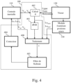
- FIG. 4 is an example of the system for resetting an inertial unit of a means of transport using information delivered by a viewfinder of the means of transport according to the present invention.
- the registration system comprises the inertial unit 110, the viewfinder 120, the landmark position supply module 130 and the registration device 100.
- the registration device 100 comprises a module 402 for calculating an angle ⁇ between the horizontal speed vector V and the line targeted in the horizontal plane Lv, a module 401 for calculating the derivative of the angle ⁇ , a processing module 400, a Kalman filter 403 and a correction module 404.
- the module 402 for calculating the angle ⁇ receives from the inertial unit 110 only the coordinates of the horizontal speed vector (V xg , V yg ) of the means of transport MT and the coordinates of the line of sight in the horizontal plane Lv. From the coordinates, the calculation module determines the angle ⁇ .
- the angle ⁇ is supplied to the calculation module 401 and to the processing module 400.
- the calculation module 401 determines the derivative ⁇ ' or d ⁇ /dt of the angle ⁇ and supplies this to the processing module 400.
- the inertial unit 110 provides the processing module 400 with the coordinates of the means of transport MT which are the altitude, the longitude Lo, the latitude La and the coordinates of the horizontal speed vector (V xg , V yg ) of the means of transport MT.
- the inertial unit 110 provides the viewfinder 120 with the orientation of the means of transport MT relative to the geographical marker in order to allow the positioning of the line of sight in the horizontal plane.
- the landmark position supply module 130 provides the processing module with the latitude La landmark and the longitude Lo landmark of the landmark targeted by the sight 120.
- the landmark position supply module 130 comprises a set of landmarks whose position is known and in a particular embodiment a set of so-called ephemeral landmarks whose position is determined by the landmark position supply module. as will be described with reference to the Fig. 6 .
- the processing module determines the error only if the derivative of the angle is non-zero.
- the error of the inertial unit 110 is introduced into the Kalman filter 403.
- the Kalman filter 403 is a classic filter which estimates the states of a dynamic system from a series of noisy measurements.
- the correction provided by the Kalman filter 403 is shaped by the correction module 404 to adapt the correction to the inertial unit and realign it.
- the derivative d ⁇ /dt is calculated by the calculation module 401 over a period of between 0.1 second for an airplane and 10 seconds for a ship.
- the present invention is particularly suitable for situations in which the means of transport MT is at a speed greater than 10 km/h and follows a trajectory having heading variations of +/- 20°.
- the present invention realigns the inertial unit 110 from the rotation speed of the means of transport MT measured around the vertical axis of the inertial unit 110 and the rotation speed of the horizontal line of sight measured around of the vertical axis by the gyroscopes of the viewfinder 120 or more generally by means integrated into the viewfinder 120.
- the angular value of the joint is for example determined as described in the patent FR3000219 .
- the present invention is also applicable when several Am landmarks are targeted by the viewfinder 120.
- the processing carried out by the processing module 100 is carried out successively for each landmark or the registration device is duplicated a predetermined number of times.
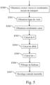
- FIG. 5 represents an example of an algorithm for realigning an inertial unit of a means of transport based on information delivered by a viewfinder of the means of transport according to the present invention.
- step E500 the registration device 100 of the inertial unit 110 obtains from the inertial unit a horizontal speed vector of the means of transport and the coordinates of the means of transport.
- step E501 the registration device 100 obtains the horizontal line of sight of the viewfinder 120 on at least one landmark.
- step E502 the registration device 100 obtains the coordinates of at least one landmark.
- step E503 the registration device 100 calculates an angle between the horizontal speed vector and the line of sight in the horizontal plane.
- step E504 the registration device 100 derives the calculated angle.
- step E505 the registration device 100 calculates the error from the coordinates obtained, the angle and its derivative calculated.
- step E506 the registration device 100 transfers the calculated error to the Kalman filter for filtering the error.
- step E507 the inertial unit 110 is reset.
- Fig. 6 represents an architecture of a module for providing landmark positions according to a particular embodiment of the present invention.
- the landmark position supply module 130 includes a database of known landmark positions 603 which is enriched from images delivered by the image capture device of the viewfinder 120.
- the landmark position supply module 130 comprises means 600 for detecting characteristic points PC in the images delivered by the image capture device of the viewfinder 120.
- the characteristic points PC i and j where i is the index of a first characteristic point and j the index of a second characteristic point, have unknown positions and speeds V i -V and V j -V with respect to the means of transport.
- the landmark position supply module 130 comprises means 601 for determining distances between the characteristic points PC.
- the landmark position supply module 130 includes means 602 for determining invariants in the characteristic points.
- the stability of the value of the coefficient ki,j, for a determined period is chosen as a criterion making it possible to determine whether the characteristic points PC i and j probably belong to the same family of points characteristics, that is to say probably belong to the same object in translation at the speed VV i relative to the means of transport MT.
- the means 602 for determining invariants in the characteristic points follow the variations of the coefficient k ij during voluntary variations in heading and/or speed resulting in the variation of the magnitude VV i .
- the means 602 for determining invariants form a set of characteristic points retaining the value of the coefficients k ij during course variations at constant speed and/or having variations in the square root of k ij inversely proportional to the norm of V.
- the landmark position supply module 130 comprises means 604 for correlating the positions of known landmarks stored in a database 603 of known landmarks with the set formed of characteristic points.
- the correlation means 604 identify the characteristic points of the formed set which have a position stored in the database 603.
- the landmark position supply module 130 comprises means 605 for determining positions of so-called ephemeral landmarks.
- the means 605 for determining positions of ephemeral landmarks determine, from the positions of the identified points, the positions of the other characteristic points of the set formed. These other characteristic points of the formed set are called ephemeral because they are likely to be deleted over time. These determined positions enrich the database 603.
Landscapes
- Engineering & Computer Science (AREA)
- Radar, Positioning & Navigation (AREA)
- Remote Sensing (AREA)
- Physics & Mathematics (AREA)
- General Physics & Mathematics (AREA)
- Automation & Control Theory (AREA)
- Manufacturing & Machinery (AREA)
- Navigation (AREA)
- Aiming, Guidance, Guns With A Light Source, Armor, Camouflage, And Targets (AREA)
- Image Analysis (AREA)
Description
- La présente invention concerne un procédé et un dispositif de recalage d'une centrale inertielle d'un moyen de transport à partir d'informations délivrées par un viseur du moyen de transport.
- Un moyen de transport, tel qu'un aéronef, un véhicule terrestre, un navire, utilise classiquement une centrale à inertie ou centrale inertielle pour la navigation. La centrale inertielle est capable d'intégrer les mouvements tels que l'accélération, la vitesse angulaire, du moyen de transport, pour estimer son orientation (angles de roulis, de tangage et de cap), sa vitesse linéaire et sa position. L'estimation de position est relative au point de départ ou au dernier point de recalage utilisé pour mettre à jour l'estimation de la position, de la vitesse et de l'attitude du moyen de transport.
- Une centrale de navigation inertielle comprend généralement un coeur inertiel et, optionnellement, une plateforme de support du coeur inertiel agencée pour maintenir le coeur inertiel dans un repère inertiel. Le coeur inertiel comprend des capteurs inertiels tels que des gyroscopes et des accéléromètres disposés selon les axes d'un repère de mesure. Après estimation d'un repère géographique pendant l'opération initiale d'alignement, les gyroscopes mesurent des rotations angulaires du repère de mesure par rapport au référentiel géographique et fournissent l'attitude du moyen de transport dans le référentiel géographique. Les accéléromètres mesurent des accélérations qui sont projetées dans le référentiel géographique, puis corrigées du champ gravitationnel terrestre, puis intégrées une première fois pour fournir la vitesse, puis une seconde fois pour fournir la position et mettre à jour le repère géographique. La précision d'une centrale inertielle dépend directement des erreurs des capteurs inertiels, et, dans le cas d'une navigation inertielle de longue durée, les erreurs de position dépendent de manière prépondérante de la précision des gyroscopes. La précision des gyroscopes est affectée par les erreurs de dérive, de facteurs d'échelle, et de calage d'axes.
- Il est alors nécessaire d'effectuer un recalage de la centrale inertielle.
- Le recalage d'une centrale inertielle est effectué pour corriger des erreurs qui s'accumulent au cours de la navigation du moyen de transport. Le recalage est effectué à partir d'une source d'informations externe qui procède à d'autres mesures que celles effectuées par la centrale inertielle et d'un système de filtrage tel que par exemple un filtre de Kalman.
- La demande de brevet
US 2015/253150 A1 divulgue un dispositif de recalage d'une centrale inertielle d'un moyen de transport à partir d'informations délivrées par un viseur du moyen de transport, le dispositif comportant : des moyens d'obtention de la centrale inertielle d'un vecteur vitesse horizontale du moyen de transport et de coordonnées du moyen de transport, des moyens d'obtention d'une ligne de visée horizontale du viseur sur au moins un amer, des moyens d'obtention de coordonnées dudit au moins un amer, des moyens de calcul d'un angle entre le vecteur vitesse horizontale et la ligne de visée horizontale, des moyens de calcul d'une erreur de la centrale inertielle à partir des coordonnées obtenues de l'angle. - Un objet de la présente invention est de proposer un procédé et un dispositif de recalage d'une centrale inertielle d'un moyen de transport à partir d'informations délivrées par un viseur du moyen de transport qui n'utilise pas de mesures de la distance entre le moyen de transport et un amer. Ceci permet ainsi d'éviter l'utilisation de moyens de type radar, s'appuyant en général sur une émission d'ondes électromagnétiques ou sonores, et donc d'être moins détectable par des moyens de détection d'ondes électromagnétiques ou sonores.
- A cet effet, la présente invention concerne un dispositif de recalage d'une centrale inertielle selon la revendication 1.
- L'invention concerne aussi un procédé de recalage d'une centrale inertielle selon la revendication 9.
- Ainsi, il est possible, sans avoir à connaître la distance séparant le moyen de transport d'au moins un amer, de recaler la centrale inertielle. Ceci permet ainsi de ne pas utiliser des instruments de télémétrie, en général peu discrets, pour recaler la centrale inertielle.
- Selon un mode particulier, la centrale inertielle fournit au viseur l'orientation du moyen de transport par rapport au repère géographique afin de permettre le positionnement de la ligne de visée dans le plan horizontal.
- Selon un mode particulier, l'erreur est calculée uniquement si la dérivée calculée est non nulle. Ainsi, la présente invention garantit que le recalage est effectué uniquement dans des conditions favorables.
- Selon un mode particulier, la dérivée est calculée sur une période de temps comprise entre 0.1 et 10 secondes.
- Ainsi, la précision du recalage est augmentée.
- Selon l'invention, l'erreur est calculée selon la formule suivante :

- L'invention concerne aussi un aéronef caractérisé en ce qu'il comporte le dispositif de recalage d'une centrale inertielle.
- L'invention concerne aussi un navire caractérisé en ce qu'il comporte le dispositif de recalage d'une centrale inertielle.
- L'invention concerne aussi un sous-marin caractérisé en ce qu'il comporte le dispositif de recalage d'une centrale inertielle.
- L'invention concerne aussi les programmes d'ordinateur stockés sur un support d'informations, lesdits programmes comportant des instructions permettant de mettre en oeuvre les procédés précédemment décrits, lorsqu'ils sont chargés et exécutés par un système informatique.
- Les caractéristiques de l'invention mentionnées ci-dessus, ainsi que d'autres, apparaîtront plus clairement à la lecture de la description suivante d'un exemple de réalisation, ladite description étant faite en relation avec les dessins joints, parmi lesquels :
- [
Fig. 1 ] représente un moyen de transport dans lequel la présente invention est implémentée ; - [
Fig.2 ] est un exemple d'une projection dans un plan horizontal d'une navigation d'un moyen de transport le long d'un parcours dans lequel sont placés des amers ; - [
Fig. 3 ] est un exemple d'informations obtenues à deux instants différents au cours du parcours du moyen de transport ; - [
Fig. 4 ] est un exemple du système de recalage d'une centrale inertielle d'un moyen de transport à partir d'informations délivrées par un viseur du moyen de transport selon la présente invention ; - [
Fig. 5 ] représente un exemple d'algorithme pour recaler une centrale inertielle d'un moyen de transport à partir d'informations délivrées par un viseur du moyen de transport selon la présente invention ; - [
Fig. 6 ] représente une architecture d'un module de fourniture de position d'amers selon un mode particulier de réalisation de la présente invention. - La
Fig. 1 représente un moyen de transport dans lequel la présente invention est implémentée. Le moyen de transport MT est par exemple un aéronef, un véhicule terrestre, un sous-marin ou un navire. - Le moyen de transport MT comporte une centrale inertielle 110, un viseur 120, un module de fourniture de positions d'amers 130 et un dispositif de recalage 100.
- La centrale inertielle 110 comprend des capteurs inertiels tels que des gyroscopes et des accéléromètres disposés selon les axes du repère de mesure. Les gyroscopes mesurent des rotations angulaires du repère de mesure par rapport à un référentiel géographique et fournissent l'attitude du moyen de transport MT dans le référentiel géographique. Les accéléromètres mesurent des accélérations qui sont projetées dans le référentiel géographique puis corrigées du champ gravitationnel terrestre, puis intégrées une première fois pour fournir la vitesse, puis une seconde fois pour fournir la position.
- La centrale inertielle 110, selon la présente invention, est recalée par un dispositif de recalage 100, entre autres, à partir d'un vecteur de visée d'un amer, ou ligne de visée horizontale, fournie par le viseur 120, à partir de la position de l'amer fournie par le module de fourniture de positions d'amers 130 et à partir du vecteur vitesse horizontale du moyen de transport MT mesuré par la centrale inertielle 110.
- Le viseur 120, ou tête de visée, est asservi sur la position d'au moins un amer. L'asservissement sur la position d'au moins un amer est réalisé à partir d'informations gyrométriques fournies par un trièdre gyrométrique solidaire de la ligne de visée. La ligne de visée est asservie sur une partie des images capturées par un dispositif de capture d'images non représenté en
Fig. 1 . - Dans le cas d'un sous-marin, le viseur 120 peut être un sonar passif qui fournit une représentation sous-marine et côtière des émissions sonores dans laquelle il est possible d'identifier des points d'émission particuliers, tenant le rôle des amers vus par le viseur optique d'un aéronef ou d'un navire.
- Selon un mode particulier de réalisation, le viseur est relié au module de fourniture de positions d'amers 130.
- La
Fig. 2 est un exemple d'une projection dans un plan horizontal d'une navigation d'un moyen de transport le long d'un parcours dans lequel sont placés des amers. - Le moyen de transport MT effectue un parcours Pr le long duquel sont disposés des amers Am1 à Am5 dont la position est connue et mémorisée dans le module de fourniture de positions d'amers 130. Lorsque un ou plusieurs amers sont à portée du moyen de transport, MT, la tête de visée pointe sur le ou les amers lorsque le moyen de transport est dans le périmètre de détection du ou des amers.
- Les amers Am1 à Am5 sont par exemple des phares côtiers pour la navigation maritime, des amers géographiques pour la navigation aérienne.
- Les périmètres de détection des amers Am1 à Am5 sont respectivement notés P1 à P5 en
Fig. 2 . - L'azimut, ou cap, est l'angle dans le plan horizontal entre la direction du moyen de transport MT et une direction de référence, par exemple le nord.
- Dans l'exemple de la
Fig. 2 , la tête de visée 120 pointe sur l'amer Am1 selon une ligne de visée projetée dans le plan horizontal Lv. - En
Fig. 2 , sont représentées la distance horizontale transverse dt orthogonale à la vitesse horizontale V entre le moyen de transport MT et l'amer Am1 et la distance horizontale longitudinale d1 selon la vitesse horizontale V entre le moyen de transport MT et l'amer Am1. Ces distances, selon la présente invention, ne sont pas connues. -
Fig. 3 est un exemple d'informations obtenues à deux différents instants t1 et t2 au cours du parcours du moyen de transport MT. - La distance parcourue selon d1 dans le plan longitudinal entre les instants t1 et t2 est notée 31 et est égale à V.Δt.
- La distance dt dans le plan horizontal perpendiculaire à V est notée 36 en
Fig. 3 et est égale à V.Δt.sinθ/tan Δθ où θ noté 30 enFig. 3 est l'angle entre le vecteur vitesse horizontale V du moyen de transport et la ligne de visée horizontale LvΔθ noté 35 enFig. 3 est la différence entre les angles θ déterminés aux instants t1 et t2. - La distance notée 32 en
Fig. 3 est égale à V.Δt.sinθ, la somme des distances notées 33 et 34 est la distance séparant le moyen de transport MT de l'amer Am1 à l'instant t1. - Si l'on considère que Δt est petit, par exemple égal à 1 seconde, la partie notée 34 en
Fig. 3 peut être considérée comme négligeable et il est possible de formuler dt et dl de la manière suivante :

- Ces équations permettent de définir un traitement utilisé selon la présente invention pour fournir une erreur à un filtre de navigation et recaler la centrale inertielle 110 comme cela est décrit par la suite en référence à la
Fig. 4 . - La
Fig. 4 est un exemple du système de recalage d'une centrale inertielle d'un moyen de transport à partir d'informations délivrées par un viseur du moyen de transport selon la présente invention. - Le système de recalage comporte la centrale inertielle 110, le viseur 120, le module de fourniture de positions d'amers 130 et le dispositif de recalage 100.
- Le dispositif de recalage 100 comporte un module 402 de calcul d'un angle θ entre le vecteur vitesse horizontale V et la ligne visée dans le plan horizontal Lv, un module 401 de calcul de la dérivée de l'angle θ, un module de traitement 400, un filtre de Kalman 403 et un module de correction 404.
- Le module 402 de calcul de l'angle θ reçoit de la centrale inertielle 110 uniquement les coordonnées du vecteur vitesse horizontale (Vxg, Vyg) du moyen de transport MT et les coordonnées de la ligne de visée dans le plan horizontal Lv. A partir des coordonnées, le module de calcul détermine l'angle θ.
- L'angle θ est fourni au module de calcul 401 et au module de traitement 400. Le module de calcul 401 détermine la dérivée θ' ou dθ/dt de l'angle θ et fournit celle-ci au module de traitement 400.
- La centrale inertielle 110 fournit au module de traitement 400 les coordonnées du moyen de transport MT que sont l'altitude, la longitude Lo, la latitude La et les coordonnées du vecteur vitesse horizontale (Vxg, Vyg) du moyen de transport MT.
- Selon un mode particulier, la centrale inertielle 110 fournit au viseur 120 l'orientation du moyen de transport MT par rapport au repère géographique afin de permettre le positionnement de la ligne de visée dans le plan horizontal.
- Le module de fourniture de positions d'amers 130 fournit au module de traitement la latitude Laamer et la longitude Loamer de l'amer visé par le viseur 120.
- Le module de fourniture de positions d'amers 130 comporte un ensemble d'amers dont la position est connue et dans un mode particulier de réalisation un ensemble d'amers dits éphémères dont la position est déterminée par le module de fourniture de positions d'amers comme cela sera décrit en référence à la
Fig. 6 . - Selon la présente invention, le module de traitement 400 détermine une erreur de la centrale inertielle à partir des différentes informations reçues selon la formule suivante :

- Plus particulièrement, le module de traitement détermine l'erreur uniquement si la dérivée de l'angle est non nulle.
- L'erreur de la centrale inertielle 110 est introduite dans le filtre de Kalman 403. Le filtre de Kalman 403 est un filtre classique qui estime les états d'un système dynamique à partir d'une série de mesures bruitées.
- La correction fournie par le filtre de Kalman 403 est mise en forme par le module de correction 404 pour adapter la correction à la centrale inertielle et la recaler.
- Il est à remarquer ici que la dérivée dθ/dt est calculée par le module de calcul 401 sur une durée comprise entre 0.1 seconde pour un avion et 10 secondes pour un navire.
- De plus, la présente invention est particulièrement adaptée aux situations dans lesquelles le moyen de transport MT est à une vitesse supérieure à 10 km/h et suit une trajectoire ayant des variations de cap de +/- 20°.
- Ainsi la présente invention effectue un recalage de la centrale inertielle 110 à partir de la vitesse de rotation du moyen de transport MT mesurée autour de l'axe vertical de la centrale inertielle 110 et de la vitesse de rotation de la ligne de visée horizontale mesurée autour de l'axe vertical par les gyroscopes du viseur 120 ou plus généralement par des moyens intégrés dans le viseur 120.
- S'il n'existe pas de moyens propres intégrés au viseur permettant le calcul de l'orientation de la ligne de visée dans le plan horizontal, par exemple lorsqu'une articulation existe entre la centrale inertielle 110 et le viseur 120, la valeur angulaire de l'articulation est par exemple déterminée comme cela est décrit dans le brevet
FR3000219 - La présente invention est aussi applicable lorsque plusieurs amers Am sont visés par le viseur 120. Par exemple, le traitement effectué par le module de traitement 100 est effectué successivement pour chaque amer ou le dispositif de recalage est dupliqué un nombre prédéterminé de fois.
- La
Fig. 5 représente un exemple d'algorithme pour recaler une centrale inertielle d'un moyen de transport à partir d'informations délivrées par un viseur du moyen de transport selon la présente invention. - A l'étape E500, le dispositif de recalage 100 de la centrale inertielle 110 obtient de la centrale inertielle un vecteur vitesse horizontale du moyen de transport et les coordonnées du moyen de transport.
- A l'étape E501, le dispositif de recalage 100 obtient la ligne de visée horizontale du viseur 120 sur au moins un amer.
- A l'étape E502, le dispositif de recalage 100 obtient les coordonnées d'au moins un amer. A l'étape E503, le dispositif de recalage 100 calcule un angle entre le vecteur vitesse horizontale et la ligne de visée dans le plan horizontal.
- A l'étape E504, le dispositif de recalage 100 dérive l'angle calculé.
- A l'étape E505, le dispositif de recalage 100 calcule l'erreur à partir des coordonnées obtenues, de l'angle et de sa dérivée calculés.
- A l'étape E506, le dispositif de recalage 100 transfère l'erreur calculée au filtre de Kalman pour un filtrage de l'erreur.
- A l'étape E507, la centrale inertielle 110 est recalée.
- La
Fig. 6 représente une architecture d'un module de fourniture de positions d'amers selon un mode particulier de réalisation de la présente invention. - Le module de fourniture de positions d'amers 130 comporte une base de données de positions d'amers connus 603 qui est enrichie à partir d'images délivrées par le dispositif de capture d'images du viseur 120.
- Le module de fourniture de positions d'amers 130 comporte des moyens 600 de détection de points caractéristiques PC dans les images délivrées par le dispositif de capture d'images du viseur 120. Les points caractéristiques PC i et j, où i est l'indice d'un premier point caractéristique et j l'indice d'un second point caractéristique, ont des positions et des vitesses Vi-V et Vj-V inconnues vis-à-vis du moyen de transport.
- Le module de fourniture de positions d'amers 130 comporte des moyens 601 de détermination de distances entre les points caractéristiques PC.
- En posant l'équation de la distance entre les deux de points caractéristiques PC i et j, notée Dij, dans laquelle θi est défini vis-à-vis du vecteur vitesse horizontale V-Vi et θj est défini vis-à-vis du vecteur vitesse horizontale V-Vj nous avons :

- Le module de fourniture de positions d'amers 130 comporte des moyens 602 de détermination d'invariants dans les points caractéristiques. Dans le cas où les points caractéristiques PC i et j ont la même vitesse vis-à-vis du moyen de transport MT, c'est-à-dire lorsque V-Vi=V-Vj, nous obtenons:


- Lorsque le moyen de transport MT est à vitesse constante, la stabilité de la valeur du coefficient ki,j, pendant une durée déterminée, est choisie comme critère permettant de déterminer si les points caractéristiques PC i et j appartiennent probablement à une même famille de points caractéristiques, c'est-à-dire appartiennent probablement à un même objet en translation à la vitesse V-Vi par rapport au moyen de transport MT.
- Les moyens 602 de détermination d'invariants dans les points caractéristiques suivent les variations du coefficient kij lors de variations volontaires de cap et/ou de vitesse ayant pour conséquence la variation de la grandeur V-Vi.
- Les moyens 602 de détermination d'invariants forment un ensemble de points caractéristiques conservant la valeur des coefficients kij lors des variations de cap à vitesse constante et/ou possédant des variations de la racine carré de kij inversement proportionnelles à la norme de V. Les points invariants correspondent à des points caractéristiques qui sont liés à la terre tels que des sommets de montagnes, des routes, des panneaux de signalisation, ou des éléments particuliers de la côte maritime. Sur cet ensemble de points, il est alors possible de calculer les distances entre chaque couple de points caractéristiques selon la formule suivante :

- Il est alors possible de créer une cartographie des points caractéristiques observés supposés liés à la terre vis-à-vis de la position du moyen de transport MT.
- Le module de fourniture de positions d'amers 130 comporte des moyens 604 de corrélation des positions des amers connus mémorisées dans une base de données 603 d'amers connus avec l'ensemble formé de points caractéristiques.
- Les moyens 604 de corrélation identifient les points caractéristiques de l'ensemble formé qui ont une position mémorisée dans la base de données 603.
- Le module de fourniture de positions d'amers 130 comporte des moyens 605 de détermination de positions d'amers dits éphémères. Les moyens 605 de détermination de positions d'amers éphémères déterminent, à partir des positions des points identifiés, les positions des autres points caractéristiques de l'ensemble formé. Ces autres points caractéristiques de l'ensemble formé sont appelés éphémères car ils sont susceptibles d'être supprimés dans le temps. Ces positions déterminées enrichissent la base de données 603.
Claims (9)
- Dispositif de recalage d'une centrale inertielle d'un moyen de transport à partir d'informations délivrées par un viseur du moyen de transport, le dispositif comportant :- des moyens d'obtention de la centrale inertielle (110) d'un vecteur vitesse horizontale du moyen de transport (MT) et de coordonnées du moyen de transport,- des moyens d'obtention d'une ligne de visée horizontale du viseur (120) sur au moins un amer,- des moyens d'obtention (130) de coordonnées dudit au moins un amer,- des moyens de calcul (402) d'un angle entre le vecteur vitesse horizontale et la ligne de visée horizontale,- des moyens de dérivation de l'angle calculé,- des moyens de calcul (400) d'une erreur de la centrale inertielle à partir des coordonnées obtenues, de l'angle et de sa dérivée calculés, l'erreur de la centrale inertielle étant calculée selon la formule suivante :
 - des moyens de transfert de l'erreur de la centrale inertielle calculée à un filtre de Kalman (403) pour un filtrage de l'erreur et un recalage de la centrale inertielle (110).
 - Dispositif selon la revendication 1, caractérisé en ce que l'erreur est calculée uniquement si la dérivée calculée est non nulle.
- Dispositif selon la revendication 2, caractérisé en ce que la dérivée est calculée sur une période de temps comprise entre 0.1 et 10 secondes.
- Dispositif selon l'une quelconque des revendications précédentes, caractérisé en ce que la centrale inertielle fournit au viseur l'orientation du moyen de transport par rapport au repère géographique pour le positionnement de la ligne de visée dans le plan horizontal.
- Dispositif selon l'une quelconque des revendications 1 à 4, caractérisé en ce que les coordonnées d'au moins un amer sont mémorisées dans une base de données mémorisant des positions d'amers connus et des positions d'amers déterminées à partir d'images délivrées par un dispositif de capture d'images du viseur.
- Aéronef caractérisé en ce qu'il comporte le dispositif de recalage d'une centrale inertielle selon l'une quelconque des revendications 1 à 4.
- Navire caractérisé en ce qu'il comporte le dispositif de recalage d'une centrale inertielle selon l'une quelconque des revendications 1 à 4.
- Sous-marin caractérisé en ce qu'il comporte le dispositif de recalage d'une centrale inertielle selon l'une quelconque des revendications 1 à 4.
- Procédé de recalage d'une centrale inertielle d'un moyen de transport à partir d'informations délivrées par un viseur du moyen de transport, le procédé comportant les étapes de :- obtention de la centrale inertielle d'un vecteur vitesse horizontale du moyen de transport et de coordonnées du moyen de transport,- obtention d'une ligne de visée horizontale du viseur sur au moins un amer,- obtention de coordonnées dudit au moins un amer,- calcul d'un angle entre le vecteur vitesse horizontale et la ligne de visée horizontale,- dérivation de l'angle calculé,- calcul d'une erreur de la centrale inertielle à partir des coordonnées obtenues, de l'angle et de sa dérivée calculés, , l'erreur de la centrale inertielle étant calculée selon la formule suivante :
 - transfert de l'erreur de la centrale inertielle calculée à un filtre de Kalman pour un filtrage de l'erreur et un recalage de la centrale inertielle.
Applications Claiming Priority (2)
| Application Number | Priority Date | Filing Date | Title |
|---|---|---|---|
| FR1905987A FR3097045B1 (fr) | 2019-06-06 | 2019-06-06 | Procédé et dispositif de recalage d’une centrale inertielle d’un moyen de transport à partir d’informations délivrées par un viseur du moyen de transport |
| PCT/EP2020/064366 WO2020244945A1 (fr) | 2019-06-06 | 2020-05-25 | Procede et dispositif de recalage d'une centrale inertielle d'un moyen de transport a partir d'informations delivrees par un viseur du moyen de transport |
Publications (2)
| Publication Number | Publication Date |
|---|---|
| EP3980720A1 EP3980720A1 (fr) | 2022-04-13 |
| EP3980720B1 true EP3980720B1 (fr) | 2023-12-20 |
Family
ID=68281575
Family Applications (1)
| Application Number | Title | Priority Date | Filing Date |
|---|---|---|---|
| EP20726483.9A Active EP3980720B1 (fr) | 2019-06-06 | 2020-05-25 | Procede et dispositif de recalage d'une centrale inertielle d'un moyen de transport a partir d'informations delivrees par un viseur du moyen de transport |
Country Status (6)
| Country | Link |
|---|---|
| US (1) | US11486708B2 (fr) |
| EP (1) | EP3980720B1 (fr) |
| CN (1) | CN113939712B (fr) |
| FR (1) | FR3097045B1 (fr) |
| WO (1) | WO2020244945A1 (fr) |
| ZA (1) | ZA202109974B (fr) |
Family Cites Families (26)
| Publication number | Priority date | Publication date | Assignee | Title |
|---|---|---|---|---|
| CN1153080C (zh) * | 1998-10-26 | 2004-06-09 | 米德仪器公司 | 分布式智能全自动望远镜系统 |
| IL149934A (en) * | 2002-05-30 | 2007-05-15 | Rafael Advanced Defense Sys | Airborne intelligence photography system |
| US7602415B2 (en) * | 2003-01-17 | 2009-10-13 | Insitu, Inc. | Compensation for overflight velocity when stabilizing an airborne camera |
| US7142981B2 (en) * | 2003-08-05 | 2006-11-28 | The Boeing Company | Laser range finder closed-loop pointing technology of relative navigation, attitude determination, pointing and tracking for spacecraft rendezvous |
| US7308342B2 (en) * | 2004-01-23 | 2007-12-11 | Rafael Armament Development Authority Ltd. | Airborne reconnaissance system |
| ATE552478T1 (de) * | 2004-06-03 | 2012-04-15 | Making Virtual Solid L L C | Navigationsanzeigeverfahren und vorrichtung für unterwegs unter verwendung eines head-up-displays |
| US8275544B1 (en) * | 2005-11-21 | 2012-09-25 | Miltec Missiles & Space | Magnetically stabilized forward observation platform |
| GB0604076D0 (en) * | 2006-03-01 | 2006-04-12 | Univ Lancaster | Method and apparatus for signal presentation |
| US9070101B2 (en) * | 2007-01-12 | 2015-06-30 | Fatdoor, Inc. | Peer-to-peer neighborhood delivery multi-copter and method |
| US8471906B2 (en) * | 2006-11-24 | 2013-06-25 | Trex Enterprises Corp | Miniature celestial direction detection system |
| RU2373498C2 (ru) * | 2007-10-08 | 2009-11-20 | Открытое Акционерное Общество "Конструкторское Бюро "Луч" | Навигационный комплекс, устройство вычисления скорости и координат, бесплатформенная инерциальная курсовертикаль, способ коррекции инерциальных датчиков и устройство для его осуществления |
| US8121618B2 (en) * | 2009-10-28 | 2012-02-21 | Digimarc Corporation | Intuitive computing methods and systems |
| KR101107219B1 (ko) * | 2010-01-05 | 2012-01-25 | 국방과학연구소 | 비행체의 항법 방법 및 이를 이용한 관성항법장치 필터 및 항법 시스템 |
| CA2792336C (fr) * | 2010-03-19 | 2018-07-24 | Digimarc Corporation | Procede et systeme pour le calcul informatise intuitif |
| US9372070B1 (en) * | 2012-07-17 | 2016-06-21 | L-3 Communications Corporation | Target locating device and methods |
| FR3000219B1 (fr) | 2012-12-26 | 2015-01-09 | Sagem Defense Securite | Procede de comparaison de deux centrales inertielles solidaires d'un meme porteur |
| FR3006437B1 (fr) * | 2013-06-03 | 2017-06-09 | Sagem Defense Securite | Procede de calibration autonome d'un equipement inertiel utilise en mode statique |
| FR3018383B1 (fr) * | 2014-03-07 | 2017-09-08 | Airbus Operations Sas | Procede et dispositif de determination de parametres de navigation d'un aeronef lors d'une phase d'atterrissage. |
| US10313656B2 (en) * | 2014-09-22 | 2019-06-04 | Samsung Electronics Company Ltd. | Image stitching for three-dimensional video |
| RU2614192C1 (ru) * | 2015-12-02 | 2017-03-23 | Акционерное общество "Раменское приборостроительное конструкторское бюро" | Способ оценивания ошибок инерциальной информации и её коррекции по измерениям доплеровского измерителя скорости |
| US10242581B2 (en) * | 2016-10-11 | 2019-03-26 | Insitu, Inc. | Method and apparatus for target relative guidance |
| CN106767900B (zh) * | 2016-11-23 | 2020-01-03 | 东南大学 | 一种基于组合导航技术的船用光纤捷联惯导系统的在线标定方法 |
| CN107270893B (zh) * | 2017-05-27 | 2020-11-06 | 东南大学 | 面向不动产测量的杆臂、时间不同步误差估计与补偿方法 |
| CN107806874B (zh) * | 2017-10-23 | 2019-01-15 | 西北工业大学 | 一种视觉辅助的捷联惯导极区初始对准方法 |
| CN108731670B (zh) * | 2018-05-18 | 2021-06-22 | 南京航空航天大学 | 基于量测模型优化的惯性/视觉里程计组合导航定位方法 |
| CN109029454A (zh) * | 2018-07-13 | 2018-12-18 | 哈尔滨工程大学 | 一种基于卡尔曼滤波的横坐标系捷联惯导系统阻尼算法 |
-
2019
- 2019-06-06 FR FR1905987A patent/FR3097045B1/fr active Active
-
2020
- 2020-05-25 EP EP20726483.9A patent/EP3980720B1/fr active Active
- 2020-05-25 US US17/614,232 patent/US11486708B2/en active Active
- 2020-05-25 WO PCT/EP2020/064366 patent/WO2020244945A1/fr active Application Filing
- 2020-05-25 CN CN202080040515.8A patent/CN113939712B/zh active Active
-
2021
- 2021-12-03 ZA ZA2021/09974A patent/ZA202109974B/en unknown
Also Published As
| Publication number | Publication date |
|---|---|
| EP3980720A1 (fr) | 2022-04-13 |
| ZA202109974B (en) | 2023-10-25 |
| FR3097045B1 (fr) | 2021-05-14 |
| CN113939712B (zh) | 2023-11-28 |
| CN113939712A (zh) | 2022-01-14 |
| US11486708B2 (en) | 2022-11-01 |
| FR3097045A1 (fr) | 2020-12-11 |
| US20220205790A1 (en) | 2022-06-30 |
| WO2020244945A1 (fr) | 2020-12-10 |
Similar Documents
| Publication | Publication Date | Title |
|---|---|---|
| US6768959B2 (en) | Apparatus and method for accurate pipeline surveying | |
| FR2667143A1 (fr) | Procede pour le mesurage d'angles, de trajectoires, de contours et d'anomalies de gravite au moyen de gyroscopes et de systemes inertiels. | |
| EP2932182B1 (fr) | Procede de geo localisation precise d'un capteur d'images embarque a bord d'un aeronef | |
| FR2694638A1 (fr) | Procédé et dispositif de compensation de mouvement d'images à ouverture synthétique au moyen d'un système de référence ligne de vol/position. | |
| EP2385346B1 (fr) | Procédé d'élaboration d'une phase de navigation dans un système de navigation impliquant une corrélation de terrain | |
| WO2010072917A1 (fr) | Procede de determination d'un cap en direction du nord geographique au moyen d'une centrale inertielle | |
| FR2971857A1 (fr) | Procede et systeme de determination des parametres de navigation d'un aeronef | |
| EP1828802B1 (fr) | Dispositif de determination autonome des coordonnees geographiques absolues d'un mobile evoluant en immersion | |
| EP1782098B1 (fr) | Procede de calibration angulaire d'une antenne par mesure de la distance relative | |
| JP2021518529A (ja) | 車両に装備されたジャイロメータの較正方法 | |
| CA2929198A1 (fr) | Procede de calcul de la vitesse surface d'au moins un navire et procede de deduction de chaque vecteur derive en tout point de la trajectoire dudit navire | |
| JPH0926328A (ja) | 位置標定装置 | |
| EP3980720B1 (fr) | Procede et dispositif de recalage d'une centrale inertielle d'un moyen de transport a partir d'informations delivrees par un viseur du moyen de transport | |
| FR3060178A1 (fr) | Dispositif electronique de pilotage d'un drone, drone, procede de pilotage et programme d'ordinateur associes | |
| EP3006897A1 (fr) | Procede de navigation d'un vehicule, dispositif de navigation et vehicule pour la mise en oeuvre de ce procede | |
| EP0881505B1 (fr) | Procédé de recalage de navigation d'un mobile au moyen d'une cartographie radar de zones de terrain à relief accentue | |
| EP0662602B1 (fr) | Procédé de navigation terrestre | |
| EP0389318B1 (fr) | Procédé d'aide à la navigation et navigateur terrestre perfectionné | |
| FR3109212A1 (fr) | Procede d’identification d’une phase statique d’un vehicule | |
| FR3041769A1 (fr) | Procede de geolocalisation | |
| FR3075354A1 (fr) | Procede de reperage d'un plan, dispositifs et procedes associes | |
| Shen | Nonlinear modeling of inertial errors by fast orthogonal search algorithm for low cost vehicular navigation | |
| WO2023083604A1 (fr) | Procédé d'estimation de la vitesse d'un véhicule ferroviaire et centrale inertielle associée | |
| WO2023083879A1 (fr) | Procede de navigation hybride inertielle/stellaire a indicateur de performance d'harmonisation | |
| WO2024089353A2 (fr) | Detection et correction de derive d'un dispositif de navigation par visee stellaire |
Legal Events
| Date | Code | Title | Description |
|---|---|---|---|
| STAA | Information on the status of an ep patent application or granted ep patent |
Free format text: STATUS: UNKNOWN |
|
| STAA | Information on the status of an ep patent application or granted ep patent |
Free format text: STATUS: THE INTERNATIONAL PUBLICATION HAS BEEN MADE |
|
| STAA | Information on the status of an ep patent application or granted ep patent |
Free format text: STATUS: THE INTERNATIONAL PUBLICATION HAS BEEN MADE |
|
| PUAI | Public reference made under article 153(3) epc to a published international application that has entered the european phase |
Free format text: ORIGINAL CODE: 0009012 |
|
| STAA | Information on the status of an ep patent application or granted ep patent |
Free format text: STATUS: REQUEST FOR EXAMINATION WAS MADE |
|
| 17P | Request for examination filed |
Effective date: 20211124 |
|
| AK | Designated contracting states |
Kind code of ref document: A1 Designated state(s): AL AT BE BG CH CY CZ DE DK EE ES FI FR GB GR HR HU IE IS IT LI LT LU LV MC MK MT NL NO PL PT RO RS SE SI SK SM TR |
|
| DAV | Request for validation of the european patent (deleted) | ||
| DAX | Request for extension of the european patent (deleted) | ||
| GRAP | Despatch of communication of intention to grant a patent |
Free format text: ORIGINAL CODE: EPIDOSNIGR1 |
|
| STAA | Information on the status of an ep patent application or granted ep patent |
Free format text: STATUS: GRANT OF PATENT IS INTENDED |
|
| INTG | Intention to grant announced |
Effective date: 20230220 |
|
| GRAJ | Information related to disapproval of communication of intention to grant by the applicant or resumption of examination proceedings by the epo deleted |
Free format text: ORIGINAL CODE: EPIDOSDIGR1 |
|
| STAA | Information on the status of an ep patent application or granted ep patent |
Free format text: STATUS: REQUEST FOR EXAMINATION WAS MADE |
|
| GRAP | Despatch of communication of intention to grant a patent |
Free format text: ORIGINAL CODE: EPIDOSNIGR1 |
|
| STAA | Information on the status of an ep patent application or granted ep patent |
Free format text: STATUS: GRANT OF PATENT IS INTENDED |
|
| INTC | Intention to grant announced (deleted) | ||
| INTG | Intention to grant announced |
Effective date: 20230710 |
|
| GRAS | Grant fee paid |
Free format text: ORIGINAL CODE: EPIDOSNIGR3 |
|
| GRAA | (expected) grant |
Free format text: ORIGINAL CODE: 0009210 |
|
| STAA | Information on the status of an ep patent application or granted ep patent |
Free format text: STATUS: THE PATENT HAS BEEN GRANTED |
|
| AK | Designated contracting states |
Kind code of ref document: B1 Designated state(s): AL AT BE BG CH CY CZ DE DK EE ES FI FR GB GR HR HU IE IS IT LI LT LU LV MC MK MT NL NO PL PT RO RS SE SI SK SM TR |
|
| REG | Reference to a national code |
Ref country code: GB Ref legal event code: FG4D Free format text: NOT ENGLISH |
|
| REG | Reference to a national code |
Ref country code: DE Ref legal event code: R096 Ref document number: 602020023065 Country of ref document: DE |
|
| REG | Reference to a national code |
Ref country code: CH Ref legal event code: EP |
|
| REG | Reference to a national code |
Ref country code: IE Ref legal event code: FG4D Free format text: LANGUAGE OF EP DOCUMENT: FRENCH |
|
| PG25 | Lapsed in a contracting state [announced via postgrant information from national office to epo] |
Ref country code: GR Free format text: LAPSE BECAUSE OF FAILURE TO SUBMIT A TRANSLATION OF THE DESCRIPTION OR TO PAY THE FEE WITHIN THE PRESCRIBED TIME-LIMIT Effective date: 20240321 |
|
| REG | Reference to a national code |
Ref country code: LT Ref legal event code: MG9D |
|
| PG25 | Lapsed in a contracting state [announced via postgrant information from national office to epo] |
Ref country code: LT Free format text: LAPSE BECAUSE OF FAILURE TO SUBMIT A TRANSLATION OF THE DESCRIPTION OR TO PAY THE FEE WITHIN THE PRESCRIBED TIME-LIMIT Effective date: 20231220 |
|
| REG | Reference to a national code |
Ref country code: NL Ref legal event code: MP Effective date: 20231220 |
|
| PG25 | Lapsed in a contracting state [announced via postgrant information from national office to epo] |
Ref country code: ES Free format text: LAPSE BECAUSE OF FAILURE TO SUBMIT A TRANSLATION OF THE DESCRIPTION OR TO PAY THE FEE WITHIN THE PRESCRIBED TIME-LIMIT Effective date: 20231220 |
|
| PG25 | Lapsed in a contracting state [announced via postgrant information from national office to epo] |
Ref country code: LT Free format text: LAPSE BECAUSE OF FAILURE TO SUBMIT A TRANSLATION OF THE DESCRIPTION OR TO PAY THE FEE WITHIN THE PRESCRIBED TIME-LIMIT Effective date: 20231220 Ref country code: GR Free format text: LAPSE BECAUSE OF FAILURE TO SUBMIT A TRANSLATION OF THE DESCRIPTION OR TO PAY THE FEE WITHIN THE PRESCRIBED TIME-LIMIT Effective date: 20240321 Ref country code: FI Free format text: LAPSE BECAUSE OF FAILURE TO SUBMIT A TRANSLATION OF THE DESCRIPTION OR TO PAY THE FEE WITHIN THE PRESCRIBED TIME-LIMIT Effective date: 20231220 Ref country code: ES Free format text: LAPSE BECAUSE OF FAILURE TO SUBMIT A TRANSLATION OF THE DESCRIPTION OR TO PAY THE FEE WITHIN THE PRESCRIBED TIME-LIMIT Effective date: 20231220 Ref country code: BG Free format text: LAPSE BECAUSE OF FAILURE TO SUBMIT A TRANSLATION OF THE DESCRIPTION OR TO PAY THE FEE WITHIN THE PRESCRIBED TIME-LIMIT Effective date: 20240320 |
|
| REG | Reference to a national code |
Ref country code: AT Ref legal event code: MK05 Ref document number: 1642813 Country of ref document: AT Kind code of ref document: T Effective date: 20231220 |
|
| PG25 | Lapsed in a contracting state [announced via postgrant information from national office to epo] |
Ref country code: NL Free format text: LAPSE BECAUSE OF FAILURE TO SUBMIT A TRANSLATION OF THE DESCRIPTION OR TO PAY THE FEE WITHIN THE PRESCRIBED TIME-LIMIT Effective date: 20231220 |