EP3980358B1 - Rejection mechanism for a conveyor system - Google Patents
Rejection mechanism for a conveyor system Download PDFInfo
- Publication number
- EP3980358B1 EP3980358B1 EP20815630.7A EP20815630A EP3980358B1 EP 3980358 B1 EP3980358 B1 EP 3980358B1 EP 20815630 A EP20815630 A EP 20815630A EP 3980358 B1 EP3980358 B1 EP 3980358B1
- Authority
- EP
- European Patent Office
- Prior art keywords
- paddle
- conveyor
- lateral wall
- wall portion
- rejection
- Prior art date
- Legal status (The legal status is an assumption and is not a legal conclusion. Google has not performed a legal analysis and makes no representation as to the accuracy of the status listed.)
- Active
Links
Images



Classifications
-
- B—PERFORMING OPERATIONS; TRANSPORTING
- B65—CONVEYING; PACKING; STORING; HANDLING THIN OR FILAMENTARY MATERIAL
- B65G—TRANSPORT OR STORAGE DEVICES, e.g. CONVEYORS FOR LOADING OR TIPPING, SHOP CONVEYOR SYSTEMS OR PNEUMATIC TUBE CONVEYORS
- B65G47/00—Article or material-handling devices associated with conveyors; Methods employing such devices
- B65G47/74—Feeding, transfer, or discharging devices of particular kinds or types
- B65G47/82—Rotary or reciprocating members for direct action on articles or materials, e.g. pushers, rakes, shovels
-
- B—PERFORMING OPERATIONS; TRANSPORTING
- B65—CONVEYING; PACKING; STORING; HANDLING THIN OR FILAMENTARY MATERIAL
- B65G—TRANSPORT OR STORAGE DEVICES, e.g. CONVEYORS FOR LOADING OR TIPPING, SHOP CONVEYOR SYSTEMS OR PNEUMATIC TUBE CONVEYORS
- B65G47/00—Article or material-handling devices associated with conveyors; Methods employing such devices
- B65G47/34—Devices for discharging articles or materials from conveyor
- B65G47/44—Arrangements or applications of hoppers or chutes
-
- B—PERFORMING OPERATIONS; TRANSPORTING
- B65—CONVEYING; PACKING; STORING; HANDLING THIN OR FILAMENTARY MATERIAL
- B65G—TRANSPORT OR STORAGE DEVICES, e.g. CONVEYORS FOR LOADING OR TIPPING, SHOP CONVEYOR SYSTEMS OR PNEUMATIC TUBE CONVEYORS
- B65G47/00—Article or material-handling devices associated with conveyors; Methods employing such devices
- B65G47/74—Feeding, transfer, or discharging devices of particular kinds or types
- B65G47/90—Devices for picking-up and depositing articles or materials
- B65G47/91—Devices for picking-up and depositing articles or materials incorporating pneumatic, e.g. suction, grippers
- B65G47/914—Devices for picking-up and depositing articles or materials incorporating pneumatic, e.g. suction, grippers provided with drive systems incorporating rotary and rectilinear movements
-
- B—PERFORMING OPERATIONS; TRANSPORTING
- B65—CONVEYING; PACKING; STORING; HANDLING THIN OR FILAMENTARY MATERIAL
- B65G—TRANSPORT OR STORAGE DEVICES, e.g. CONVEYORS FOR LOADING OR TIPPING, SHOP CONVEYOR SYSTEMS OR PNEUMATIC TUBE CONVEYORS
- B65G47/00—Article or material-handling devices associated with conveyors; Methods employing such devices
- B65G47/74—Feeding, transfer, or discharging devices of particular kinds or types
- B65G47/90—Devices for picking-up and depositing articles or materials
- B65G47/91—Devices for picking-up and depositing articles or materials incorporating pneumatic, e.g. suction, grippers
- B65G47/917—Devices for picking-up and depositing articles or materials incorporating pneumatic, e.g. suction, grippers control arrangements
-
- B—PERFORMING OPERATIONS; TRANSPORTING
- B65—CONVEYING; PACKING; STORING; HANDLING THIN OR FILAMENTARY MATERIAL
- B65G—TRANSPORT OR STORAGE DEVICES, e.g. CONVEYORS FOR LOADING OR TIPPING, SHOP CONVEYOR SYSTEMS OR PNEUMATIC TUBE CONVEYORS
- B65G2201/00—Indexing codes relating to handling devices, e.g. conveyors, characterised by the type of product or load being conveyed or handled
- B65G2201/02—Articles
- B65G2201/0285—Postal items, e.g. letters, parcels
Definitions
- the present invention relates to the handling of parcels within a sorting or similar facility.
- a sorting facility for parcels various parcels are unloaded from trucks or other vehicles at unloading locations, sorted, and then loaded onto trucks or other vehicles at loading locations for delivery to the intended recipients.
- trucks or other vehicles at unloading locations, sorted, and then loaded onto trucks or other vehicles at loading locations for delivery to the intended recipients.
- the first step is often to transform the bulk flow into a singulated flow of parcels in which the parcels are positioned at substantially equal intervals and aligned (i.e., in a single file line) along a conveyor for subsequent processing.
- singulators exist in the art, many of which employ various combinations of belt conveyors and/or roller conveyors to achieve the desired singulation of the parcels.
- a surge in the volume of parcels may overwhelm the mechanical systems, and parcels may not be fully singulated. Non-singulated parcels may then interfere with subsequent processing, including downstream sorting.
- U.S. Patent No. 10,646,898 thus describes a system and method for identifying and transferring parcels from a bulk flow on the first conveyor (or "pick conveyor") to a singulated stream of parcels on the second conveyor (or “place conveyor”).
- a robot singulator or robot receives parcels via the first conveyor, engages each parcel, and then places it onto the second conveyor.
- the robot singulator thus includes an end effector with a means for engaging the selected parcel.
- the end effector may include one or more vacuum cups for engaging the selected parcel.
- the end effector is mounted on a framework, which is controlled to move and position the end effector.
- the system also includes a vision and control subsystem associated with the robot.
- the vison and control subsystem includes one or more cameras that are operably connected to a computer for receiving and processing image data. Specifically, the one or more cameras are used to generate a three- dimensional representation of the parcels. Parcels are identified in the three-dimensional representation, and the computer then communicates instructions to position the robot such that the end effector can engage and manipulate each parcel.
- US9950878 discloses a case manipulator receives cases from an infeed conveyer and manipulates individual cases or groups of cases and transfers the manipulated cases to a row accumulator platform in a desired and pre-determined orientation and positioned on the accumulator platform to a desired and pre-determined location.
- the manipulation of individual cases, or groups of cases, is continued in a sequential operation until a complete row is formed on the accumulator platform according to a pre-determined build menu.
- the case manipulator includes a swing plate pivotal on a first axis and a paddle arm that is attached to the swing plate and pivotal on a second axis that is transverse to the first axis.
- US9950878 discloses a rejection mechanism according to the preamble of claim 1.
- certain parcels may exceed size and/or weight limitations or otherwise may be characterized as "unconveyable.”
- the vision and control subsystem may not be able to accurately identify a parcel because of a "hidden" edge or other anomaly that makes it difficult to identify the parcel.
- a rejection mechanism to handle those parcels that cannot be readily transferred from the first conveyor to the second conveyor.
- a rejection mechanism for a conveyor system generally includes a linear actuator and a paddle mounted to the linear actuator for movement between a first position and a second position.
- the paddle includes a lower bracket portion for mounting the paddle to the linear actuator, an upright portion that extends upward from the bracket portion, and a lateral wall portion that extends from the upright portion.
- the lateral wall portion of the paddle maintains a substantially horizontal orientation relative to the upright portion of the paddle as the paddle is moved from the first position to the second position.
- the rejection mechanism can thus be mounted relative to a target surface (or"rejection zone") of a conveyor, such that, as the linear actuator is actuated to move the paddle from the first position to the second position, the lateral wall portion of the paddle moves across the rejection zone. Parcels located in the rejection zone are thus pushed across the rejection zone and off of the conveyor by the lateral wall portion as the paddle is moved from the first position to the second position.
- the rejection mechanism further includes a way cover having a first end fixed in position and a second end that is mounted to the lateral wall portion of the paddle.
- the way cover expands and contracts with movement of the paddle, such that the way cover provides a trailing wall that fills in the space behind the lateral wall portion as the paddle moves from the first position to the second position.
- the way cover thus prevents parcels from falling behind the lateral wall portion of the paddle as the paddle is moved between the first position and the second position.
- the paddle further includes a brush mounted to the lateral wall portion of the paddle, which fills in any gap existing between the lateral wall portion of the paddle and an underlying surface, such as an upper surface of a conveyor, thereby ensuring smaller or flatter parcels are engaged by the paddle as it is moved from the first position to the second position.
- a brush mounted to the lateral wall portion of the paddle, which fills in any gap existing between the lateral wall portion of the paddle and an underlying surface, such as an upper surface of a conveyor, thereby ensuring smaller or flatter parcels are engaged by the paddle as it is moved from the first position to the second position.
- the lateral wall portion of the paddle is configured to transition between an engaged position and a disengaged position.
- the engaged position the lateral wall portion of the paddle is in a substantially horizontal orientation for engaging parcels in the rejection zone as the paddle is moved from the first position to the second position.
- the disengaged position the lateral wall portion is in a substantially vertical orientation, such that the paddle is able to move from the second position to the first position without moving over the rejection zone and engaging any parcels positioned thereon, thereby ensuring no parcels become trapped behind the lateral wall portion of the paddle.
- the upright portion of the paddle includes an upper section and a lower section connected by a hinge.
- the hinge defines an axis of rotation about which the lateral wall portion of the paddle can rotate to move between the engaged position and the disengaged position.
- the rejection mechanism further includes a first pushing mechanism, such as a linear actuator.
- the rejection mechanism further includes a second pushing mechanism, such as a linear actuator.
- the lateral wall portion of the paddle is operably connected to the upright portion of the paddle by a hinge.
- the hinge defines an axis of rotation about which the lateral wall portion of the paddle can rotate between the engaged position and the disengaged position.
- the first rejection mechanism further includes a first linkage that is operably connected the lateral wall portion of the paddle and mounted for sliding movement in a channel defined by a guide that is mounted to a surface of the upright portion of the paddle.
- a cam follower is mounted to and extends from the first linkage and is received within a track along which the cam follower moves as the linear actuator moves the paddle between the first position and the second position.
- the track may be defined by, and thus be characterized as including: an upper track portion; a lower track portion; a first inclined ramp interconnecting the upper track portion and the lower track portion; and a second inclined ramp that also interconnects the upper track portion and the lower track portion.
- the track is designed such that as the cam follower moves along the first inclined ramp, the lateral portion of the paddle is transitioned from the engaged position to the disengaged position, and, as the cam follower moves along the second inclined ramp, the lateral wall portion of the paddle is transitioned from the disengaged position to the engaged position.
- the rejection mechanism of the present invention can be combined with a conveyor for conveying a flow of parcels to provide an improved conveyor system for processing and sorting parcels.
- the conveyor system can further include a rejection chute, a robot singulator, an additional conveyor, and/or a control subsystem which regulates certain operations of one or more components of the conveyor system.
- the present invention is a rejection mechanism for a conveyor system, which pushes parcels across a surface, such as an upper surface of a conveyor.
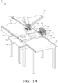
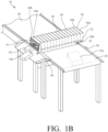
- FIGS. 1 A and IB are perspective views of a conveyor system 10 for conveying and transferring parcels 12a, 12b, 12c, which includes an exemplary rejection mechanism 50 made in accordance with the present invention.
- the conveyor system 10 further includes a first conveyor (or "pick conveyor") 20, a second conveyor (or “place conveyor') 30 downstream of the first conveyor 20, and a robot singulator (or robot) 35 for transferring parcels from the first conveyor 20 to the second conveyor 30.
- a first conveyor or "pick conveyor" 20
- second conveyor or "place conveyor'
- robot singulator or robot
- Parcels 12b, 12c which cannot be readily transferred by the robot singulator 35 end up in a rejection zone 20a (indicated in dashed lines in FIG. 1A ) near a leading edge 20b of the first conveyor 20.
- the rejection zone 20a corresponds with a portion of an upper surface of the first conveyor 20, which is in the path of a paddle 52 of the rejection mechanism 50, as further described below.
- parcels can also be accessed and engaged by the robot singulator 35 in the rejection zone 20a; in other words, parcels are not exclusively engaged by the rejection mechanism 50 in this area, as should become clear in the discussion that follows.
- the rejection mechanism 50 is selectively activated to push parcels 12b, 12c located in the rejection zone 20a off of the first conveyor 20 and onto a rejection chute 40 positioned to the side of the first conveyor 20 for subsequent sorting or recirculation back to the first conveyor 20.
- the rejection mechanism 50 is returned to its home position, and the first conveyor 20 is indexed forward to facilitate subsequent sorting of any remaining parcels located on the first conveyor 20.
- operation of the first conveyor 20, second conveyor 30, and/or the robot singulator 35 are, in at least some embodiments, regulated by a control subsystem 300.
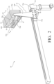
- FIG. 2 is a perspective view of the exemplary rejection mechanism 50, in isolation from the other components of the conveyor system 10 shown in FIGS. 1A and 1B .
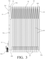
- FIG. 3 is a sectional view of the paddle of the exemplary rejection mechanism of FIG. 2 taken along line 3-3 of FIG. 2 .
- the rejection mechanism 50 includes a paddle 52 that is mounted on a linear actuator 54, such that the paddle 52 can be moved between a first (or home) position, as shown in FIG. 1A , and a second position, as shown in FIG. 1B , via the linear actuator 54.
- the linear actuator 54 is a motor-controlled actuator, with a carriage 54a that moves between the first position and the second position.
- suitable linear actuators are commercially available. For example, one suitable linear actuator for this purpose is manufactured and distributed by Schneider Electric USA of Andover, Massachusetts, Model. No. PAS42BB.
- the linear actuator 54 may be a rod-less pneumatic actuator, such as that manufactured and distributed by Festo Corporation of Hauppauge, New York, Model No. DGC-32-1200-KF-YSRW-A ZUB-F-M.
- operation of the linear actuator 54 i.e., movement of the carriage 54a
- the paddle 52 has a unitary construction.
- the paddle includes: a lower bracket portion 52a; an upright portion 52b that extends from the lower bracket portion 52a; and a lateral wall portion 52c that extends from the upright portion 52b.
- the lateral wall portion 52c extends horizontally from the upright portion 52b and is in a perpendicular orientation relative to the upright portion 52b of the paddle 52.
- the lower bracket portion 52a is mounted to the carriage 54a of the linear actuator 54 by one or more fasteners 56, such as bolts or similar conventional fasteners.
- the rejection mechanism 50 is positioned relative to the first conveyor 20, such that, as the paddle 52 moves from the first position to the second position, the paddle 52 moves across the rejection zone 20a toward the rejection chute 40.
- the movement of the lateral wall portion 52c of the paddle 52 across the rejection zone 20a thus pushes any parcels 12b, 12c located in the rejection zone 20a off of the first conveyor 20 and onto the rejection chute 40.
- the linear actuator 54 of the rejection mechanism 50 can thus be selectively activated to discharge parcels 12b, 12c from the first conveyor 20.
- the linear actuator 54 in this embodiment, is mounted below the leading edge 20b of the first conveyor 20, such that the upright portion 52b of the paddle 52 extends upward and adjacent to the leading edge 20b of the first conveyor 20, and the lateral wall portion 52c of the paddle 52 is thus positioned over the upper surface of the first conveyor 20.
- the second conveyor 30 is positioned downstream of and adjacent to the first conveyor 20, such that the upright portion 52b of the paddle 52 extends upward through a gap between the first conveyor 20 and the second conveyor 30.
- the linear actuator 54 may alternatively be mounted to the second conveyor 30 and still enable the exemplary rejection mechanism 50 to function in the manner described herein.
- this vertical gap may be approximately 10mm.
- the paddle 52 includes a brush 52d mounted to the front face of the lateral wall portion 52c, such that the bristles of the brush 52d extend below the bottom edge of the lateral wall portion 52c to engage the upper surface of the first conveyor 20.
- the brush 52d thus substantially eliminates the gap existing between the lateral wall portion 52c and the upper surface of the first conveyor 20.
- the brush 52d provides a sweeping force across the upper surface of the first conveyor 20, which ensures that smaller parcels 12a, 12b, 12c, such as flat mailers, are engaged by the paddle 52 and do not pass under the lateral wall portion 52c of the paddle 52.
- the brush 52d is removably mounted to the lateral wall portion 52c by one or more fasteners 57, such as bolts or similar conventional fasteners.
- the components of the paddle 52 are constructed of steel or another suitable metal to prevent or limit the extent to which the paddle 52 is deformed or broken down as a result of repeated trips across the rejection zone 20a and engagement with parcels 12a, 12b, 12c located thereon.
- a plurality of openings 52e are defined by, and thus can be characterized as being present within, the lateral wall portion 52c. Such openings 52e reduce the overall weight of the lateral wall portion 52c.
- the rejection mechanism 50 further includes a way cover 60.
- the way cover 60 has a first end 60a fixed in position relative to the conveyor system 10 and a second end 60b mounted to the lateral wall portion 52c of the paddle 52.
- the first end 60a of the way cover 60 is mounted to a bracket 22 mounted to the first conveyor 20 by one or more fasteners (not shown), such as bolts or similar conventional fasteners
- the second end 60b of the way cover 60 is mounted to a rear face of the lateral wall portion 52c of the paddle 52 by one or more fasteners 55, such as bolts or similar conventional fasteners.
- the way cover 60 is configured to expand and contract with movement of the paddle 52.
- the way cover 60 gradually expands from a contracted configuration (as shown in FIG. 1A ) to an expanded configuration (as shown in FIG. 1B ).
- the way cover 60 is designed and configured such that, upon the paddle 52 reaching the second position ( FIG. 1B ), the way cover 60 is fully expanded, resulting in a substantially flat upper surface of the way cover 60.
- the way cover 60 thus provides a trailing wall behind the lateral wall portion 52c of the paddle 52, which fill in the space behind the lateral wall portion 52c of the paddle 52 as the paddle 52 moves from the first position to the second positon, thereby preventing any parcels located on the first conveyor 20 from falling behind the lateral wall portion 52c of the paddle 52 as the paddle 52 moves between the first position and the second position.
- the way cover 60 prevents parcels from becoming trapped behind the lateral wall portion 52c of the paddle 52 during operation of the rejection mechanism 50.
- a parcel could flip over the lateral wall portion 52c of the paddle 52 as the paddle 52 moves from the first position and the second position, which could hinder or prevent the paddle 52 from returning back to the first position.
- the conveyor system 10 may include a wall surface positioned above the way cover 60, which would push any parcels 12a, 12b, 12c having fallen on top of the way cover 60 off of the way cover 60 as the paddle 52 is returned by the linear actuator 54 to the first position.
- any parcels flip over the lateral wall portion 52c of the paddle 52 and onto the upper surface of the way cover 60, they would be pushed off the upper surface of the way cover 60 as the paddle 52 returns back to the first position.
- FIG. 4 is an enlarged front view of the way cover 60 in isolation.
- the way cover 60 is comprised of a first face plate 62, a second face plate 64, a cover 66, and a plurality of stiffeners 68.
- the first face plate 62 which is at the second end 60b of the way cover 60, is mounted to the lateral wall portion 52c of the paddle 52.
- the first face plate 62 defines a plurality of openings 63 corresponding to a plurality of openings defined by the lateral wall portion 52c, so that the first face plate 62 can be mounted to the lateral wall portion 52c via one or more fasteners 55, such as bolts or similar conventional fasteners.
- the first face plate 62 can be characterized as including three sections: a first side section 62a; a second side section 62b; and a top section 62c extending between the first and second side sections 62a, 62b. Furthermore, in this exemplary embodiment, the width and the height of the first face plate 62 substantially corresponds to that of the lateral wall portion 52c of the paddle 52.
- the second face plate 64 is mounted to a component of the conveyor system 10 to hold the first end 60a of the way cover 60 in a fixed position as the paddle 52 moves the first face plate 62, and thus the second end 60b of the way cover 60, across the rejection zone 20a.
- the second face plate 64 is mounted to the bracket 22, which is shown in FIGS. 1A and 1B .
- the shape of the second face plate 64 preferably corresponds to that of the first face plate 62, and thus, in this exemplary embodiment, the lateral wall portion 52c of the paddle 52.
- the second face plate 64 thus also defines a plurality of openings corresponding to a plurality of openings defined by the bracket 22, so that the second face plate 64 can be mounted to the bracket 22 via one or more fasteners (not shown), such as bolts or similar conventional fasteners
- the opposing ends 66a, 66b of the cover 66 are mounted to the first face plate 62 and the second face plate 64, and the cover 66 is comprised of a flexible fabric or similar material that can readily expand or contract as the paddle 52 is moved between the first position and the second position.
- Multiple stiffeners 68 are positioned along the length of the cover 66 between the opposing ends 66a, 66b of the cover 66, and these stiffeners 68 are mounted to and enclosed by the cover 66.
- the stiffeners 68 maintain the shape of the trailing wall established by the way cover 60 as the paddle 52 moves between the first position and the second position.
- each stiffener 68 is constructed of a metal plate having a shape corresponding to that of the first face plate 62 and the lateral wall portion 52c of the paddle 52. Accordingly, like the first face plate 62, each stiffener 68 can be characterized as including three sections: a first side section; a second side section; and a top section extending between the first and second side sections.
- the cover 66 extends along and fully covers the first side section, the second side section, and the top section of each stiffener 68.
- the cover 66 establishes a three-sided wall (two side walls and a top wall), which expands and contracts with movement of the paddle 52.
- the flexible material of the cover 66 is configured to fold in an accordion-like manner as the paddle 52 is moved from the second position to the first position and the way cover 60 contracts.
- the way cover 60 may also be referred to as a "bellows.”
- each stiffener 68 includes a tip 69 on at least one of its sides. Specifically, in this exemplary embodiment, each side (only one of which is shown in FIG. 3 ) of each stiffener 68 terminates at a tip 69. Each tip 69 is configured to engage and move along an upper surface of the first conveyor 20 as the paddle 52 moves across the rejection zone 20a. In this exemplary embodiment, the lowermost portion of each tip 69 and the lowermost portion of the brush 52d reside in substantially the same plane.
- each tip 69 maintain the lateral wall portion 52c of the paddle 52 in a generally parallel orientation relative to the upper surface of the first conveyor 20 and reduce the strain imposed on the upright portion 52b caused by the weight of the lateral wall portion 52c.
- each tip 69 is preferably constructed from a material with a low coefficient of friction and high durability, such as an ultra-high molecular weight polyethylene (UHMW).
- UHMW ultra-high molecular weight polyethylene
- the way cover 60 may further include a plurality of lamellas (or plates) provided along each wall of the cover 66.
- each lamella would be mounted to a respective wall of the cover 66, such that the lamellas effectively stack upon each other as the way cover 60 contracts.
- the lamellas effectively cover the"valleys" resulting from the cover 66 being folded into an accordion-like construction, thereby preventing parcels 12a, 12b, 12c from becoming caught or trapped in the way cover 60 as it is contracted.
- the way cover may be constructed as to transition between a rolled-up configuration and an extended (or unrolled) configuration.
- the way cover would have a first end fixed in position relative to the conveyor system and a second end mounted to the lateral wall portion of the paddle.
- the way cover would not include any of the plates 62, 64 or stiffeners 68 described above with reference to FIGS. 3-4 .
- the way cover would include a single length of material that is rolled onto a rod, much like a roll-up window shade. When the paddle 52 is in the first position, the material would be stored on the rod in the rolled- up configuration.
- the rod would rotate, and the material would unfurl from the rod until the way cover is in the extended (or unrolled) configuration.
- the way cover would again provide a wall extending across the rejection zone 20a of the first conveyor 20.
- FIGS. 5 A and 5B are perspective views of another conveyor system 100 for conveying and transferring parcels 12a, 12b, 12c, which includes another exemplary rejection mechanism 150 falling outside the literal scope of Claim 1.
- the conveyor system 100 includes each of the components (i.e., the first conveyor 20, the second conveyor 30, robot singulator 35, and rejection chute 40) of the conveyor system 10 illustrated and described above with reference to FIGS. 1 A and IB , where each respective component includes the same features and provides the same functionality as described above.
- the rejection mechanism 150 is selectively activated to push parcels 12b, 12c located in the rejection zone 20a off of the first conveyor 20 and onto a rejection chute 40 positioned to the side of the first conveyor 20 for subsequent sorting or recirculation back to the first conveyor 20.
- the rejection mechanism 150 can be returned to its home position, and the first conveyor 20 is indexed forward to facilitate subsequent sorting of any remaining parcels located on the first conveyor 20.
- movement of the first conveyor 20, second conveyor 30, and/or the robot singulator 35 are, in at least some embodiments, regulated by a control subsystem 400.
- FIG. 6 is a perspective view of the exemplary rejection mechanism 150, in isolation from the other components of the conveyor system 100 shown in FIGS. 5A and 5B .
- the rejection mechanism 150 includes a paddle 152 that is mounted on a linear actuator 154, such that the paddle 152 can be moved between a first (or home) position, as shown in FIG. 5 A , and a second position, as shown in FIG. 5B , via the linear actuator 154.
- the linear actuator 154 is a motor-controlled actuator, with a carriage 154a that moves between the first position and the second position.
- suitable linear actuators are commercially available.
- one suitable linear actuator for this purpose is manufactured and distributed by Schneider Electric USA of Andover, Massachusetts, Model. No. PAS42BB.
- the linear actuator 154 may be a rod-less pneumatic actuator, such as that manufactured and distributed by Festo Corporation of Hauppauge, New York, Model No. DGC- 32-1200-KF-YSRW-A ZUB-F-M.
- operation of the linear actuator 154 i.e., movement of the carriage 154a
- the paddle 152 includes: a lower bracket portion 152a; an upright portion 152b that extends from the lower bracket portion 152a; and a lateral wall portion 152c that extends from the upright portion 152b.
- the respective components of the paddle 152 may be constructed from the same materials as those of the paddle 52 of the rejection mechanism 50 described above with reference to FIGS.1A , IB, and 2.
- the lateral wall portion 152c of the paddle 152 may also define a plurality of openings for weight reduction, like the rejection mechanism 50 described above with reference to FIGS. 1A , IB, and 2.
- the lower bracket portion 152a is mounted to the carriage 154a of the linear actuator by one or more fasteners 156, such as bolts or similar conventional fasteners.
- the upright portion 152b of the paddle 152 includes an upper section 153a and a lower section 153b connected together by a hinge 153c.
- the lateral wall portion 152c is operably connected to and extends from the upper section 153a of the upright portion 152b, while the lower section 153b of the upright portion 152b is operably connected to the lower bracket portion 152a of the paddle 152.
- the lower section 153b of the upright portion 152b and the lower bracket portion 152a are formed from a single piece of material, i.e., have a unitary construction.
- the upper section 153a of the upright portion 152b can thus effectively rotate about an axis of rotation defined by the hinge 153c to transition the lateral wall portion 152c of the paddle 152 between: (i) an engaged position, in which the lateral wall portion 152c of the paddle is in a substantially horizontal orientation (i.e., extends perpendicular relative to the lower section 153b of the upright portion 152b); and (ii) a disengaged position, in which the lateral wall portion 152c of the paddle is in a substantially vertical orientation (i.e., extends vertically relative to the lower section 153b of the upright portion 152b).
- the paddle 152 also includes a stop 153d mounted to the lower section 153b of the upright portion 152b, which prevents rotation of the upper section 153a of the upright portion 152b beyond a predefined limit when the lateral wall portion 152c of the paddle 152 is transitioned to a disengaged position.
- the rejection mechanism 150 is positioned relative to the first conveyor 20, such that, as the paddle 152 moves from the first position to the second position while the lateral wall portion 152c is in the engaged position, the paddle 152 moves across the rejection zone 20a toward the rejection chute 40.
- the movement of the lateral wall portion 152c of the paddle 152 across the rejection zone 20a, while in the engaged position, thus pushes any parcels 12b, 12c located in the rejection zone 20a off of the first conveyor 20 and onto the rejection chute 40.
- the linear actuator 154 of the rejection mechanism 150 can thus be selectively activated while the lateral wall portion 152c is in the engaged position to discharge parcels 12b, 12c from the first conveyor 20.
- the linear actuator 154 (only a portion of which is shown in FIGS. 5A and 5B ) is mounted below the leading edge 20b of the first conveyor 20, such that both the upper section 153a and the lower section 153b of the upright portion 152b of the paddle 152 extend upward and adjacent to the leading edge 20b of the first conveyor 20 when the lateral wall portion 152c is in the engaged position.
- the second conveyor 30 is positioned downstream of and adjacent to the first conveyor 20, such that the upright portion 152b of the paddle 152 extends upward through a gap between the first conveyor 20 and the second conveyor 30.
- the linear actuator 154 may alternatively be mounted to the second conveyor 30 and still enable the exemplary rejection mechanism 150 to function in the manner described herein.
- this vertical gap may be approximately 10mm.
- the lateral wall portion 152c of the paddle 152 can be rotated from the engaged position to the disengaged position about the hinge 153c. Accordingly, when the linear actuator 154 returns the paddle 152 from the second position to the first position, the lateral wall portion 152c of the paddle 152 does not pass back over the rejection zone 20a. Rather, the lateral wall portion 152c is in a substantially vertical orientation during its return to the first position.
- the conveyor system 100 further includes a first pushing mechanism 160 and a second pushing mechanism 162.
- the first pushing mechanism 160 is a motor-controlled linear actuator, which includes an arm 160a that can be extended to engage the lateral wall portion 152c of the paddle 152, rotating it about the hinge 153c from the disengaged position to the engaged position.
- the first pushing mechanism 160 is a motor-controlled linear actuator, which includes an arm 160a that can be extended to engage the lateral wall portion 152c of the paddle 152, rotating it about the hinge 153c from the disengaged position to the engaged position.
- the second pushing mechanism 162 is a motor-controlled linear actuator, which includes an arm 162a that can be extended to engage the lateral wall portion 152c of the paddle 152, rotating it about the hinge 153c from the engaged position to the disengaged position.
- a motor-controlled linear actuator which includes an arm 162a that can be extended to engage the lateral wall portion 152c of the paddle 152, rotating it about the hinge 153c from the engaged position to the disengaged position.
- many different types of linear actuators or other similar mechanisms may provide the desired rotation (or flipping) of the lateral wall portion 152c of the paddle 152 between the engaged position and the disengaged position.
- the first pushing mechanism 160 is mounted such that the arm 160a of the first pushing mechanism 160 can be extended in a substantially horizontal direction to engage the lateral wall portion 152c of the paddle 152 when the paddle 152 is in the first position.
- the lateral wall portion 152c rotates about the axis of rotation defined by the hinge 153c from the disengaged position to the engaged position.
- the first pushing mechanism 160 flips the lateral wall portion 152c from the disengaged position to the engaged position.
- the first pushing mechanism 160 is mounted to the second conveyor 30 by a bracket 32.
- the first pushing mechanism 160 may be mounted in any suitable orientation which permits the arm 160a to extend and engage the lateral wall portion 152c of the paddle 152 in the manner described above.
- the second pushing mechanism 162 is mounted such that the arm 162a of the second pushing mechanism 162 can be extended in a substantially vertical direction to engage the lateral wall portion 152c of the paddle 152 when the paddle 152 is in the second position.
- the lateral wall portion 152c rotates about the axis of rotation defined by the hinge 153c from the engaged position to the disengaged position.
- the second pushing mechanism 162 flips the lateral wall portion 152c from the engaged position to the disengaged position.
- the second pushing mechanism 162 is mounted to the first conveyor 20 below the rejection chute 40.
- the rejection chute 40 defines an opening 40a through which the arm 162a of the second pushing mechanism 162 can extend to engage the lateral wall portion 152c of the paddle 152.
- the second pushing mechanism 162 may be mounted in any suitable orientation which permits the arm 162a of the second pushing mechanism 162 to extend and engage the lateral wall portion 152c of the paddle 152 in the manner described above.
- operation of the linear actuator 154, the first pushing mechanism 160, and/or the second pushing mechanism 162 are, in at least some embodiments, regulated by a control subsystem 400.
- FIGS. 7 A and 7B are perspective views of another conveyor system 200 for conveying and transferring parcels 12a, 12b, 12c, which includes another exemplary rejection mechanism 250 outside the literal scope of Claim 1.
- the conveyor system 200 includes each of the components (i.e., the first conveyor 20, the second conveyor 30, robot singulator 35, and rejection chute 40) of the conveyor system 10 illustrated and described above with reference to FIGS. 1 A and IB , where each respective component includes the same features and provides the same functionality as described above.
- the exemplary rejection mechanism 250 is selectively activated to push parcels 12b, 12c located in the rejection zone 20a off of the first conveyor 20 and onto a rejection chute 40 positioned to the side of the first conveyor 20 for subsequent sorting or recirculation back to the first conveyor 20.
- the rejection mechanism 250 can be returned to its home position, and the first conveyor 20 is indexed forward to facilitate subsequent sorting of any remaining parcels located on the first conveyor 20.
- operation of the first conveyor 20, second conveyor 30, and/or the robot singulator 35 are, in at least some embodiments, regulated by a control subsystem 300.
- FIG. 8 is a perspective view of the exemplary rejection mechanism 250, in isolation from the other components of the conveyor system 200 shown in FIGS. 7 A and 7B .
- the rejection mechanism 250 includes a paddle 252 that is mounted on a linear actuator 254, such that the paddle 252 can be moved between a first (or home) position, as shown in FIG. 7A , and a second position, as shown in FIG. 7B , via the linear actuator 254.
- the linear actuator 254 is a motor-controlled actuator, with a carriage 254a that moves between the first position and the second position.
- suitable linear actuators are commercially available. For example, one suitable linear actuator for this purpose is manufactured and distributed by Schneider Electric USA of Andover, Massachusetts, Model. No. PAS42BB.
- the linear actuator 254 may be a rod-less pneumatic actuator, such as that manufactured and distributed by Festo Corporation of Hauppauge, New York, Model No. DGC-32-1200-KF-YSRW-A ZUB-F-M.
- operation of the linear actuator 254 i.e., movement of the carriage 254a
- a control subsystem 300 i.e., movement of the carriage 254a
- the paddle 252 includes: a lower bracket portion 252a; an upright portion 252b that extends from the lower bracket portion 252a; and a lateral wall portion 252c that extends from the upright portion 252b.
- the respective components of the paddle 252 may be constructed from the same materials as those of the paddles 52, 152 of the rejection mechanisms 50, 150 described above.
- the lateral wall portion 252c of the paddle 252 may also define a plurality of openings for weight reduction, like the rejection mechanisms 50, 150 described above.
- the lower bracket portion 252a is mounted to the carriage 254a of the linear actuator by one or more fasteners 256, such as bolts or similar conventional fasteners.
- the lower bracket portion 252a and the upright portion 252b are formed from a single piece of material, i.e., have a unitary construction.
- the lateral wall portion 252c is connected to the upright portion 252b by a hinge 253a.
- the lateral wall portion 252c is able to rotate about an axis of rotation defined by the hinge 253a between: (i) an engaged position, in which the lateral wall portion 252c of the paddle 252 is in a substantially horizontal orientation (i.e., extends perpendicular relative to the upright portion 252b of the of the paddle 252); and (ii) a disengaged position, in which the lateral wall portion 252c is in a substantially vertical orientation (i.e., extends vertically relative to the upright portion 252b of the paddle).
- the upright portion 252b defines a slit 252d in which the lateral wall portion 252c can travel through and rest within, as further described below.
- a first linkage 253b (or “linear slide") is mounted for sliding movement in a channel defined by a guide 253c, which, is mounted to a surface of the upright portion 252b of the paddle 252.
- a distal end of the first linkage 253b is operably connected to the lateral wall portion 252c of the paddle 252, such that the first linkage 253b can be manipulated to slide the first linkage 253b within the guide 253c and move the lateral wall portion 252c between the engaged and disengaged position.
- a distal end of the first linkage 253b is pivotally connected to a proximal end of a second linkage 253d (or “connector linkage”), preferably via a pin connection.
- a distal end of the second linkage 253d is then pivotally connected to the lateral wall portion 252c of the paddle 252.
- a cam follower 253e is mounted for rotation with respect to, and extends from, the first linkage 253b to control movement of the first linkage 253b within the guide 253c, as further described below.
- the linear actuator 254 (only a portion of which is shown in FIGS. 7A and 7B ) is mounted below the leading edge 20b of the first conveyor 20, such that the upright portion 252b of the paddle 252 extends upward and adjacent to the leading edge 20b of the first conveyor 20.
- the second conveyor 30 is positioned downstream and adjacent to the first conveyor 20, such that the upright portion 252b of the paddle 252 extends upward through a gap between the first conveyor 20 and the second conveyor 30.
- the linear actuator 254 may alternatively be mounted to the second conveyor 30 and still enable the exemplary rejection mechanism 250 to function in the manner described herein.
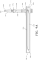
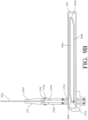
- FIGS. 9A and 9B are various side views of the paddle 252 at different positions along a track.
- the cam follower 253e is positioned within a track 260 (or “linear cam"), such that, as the linear actuator 254 moves the paddle 252 between the first position ( FIG. 7A ) and the second position ( FIG. 7B ), the cam follower 253e is moved along the track 260 to transition the lateral wall portion 252c of the paddle between the engaged and disengaged position, as further described below.
- the track 260 is mounted below the leading edge of the first conveyor 20.
- the track 260 may alternatively be mounted to the second conveyor 30 and still enable the exemplary rejection mechanism 250 to function in the manner described herein.
- the track 260 is defined by, and can be characterized as including: an upper track portion 260a; a lower track portion 260b; a first inclined ramp 260c, which interconnects the upper track portion 260a and the lower track portion 260b; and a second inclined ramp 260d, which also interconnects the upper track portion 260a and the lower track portion 260b.
- the track 260 is a closed loop.
- the cam follower 253e is correspondingly moved from a first portion of the track 260 ( FIG. 9A ), which, in this embodiment, is an upper-right portion of the track 260, to a second portion of the track 260, which, in this embodiment, is lower-left portion of the track 260.
- the lateral wall portion 252c of the paddle 252 is in the engaged position, and the weight of the lateral wall portion 252c of the paddle 252 causes it to remain in the engaged position.
Landscapes
- Engineering & Computer Science (AREA)
- Mechanical Engineering (AREA)
- Discharge Of Articles From Conveyors (AREA)
- Sorting Of Articles (AREA)
- Chain Conveyers (AREA)
Description
- The present invention relates to the handling of parcels within a sorting or similar facility. In a sorting facility for parcels, various parcels are unloaded from trucks or other vehicles at unloading locations, sorted, and then loaded onto trucks or other vehicles at loading locations for delivery to the intended recipients. Thus, within the sorting facility, there is often a complex system of conveyors and equipment that facilitates transport and sorting of the various parcels within the facility.
- When first introduced into the system of conveyors and equipment, the parcels are randomly positioned on a conveyor in a "bulk flow." Thus, within the sorting facility, the first step is often to transform the bulk flow into a singulated flow of parcels in which the parcels are positioned at substantially equal intervals and aligned (i.e., in a single file line) along a conveyor for subsequent processing. A wide variety of singulators exist in the art, many of which employ various combinations of belt conveyors and/or roller conveyors to achieve the desired singulation of the parcels. However, there are certain deficiencies in such prior art systems. For example, a surge in the volume of parcels may overwhelm the mechanical systems, and parcels may not be fully singulated. Non-singulated parcels may then interfere with subsequent processing, including downstream sorting.
-
U.S. Patent No. 10,646,898 -
US9950878 US9950878 claim 1. - However, in some cases, certain parcels may exceed size and/or weight limitations or otherwise may be characterized as "unconveyable." In other cases, the vision and control subsystem may not be able to accurately identify a parcel because of a "hidden" edge or other anomaly that makes it difficult to identify the parcel. Thus, there is a need for a rejection mechanism to handle those parcels that cannot be readily transferred from the first conveyor to the second conveyor. Furthermore, in handling those parcels, it is important that the rejection mechanism not inadvertently "trap" parcels.
- According to the invention there is provided a rejection mechanism for a conveyor system in accordance with the features of
Claim 1. - A rejection mechanism for a conveyor system generally includes a linear actuator and a paddle mounted to the linear actuator for movement between a first position and a second position. The paddle includes a lower bracket portion for mounting the paddle to the linear actuator, an upright portion that extends upward from the bracket portion, and a lateral wall portion that extends from the upright portion. In use, the lateral wall portion of the paddle maintains a substantially horizontal orientation relative to the upright portion of the paddle as the paddle is moved from the first position to the second position. The rejection mechanism can thus be mounted relative to a target surface (or"rejection zone") of a conveyor, such that, as the linear actuator is actuated to move the paddle from the first position to the second position, the lateral wall portion of the paddle moves across the rejection zone. Parcels located in the rejection zone are thus pushed across the rejection zone and off of the conveyor by the lateral wall portion as the paddle is moved from the first position to the second position.
- The rejection mechanism further includes a way cover having a first end fixed in position and a second end that is mounted to the lateral wall portion of the paddle. The way cover expands and contracts with movement of the paddle, such that the way cover provides a trailing wall that fills in the space behind the lateral wall portion as the paddle moves from the first position to the second position. The way cover thus prevents parcels from falling behind the lateral wall portion of the paddle as the paddle is moved between the first position and the second position. In some embodiments, the paddle further includes a brush mounted to the lateral wall portion of the paddle, which fills in any gap existing between the lateral wall portion of the paddle and an underlying surface, such as an upper surface of a conveyor, thereby ensuring smaller or flatter parcels are engaged by the paddle as it is moved from the first position to the second position.
- In some embodiments, the lateral wall portion of the paddle is configured to transition between an engaged position and a disengaged position. In the engaged position, the lateral wall portion of the paddle is in a substantially horizontal orientation for engaging parcels in the rejection zone as the paddle is moved from the first position to the second position. In the disengaged position, the lateral wall portion is in a substantially vertical orientation, such that the paddle is able to move from the second position to the first position without moving over the rejection zone and engaging any parcels positioned thereon, thereby ensuring no parcels become trapped behind the lateral wall portion of the paddle.
- In some examples, the upright portion of the paddle includes an upper section and a lower section connected by a hinge. The hinge defines an axis of rotation about which the lateral wall portion of the paddle can rotate to move between the engaged position and the disengaged position. To rotate the lateral wall portion from the disengaged position, the rejection mechanism further includes a first pushing mechanism, such as a linear actuator. Similarly, to rotate the lateral wall portion from the engaged position the disengaged position, the rejection mechanism further includes a second pushing mechanism, such as a linear actuator.
- In some examples, the lateral wall portion of the paddle is operably connected to the upright portion of the paddle by a hinge. The hinge defines an axis of rotation about which the lateral wall portion of the paddle can rotate between the engaged position and the disengaged position. In such examples, the first rejection mechanism further includes a first linkage that is operably connected the lateral wall portion of the paddle and mounted for sliding movement in a channel defined by a guide that is mounted to a surface of the upright portion of the paddle. A cam follower is mounted to and extends from the first linkage and is received within a track along which the cam follower moves as the linear actuator moves the paddle between the first position and the second position. In some examples, the track may be defined by, and thus be characterized as including: an upper track portion; a lower track portion; a first inclined ramp interconnecting the upper track portion and the lower track portion; and a second inclined ramp that also interconnects the upper track portion and the lower track portion. In some embodiments, the track is designed such that as the cam follower moves along the first inclined ramp, the lateral portion of the paddle is transitioned from the engaged position to the disengaged position, and, as the cam follower moves along the second inclined ramp, the lateral wall portion of the paddle is transitioned from the disengaged position to the engaged position.
- The rejection mechanism of the present invention can be combined with a conveyor for conveying a flow of parcels to provide an improved conveyor system for processing and sorting parcels. In some embodiments, the conveyor system can further include a rejection chute, a robot singulator, an additional conveyor, and/or a control subsystem which regulates certain operations of one or more components of the conveyor system.
-
-
FIG. 1 A is a perspective view of a conveyor system including an exemplary rejection mechanism made in accordance with the present invention, with the paddle of the exemplary rejection mechanism in a first position; - FIG. IB is a perspective view similar to
FIG. 1 A , but with the paddle of the exemplary rejection mechanism in a second position; -
FIG. 2 is a perspective view of the exemplary rejection mechanism ofFIG. 1 A; -
FIG. 3 is a sectional view of the paddle of the exemplary rejection mechanism ofFIG. 2 taken along line 3-3 ofFIG. 2 ; -
FIG. 4 is an enlarged front view of the way cover of the exemplary rejection mechanism ofFIG. 2 in isolation; -
FIG. 5A is a perspective view of another conveyor system including another exemplary rejection mechanism, which falls outside the literal scope ofClaim 1, with the paddle of the exemplary rejection mechanism in a first position; -
FIG. 5B is a perspective view similar toFIG. 5A , but with the paddle of the exemplary rejection mechanism in a second position; -
FIG. 6 is a perspective view of the exemplary rejection mechanism ofFIG. 5 A; -
FIG. 7A is a perspective view of another conveyor system including another exemplary rejection mechanism, which falls outside the literal scope ofClaim 1, with the paddle of the exemplary rejection mechanism in a first position; -
FIG. 7B is a perspective view similar toFIG. 7A , but with the paddle of the exemplary rejection mechanism in a second position; -
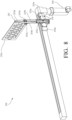
FIG. 8 is a perspective view of the exemplary rejection mechanism ofFIG. 7A ; -
FIG. 9A is a side view of the paddle of the exemplary rejection mechanism ofFIG. 8 at a first position along a track; -
FIG. 9B is a side view similar toFIG. 9A , but with the paddle of the exemplary rejection mechanism ofFIG. 8 at a second position along the track; -
FIG. 10 is an enlarged partial view of the track for the paddle of the exemplary rejection mechanism ofFIG. 8 ; -
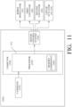
FIG. 11 is a schematic diagram of a control subsystem for a conveyor system that includes a rejection mechanism made in accordance with the present invention; and -
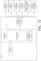
FIG. 12 is a schematic diagram of another control subsystem for a conveyor system that includes a rejection mechanism made in accordance with the present invention. - The present invention is a rejection mechanism for a conveyor system, which pushes parcels across a surface, such as an upper surface of a conveyor.
-
FIGS. 1 A and IB are perspective views of aconveyor system 10 for conveying and transferringparcels exemplary rejection mechanism 50 made in accordance with the present invention. As shown inFIGS. 1 A and IB, theconveyor system 10 further includes a first conveyor (or "pick conveyor") 20, a second conveyor (or "place conveyor') 30 downstream of thefirst conveyor 20, and a robot singulator (or robot) 35 for transferring parcels from thefirst conveyor 20 to thesecond conveyor 30. (For sake of clarity, only a portion of the robot is shown inFIG. 1A , and it is not shown at all inFIG. 1B ).Parcels robot singulator 35 end up in arejection zone 20a (indicated in dashed lines inFIG. 1A ) near aleading edge 20b of thefirst conveyor 20. Therejection zone 20a corresponds with a portion of an upper surface of thefirst conveyor 20, which is in the path of apaddle 52 of therejection mechanism 50, as further described below. Of course, parcels can also be accessed and engaged by therobot singulator 35 in therejection zone 20a; in other words, parcels are not exclusively engaged by therejection mechanism 50 in this area, as should become clear in the discussion that follows. - As evidenced by viewing
FIGS. 1A and1B in sequence, and as further described below, therejection mechanism 50 is selectively activated to pushparcels rejection zone 20a off of thefirst conveyor 20 and onto arejection chute 40 positioned to the side of thefirst conveyor 20 for subsequent sorting or recirculation back to thefirst conveyor 20. Following discharge of theparcels rejection chute 40, therejection mechanism 50 is returned to its home position, and thefirst conveyor 20 is indexed forward to facilitate subsequent sorting of any remaining parcels located on thefirst conveyor 20. As further described below with reference toFIG. 11 , operation of thefirst conveyor 20,second conveyor 30, and/or therobot singulator 35 are, in at least some embodiments, regulated by acontrol subsystem 300. -
FIG. 2 is a perspective view of theexemplary rejection mechanism 50, in isolation from the other components of theconveyor system 10 shown inFIGS. 1A and1B . -
FIG. 3 is a sectional view of the paddle of the exemplary rejection mechanism ofFIG. 2 taken along line 3-3 ofFIG. 2 . - Referring now to
FIGS. 1A ,1B , and2 , therejection mechanism 50 includes apaddle 52 that is mounted on alinear actuator 54, such that thepaddle 52 can be moved between a first (or home) position, as shown inFIG. 1A , and a second position, as shown inFIG. 1B , via thelinear actuator 54. In this exemplary embodiment, thelinear actuator 54 is a motor-controlled actuator, with acarriage 54a that moves between the first position and the second position. Many suitable linear actuators are commercially available. For example, one suitable linear actuator for this purpose is manufactured and distributed by Schneider Electric USA of Andover, Massachusetts, Model. No. PAS42BB. Of course, this is only one example of a suitable actuator, and many other forms of pneumatic or motor-controlled actuators could be incorporated into therejection mechanism 50 and still enable therejection mechanism 50 to operate as intended and described herein. For example, in alternative embodiments, thelinear actuator 54 may be a rod-less pneumatic actuator, such as that manufactured and distributed by Festo Corporation of Hauppauge, New York, Model No. DGC-32-1200-KF-YSRW-A ZUB-F-M. As further described below with reference toFIG. 11 , in some embodiments, operation of the linear actuator 54 (i.e., movement of thecarriage 54a) may be regulated, at least in part, by acontrol subsystem 300. - Referring now specifically to
FIG. 2 , in this exemplary embodiment, thepaddle 52 has a unitary construction. According to the invention the paddle includes: alower bracket portion 52a; anupright portion 52b that extends from thelower bracket portion 52a; and alateral wall portion 52c that extends from theupright portion 52b. Specifically, in this exemplary embodiment, thelateral wall portion 52c extends horizontally from theupright portion 52b and is in a perpendicular orientation relative to theupright portion 52b of thepaddle 52. Thelower bracket portion 52a is mounted to thecarriage 54a of thelinear actuator 54 by one ormore fasteners 56, such as bolts or similar conventional fasteners. - Referring now again to
FIGS. 1A and1B , therejection mechanism 50 is positioned relative to thefirst conveyor 20, such that, as thepaddle 52 moves from the first position to the second position, thepaddle 52 moves across therejection zone 20a toward therejection chute 40. The movement of thelateral wall portion 52c of thepaddle 52 across therejection zone 20a thus pushes anyparcels rejection zone 20a off of thefirst conveyor 20 and onto therejection chute 40. Thelinear actuator 54 of therejection mechanism 50 can thus be selectively activated to dischargeparcels first conveyor 20. - Although only a portion of the
linear actuator 54 is visible inFIGS. 1A and1B , as a result of the positioning of thesecond conveyor 30, thelinear actuator 54, in this embodiment, is mounted below theleading edge 20b of thefirst conveyor 20, such that theupright portion 52b of thepaddle 52 extends upward and adjacent to theleading edge 20b of thefirst conveyor 20, and thelateral wall portion 52c of thepaddle 52 is thus positioned over the upper surface of thefirst conveyor 20. In theconveyor system 10 shown inFIGS. 1A and1B , thesecond conveyor 30 is positioned downstream of and adjacent to thefirst conveyor 20, such that theupright portion 52b of thepaddle 52 extends upward through a gap between thefirst conveyor 20 and thesecond conveyor 30. Of course, in other embodiments, thelinear actuator 54 may alternatively be mounted to thesecond conveyor 30 and still enable theexemplary rejection mechanism 50 to function in the manner described herein. - Referring now to
FIGS. 1A ,1B , and2-3 , to preventparcels lateral wall portion 52c of thepaddle 52 as thepaddle 52 moves from the first position (FIG. 1A ) and across therejection zone 20a of thefirst conveyor 20 to the second position (FIG. 1B ), it is generally preferred that there is a minimal vertical gap between the bottom edge of thelateral wall portion 52c of thepaddle 52 and the upper surface of thefirst conveyor 20. For example, in some embodiments, this vertical gap may be approximately 10mm. Furthermore, in this exemplary embodiment, thepaddle 52 includes abrush 52d mounted to the front face of thelateral wall portion 52c, such that the bristles of thebrush 52d extend below the bottom edge of thelateral wall portion 52c to engage the upper surface of thefirst conveyor 20. In this regard, thebrush 52d thus substantially eliminates the gap existing between thelateral wall portion 52c and the upper surface of thefirst conveyor 20. As such, when thepaddle 52 is moved from the first position and across therejection zone 20a to the second position, thebrush 52d provides a sweeping force across the upper surface of thefirst conveyor 20, which ensures thatsmaller parcels paddle 52 and do not pass under thelateral wall portion 52c of thepaddle 52. Preferably, thebrush 52d is removably mounted to thelateral wall portion 52c by one ormore fasteners 57, such as bolts or similar conventional fasteners. - In at least some embodiments, the components of the
paddle 52 are constructed of steel or another suitable metal to prevent or limit the extent to which thepaddle 52 is deformed or broken down as a result of repeated trips across therejection zone 20a and engagement withparcels upright portion 52b of thepaddle 52 as a result of the forces acting on thelateral wall portion 52c, in this exemplary embodiment, a plurality ofopenings 52e are defined by, and thus can be characterized as being present within, thelateral wall portion 52c.Such openings 52e reduce the overall weight of thelateral wall portion 52c. - Referring still to
FIGS. 1A ,1B , and2-3 , and according to the invention, therejection mechanism 50 further includes away cover 60. The way cover 60 has afirst end 60a fixed in position relative to theconveyor system 10 and asecond end 60b mounted to thelateral wall portion 52c of thepaddle 52. Specifically, in this exemplary embodiment, thefirst end 60a of the way cover 60 is mounted to abracket 22 mounted to thefirst conveyor 20 by one or more fasteners (not shown), such as bolts or similar conventional fasteners, and thesecond end 60b of the way cover 60 is mounted to a rear face of thelateral wall portion 52c of thepaddle 52 by one ormore fasteners 55, such as bolts or similar conventional fasteners. - As evidenced again by viewing
FIGS. 1A and1B in sequence, the way cover 60 is configured to expand and contract with movement of thepaddle 52. As thepaddle 52 is moved by thelinear actuator 54 from the first position and across therejection zone 20a to the second position, the way cover 60 gradually expands from a contracted configuration (as shown inFIG. 1A ) to an expanded configuration (as shown inFIG. 1B ). In this exemplary embodiment, the way cover 60 is designed and configured such that, upon thepaddle 52 reaching the second position (FIG. 1B ), the way cover 60 is fully expanded, resulting in a substantially flat upper surface of theway cover 60. The way cover 60 thus provides a trailing wall behind thelateral wall portion 52c of thepaddle 52, which fill in the space behind thelateral wall portion 52c of thepaddle 52 as thepaddle 52 moves from the first position to the second positon, thereby preventing any parcels located on thefirst conveyor 20 from falling behind thelateral wall portion 52c of thepaddle 52 as thepaddle 52 moves between the first position and the second position. In this way, the way cover 60 prevents parcels from becoming trapped behind thelateral wall portion 52c of thepaddle 52 during operation of therejection mechanism 50. In the absence of theway cover 60, a parcel could flip over thelateral wall portion 52c of thepaddle 52 as thepaddle 52 moves from the first position and the second position, which could hinder or prevent thepaddle 52 from returning back to the first position. - Although not shown, as a further refinement, in some embodiments, the
conveyor system 10 may include a wall surface positioned above theway cover 60, which would push anyparcels paddle 52 is returned by thelinear actuator 54 to the first position. In other words, if any parcels flip over thelateral wall portion 52c of thepaddle 52 and onto the upper surface of theway cover 60, they would be pushed off the upper surface of the way cover 60 as thepaddle 52 returns back to the first position. -
FIG. 4 is an enlarged front view of the way cover 60 in isolation. - Referring now to
FIGS. 3 and4 , in this exemplary embodiment, the way cover 60 is comprised of afirst face plate 62, a second face plate 64, acover 66, and a plurality ofstiffeners 68. Thefirst face plate 62, which is at thesecond end 60b of theway cover 60, is mounted to thelateral wall portion 52c of thepaddle 52. To this end, thefirst face plate 62 defines a plurality ofopenings 63 corresponding to a plurality of openings defined by thelateral wall portion 52c, so that thefirst face plate 62 can be mounted to thelateral wall portion 52c via one ormore fasteners 55, such as bolts or similar conventional fasteners. In this exemplary embodiment, thefirst face plate 62 can be characterized as including three sections: afirst side section 62a; asecond side section 62b; and atop section 62c extending between the first andsecond side sections first face plate 62 substantially corresponds to that of thelateral wall portion 52c of thepaddle 52. - Referring still to
FIGS. 3 and4 , the second face plate 64 is mounted to a component of theconveyor system 10 to hold thefirst end 60a of the way cover 60 in a fixed position as thepaddle 52 moves thefirst face plate 62, and thus thesecond end 60b of theway cover 60, across therejection zone 20a. In this exemplary embodiment, and as mentioned above, the second face plate 64 is mounted to thebracket 22, which is shown inFIGS. 1A and1B . The shape of the second face plate 64 preferably corresponds to that of thefirst face plate 62, and thus, in this exemplary embodiment, thelateral wall portion 52c of thepaddle 52. Although not shown, the second face plate 64 thus also defines a plurality of openings corresponding to a plurality of openings defined by thebracket 22, so that the second face plate 64 can be mounted to thebracket 22 via one or more fasteners (not shown), such as bolts or similar conventional fasteners - Referring now to
FIGS. 1A ,1B , and2-4 , to facilitate extension and contraction of theway cover 60, the opposing ends 66a, 66b of thecover 66 are mounted to thefirst face plate 62 and the second face plate 64, and thecover 66 is comprised of a flexible fabric or similar material that can readily expand or contract as thepaddle 52 is moved between the first position and the second position.Multiple stiffeners 68 are positioned along the length of thecover 66 between the opposing ends 66a, 66b of thecover 66, and thesestiffeners 68 are mounted to and enclosed by thecover 66. Thestiffeners 68 maintain the shape of the trailing wall established by the way cover 60 as thepaddle 52 moves between the first position and the second position. In this exemplary embodiment, thestiffeners 68 are at equally spaced intervals along the length of theway cover 60. Furthermore, in this exemplary embodiment, eachstiffener 68 is constructed of a metal plate having a shape corresponding to that of thefirst face plate 62 and thelateral wall portion 52c of thepaddle 52. Accordingly, like thefirst face plate 62, eachstiffener 68 can be characterized as including three sections: a first side section; a second side section; and a top section extending between the first and second side sections. Thecover 66 extends along and fully covers the first side section, the second side section, and the top section of eachstiffener 68. Thus, thecover 66 establishes a three-sided wall (two side walls and a top wall), which expands and contracts with movement of thepaddle 52. As shown, the flexible material of thecover 66 is configured to fold in an accordion-like manner as thepaddle 52 is moved from the second position to the first position and the way cover 60 contracts. In this regard, the way cover 60 may also be referred to as a "bellows." - As perhaps best shown in
FIG. 3 , in this exemplary embodiment, eachstiffener 68 includes atip 69 on at least one of its sides. Specifically, in this exemplary embodiment, each side (only one of which is shown inFIG. 3 ) of eachstiffener 68 terminates at atip 69. Eachtip 69 is configured to engage and move along an upper surface of thefirst conveyor 20 as thepaddle 52 moves across therejection zone 20a. In this exemplary embodiment, the lowermost portion of eachtip 69 and the lowermost portion of thebrush 52d reside in substantially the same plane. Thetips 69 maintain thelateral wall portion 52c of thepaddle 52 in a generally parallel orientation relative to the upper surface of thefirst conveyor 20 and reduce the strain imposed on theupright portion 52b caused by the weight of thelateral wall portion 52c. To ensure that eachtip 69 effectively glides across the upper surface of thefirst conveyor 20 and will not damage the upper surface of thefirst conveyor 20, eachtip 69 is preferably constructed from a material with a low coefficient of friction and high durability, such as an ultra-high molecular weight polyethylene (UHMW). - Although not shown, as a further refinement, in some embodiments, the way cover 60 may further include a plurality of lamellas (or plates) provided along each wall of the
cover 66. In such embodiments, each lamella would be mounted to a respective wall of thecover 66, such that the lamellas effectively stack upon each other as the way cover 60 contracts. In such embodiments, the lamellas effectively cover the"valleys" resulting from thecover 66 being folded into an accordion-like construction, thereby preventingparcels - In some alternative embodiments, rather than a"bellows" structure, the way cover may be constructed as to transition between a rolled-up configuration and an extended (or unrolled) configuration. Like the way cover 60 described above with reference to
FIGS. 3-4 , the way cover would have a first end fixed in position relative to the conveyor system and a second end mounted to the lateral wall portion of the paddle. However, it would not include any of theplates 62, 64 orstiffeners 68 described above with reference toFIGS. 3-4 . Rather, the way cover would include a single length of material that is rolled onto a rod, much like a roll-up window shade. When thepaddle 52 is in the first position, the material would be stored on the rod in the rolled- up configuration. As thepaddle 52 moves to the second position, the rod would rotate, and the material would unfurl from the rod until the way cover is in the extended (or unrolled) configuration. In that extended (or unrolled) configuration, the way cover would again provide a wall extending across therejection zone 20a of thefirst conveyor 20. -
FIGS. 5 A and 5B are perspective views of anotherconveyor system 100 for conveying and transferringparcels exemplary rejection mechanism 150 falling outside the literal scope ofClaim 1. As shown inFIGS. 5 A and 5B , theconveyor system 100 includes each of the components (i.e., thefirst conveyor 20, thesecond conveyor 30,robot singulator 35, and rejection chute 40) of theconveyor system 10 illustrated and described above with reference toFIGS. 1 A and IB , where each respective component includes the same features and provides the same functionality as described above. - As evidenced by viewing
FIGS. 5A and5B in sequence, like therejection mechanism 50 described above with reference toFIGS. 1A , IB, and 2, therejection mechanism 150 is selectively activated to pushparcels rejection zone 20a off of thefirst conveyor 20 and onto arejection chute 40 positioned to the side of thefirst conveyor 20 for subsequent sorting or recirculation back to thefirst conveyor 20. Following discharge of theparcels rejection chute 40, therejection mechanism 150 can be returned to its home position, and thefirst conveyor 20 is indexed forward to facilitate subsequent sorting of any remaining parcels located on thefirst conveyor 20. As further described below with reference toFIG. 12 , movement of thefirst conveyor 20,second conveyor 30, and/or therobot singulator 35 are, in at least some embodiments, regulated by acontrol subsystem 400. -
FIG. 6 is a perspective view of theexemplary rejection mechanism 150, in isolation from the other components of theconveyor system 100 shown inFIGS. 5A and5B . - Referring now to
FIGS. 5A ,5B , and6 , therejection mechanism 150 includes apaddle 152 that is mounted on alinear actuator 154, such that thepaddle 152 can be moved between a first (or home) position, as shown inFIG. 5 A , and a second position, as shown inFIG. 5B , via thelinear actuator 154. In this exemplary embodiment, thelinear actuator 154 is a motor-controlled actuator, with acarriage 154a that moves between the first position and the second position. Many suitable linear actuators are commercially available. For example, one suitable linear actuator for this purpose is manufactured and distributed by Schneider Electric USA of Andover, Massachusetts, Model. No. PAS42BB. Of course, this is only one example of a suitable actuator, and many other forms of pneumatic or motor-controlled actuators could be incorporated into therejection mechanism 150 and still enable therejection mechanism 150 to operate as intended and described herein. For example, in alternative embodiments, thelinear actuator 154 may be a rod-less pneumatic actuator, such as that manufactured and distributed by Festo Corporation of Hauppauge, New York, Model No. DGC- 32-1200-KF-YSRW-A ZUB-F-M. As further described below with reference toFIG. 12 , in some embodiments, operation of the linear actuator 154 (i.e., movement of thecarriage 154a) may be regulated, at least in part, by acontrol subsystem 400. - As perhaps best shown in
FIG. 6 , thepaddle 152 includes: alower bracket portion 152a; anupright portion 152b that extends from thelower bracket portion 152a; and alateral wall portion 152c that extends from theupright portion 152b. The respective components of thepaddle 152 may be constructed from the same materials as those of thepaddle 52 of therejection mechanism 50 described above with reference toFIGS.1A , IB, and 2. Furthermore, thelateral wall portion 152c of thepaddle 152 may also define a plurality of openings for weight reduction, like therejection mechanism 50 described above with reference toFIGS. 1A , IB, and 2. Thelower bracket portion 152a is mounted to thecarriage 154a of the linear actuator by one ormore fasteners 156, such as bolts or similar conventional fasteners. - Referring still to
FIG. 6 , theupright portion 152b of thepaddle 152 includes anupper section 153a and alower section 153b connected together by ahinge 153c. Thelateral wall portion 152c is operably connected to and extends from theupper section 153a of theupright portion 152b, while thelower section 153b of theupright portion 152b is operably connected to thelower bracket portion 152a of thepaddle 152. In this exemplary embodiment, thelower section 153b of theupright portion 152b and thelower bracket portion 152a are formed from a single piece of material, i.e., have a unitary construction. As a result of the foregoing construction, theupper section 153a of theupright portion 152b can thus effectively rotate about an axis of rotation defined by thehinge 153c to transition thelateral wall portion 152c of thepaddle 152 between: (i) an engaged position, in which thelateral wall portion 152c of the paddle is in a substantially horizontal orientation (i.e., extends perpendicular relative to thelower section 153b of theupright portion 152b); and (ii) a disengaged position, in which thelateral wall portion 152c of the paddle is in a substantially vertical orientation (i.e., extends vertically relative to thelower section 153b of theupright portion 152b). As a further refinement, thepaddle 152 also includes astop 153d mounted to thelower section 153b of theupright portion 152b, which prevents rotation of theupper section 153a of theupright portion 152b beyond a predefined limit when thelateral wall portion 152c of thepaddle 152 is transitioned to a disengaged position. - Referring now again to
FIGS. 5A and5B , therejection mechanism 150 is positioned relative to thefirst conveyor 20, such that, as thepaddle 152 moves from the first position to the second position while thelateral wall portion 152c is in the engaged position, thepaddle 152 moves across therejection zone 20a toward therejection chute 40. The movement of thelateral wall portion 152c of thepaddle 152 across therejection zone 20a, while in the engaged position, thus pushes anyparcels rejection zone 20a off of thefirst conveyor 20 and onto therejection chute 40. Thelinear actuator 154 of therejection mechanism 150 can thus be selectively activated while thelateral wall portion 152c is in the engaged position to dischargeparcels first conveyor 20. - Referring still to
FIGS. 5 A and 5B , the linear actuator 154 (only a portion of which is shown inFIGS. 5A and5B ) is mounted below theleading edge 20b of thefirst conveyor 20, such that both theupper section 153a and thelower section 153b of theupright portion 152b of thepaddle 152 extend upward and adjacent to theleading edge 20b of thefirst conveyor 20 when thelateral wall portion 152c is in the engaged position. In theconveyor system 100 shown inFIGS. 5A and5B , thesecond conveyor 30 is positioned downstream of and adjacent to thefirst conveyor 20, such that theupright portion 152b of thepaddle 152 extends upward through a gap between thefirst conveyor 20 and thesecond conveyor 30. Of course, thelinear actuator 154 may alternatively be mounted to thesecond conveyor 30 and still enable theexemplary rejection mechanism 150 to function in the manner described herein. - Referring still to
FIGS. 5A and5B , to preventparcels lateral wall portion 152c of thepaddle 152 as thepaddle 152 transitions from the first position across therejection zone 20a of thefirst conveyor 20 to the second position while thelateral wall portion 152c is in the engaged position, it is generally preferred that there is a minimal vertical gap between the bottom edge of thelateral wall portion 152c of thepaddle 152 and the upper surface of thefirst conveyor 20. For example, in some embodiments, this vertical gap may be approximately 10mm. - Referring now to
FIG. 5B ,, after thelinear actuator 154 has moved thepaddle 152 from the first position to the second position, and thus pushed theparcels rejection zone 20a from thefirst conveyor 20 onto therejection chute 40, thelateral wall portion 152c of thepaddle 152 can be rotated from the engaged position to the disengaged position about thehinge 153c. Accordingly, when thelinear actuator 154 returns thepaddle 152 from the second position to the first position, thelateral wall portion 152c of thepaddle 152 does not pass back over therejection zone 20a. Rather, thelateral wall portion 152c is in a substantially vertical orientation during its return to the first position. Accordingly, in the event that any parcels have entered therejection zone 20a after thepaddle 152 has reached the second position, such parcels will not impede the movement of thepaddle 152 from the second position back to the first position, as thelateral wall portion 152c is no longer positioned over an upper surface of thefirst conveyor 20. After thepaddle 152 has returned to the first position, thelateral wall portion 152c of the paddle can be rotated from the disengaged position back to the engaged position (as shown inFIG. 5A ). - Referring again to
FIGS. 5A and5B , to facilitate rotation of thelateral wall portion 152c of thepaddle 152 between the engaged position and the disengaged position, theconveyor system 100 further includes a first pushingmechanism 160 and a second pushingmechanism 162. In this exemplary embodiment, and as best shown inFIG. 5 A , the first pushingmechanism 160 is a motor-controlled linear actuator, which includes anarm 160a that can be extended to engage thelateral wall portion 152c of thepaddle 152, rotating it about thehinge 153c from the disengaged position to the engaged position. Similarly, and as best shown inFIG. 5B , the second pushingmechanism 162 is a motor-controlled linear actuator, which includes anarm 162a that can be extended to engage thelateral wall portion 152c of thepaddle 152, rotating it about thehinge 153c from the engaged position to the disengaged position. Of course, many different types of linear actuators or other similar mechanisms may provide the desired rotation (or flipping) of thelateral wall portion 152c of thepaddle 152 between the engaged position and the disengaged position. - Referring now specifically to
FIG. 5 A , the first pushingmechanism 160 is mounted such that thearm 160a of the first pushingmechanism 160 can be extended in a substantially horizontal direction to engage thelateral wall portion 152c of thepaddle 152 when thepaddle 152 is in the first position. As thearm 160a of the first pushingmechanism 160 is extended, thelateral wall portion 152c rotates about the axis of rotation defined by thehinge 153c from the disengaged position to the engaged position. In other words, the first pushingmechanism 160 flips thelateral wall portion 152c from the disengaged position to the engaged position. Specifically, in this exemplary embodiment, the first pushingmechanism 160 is mounted to thesecond conveyor 30 by abracket 32. Of course, the first pushingmechanism 160 may be mounted in any suitable orientation which permits thearm 160a to extend and engage thelateral wall portion 152c of thepaddle 152 in the manner described above. - Referring now specifically to
FIG. 5B , the second pushingmechanism 162 is mounted such that thearm 162a of the second pushingmechanism 162 can be extended in a substantially vertical direction to engage thelateral wall portion 152c of thepaddle 152 when thepaddle 152 is in the second position. As thearm 162a of the second pushingmechanism 162 is extended, thelateral wall portion 152c rotates about the axis of rotation defined by thehinge 153c from the engaged position to the disengaged position. In other words, the second pushingmechanism 162 flips thelateral wall portion 152c from the engaged position to the disengaged position. Specifically, in this exemplary embodiment, the second pushingmechanism 162 is mounted to thefirst conveyor 20 below therejection chute 40. Thus, therejection chute 40 defines anopening 40a through which thearm 162a of the second pushingmechanism 162 can extend to engage thelateral wall portion 152c of thepaddle 152. Of course, the second pushingmechanism 162 may be mounted in any suitable orientation which permits thearm 162a of the second pushingmechanism 162 to extend and engage thelateral wall portion 152c of thepaddle 152 in the manner described above. - As further described below with reference to
FIG. 12 , operation of thelinear actuator 154, the first pushingmechanism 160, and/or the second pushingmechanism 162 are, in at least some embodiments, regulated by acontrol subsystem 400. -
FIGS. 7 A and 7B are perspective views of anotherconveyor system 200 for conveying and transferringparcels exemplary rejection mechanism 250 outside the literal scope ofClaim 1. As shown inFIGS. 7A and7B , theconveyor system 200 includes each of the components (i.e., thefirst conveyor 20, thesecond conveyor 30,robot singulator 35, and rejection chute 40) of theconveyor system 10 illustrated and described above with reference toFIGS. 1 A and IB , where each respective component includes the same features and provides the same functionality as described above. - As evidenced by viewing
FIGS. 7A and7B in sequence, like therejection mechanisms exemplary rejection mechanism 250 is selectively activated to pushparcels rejection zone 20a off of thefirst conveyor 20 and onto arejection chute 40 positioned to the side of thefirst conveyor 20 for subsequent sorting or recirculation back to thefirst conveyor 20. Following discharge of theparcels rejection chute 40, therejection mechanism 250 can be returned to its home position, and thefirst conveyor 20 is indexed forward to facilitate subsequent sorting of any remaining parcels located on thefirst conveyor 20. As further described below with reference toFIG. 11 , operation of thefirst conveyor 20,second conveyor 30, and/or therobot singulator 35 are, in at least some embodiments, regulated by acontrol subsystem 300. -
FIG. 8 is a perspective view of theexemplary rejection mechanism 250, in isolation from the other components of theconveyor system 200 shown inFIGS. 7 A and 7B . - Referring now to
FIGS. 7 A ,7B , and8 , therejection mechanism 250 includes apaddle 252 that is mounted on alinear actuator 254, such that thepaddle 252 can be moved between a first (or home) position, as shown inFIG. 7A , and a second position, as shown inFIG. 7B , via thelinear actuator 254. Thelinear actuator 254 is a motor-controlled actuator, with acarriage 254a that moves between the first position and the second position. Many suitable linear actuators are commercially available. For example, one suitable linear actuator for this purpose is manufactured and distributed by Schneider Electric USA of Andover, Massachusetts, Model. No. PAS42BB. Of course, this is only one example of a suitable actuator, and many other forms of pneumatic or motor-controlled actuators could be incorporated into therejection mechanism 250 and still enable therejection mechanism 250 to operate as intended and described herein. For example, in alternative embodiments, thelinear actuator 254 may be a rod-less pneumatic actuator, such as that manufactured and distributed by Festo Corporation of Hauppauge, New York, Model No. DGC-32-1200-KF-YSRW-A ZUB-F-M. As further described below with reference toFIG. 11 , in at least some embodiments, operation of the linear actuator 254 (i.e., movement of thecarriage 254a) is regulated by acontrol subsystem 300. - As perhaps best shown in
FIG. 8 , in this exemplary embodiment, thepaddle 252 includes: alower bracket portion 252a; anupright portion 252b that extends from thelower bracket portion 252a; and alateral wall portion 252c that extends from theupright portion 252b. The respective components of thepaddle 252 may be constructed from the same materials as those of thepaddles rejection mechanisms lateral wall portion 252c of thepaddle 252 may also define a plurality of openings for weight reduction, like therejection mechanisms lower bracket portion 252a is mounted to thecarriage 254a of the linear actuator by one ormore fasteners 256, such as bolts or similar conventional fasteners. - Referring still to
FIG. 8 , in this exemplary embodiment, thelower bracket portion 252a and theupright portion 252b are formed from a single piece of material, i.e., have a unitary construction. Thelateral wall portion 252c is connected to theupright portion 252b by ahinge 253a. As a result of the foregoing construction, thelateral wall portion 252c is able to rotate about an axis of rotation defined by thehinge 253a between: (i) an engaged position, in which thelateral wall portion 252c of thepaddle 252 is in a substantially horizontal orientation (i.e., extends perpendicular relative to theupright portion 252b of the of the paddle 252); and (ii) a disengaged position, in which thelateral wall portion 252c is in a substantially vertical orientation (i.e., extends vertically relative to theupright portion 252b of the paddle). To facilitate movement of thelateral wall portion 252c between the engaged position and the disengaged position, in this exemplary embodiment, theupright portion 252b defines aslit 252d in which thelateral wall portion 252c can travel through and rest within, as further described below. - Referring still to
FIG. 8 , in this exemplary embodiment, to rotate thelateral wall portion 252c of thepaddle 252 about the axis of rotation defined by thehinge 253a from the engaged position to the disengaged position, afirst linkage 253b (or "linear slide") is mounted for sliding movement in a channel defined by aguide 253c, which, is mounted to a surface of theupright portion 252b of thepaddle 252. In this exemplary embodiment, a distal end of thefirst linkage 253b is operably connected to thelateral wall portion 252c of thepaddle 252, such that thefirst linkage 253b can be manipulated to slide thefirst linkage 253b within theguide 253c and move thelateral wall portion 252c between the engaged and disengaged position. Specifically, in this embodiment, a distal end of thefirst linkage 253b is pivotally connected to a proximal end of asecond linkage 253d (or "connector linkage"), preferably via a pin connection. A distal end of thesecond linkage 253d is then pivotally connected to thelateral wall portion 252c of thepaddle 252. Acam follower 253e is mounted for rotation with respect to, and extends from, thefirst linkage 253b to control movement of thefirst linkage 253b within theguide 253c, as further described below. - Referring now to
FIGS. 7A and7B , the linear actuator 254 (only a portion of which is shown inFIGS. 7A and7B ) is mounted below theleading edge 20b of thefirst conveyor 20, such that theupright portion 252b of thepaddle 252 extends upward and adjacent to theleading edge 20b of thefirst conveyor 20. In theconveyor system 200 shown inFIGS. 7A and7B , thesecond conveyor 30 is positioned downstream and adjacent to thefirst conveyor 20, such that theupright portion 252b of thepaddle 252 extends upward through a gap between thefirst conveyor 20 and thesecond conveyor 30. Of course, in other embodiments, thelinear actuator 254 may alternatively be mounted to thesecond conveyor 30 and still enable theexemplary rejection mechanism 250 to function in the manner described herein. -
FIGS. 9A and9B are various side views of thepaddle 252 at different positions along a track. - Referring now to
FIGS. 7A ,7B ,9A , and9B , thecam follower 253e is positioned within a track 260 (or "linear cam"), such that, as thelinear actuator 254 moves thepaddle 252 between the first position (FIG. 7A ) and the second position (FIG. 7B ), thecam follower 253e is moved along thetrack 260 to transition thelateral wall portion 252c of the paddle between the engaged and disengaged position, as further described below. Although not shown inFIGS. 7A and7B , in this embodiment, thetrack 260 is mounted below the leading edge of thefirst conveyor 20. Of course, in other embodiments, thetrack 260 may alternatively be mounted to thesecond conveyor 30 and still enable theexemplary rejection mechanism 250 to function in the manner described herein. As shown inFIGS. 9A and9B , thetrack 260 is defined by, and can be characterized as including: anupper track portion 260a; alower track portion 260b; a firstinclined ramp 260c, which interconnects theupper track portion 260a and thelower track portion 260b; and a secondinclined ramp 260d, which also interconnects theupper track portion 260a and thelower track portion 260b. In this regard, thetrack 260 is a closed loop. - Referring now to
FIGS. 7A ,7B ,8 ,9A , and9B , as thepaddle 252 is moved from the first position (FIG. 7A ) to the second position (FIG. 7B ), thecam follower 253e is correspondingly moved from a first portion of the track 260 (FIG. 9A ), which, in this embodiment, is an upper-right portion of thetrack 260, to a second portion of thetrack 260, which, in this embodiment, is lower-left portion of thetrack 260. During movement from the first position to the second position, thelateral wall portion 252c of thepaddle 252 is in the engaged position, and the weight of thelateral wall portion 252c of thepaddle 252 causes it to remain in the engaged position. Thus, as thelateral wall portion 252c of the paddle moves over therejection zone 20a of thefirst conveyor 20, as thepaddle 252 is moved from the first position to the second position by thelinear actuator 254, anyparcels rejection zone 20a are pushed off of thefirst conveyor 20 and onto therejection chute 40 - Referring still to
FIGS. 7A ,7B ,8 ,9A , and9B , during the movement of thepaddle 252 from the first position to the second position, thecam follower 253e moves along theupper track portion 260a until reaching the firstinclined ramp 260c, which, in this case, slopes downwardly to thelower track portion 260b. Upon reaching the firstinclined ramp 260c, thecam follower 253e then moves from theupper track portion 260a to thelower track portion 260b. As thecam follower 253e transitions down the firstinclined ramp 260c to thelower track portion 260b, thefirst linkage 253b slides to a lower position within theguide 253c. In turn, as thefirst linkage 253b slides downward in the channel defined by theguide 253c, a torque is effectively applied to thelateral wall portion 252c of thepaddle 252 via thesecond linkage 253d, which causes thelateral wall portion 252c to rotate about the axis of rotation defined by thehinge 253a from the engaged position to the disengaged position. Once rotated into the disengaged position, the center of gravity of thepaddle 252 has moved to the opposite side of thehinge 253a, such that the weight of thepaddle 252 now biases it to remain in the disengaged position. Thelateral wall portion 252c is now in a substantially vertical orientation during its return to the first position. As such, in the event any parcels have entered therejection zone 20a after thepaddle 252 has reached the second position, such parcels will not impede movement of thepaddle 252 from the second position back to the first position, as thelateral wall portion 252c is no longer positioned over an upper surface of thefirst conveyor 20. - Referring still to
FIGS. 7A ,7B ,8 ,9A , and9B , as thelinear actuator 254 moves thepaddle 252 from the second position back to the first position, thecam follower 253e moves from the second (lower-left) portion of thetrack 260 across thelower track portion 260b until reaching the secondinclined ramp 260d, which, in this case, slopes upwardly. Upon reaching the secondinclined ramp 260d, thecam follower 253e then moves from thelower track portion 260b to theupper track portion 260a. As thecam follower 253e moves up the secondinclined ramp 260d to theupper track portion 260a, thefirst linkage 253b slides to a higher position within theguide 253c. In turn, as thefirst linkage 253b slides upwardly in the channel defined by theguide 253c, a torque is effectively applied to thelateral wall portion 252c of thepaddle 252 via thesecond linkage 253d, which causes thelateral wall portion 252c to rotate about the axis of rotation defined by thehinge 253a from the disengaged position to the engaged position, and thepaddle 252 is again ready to push parcels located in therejection zone 20a onto therejection chute 40. - In addition to changing the elevation and moving the
cam follower 253e between theupper track portion 260a and thelower track portion 260b, the firstinclined ramp 260c and the secondinclined ramp 260d are also configured to prevent thecam follower 253e from receiving too much thrust, as excessive thrust can result in a whipping action and damaging impact to thecam follower 253e and/or thepaddle 252 resulting from a sudden change in direction. In this regard, thrust is dependent on the incline angle at any given instant, from no thrust at 0° to maximum thrust at 45° to no thrust at 90°. This potential for damaging impact is further exacerbated by the fact that thecam follower 253e is accelerating into the first and secondinclined ramps paddle 252 between the first position and the second position, or vice versa. Thus, the first and secondinclined ramps paddle 252 about the axis of rotation defined by thehinge 253a, but prevent damaging impact of thecam follower 253e as it engages each of the first and secondinclined ramps -
FIG. 10 shows an enlarged partial view of the secondinclined ramp 260d of thetrack 260. As shown inFIG. 10 , in this exemplary embodiment, the secondinclined ramp 260d is formed from three parabolic track sections S1, S2, S3 spliced together at points of continuity C1, C2. In this embodiment, the shape of the respective track sections S1, S2, S3 are define by the following equations:
inclined ramp 260c is formed in a similar manner, i.e., formed from three parabolic track sections spliced together, except the slope defined by the firstinclined ramp 260c is inverted relative to the slope defined by the secondinclined ramp 260d. -
FIG. 11 is a schematic diagram of acontrol subsystem 300, which can be utilized with theconveyor systems FIGS. 1A ,1B ,7A , and7B . As shown inFIG. 11 , thecontrol subsystem 300 includes one ormore cameras 310, where eachcamera 310 is configured to collect environmental image data regarding the positioning ofparcels conveyor system control subsystem 300 may include a first camera and a second camera. In such embodiments, the first camera is preferably positioned adjacent to therobot singulator 35 and is focused on the location where a selectedparcel robot singulator 35, which, in this case is thefirst conveyor 20. The first camera thus collects two-dimensional and/or three-dimensional image data, which assists therobot singulator 35 in identifying the location of aparcel second conveyor 30. The second camera is preferably positioned adjacent to thesecond conveyor 30 and focused on the area(s) whereparcels 12a engaged by therobot singulator 35 are to be delivered. The second camera thus collects two-dimensional and/or three-dimensional image data that indicates whether a parcel has been successfully delivered to thesecond conveyor 30 by therobot singulator 35. Suitable cameras for use in the present invention include three-dimensional image sensors manufactured and distributed by ifM Efector Inc. of Malvern, Pa. - Referring still to
FIG. 11 , thecontrol subsystem 300 further includes acomputer 320 operably connected to the camera(s) 310, such that thecomputer 320 can receive and process image data from the camera(s) 310. In this regard, thecomputer 320 includes aprocessor 330 for executing instructions (routines) stored in amemory component 340 or other computer-readable medium. - Referring still to
FIG. 11 , thecontrol subsystem 300 further includes amotor control system 350, which receives instructions from thecomputer 320 and controls operation of certain components of theconveyor system motor control system 350. For example, suitable motor control systems for use in the present invention include: ControlLogix® controllers, which are part of the Allen-Bradley product line manufactured and distributed by Rockwell Automation, Inc. of Milwaukee, Wis.; and PacDrive™ controllers manufactured and distributed by Schneider Electric USA of Andover, Massachusetts. In this exemplary embodiment, thefirst conveyor 20, thesecond conveyor 30, therobot singulator 35, and thelinear actuator rejection mechanism motor control system 350. - Referring now to
FIGS. 1A ,1B ,7A ,7B , and11 , in some implementations, theconveyor system parcels first conveyor 20 by having one ormore cameras 310 acquire image data identifying the position of aparcel 12a located near theleading edge 20b of thefirst conveyor 20 intended for transport to thesecond conveyor 30. Such image data is then transmitted to and processed by thecomputer 320, which, in turn, communicates instructions to themotor control system 350. Based on the instructions received from thecomputer 320, themotor control system 350 then communicates instructions (or signals) to the robot singulator 35 (or the motors and/or linear actuators responsible for movement thereof), which cause therobot singulator 35 to move toward, engage, and transport thetarget parcel 12a to thesecond conveyor 30, as shown, e.g., by viewingFIGS. 1A and1B in sequence. One ormore cameras 310 may then capture image data which is processed by thecomputer 320 to verify delivery of thetarget parcel 12a to thesecond conveyor 30. Upon such verification, thecomputer 320 can then communicate instructions to themotor control system 350, which subsequently causes thesecond conveyor 30 to index forward and clear a path for subsequent parcels intended for delivery to thesecond conveyor 30. - Following transport of the
target parcel 12a off of thefirst conveyor 20, thecomputer 320 can communicate instructions to themotor control system 350, which causes thelinear actuator rejection mechanism paddle parcels rejection zone 20a onto therejection chute 40, and then return thepaddle computer 320 to themotor control system 350 causing actuation of thelinear actuator rejection mechanism computer 320 receiving image data from one ormore cameras 310 indicating that one ormore parcels rejection zone 20a exhibits a predefined characteristics (e.g., certain dimensions or shape) that signifies theparcel robot singulator 35 may transport multiple parcels to thesecond conveyor 30 before thelinear actuator rejection mechanism paddle computer 320 communicates instructions to themotor control system 350 which causes thefirst conveyor 20 to index forward to move parcels remaining on thefirst conveyor 20 towards the leadingedge 20b of thefirst conveyor 20. The foregoing process can then be repeated to process the remainder ofparcels first conveyor 20. -
FIG. 12 is a schematic diagram of anothercontrol subsystem 400, which can be utilized with theconveyor system 100 described above with respect toFIGS. 5A and5B . As shown inFIG. 12 , thecontrol subsystem 400 includes each component and functions in the same manner as thecontrol subsystem 300 described above with reference toFIG. 11 , except that themotor control system 350 is further operably connected to the first pushingmechanism 160 and the second pushingmechanism 162. Accordingly, thecontrol subsystem 400 can be utilized to processparcels control subsystem 300 described above with reference toFIG. 11 . However, in addition to the steps identified in the exemplary implementation above, thecomputer 320 will also communicate instructions to themotor control system 350 which: (i) causes actuation of the second pushingmechanism 162, after thepaddle 152 has reached the second position, to engage thelateral wall portion 152c of thepaddle 152 and rotate it from the engaged position to the disengaged position; and (ii) causes actuation of the first pushingmechanism 160, after thepaddle 152 has returned to the first position from the second position, to engage thelateral wall portion 152c of thepaddle 152 and rotate it from the disengaged position to the engaged position. - Although the
exemplary rejection mechanisms first conveyor 20 andsecond conveyor 30 in theconveyor systems parcels first conveyor 20 to thesecond conveyor 30, it should be appreciated that the use of theexemplary rejection mechanisms exemplary rejection mechanisms exemplary rejection mechanisms - Furthermore, although the present invention is characterized as a"rejection mechanism," it is not necessarily only for"rejecting" nonconveyables that exceed size and/or weight limitations. Rather, the
rejection mechanisms rejection mechanism pick conveyor 20, so that those parcels can be more easily engaged by therobot singulator 35. For another example, eachrejection mechanism more cameras 310 of thecontrol subsystem rejection mechanisms
Claims (5)
- A rejection mechanism (50) for a conveyor system (10) including a conveyor for conveying parcels, comprising:a linear actuator (54);a paddle (52) mounted to the linear actuator (54) for movement between a first position and a second position, wherein the paddle (52) includes (i) a lower bracket portion (52a) for mounting the paddle (52) to the linear actuator (54), (ii) an upright portion (52b) extending upward and adjacent to an edge of the conveyor, and (iii) a lateral wall portion (52c) that extends from the upright portion (52b);and wherein, in use, the lateral wall portion (52c) is positioned over a portion of an upper surface of the conveyor as the paddle (52) is moved from the first position to the second position, such that parcels positioned on the conveyor in a path of the lateral wall portion (52c) are pushed by the lateral wall portion (52c) as the paddle (52) is moved from the first position to the second position;characterized in thatthe rejection mechanism (50) further comprises a way cover (60) having a first end (60a) fixed in position and a second end (60b) mounted to the lateral wall portion (52c) of the paddle (52); andwherein the way cover (60) expands and contracts with movement of the paddle (52).
- The rejection mechanism according to claim 1, wherein the way cover (60) includes multiple stiffeners (68) and a flexible cover (66) positioned over the multiple stiffeners.
- A conveyor system (10), comprising:a first conveyor (20) for conveying a flow of multiple parcels (12a-c);a rejection chute (40); anda rejection mechanism (50) in accordance with Claim 1 or Claim 2.
- The conveyor system (10) according to claim 3, and further comprising:
a robot singulator (35) configured to engage and transfer individual parcels in the flow of multiple parcels (12a-c) from the first conveyor (20) to a second conveyor (30). - The conveyor system according to claim 4, wherein the upright portion (52b) of the paddle (52) extends upward through a gap between the first conveyor (10) and the second conveyor (20).
Applications Claiming Priority (3)
| Application Number | Priority Date | Filing Date | Title |
|---|---|---|---|
| US201962854434P | 2019-05-30 | 2019-05-30 | |
| US201962863348P | 2019-06-19 | 2019-06-19 | |
| PCT/US2020/035201 WO2020243480A1 (en) | 2019-05-30 | 2020-05-29 | Rejection mechanism for a conveyor system |
Publications (4)
| Publication Number | Publication Date |
|---|---|
| EP3980358A1 EP3980358A1 (en) | 2022-04-13 |
| EP3980358A4 EP3980358A4 (en) | 2023-07-19 |
| EP3980358B1 true EP3980358B1 (en) | 2024-10-02 |
| EP3980358C0 EP3980358C0 (en) | 2024-10-02 |
Family
ID=73549587
Family Applications (1)
| Application Number | Title | Priority Date | Filing Date |
|---|---|---|---|
| EP20815630.7A Active EP3980358B1 (en) | 2019-05-30 | 2020-05-29 | Rejection mechanism for a conveyor system |
Country Status (6)
| Country | Link |
|---|---|
| US (1) | US11014767B2 (en) |
| EP (1) | EP3980358B1 (en) |
| CA (1) | CA3137543C (en) |
| ES (1) | ES3000448T3 (en) |
| MX (1) | MX394139B (en) |
| WO (1) | WO2020243480A1 (en) |
Families Citing this family (6)
| Publication number | Priority date | Publication date | Assignee | Title |
|---|---|---|---|---|
| US10625956B2 (en) * | 2017-02-10 | 2020-04-21 | Symbotic, LLC | Palletizer-depalletizer system for distribution facilities |
| US11155424B2 (en) * | 2019-11-07 | 2021-10-26 | Cnh Industrial America Llc | Pneumatically inflated pillow for grain bin unload |
| US11753256B2 (en) | 2020-06-22 | 2023-09-12 | Material Handling Systems, Inc. | Conveyor system with multiple robot singulators |
| US11851293B2 (en) | 2021-05-20 | 2023-12-26 | Material Handling Systems, Inc. | Trapdoor rejection subsystem for a conveyor system |
| FR3131233B1 (en) | 2021-12-28 | 2023-12-08 | Solystic | Package sorting method for feeding an injection conveyor from a retractable feed conveyor and package sorting installation for implementing such a process |
| US20230271791A1 (en) * | 2022-02-28 | 2023-08-31 | Material Handling Systems, Inc. | System and method for transferring parcels |
Family Cites Families (18)
| Publication number | Priority date | Publication date | Assignee | Title |
|---|---|---|---|---|
| US4103789A (en) * | 1977-03-28 | 1978-08-01 | Adolph Coors Company | Unitized loading system |
| IT1122898B (en) | 1979-08-30 | 1986-04-30 | Francesco Canziani | SELECTION AND SORTING EQUIPMENT FOR OBJECTS |
| US5894918A (en) * | 1997-01-06 | 1999-04-20 | United Parcel Service Of America, Inc. | Conveyor having serpentine capabilities |
| US5868239A (en) * | 1997-01-27 | 1999-02-09 | United Parcel Service Of America, Inc. | Conveyor including controlled package ejection capabilities |
| US5950798A (en) * | 1997-02-26 | 1999-09-14 | United Parcel Services Of America | Air distribution systems for shoe sorter |
| US6409451B1 (en) * | 2000-04-13 | 2002-06-25 | Ibp, Inc. | Item handler and method for flow through storage |
| US6446782B1 (en) * | 2000-06-16 | 2002-09-10 | Rapistan Systems Advertising Corp. | Shuttle top diverter |
| US7261198B2 (en) * | 2002-02-19 | 2007-08-28 | Lockheed Martin Corporation | Bi-directional package divert mechanism and method of use |
| US6516937B1 (en) * | 2002-05-17 | 2003-02-11 | Lockheed Martin Corporation | Under roller conveyor pusher assembly |
| NL1028578C1 (en) * | 2005-03-21 | 2006-09-25 | Cologic B V | Device and method for transferring products. |
| FR2910879B1 (en) * | 2006-12-29 | 2009-04-03 | Michel Lamamy | DEVICE FOR OVERPACKING AT LEAST ONE OBJECT |
| DE102009049174A1 (en) * | 2009-10-13 | 2011-04-21 | Kuka Roboter Gmbh | Transport system for piece goods and method for unloading piece goods |
| FR2954285B1 (en) * | 2009-12-22 | 2012-02-03 | Automatisation Et Renovation Du Conditionnement Dans Les Ind Laitieres Arcil | METHOD AND MACHINE FOR OVERPACKING ARTICLES FOR FORMING LOTS OF ARTICLES, OF THE TYPE COMPRISING A SINGLE PLURALITY OF ARTICLES AND A CARDBOARD OVERPACK. |
| US9950878B2 (en) * | 2016-09-09 | 2018-04-24 | Top Tier, Llc | Case manipulator for a palletizer system |
| WO2018089486A1 (en) * | 2016-11-08 | 2018-05-17 | Berkshire Grey Inc. | Systems and methods for processing objects |
| EP3544911B1 (en) | 2016-11-28 | 2023-10-18 | Berkshire Grey Operating Company, Inc. | System for providing singulation of objects for processing |
| MX2019014605A (en) | 2017-06-06 | 2020-08-20 | Mat Handling Systems Inc | System and method for identifying and transferring parcels from a first conveyor to a second conveyor. |
| JP6734306B2 (en) * | 2018-01-25 | 2020-08-05 | ファナック株式会社 | Article transport system and robot system |
-
2020
- 2020-05-29 EP EP20815630.7A patent/EP3980358B1/en active Active
- 2020-05-29 US US16/887,286 patent/US11014767B2/en active Active
- 2020-05-29 CA CA3137543A patent/CA3137543C/en active Active
- 2020-05-29 ES ES20815630T patent/ES3000448T3/en active Active
- 2020-05-29 WO PCT/US2020/035201 patent/WO2020243480A1/en not_active Ceased
- 2020-05-29 MX MX2021013256A patent/MX394139B/en unknown
Also Published As
| Publication number | Publication date |
|---|---|
| MX394139B (en) | 2025-03-24 |
| EP3980358C0 (en) | 2024-10-02 |
| EP3980358A1 (en) | 2022-04-13 |
| EP3980358A4 (en) | 2023-07-19 |
| CA3137543A1 (en) | 2020-12-03 |
| US11014767B2 (en) | 2021-05-25 |
| ES3000448T3 (en) | 2025-02-28 |
| WO2020243480A1 (en) | 2020-12-03 |
| MX2021013256A (en) | 2022-07-21 |
| US20200377309A1 (en) | 2020-12-03 |
| CA3137543C (en) | 2022-04-26 |
Similar Documents
| Publication | Publication Date | Title |
|---|---|---|
| CA3137543C (en) | Rejection mechanism for a conveyor system | |
| CN108516338B (en) | Robot carton unloader | |
| US20080093554A1 (en) | Dual band imager with visible or SWIR detectors combined with uncooled LWIR detectors | |
| US9540191B2 (en) | Systems and methods for processing stackable articles | |
| JPH09510172A (en) | Mechanized unloading method and device | |
| US11148172B2 (en) | Item sorting system and method of sorting | |
| US6814210B1 (en) | Self-storing material sortation deflector system | |
| RS56391B1 (en) | Cable processing device with storage | |
| EP4486517A1 (en) | System and method for transferring parcels | |
| US12337350B2 (en) | Correcting misplacements on a sorter element | |
| US20240327144A1 (en) | Systems and methods for processing objects using an articulated unloader | |
| US12091270B2 (en) | System for transferring articles from a container | |
| DE102009050901A1 (en) | Method and device for the controlled emptying of a piece goods collecting or transport container | |
| WO2020126641A1 (en) | Unloading bulk goods from a laterally open large container | |
| US20080247859A1 (en) | Streamlined Pallet Handling Apparatus and Method | |
| DE19717141C2 (en) | Device for sorting and distributing piece goods | |
| JP3621527B2 (en) | Agricultural sorting conveyor | |
| US11278936B2 (en) | Mail sorting installation with a shuttle robot for injecting trays onto a conveyor | |
| DE102024110999A1 (en) | Method for handling at least one target piece of goods and device for handling at least one target piece of goods | |
| CH719878A1 (en) | Device, method and system for picking piece goods. | |
| DE102024116906A1 (en) | Device for singulating and orienting packaging | |
| DE102012206779A1 (en) | Method for unloading article on base by using unloading device, involves dropping articles to be unloaded on unloading device, such that articles lie on two holding elements of unloading device |
Legal Events
| Date | Code | Title | Description |
|---|---|---|---|
| STAA | Information on the status of an ep patent application or granted ep patent |
Free format text: STATUS: THE INTERNATIONAL PUBLICATION HAS BEEN MADE |
|
| PUAI | Public reference made under article 153(3) epc to a published international application that has entered the european phase |
Free format text: ORIGINAL CODE: 0009012 |
|
| STAA | Information on the status of an ep patent application or granted ep patent |
Free format text: STATUS: REQUEST FOR EXAMINATION WAS MADE |
|
| 17P | Request for examination filed |
Effective date: 20220103 |
|
| AK | Designated contracting states |
Kind code of ref document: A1 Designated state(s): AL AT BE BG CH CY CZ DE DK EE ES FI FR GB GR HR HU IE IS IT LI LT LU LV MC MK MT NL NO PL PT RO RS SE SI SK SM TR |
|
| DAV | Request for validation of the european patent (deleted) | ||
| DAX | Request for extension of the european patent (deleted) | ||
| A4 | Supplementary search report drawn up and despatched |
Effective date: 20230616 |
|
| RIC1 | Information provided on ipc code assigned before grant |
Ipc: B65G 47/90 20060101ALI20230612BHEP Ipc: B65G 47/44 20060101ALI20230612BHEP Ipc: B65G 47/82 20060101AFI20230612BHEP |
|
| GRAP | Despatch of communication of intention to grant a patent |
Free format text: ORIGINAL CODE: EPIDOSNIGR1 |
|
| STAA | Information on the status of an ep patent application or granted ep patent |
Free format text: STATUS: GRANT OF PATENT IS INTENDED |
|
| INTG | Intention to grant announced |
Effective date: 20240508 |
|
| GRAS | Grant fee paid |
Free format text: ORIGINAL CODE: EPIDOSNIGR3 |
|
| GRAA | (expected) grant |
Free format text: ORIGINAL CODE: 0009210 |
|
| STAA | Information on the status of an ep patent application or granted ep patent |
Free format text: STATUS: THE PATENT HAS BEEN GRANTED |
|
| AK | Designated contracting states |
Kind code of ref document: B1 Designated state(s): AL AT BE BG CH CY CZ DE DK EE ES FI FR GB GR HR HU IE IS IT LI LT LU LV MC MK MT NL NO PL PT RO RS SE SI SK SM TR |
|
| REG | Reference to a national code |
Ref country code: GB Ref legal event code: FG4D |
|
| REG | Reference to a national code |
Ref country code: CH Ref legal event code: EP |
|
| REG | Reference to a national code |
Ref country code: DE Ref legal event code: R096 Ref document number: 602020038780 Country of ref document: DE |
|
| REG | Reference to a national code |
Ref country code: IE Ref legal event code: FG4D |
|
| U01 | Request for unitary effect filed |
Effective date: 20241031 |
|
| U07 | Unitary effect registered |
Designated state(s): AT BE BG DE DK EE FI FR IT LT LU LV MT NL PT RO SE SI Effective date: 20241107 |
|
| RAP4 | Party data changed (patent owner data changed or rights of a patent transferred) |
Owner name: FORTNA SYSTEMS, INC. |
|
| U1H | Name or address of the proprietor changed after the registration of the unitary effect |
Owner name: FORTNA SYSTEMS, INC.; US |
|
| REG | Reference to a national code |
Ref country code: ES Ref legal event code: FG2A Ref document number: 3000448 Country of ref document: ES Kind code of ref document: T3 Effective date: 20250228 |
|
| REG | Reference to a national code |
Ref country code: ES Ref legal event code: PC2A Owner name: FORTNA SYSTEMS, INC Effective date: 20250320 |
|
| PG25 | Lapsed in a contracting state [announced via postgrant information from national office to epo] |
Ref country code: IS Free format text: LAPSE BECAUSE OF FAILURE TO SUBMIT A TRANSLATION OF THE DESCRIPTION OR TO PAY THE FEE WITHIN THE PRESCRIBED TIME-LIMIT Effective date: 20250202 Ref country code: HR Free format text: LAPSE BECAUSE OF FAILURE TO SUBMIT A TRANSLATION OF THE DESCRIPTION OR TO PAY THE FEE WITHIN THE PRESCRIBED TIME-LIMIT Effective date: 20241002 |
|
| PG25 | Lapsed in a contracting state [announced via postgrant information from national office to epo] |
Ref country code: NO Free format text: LAPSE BECAUSE OF FAILURE TO SUBMIT A TRANSLATION OF THE DESCRIPTION OR TO PAY THE FEE WITHIN THE PRESCRIBED TIME-LIMIT Effective date: 20250102 |
|
| PG25 | Lapsed in a contracting state [announced via postgrant information from national office to epo] |
Ref country code: GR Free format text: LAPSE BECAUSE OF FAILURE TO SUBMIT A TRANSLATION OF THE DESCRIPTION OR TO PAY THE FEE WITHIN THE PRESCRIBED TIME-LIMIT Effective date: 20250103 |
|
| PG25 | Lapsed in a contracting state [announced via postgrant information from national office to epo] |
Ref country code: CZ Free format text: LAPSE BECAUSE OF FAILURE TO SUBMIT A TRANSLATION OF THE DESCRIPTION OR TO PAY THE FEE WITHIN THE PRESCRIBED TIME-LIMIT Effective date: 20241002 Ref country code: PL Free format text: LAPSE BECAUSE OF FAILURE TO SUBMIT A TRANSLATION OF THE DESCRIPTION OR TO PAY THE FEE WITHIN THE PRESCRIBED TIME-LIMIT Effective date: 20241002 |
|
| PG25 | Lapsed in a contracting state [announced via postgrant information from national office to epo] |
Ref country code: RS Free format text: LAPSE BECAUSE OF FAILURE TO SUBMIT A TRANSLATION OF THE DESCRIPTION OR TO PAY THE FEE WITHIN THE PRESCRIBED TIME-LIMIT Effective date: 20250102 |
|
| U20 | Renewal fee for the european patent with unitary effect paid |
Year of fee payment: 6 Effective date: 20250527 |
|
| PG25 | Lapsed in a contracting state [announced via postgrant information from national office to epo] |
Ref country code: SM Free format text: LAPSE BECAUSE OF FAILURE TO SUBMIT A TRANSLATION OF THE DESCRIPTION OR TO PAY THE FEE WITHIN THE PRESCRIBED TIME-LIMIT Effective date: 20241002 |
|
| PGFP | Annual fee paid to national office [announced via postgrant information from national office to epo] |
Ref country code: GB Payment date: 20250527 Year of fee payment: 6 Ref country code: ES Payment date: 20250602 Year of fee payment: 6 |
|
| PG25 | Lapsed in a contracting state [announced via postgrant information from national office to epo] |
Ref country code: SK Free format text: LAPSE BECAUSE OF FAILURE TO SUBMIT A TRANSLATION OF THE DESCRIPTION OR TO PAY THE FEE WITHIN THE PRESCRIBED TIME-LIMIT Effective date: 20241002 |
|
| PLBE | No opposition filed within time limit |
Free format text: ORIGINAL CODE: 0009261 |
|
| STAA | Information on the status of an ep patent application or granted ep patent |
Free format text: STATUS: NO OPPOSITION FILED WITHIN TIME LIMIT |
|
| 26N | No opposition filed |
Effective date: 20250703 |
|
| REG | Reference to a national code |
Ref country code: CH Ref legal event code: H13 Free format text: ST27 STATUS EVENT CODE: U-0-0-H10-H13 (AS PROVIDED BY THE NATIONAL OFFICE) Effective date: 20251223 |
|
| PG25 | Lapsed in a contracting state [announced via postgrant information from national office to epo] |
Ref country code: CH Free format text: LAPSE BECAUSE OF NON-PAYMENT OF DUE FEES Effective date: 20250531 |
|
| PG25 | Lapsed in a contracting state [announced via postgrant information from national office to epo] |
Ref country code: MC Free format text: LAPSE BECAUSE OF FAILURE TO SUBMIT A TRANSLATION OF THE DESCRIPTION OR TO PAY THE FEE WITHIN THE PRESCRIBED TIME-LIMIT Effective date: 20241002 |
|
| PG25 | Lapsed in a contracting state [announced via postgrant information from national office to epo] |
Ref country code: IE Free format text: LAPSE BECAUSE OF NON-PAYMENT OF DUE FEES Effective date: 20250529 |