EP3980312B1 - Einzelachsantrieb und schienenfahrzeug - Google Patents
Einzelachsantrieb und schienenfahrzeug Download PDFInfo
- Publication number
- EP3980312B1 EP3980312B1 EP20739893.4A EP20739893A EP3980312B1 EP 3980312 B1 EP3980312 B1 EP 3980312B1 EP 20739893 A EP20739893 A EP 20739893A EP 3980312 B1 EP3980312 B1 EP 3980312B1
- Authority
- EP
- European Patent Office
- Prior art keywords
- housing
- motor
- rail vehicle
- shaft
- pinion
- Prior art date
- Legal status (The legal status is an assumption and is not a legal conclusion. Google has not performed a legal analysis and makes no representation as to the accuracy of the status listed.)
- Active
Links
Images

Classifications
-
- B—PERFORMING OPERATIONS; TRANSPORTING
- B61—RAILWAYS
- B61C—LOCOMOTIVES; MOTOR RAILCARS
- B61C9/00—Locomotives or motor railcars characterised by the type of transmission system used; Transmission systems specially adapted for locomotives or motor railcars
- B61C9/38—Transmission systems in or for locomotives or motor railcars with electric motor propulsion
- B61C9/48—Transmission systems in or for locomotives or motor railcars with electric motor propulsion with motors supported on vehicle frames and driving axles, e.g. axle or nose suspension
- B61C9/50—Transmission systems in or for locomotives or motor railcars with electric motor propulsion with motors supported on vehicle frames and driving axles, e.g. axle or nose suspension in bogies
Definitions
- a single-axle drive and a rail vehicle with such a single-axle drive are specified.
- Single-axle drives for rail vehicles usually have a motor and a gearbox.
- the large gear of the gearbox can be attached to a wheel set bearing of the rail vehicle.
- the motor and gearbox are each arranged in a separate housing.
- Single-axle drives can be used in particular to drive rail vehicles.
- the motor of the single-axle drive is an electric motor. This is connected to a wheel of the rail vehicle via the gearbox. During operation, the rotary motion of the motor is transferred to the wheel via the gearbox.
- single-axle drives are used in rail vehicles such as trams or subways.
- One task to be solved is to specify a single-axis drive that can be operated efficiently.
- the single-axle drive comprises a motor, a two-stage transmission connected to the motor, which has a pinion, an intermediate shaft and a large gear, wherein the pinion and the intermediate shaft form a first gear stage and the intermediate shaft and the large gear form a second gear stage, a first housing, and a second housing, wherein the motor and the pinion are arranged in the first housing, the large gear is arranged in the second housing, the intermediate shaft is arranged in the first housing, and the pinion and a rotor of the motor are arranged on a motor shaft.
- the motor of the single-axle drive is an electric motor.
- the motor therefore has a stator and a rotor that is movably mounted relative to the stator.
- the rotor is arranged on the motor shaft.
- the transmission has two gear stages.
- the first gear stage is formed by the pinion and the intermediate shaft.
- the second gear stage is formed by the intermediate shaft and the large gear.
- the pinion and the large gear are in particular gears.
- a gear is also arranged on the intermediate shaft.
- the motor and the pinion are in particular arranged completely in the first housing.
- the motor and the pinion are thus arranged in a common housing.
- the large gear is arranged completely in the second housing.
- the fact that the pinion and the rotor are arranged on the motor shaft means that the pinion and the rotor are mounted together.
- the pinion and the rotor are connected to each other via the motor shaft.
- the pinion and the rotor thus form one component with the motor shaft.
- the single-axis drive has the advantage that no coupling is required between the motor and the gearbox.
- the rotor and the pinion are both arranged on the motor shaft. This means that the movement of the rotor is transferred directly to the pinion. Since no coupling is required, the design of the single-axis drive is particularly compact. In addition, at least 10% of the total weight is saved. Furthermore, the costs of manufacturing, assembly and maintenance are reduced.
- the motor can be easily removed from the single-axis drive.
- the bearing of the rotor is completely contained in the first housing.
- the motor shaft in particular is completely contained in the first housing.
- the motor can be easily tested and checked even when removed.
- no test adapter is required for this.
- there is no risk of contamination when removing the motor as the motor remains a closed unit in the first housing when removed. Avoiding contamination of the rotor is particularly advantageous with a rotor with permanent magnets.
- the single-axis drive can be manufactured with greater manufacturing precision. This advantageously enables smoother running.
- the first housing and the second housing are connected to each other in a reversible and detachable manner.
- the first housing and the second housing are connected to each other in a reversible and detachable manner using screws. This means that the first housing and the second housing can be separated from each other and connected again without destroying them. This makes it particularly easy to remove the first housing with the motor.
- the first housing and the second housing are connected to one another via a flange connection.
- a flange connection enables a stable and tight connection between the first housing and the second housing.
- the single-axle drive is designed to be used in a rail vehicle.
- the first housing completely surrounds the motor.
- the motor in the first housing is therefore protected from environmental influences.
- the first housing has an opening in the direction of the second housing.
- the first housing is connected to the second housing via the opening.
- the second housing has an opening in the direction of the first housing.
- the second housing is connected to the first housing via the opening.
- a rail vehicle is also specified which comprises the single axle drive and a vehicle vertical axle.
- the rail vehicle can have several single axle drives.
- the parting plane between the first housing and the second housing forms an angle other than zero degrees with the vertical axis of the rail vehicle.
- the intermediate shaft is arranged in the first housing. The first housing with the motor can thus be easily removed from the rail vehicle.
- the parting plane between the first housing and the second housing forms an angle of zero degrees with the vertical axis of the rail vehicle.
- the intermediate shaft is arranged in the second housing.
- the first housing with the motor can be easily removed from the rail vehicle.
- the motor shaft runs parallel to a wheelset shaft.
- the motor can thus be arranged next to the wheelset shaft to save space.
- the second housing is attached to a wheelset shaft of a wheelset.
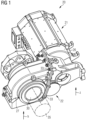
- the single-axis drive 20 has a motor 21.
- the motor 21 is an electric motor which has a stator 31 and a rotor 32.
- the rotor 32 is arranged on a motor shaft 28.
- the single-axis drive 20 also has a gear 22 connected to the motor 21.
- the motor 21 and a Part of the transmission 22 is arranged in a first housing 26.
- the first housing 26 completely surrounds the motor 21.
- the transmission 22 has a large gear 25, which is arranged in a second housing 27.
- the large gear 25 is arranged on a hollow shaft 30.
- the first housing 26 and the second housing 27 are connected to one another in a reversibly detachable manner.
- the first housing 26 and the second housing 27 are connected to one another via a flange connection.
- the first housing 26 and the second housing 27 are screwed together via the flange connection. This means that the first housing 26 and the second housing 27 are connected to one another using screws 33.
- the flange connection forms a parting plane between the first housing 26 and the second housing 27. This means that the first housing 26 and the second housing 27 are connected to one another in the parting plane.
- the single-axle drive 20 can be used in a rail vehicle 34.
- the rail vehicle 34 is, for example, a tram or a subway.
- the single-axle drive 20 can be attached to a wheelset shaft 35 of a wheelset of the rail vehicle 34.
- the hollow shaft 30 is connected to the wheelset shaft 35 of the wheelset.
- the wheelset shaft 35 can be located inside the hollow shaft 30.
- the second housing 27 is thus attached to the wheelset shaft 35 of the wheelset.
- the motor shaft 28 runs parallel to the wheelset shaft 35.
- the first housing 26 is attached to a bogie of the rail vehicle 34.
- the vehicle vertical axis h runs parallel to the Figure 1 shown vertical direction z.
- the parting plane between the first housing 26 and the second housing 27 encloses an angle, which is different from 0°, with the vehicle vertical axis h of the rail vehicle 34.
- the angle between the parting plane and the vehicle vertical axis h is at least 10°.
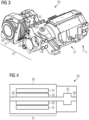
- Figure 2 is the embodiment of the single-axis drive 20 from Figure 1 shown.
- the first housing 26 and the second housing 27 are separated from each other. This is possible by removing the screws 33 between the first housing 26 and the second housing 27.
- the gear 22 has a pinion 23, an intermediate shaft 24 and the large gear 25.
- the motor 21, the pinion 23 and the intermediate shaft 24 are arranged in the first housing 26.
- the pinion 23 and the rotor 32 of the motor 21 are arranged on the motor shaft 28. This means that the motor shaft 28 forms a common shaft for the rotor 32 and the pinion 23.
- the gear 22 has two gear stages.
- the first gear stage is formed by the pinion 23 and the intermediate shaft 24.
- the intermediate shaft 24 is arranged between the pinion 23 and the large gear 25.
- the second gear stage is formed by the Intermediate shaft 24 and the large gear 25 are formed.
- the large gear 25 is arranged in the second housing 27.
- the first housing 26 has an opening 29 in the direction of the second housing 27.
- the second housing 27 has an opening 29 in the direction of the first housing 26.
- the second gear stage can thus be formed in that the gear of the intermediate shaft 24 and the large gear 25 can mesh in the area of the openings 29.
- Figure 3 is also the embodiment of the single-axis drive 20 from Figure 2 shown.
- the single-axis drive 20 is shown from a different direction, so that the interior of the second housing 27 is shown.
- the large gear 25 of the transmission 22 is arranged on the hollow shaft 30.
- the diameter of the large gear 25 is larger than the diameter of the pinion 23.
- a rotation of the rotor 32 can be transmitted to a wheel of a rail vehicle 34 via the motor 21 and the transmission 22.
- the single-axle drive 20 can thus be used to drive a rail vehicle 34.
- the single-axle drive 20 is arranged on the inside of the wheel.
- the single-axle drive 20 can be removed from the rail vehicle 34.
- the first housing 26 and the second housing 27 are thus separated in the second gear stage of the transmission 22.
- the large gear 25 with its bearing remains in the second housing 27 and the intermediate shaft 24 in the first housing 26.
- the center of the second gear stage is given by the connecting axis through the center of the hollow shaft 30 and the intermediate shaft 24. This center encloses an angle of 90° with the parting plane between the first housing 26 and the second housing 27. This enables the first housing 26 to be separated from the second housing 27 and the first housing 26 to be removed from the single-axle drive 20.
- the first housing 26 with the motor 21 can be removed downwards from the rail vehicle 34 in a vertical direction z. This is advantageous because the motor 21 is usually arranged in the lowest position in the rail vehicle 34 and can therefore be easily removed. In addition, no lateral displacement of the first housing 26 is necessary to remove the first housing 26 with the motor 21.
- Figure 4 is a schematic cross section through the single-axis drive 20 according to the embodiment of Figure 1 shown. A cross section through the first housing 26 is shown.
- the motor 21 and the pinion 23 are arranged in the first housing 26.
- the motor 21 has the stator 31 and the rotor 32.
- the stator 31 extends around the rotor 32.
- the rotor 32 is thus arranged in the stator 31.
- the rotor 32 is arranged on the motor shaft 28.
- the pinion 23 is also arranged on the motor shaft 28. The pinion 23 and the rotor 32 are thus connected to one another via the motor shaft 28 and form a component.
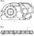
- Figure 5 a single-axis drive 20 according to a further embodiment is shown.
- the intermediate shaft 24 is in Figure 5 arranged in the second housing 27.
- the center of the first gear stage is given by the connecting axis through the centers of the intermediate shaft 24 and the motor shaft 28. This center encloses an angle of 90° with the parting plane between the first housing 26 and the second housing 27.
- the parting plane between the first housing 26 and the second housing 27 encloses an angle of 0° with the vertical axis h of the rail vehicle 34.
- the parting plane thus runs parallel to the vertical direction z. This enables the first housing 26 to be separated from the second housing 27 and the first housing 26 to be removed from the single-axle drive 20.
- the first housing 26 with the motor 21 can be removed downwards from the rail vehicle 34 in a vertical direction z.
- FIG 6 An embodiment of a rail vehicle 34 is shown.
- the rail vehicle 34 comprises one or more single-axle drives 20.
- the single-axle drives 20 can be the ones described in the Figures 1 to 5 shown embodiments of the single-axis drive 20.
Landscapes
- Engineering & Computer Science (AREA)
- Chemical & Material Sciences (AREA)
- Combustion & Propulsion (AREA)
- Transportation (AREA)
- Mechanical Engineering (AREA)
- Arrangement Or Mounting Of Propulsion Units For Vehicles (AREA)
- Connection Of Motors, Electrical Generators, Mechanical Devices, And The Like (AREA)
- Arrangement Of Transmissions (AREA)
- Gear Transmission (AREA)
Description
- Es werden ein Einzelachsantrieb und ein Schienenfahrzeug mit einem solchen Einzelachsantrieb angegeben.
- Einzelachsantriebe für Schienenfahrzeuge weisen üblicherweise einen Motor und ein Getriebe auf. Dabei kann das Großrad des Getriebes an einem Radsatzlager des Schienenfahrzeugs befestigt sein. Der Motor und das Getriebe sind jeweils in einem separaten Gehäuse angeordnet.
- Einzelachsantriebe können insbesondere zum Antrieb von Schienenfahrzeugen verwendet werden. Bei dem Motor des Einzelachsantriebs handelt es sich um einen Elektromotor. Dieser ist über das Getriebe mit einem Rad des Schienenfahrzeugs verbunden. Im Betrieb wird die Drehbewegung des Motors über das Getriebe auf das Rad übertragen.
- Insbesondere werden Einzelachsantriebe in Schienenfahrzeugen wie Straßenbahnen oder U-Bahnen verwendet.
- In der Patentanmeldung
EP 2918471 wird ein Einzelachsantrieb eines Schienenfahrzeugs mit einem Motorgehäuse und einem Getriebegehäuse beschrieben. Eine Verbindung zweier Getriebegehäuseteile über eine lösbare Flanschverbindung in einer Verbindungsebene, in welcher eine Längsachse einer von den Gehäuseteilen umschlossenen Radsatzwelle liegt, ist ebenfalls aus der PatentanmeldungEP 0 571 961 A1 sowie dem GebrauchsmusterDE 68 12 453 U bekannt. - Eine zu lösende Aufgabe besteht darin, einen Einzelachsantrieb, der effizient betrieben werden kann, anzugeben.
- Diese Aufgabe wird mit einem Einzelachsantrieb gemäß Anspruch 1 gelöst.
- Der Einzelachsantrieb umfasst einen Motor, ein mit dem Motor verbundenes zweistufiges Getriebe, welches ein Ritzel, eine Zwischenwelle und ein Großrad aufweist, wobei das Ritzel und die Zwischenwelle eine erste Getriebestufe und die Zwischenwelle und das Großrad eine zweite Getriebestufe bilden, ein erstes Gehäuse, und ein zweites Gehäuse, wobei der Motor und das Ritzel im ersten Gehäuse angeordnet sind, das Großrad im zweiten Gehäuse angeordnet ist, die Zwischenwelle im ersten Gehäuse angeordnet ist, und das Ritzel und ein Rotor des Motors auf einer Motorwelle angeordnet sind.
- Der Motor des Einzelachsantriebs ist ein Elektromotor. Somit weist der Motor einen Stator und einen beweglich zum Stator gelagerten Rotor auf. Der Rotor ist auf der Motorwelle angeordnet. Das Getriebe weist zwei Getriebestufen auf. Die erste Getriebestufe wird durch das Ritzel und die Zwischenwelle gebildet. Die zweite Getriebestufe wird durch die Zwischenwelle und das Großrad gebildet. Bei dem Ritzel und dem Großrad handelt es sich insbesondere um Zahnräder. Auf der Zwischenwelle ist ebenfalls ein Zahnrad angeordnet. Der Motor und das Ritzel sind insbesondere vollständig im ersten Gehäuse angeordnet. Somit sind der Motor und das Ritzel in einem gemeinsamen Gehäuse angeordnet. Das Großrad ist vollständig im zweiten Gehäuse angeordnet.
- Dass das Ritzel und der Rotor auf der Motorwelle angeordnet sind, bedeutet, dass das Ritzel und der Rotor gemeinsam gelagert sind. Das Ritzel und der Rotor sind über die Motorwelle miteinander verbunden. Somit bilden das Ritzel und der Rotor mit der Motorwelle ein Bauteil.
- Der Einzelachsantrieb weist den Vorteil auf, dass keine Kupplung zwischen dem Motor und dem Getriebe benötigt wird. Der Rotor und das Ritzel sind beide auf der Motorwelle angeordnet. Somit wird die Bewegung des Rotors direkt auf das Ritzel übertragen. Da keine Kupplung benötigt wird, ist der Aufbau des Einzelachsantriebs insgesamt besonderes kompakt. Außerdem werden mindestens 10 % des Gesamtgewichts eingespart. Des Weiteren sind die Kosten der Herstellung, der Montage und der Wartung reduziert.
- Da der Motor und ein Teil des Getriebes in einem gemeinsamen Gehäuse, nämlich dem ersten Gehäuse, angeordnet sind, ist der Motor vereinfacht aus dem Einzelachsantrieb ausbaubar. Beispielsweise ist die Lagerung des Rotors vollständig im ersten Gehäuse enthalten. Das bedeutet, insbesondere die Motorwelle ist vollständig im ersten Gehäuse enthalten. Für einen Ausbau des Motors aus dem Einzelachsantrieb ist es daher nicht nötig, den Rotor abzustützen, da die Zentrierung des Rotors erhalten bleibt. Außerdem kann der Motor auch im ausgebauten Zustand einfach getestet und überprüft werden. Dazu wird vorteilhafterweise kein Prüfadapter benötigt. Des Weiteren besteht beim Ausbau des Motors keine Verschmutzungsgefahr, da der Motor beim Ausbau eine geschlossene Einheit im ersten Gehäuse bleibt. Die Vermeidung einer Verschmutzung des Rotors ist insbesondere bei einem Rotor mit Permanentmagneten vorteilhaft.
- Da der Motor und ein Teil des Getriebes beide im ersten Gehäuse angeordnet sind, kann der Einzelachsantrieb mit einer höheren Fertigungsgenauigkeit hergestellt werden. Dies ermöglicht vorteilhafterweise eine höhere Laufruhe.
- Das erste Gehäuse und das zweite Gehäuse sind reversibel lösbar miteinander verbunden. Zum Beispiel sind das erste Gehäuse und das zweite Gehäuse durch Schrauben reversibel lösbar miteinander verbunden. Das bedeutet, das erste Gehäuse und das zweite Gehäuse können voneinander getrennt und wieder miteinander verbunden werden, ohne diese zu zerstören. Dies ermöglicht einen besonders einfachen Ausbau des ersten Gehäuses mit dem Motor.
- Gemäß zumindest einer Ausführungsform des Einzelachsantriebs, sind das erste Gehäuse und das zweite Gehäuse über eine Flanschverbindung miteinander verbunden. Eine Flanschverbindung ermöglicht eine stabile und dichte Verbindung zwischen dem ersten Gehäuse und dem zweiten Gehäuse.
- Gemäß zumindest einer Ausführungsform des Einzelachsantriebs, ist der Einzelachsantrieb dazu ausgelegt in einem Schienenfahrzeug verwendet zu werden.
- Das erste Gehäuse umgibt den Motor insbesondere vollständig. Somit ist der Motor im ersten Gehäuse vor Umwelteinflüssen geschützt.
- Gemäß zumindest einer Ausführungsform des Einzelachsantriebs, weist das erste Gehäuse eine Öffnung in Richtung des zweiten Gehäuses auf. Über die Öffnung wird das erste Gehäuse mit dem zweiten Gehäuse verbunden.
- Gemäß zumindest einer Ausführungsform des Einzelachsantriebs, weist das zweite Gehäuse eine Öffnung in Richtung des ersten Gehäuses auf. Über die Öffnung wird das zweite Gehäuse mit dem ersten Gehäuse verbunden.
- Es wird außerdem ein Schienenfahrzeug, das den Einzelachsantrieb und eine Fahrzeughochachse umfasst, angegeben. Insbesondere kann das Schienenfahrzeug mehrere Einzelachsantriebe aufweisen.
- Gemäß zumindest einer Ausführungsform des Schienenfahrzeugs schließt die Trennebene zwischen dem ersten Gehäuse und dem zweiten Gehäuse einen Winkel, der verschieden von Null Grad ist, mit der Fahrzeughochachse des Schienenfahrzeugs ein. In diesem Fall ist die Zwischenwelle im ersten Gehäuse angeordnet. Das erste Gehäuse mit dem Motor kann somit einfach aus dem Schienenfahrzeug ausgebaut werden.
- Gemäß zumindest einer Ausführungsform des Schienenfahrzeugs schließt die Trennebene zwischen dem ersten Gehäuse und dem zweiten Gehäuse einen Winkel von Null Grad mit der Fahrzeughochachse des Schienenfahrzeugs ein. In diesem Fall ist die Zwischenwelle im zweiten Gehäuse angeordnet. Das erste Gehäuse mit dem Motor kann in diesem Fall einfach aus dem Schienenfahrzeug ausgebaut werden.
- Gemäß zumindest einer Ausführungsform des Schienenfahrzeugs verläuft die Motorwelle parallel zu einer Radsatzwelle. Somit kann der Motor platzsparend neben der Radsatzwelle angeordnet sein.
- Gemäß zumindest einer Ausführungsform des Schienenfahrzeugs ist das zweite Gehäuse an einer Radsatzwelle eines Radsatzes befestigt.
- Die oben genannten Eigenschaften, Merkmale und Vorteile der Erfindung und die Art und Weise, wie diese erreicht werden, werden durch die folgende Beschreibung der Ausführungsbeispiele der Erfindung in Verbindung mit den entsprechenden Figuren weitergehend erläutert, wobei
-
Figur 1 einen Einzelachsantrieb gemäß einem Ausführungsbeispiel, - die
Figuren 2 und3 den Einzelachsantrieb im geöffneten Zustand, -
Figur 4 einen schematischen Querschnitt durch das Ausführungsbeispiel des Einzelachsantriebs, -
Figur 5 einen Einzelachsantrieb gemäß einem weiteren Ausführungsbeispiel, und -
Figur 6 ein Schienenfahrzeug gemäß einem Ausführungsbeispiel zeigen. - In
Figur 1 ist ein Einzelachsantrieb 20 gemäß einem Ausführungsbeispiel gezeigt. Der Einzelachsantrieb 20 weist einen Motor 21 auf. Bei dem Motor 21 handelt es sich um einen Elektromotor, welcher einen Stator 31 und einen Rotor 32 aufweist. Der Rotor 32 ist auf einer Motorwelle 28 angeordnet. Der Einzelachsantrieb 20 weist weiter ein mit dem Motor 21 verbundenes Getriebe 22 auf. Der Motor 21 und ein Teil des Getriebes 22 sind in einem ersten Gehäuse 26 angeordnet. Das erste Gehäuse 26 umgibt den Motor 21 vollständig. Das Getriebe 22 weist ein Großrad 25 auf, welches in einem zweiten Gehäuse 27 angeordnet ist. Das Großrad 25 ist auf einer Hohlwelle 30 angeordnet. - Das erste Gehäuse 26 und das zweite Gehäuse 27 sind reversibel lösbar miteinander verbunden. Dazu sind das erste Gehäuse 26 und das zweite Gehäuse 27 über eine Flanschverbindung miteinander verbunden. Über die Flanschverbindung sind das erste Gehäuse 26 und das zweite Gehäuse 27 miteinander verschraubt. Das bedeutet, das erste Gehäuse 26 und das zweite Gehäuse 27 sind mithilfe von Schrauben 33 miteinander verbunden.
- Durch die Flanschverbindung wird eine Trennebene zwischen dem ersten Gehäuse 26 und dem zweiten Gehäuse 27 geformt. Das bedeutet, dass das erste Gehäuse 26 und das zweite Gehäuse 27 in der Trennebene miteinander verbunden sind. Der Einzelachsantrieb 20 kann in einem Schienenfahrzeug 34 verwendet werden. Bei dem Schienenfahrzeug 34 handelt es sich zum Beispiel um eine Straßenbahn oder um eine U-Bahn. Der Einzelachsantrieb 20 kann dazu an einer Radsatzwelle 35 eines Radsatzes des Schienenfahrzeugs 34 befestigt sein. Zum Beispiel ist die Hohlwelle 30 mit der Radsatzwelle 35 des Radsatzes verbunden. Die Radsatzwelle 35 kann sich im Innern der Hohlwelle 30 befinden. Somit ist das zweite Gehäuse 27 an der Radsatzwelle 35 des Radsatzes befestigt. In diesem Fall verläuft die Motorwelle 28 parallel zur Radsatzwelle 35.
- Da lediglich das zweite Gehäuse 27 direkt an der Radsatzwelle 35 befestigt ist, jedoch nicht das erste Gehäuse 26, sind der Ein- und Ausbau und die Handhabung der Radsatzwelle 35 vereinfacht. Das erste Gehäuse 26 ist an einem Drehgestell des Schienenfahrzeugs 34 befestigt.
- Wenn der Einzelachsantrieb 20 in das Schienenfahrzeug 34 eingebaut ist, verläuft die Fahrzeughochachse h parallel zu der in
Figur 1 gezeigten vertikalen Richtung z. Die Trennebene zwischen dem ersten Gehäuse 26 und dem zweiten Gehäuse 27 schließt einen Winkel, der verschieden von 0° ist, mit der Fahrzeughochachse h des Schienenfahrzeugs 34 ein. Beispielsweise beträgt der Winkel zwischen der Trennebene und der Fahrzeughochachse h mindestens 10°. - In
Figur 2 ist das Ausführungsbeispiel des Einzelachsantriebs 20 ausFigur 1 gezeigt. Dabei sind das erste Gehäuse 26 und das zweite Gehäuse 27 voneinander getrennt. Dies ist durch das Entfernen der Schrauben 33 zwischen dem ersten Gehäuse 26 und dem zweiten Gehäuse 27 möglich. - Das Getriebe 22 weist ein Ritzel 23, eine Zwischenwelle 24 und das Großrad 25 auf. Der Motor 21, das Ritzel 23 und die Zwischenwelle 24 sind im ersten Gehäuse 26 angeordnet. Das Ritzel 23 und der Rotor 32 des Motors 21 sind auf der Motorwelle 28 angeordnet. Das bedeutet, die Motorwelle 28 bildet eine gemeinsame Welle für den Rotor 32 und das Ritzel 23.
- Das Getriebe 22 weist zwei Getriebestufen auf. Die erste Getriebestufe wird durch das Ritzel 23 und die Zwischenwelle 24 gebildet. Somit sind das Ritzel 23 und die Zwischenwelle 24 nebeneinander im ersten Gehäuse 26 angeordnet. Die Zwischenwelle 24 ist zwischen dem Ritzel 23 und dem Großrad 25 angeordnet. Die zweite Getriebestufe wird durch die Zwischenwelle 24 und das Großrad 25 gebildet. Dabei ist das Großrad 25 im zweiten Gehäuse 27 angeordnet.
- Das erste Gehäuse 26 weist eine Öffnung 29 in Richtung des zweiten Gehäuses 27 auf. Außerdem weist das zweite Gehäuse 27 eine Öffnung 29 in Richtung des ersten Gehäuse 26 auf. Somit kann die zweite Getriebestufe dadurch gebildet werden, dass das Zahnrad der Zwischenwelle 24 und das Großrad 25 im Bereich der Öffnungen 29 ineinandergreifen können.
- In
Figur 3 ist ebenfalls das Ausführungsbeispiel des Einzelachsantriebs 20 ausFigur 2 gezeigt. Dabei ist der Einzelachsantrieb 20 aus einer anderen Richtung gezeigt, so dass das Innere des zweiten Gehäuses 27 gezeigt ist. - Das Großrad 25 des Getriebes 22 ist auf der Hohlwelle 30 angeordnet. Der Durchmesser des Großrads 25 ist größer als der Durchmesser des Ritzels 23. Über den Motor 21 und das Getriebe 22 kann eine Rotation des Rotors 32 auf ein Rad eines Schienenfahrzeugs 34 übertragen werden. Somit kann der Einzelachsantrieb 20 zum Antrieb eines Schienenfahrzeugs 34 verwendet werden. Dabei ist der Einzelachsantrieb 20 an der Innenseite des Rads angeordnet.
- Durch das Öffnen der Schrauben 33 zwischen dem ersten Gehäuse 26 und dem zweiten Gehäuse 27 kann der Einzelachsantrieb 20 aus dem Schienenfahrzeug 34 ausgebaut werden. Somit erfolgt die Trennung des ersten Gehäuses 26 und des zweiten Gehäuses 27 in der zweiten Getriebestufe des Getriebes 22. Bei der Trennung verbleibt das Großrad 25 mit dessen Lagerung im zweiten Gehäuse 27 und die Zwischenwelle 24 im ersten Gehäuse 26.
- Die Zentrale der zweiten Getriebestufe ist durch die Verbindungsachse durch den Mittelpunkt der Hohlwelle 30 und der Zwischenwelle 24 gegeben. Diese Zentrale schließt einen Winkel von 90° mit der Trennebene zwischen dem ersten Gehäuse 26 und dem zweiten Gehäuse 27 ein. Dies ermöglicht die Trennung des ersten Gehäuses 26 vom zweiten Gehäuse 27 und den Ausbau des ersten Gehäuses 26 aus dem Einzelachsantrieb 20. Dabei kann das erste Gehäuse 26 mit dem Motor 21 in einer vertikalen Richtung z nach unten aus dem Schienenfahrzeug 34 ausgebaut werden. Dies ist vorteilhaft, da der Motor 21 üblicherweise an unterster Position im Schienenfahrzeug 34 angeordnet ist und somit einfach ausgebaut werden kann. Außerdem ist zum Ausbau des ersten Gehäuses 26 mit dem Motor 21 keine seitliche Verschiebung des ersten Gehäuses 26 nötig.
- In
Figur 4 ist ein schematischer Querschnitt durch den Einzelachsantrieb 20 gemäß dem Ausführungsbeispiel ausFigur 1 gezeigt. Dabei ist ein Querschnitt durch das erste Gehäuse 26 gezeigt. - Im ersten Gehäuse 26 sind der Motor 21 und das Ritzel 23 angeordnet. Der Motor 21 weist den Stator 31 und den Rotor 32 auf. Der Stator 31 erstreckt sich um den Rotor 32 herum. Somit ist der Rotor 32 im Stator 31 angeordnet. Der Rotor 32 ist auf der Motorwelle 28 angeordnet. Das Ritzel 23 ist ebenfalls auf der Motorwelle 28 angeordnet. Somit sind das Ritzel 23 und der Rotor 32 über die Motorwelle 28 miteinander verbunden und bilden ein Bauteil.
- In
Figur 5 ist ein Einzelachsantrieb 20 gemäß einem weiteren Ausführungsbeispiel gezeigt. Im Unterschied zu dem in denFiguren 1 bis 3 gezeigten Ausführungsbeispiel ist die Zwischenwelle 24 inFigur 5 im zweiten Gehäuse 27 angeordnet. - Somit erfolgt die Trennung des ersten Gehäuses 26 vom zweiten Gehäuse 27 in der ersten Getriebestufe des Getriebes 22.
- Die Zentrale der ersten Getriebestufe ist durch die Verbindungsachse durch die Mittelpunkte der Zwischenwelle 24 und der Motorwelle 28 gegeben. Diese Zentrale schließt einen Winkel von 90° mit der Trennebene zwischen dem ersten Gehäuse 26 und dem zweiten Gehäuse 27 ein. Außerdem schließt die Trennebene zwischen dem ersten Gehäuse 26 und dem zweiten Gehäuse 27 einen Winkel von 0° mit der Fahrzeughochachse h des Schienenfahrzeugs 34 ein. Somit verläuft die Trennebene parallel zur vertikalen Richtung z. Dies ermöglicht die Trennung des ersten Gehäuses 26 vom zweiten Gehäuse 27 und den Ausbau des ersten Gehäuses 26 aus dem Einzelachsantrieb 20. Dabei kann das erste Gehäuse 26 mit dem Motor 21 in einer vertikalen Richtung z nach unten aus dem Schienenfahrzeug 34 ausgebaut werden.
- In
Figur 6 ist ein Ausführungsbeispiel eines Schienenfahrzeugs 34 gezeigt. Das Schienenfahrzeug 34 umfasst einen oder mehrere Einzelachsantriebe 20. Bei den Einzelachsantrieben 20 kann es sich um die in denFiguren 1 bis 5 gezeigten Ausführungsbeispiele des Einzelachsantriebs 20 handeln. - Obwohl die Erfindung anhand von Ausführungsbeispielen detailliert dargestellt und beschrieben wurde, ist die Erfindung nicht auf die offenbarten Ausführungsbeispiele und die darin erläuterten konkreten Merkmalskombinationen beschränkt. Weitere Variationen der Erfindung können von einem Fachmann erhalten werden, ohne den Schutzumfang der angehängten Ansprüchen zu verlassen.
-
- 20:
- Einzelachsantrieb
- 21:
- Motor
- 22:
- Getriebe
- 23:
- Ritzel
- 24:
- Zwischenwelle
- 25:
- Großrad
- 26:
- erstes Gehäuse
- 27:
- zweites Gehäuse
- 28:
- Motorwelle
- 29:
- Öffnung
- 30:
- Hohlwelle
- 31:
- Stator
- 32:
- Rotor
- 33:
- Schraube
- 34:
- Schienenfahrzeug
- 35:
- Radsatzwelle
- h:
- Fahrzeughochachse
- z:
- vertikale Richtung
Claims (10)
- Einzelachsantrieb (20) umfassend:- einen Motor (21),- ein mit dem Motor (21) verbundenes zweistufiges Getriebe (22), welches ein Ritzel (23), eine Zwischenwelle (24) und ein Großrad (25) aufweist, wobei das Ritzel (23) und die Zwischenwelle (24) eine erste Getriebestufe und die Zwischenwelle (24) und das Großrad (25) eine zweite Getriebestufe bilden,- ein erstes Gehäuse (26), und- ein zweites Gehäuse (27), wobei- das Ritzel (23) und ein Rotor (32) des Motors (21) auf einer Motorwelle (28) angeordnet sind,- der Motor (21) im ersten Gehäuse (26) angeordnet ist, und- das Großrad (25) im zweiten Gehäuse (27) angeordnet ist,
dadurch gekennzeichnet, dass- das Ritzel (23) und die Zwischenwelle (24) im ersten Gehäuse (26) angeordnet sind, und- das erste Gehäuse (26) und das zweite Gehäuse (27) reversibel lösbar miteinander verbunden sind. - Einzelachsantrieb (20) gemäß einem der vorherigen Ansprüche, bei dem das erste Gehäuse (26) und das zweite Gehäuse (27) über eine Flanschverbindung miteinander verbunden sind.
- Einzelachsantrieb (20) gemäß einem der vorherigen Ansprüche, welcher dazu ausgelegt ist in einem Schienenfahrzeug (34) verwendet zu werden.
- Einzelachsantrieb (20) gemäß einem der vorherigen Ansprüche, bei dem das erste Gehäuse (26) eine Öffnung (29) in Richtung des zweiten Gehäuses (27) aufweist.
- Einzelachsantrieb (20) gemäß einem der vorherigen Ansprüche, bei dem das zweite Gehäuse (27) eine Öffnung (29) in Richtung des ersten Gehäuses (26) aufweist.
- Schienenfahrzeug (34) umfassend eine Fahrzeughochachse (h) und den Einzelachsantrieb (20) gemäß einem der vorherigen Ansprüche.
- Schienenfahrzeug (34) gemäß Anspruch 6, bei dem die Trennebene zwischen dem ersten Gehäuse (26) und dem zweiten Gehäuse (27) einen Winkel, der verschieden von Null Grad ist, mit der Fahrzeughochachse (h) des Schienenfahrzeugs (34) einschließt.
- Schienenfahrzeug (34) gemäß Anspruch 6, bei dem die Trennebene zwischen dem ersten Gehäuse (26) und dem zweiten Gehäuse (27) einen Winkel von Null Grad mit der Fahrzeughochachse (h) des Schienenfahrzeugs (34) einschließt.
- Schienenfahrzeug gemäß einem der Ansprüche 6 bis 8, bei dem die Motorwelle (28) parallel zu einer Radsatzwelle (35) verläuft.
- Schienenfahrzeug gemäß einem der Ansprüche 6 bis 9, bei dem das zweite Gehäuse (27) an einer Radsatzwelle (35) eines Radsatzes befestigt ist.
Applications Claiming Priority (2)
| Application Number | Priority Date | Filing Date | Title |
|---|---|---|---|
| DE102019211172.6A DE102019211172B4 (de) | 2019-07-26 | 2019-07-26 | Einzelachsantrieb und Schienenfahrzeug |
| PCT/EP2020/068403 WO2021018498A1 (de) | 2019-07-26 | 2020-06-30 | Einzelachsantrieb und schienenfahrzeug |
Publications (2)
| Publication Number | Publication Date |
|---|---|
| EP3980312A1 EP3980312A1 (de) | 2022-04-13 |
| EP3980312B1 true EP3980312B1 (de) | 2025-02-12 |
Family
ID=71607924
Family Applications (1)
| Application Number | Title | Priority Date | Filing Date |
|---|---|---|---|
| EP20739893.4A Active EP3980312B1 (de) | 2019-07-26 | 2020-06-30 | Einzelachsantrieb und schienenfahrzeug |
Country Status (4)
| Country | Link |
|---|---|
| EP (1) | EP3980312B1 (de) |
| DE (1) | DE102019211172B4 (de) |
| ES (1) | ES3024439T3 (de) |
| WO (1) | WO2021018498A1 (de) |
Families Citing this family (1)
| Publication number | Priority date | Publication date | Assignee | Title |
|---|---|---|---|---|
| CN114789739B (zh) * | 2022-04-14 | 2024-09-20 | 中车青岛四方机车车辆股份有限公司 | 传动机构、转向架及轨道车辆 |
Family Cites Families (6)
| Publication number | Priority date | Publication date | Assignee | Title |
|---|---|---|---|---|
| DE6812453U (de) * | 1968-12-20 | 1969-04-03 | Bbc Brown Boveri & Cie | Antriebsanordnung fuer zwei- bzw. dreiachsige drehgestelle |
| IT1257195B (it) * | 1992-05-26 | 1996-01-10 | Carrello per veicoli ferrotranviari con motori di trazione e riduttorisospesi al telaio. | |
| FR2803572B1 (fr) * | 2000-01-12 | 2002-02-22 | Alstom | Bogie moteur pour vehicule ferroviaire et vehicule ferroviaire pourvu d'un tel bogie |
| ES2851327T3 (es) * | 2014-03-10 | 2021-09-06 | Siemens Mobility GmbH | Accionamiento de un solo eje de un vehículo ferroviario |
| DE102016213998A1 (de) * | 2016-07-29 | 2018-02-01 | Voith Patent Gmbh | Radsatzgetriebe und Verfahren zur Montage |
| EP3707401B1 (de) * | 2017-11-10 | 2022-12-28 | Süddeutsche Gelenkscheibenfabrik GmbH & Co. KG | Kupplungsvorrichtung |
-
2019
- 2019-07-26 DE DE102019211172.6A patent/DE102019211172B4/de not_active Expired - Fee Related
-
2020
- 2020-06-30 WO PCT/EP2020/068403 patent/WO2021018498A1/de not_active Ceased
- 2020-06-30 ES ES20739893T patent/ES3024439T3/es active Active
- 2020-06-30 EP EP20739893.4A patent/EP3980312B1/de active Active
Also Published As
| Publication number | Publication date |
|---|---|
| DE102019211172A1 (de) | 2021-01-28 |
| DE102019211172B4 (de) | 2021-02-25 |
| WO2021018498A1 (de) | 2021-02-04 |
| EP3980312A1 (de) | 2022-04-13 |
| ES3024439T3 (en) | 2025-06-04 |
Similar Documents
| Publication | Publication Date | Title |
|---|---|---|
| EP3310636B1 (de) | Antriebsanordnung für schienenfahrzeug, schienenfahrzeug mit antriebsanordnung sowie verfahren zum herstellen der antriebsanordnung und des schienenfahrzeugs | |
| EP2776299B1 (de) | Getriebeeinheit | |
| DE2657575A1 (de) | Parallelwellenantrieb | |
| AT405390B (de) | Elektromotorischer radnabenantrieb für ein fahrzeugrad | |
| EP3768561B1 (de) | Bremsvorrichtung | |
| DE102019211172B4 (de) | Einzelachsantrieb und Schienenfahrzeug | |
| DE3926878C2 (de) | ||
| EP1774197B1 (de) | Antriebsanordnung für ein kraftfahrzeug, insbesondere einen niederflurbus | |
| EP0052244B1 (de) | Drehgestell für Schienenfahrzeuge, wie Strassenbahnen | |
| DE102015222125A1 (de) | Antriebsanordnung für ein Schienenfahrzeug, Schienenfahrzeug mit der Antriebsanordnung und Verfahren zur Herstellung | |
| EP0542173A1 (de) | Antriebseinheit für Schienentriebfahrzeuge | |
| DE3704454A1 (de) | Achsgetriebe | |
| DE10032707A1 (de) | Antriebseinheit zum Antrieb mindestens einer Radantriebswelle, insbesondere einer Radsatzwelle | |
| DE102019206236A1 (de) | Gehäuse mit zwei zueinander ausgerichteten Gehäuseteilen für eine Baueinheit eines Fahrzeugantriebsstranges | |
| EP0310763B1 (de) | Lagerung einer mindestens ein Zahnrad tragenden Getriebewelle | |
| EP0878368B1 (de) | Antriebseinheit für Schienenfahrzeuge | |
| EP0718170B1 (de) | Fahrwerk für Schienenfahrzeuge | |
| DE202017102027U1 (de) | Getriebeeinheit für ein Kraftfahrzeug | |
| WO2016184566A1 (de) | Scheibenwischerantrieb einer scheibenwischervorrichtung eines schienenfahrzeugs | |
| EP3380380B1 (de) | Doppelachsantrieb | |
| DE19602119C1 (de) | Einzelradantrieb für ein elektrisch angetriebenes Fahrzeug | |
| EP3686076A1 (de) | Getriebegehäuse und anordnung zur abstützung eines getriebes | |
| DE102019214515A1 (de) | Antriebsstrang für ein Kraftfahrzeug | |
| EP4297986B1 (de) | Antriebsvorrichtung für eine fahrzeugachse | |
| DE102011003324A1 (de) | Flanschverbindung zwischen einem Getriebegehäuse und einem Motorschwungradgehäuse eines Kraftfahrzeugs |
Legal Events
| Date | Code | Title | Description |
|---|---|---|---|
| STAA | Information on the status of an ep patent application or granted ep patent |
Free format text: STATUS: UNKNOWN |
|
| STAA | Information on the status of an ep patent application or granted ep patent |
Free format text: STATUS: THE INTERNATIONAL PUBLICATION HAS BEEN MADE |
|
| PUAI | Public reference made under article 153(3) epc to a published international application that has entered the european phase |
Free format text: ORIGINAL CODE: 0009012 |
|
| STAA | Information on the status of an ep patent application or granted ep patent |
Free format text: STATUS: REQUEST FOR EXAMINATION WAS MADE |
|
| 17P | Request for examination filed |
Effective date: 20220107 |
|
| AK | Designated contracting states |
Kind code of ref document: A1 Designated state(s): AL AT BE BG CH CY CZ DE DK EE ES FI FR GB GR HR HU IE IS IT LI LT LU LV MC MK MT NL NO PL PT RO RS SE SI SK SM TR |
|
| DAV | Request for validation of the european patent (deleted) | ||
| DAX | Request for extension of the european patent (deleted) | ||
| STAA | Information on the status of an ep patent application or granted ep patent |
Free format text: STATUS: EXAMINATION IS IN PROGRESS |
|
| 17Q | First examination report despatched |
Effective date: 20230808 |
|
| GRAP | Despatch of communication of intention to grant a patent |
Free format text: ORIGINAL CODE: EPIDOSNIGR1 |
|
| STAA | Information on the status of an ep patent application or granted ep patent |
Free format text: STATUS: GRANT OF PATENT IS INTENDED |
|
| INTG | Intention to grant announced |
Effective date: 20241023 |
|
| GRAS | Grant fee paid |
Free format text: ORIGINAL CODE: EPIDOSNIGR3 |
|
| GRAA | (expected) grant |
Free format text: ORIGINAL CODE: 0009210 |
|
| STAA | Information on the status of an ep patent application or granted ep patent |
Free format text: STATUS: THE PATENT HAS BEEN GRANTED |
|
| AK | Designated contracting states |
Kind code of ref document: B1 Designated state(s): AL AT BE BG CH CY CZ DE DK EE ES FI FR GB GR HR HU IE IS IT LI LT LU LV MC MK MT NL NO PL PT RO RS SE SI SK SM TR |
|
| REG | Reference to a national code |
Ref country code: GB Ref legal event code: FG4D Free format text: NOT ENGLISH |
|
| REG | Reference to a national code |
Ref country code: CH Ref legal event code: EP |
|
| REG | Reference to a national code |
Ref country code: DE Ref legal event code: R096 Ref document number: 502020010380 Country of ref document: DE |
|
| REG | Reference to a national code |
Ref country code: IE Ref legal event code: FG4D Free format text: LANGUAGE OF EP DOCUMENT: GERMAN |
|
| REG | Reference to a national code |
Ref country code: ES Ref legal event code: FG2A Ref document number: 3024439 Country of ref document: ES Kind code of ref document: T3 Effective date: 20250604 |
|
| REG | Reference to a national code |
Ref country code: NL Ref legal event code: MP Effective date: 20250212 |
|
| PG25 | Lapsed in a contracting state [announced via postgrant information from national office to epo] |
Ref country code: RS Free format text: LAPSE BECAUSE OF FAILURE TO SUBMIT A TRANSLATION OF THE DESCRIPTION OR TO PAY THE FEE WITHIN THE PRESCRIBED TIME-LIMIT Effective date: 20250512 |
|
| PG25 | Lapsed in a contracting state [announced via postgrant information from national office to epo] |
Ref country code: FI Free format text: LAPSE BECAUSE OF FAILURE TO SUBMIT A TRANSLATION OF THE DESCRIPTION OR TO PAY THE FEE WITHIN THE PRESCRIBED TIME-LIMIT Effective date: 20250212 |
|
| PG25 | Lapsed in a contracting state [announced via postgrant information from national office to epo] |
Ref country code: PL Free format text: LAPSE BECAUSE OF FAILURE TO SUBMIT A TRANSLATION OF THE DESCRIPTION OR TO PAY THE FEE WITHIN THE PRESCRIBED TIME-LIMIT Effective date: 20250212 |
|
| REG | Reference to a national code |
Ref country code: LT Ref legal event code: MG9D |
|
| PG25 | Lapsed in a contracting state [announced via postgrant information from national office to epo] |
Ref country code: NO Free format text: LAPSE BECAUSE OF FAILURE TO SUBMIT A TRANSLATION OF THE DESCRIPTION OR TO PAY THE FEE WITHIN THE PRESCRIBED TIME-LIMIT Effective date: 20250512 Ref country code: IS Free format text: LAPSE BECAUSE OF FAILURE TO SUBMIT A TRANSLATION OF THE DESCRIPTION OR TO PAY THE FEE WITHIN THE PRESCRIBED TIME-LIMIT Effective date: 20250612 |
|
| PG25 | Lapsed in a contracting state [announced via postgrant information from national office to epo] |
Ref country code: NL Free format text: LAPSE BECAUSE OF FAILURE TO SUBMIT A TRANSLATION OF THE DESCRIPTION OR TO PAY THE FEE WITHIN THE PRESCRIBED TIME-LIMIT Effective date: 20250212 |
|
| PG25 | Lapsed in a contracting state [announced via postgrant information from national office to epo] |
Ref country code: HR Free format text: LAPSE BECAUSE OF FAILURE TO SUBMIT A TRANSLATION OF THE DESCRIPTION OR TO PAY THE FEE WITHIN THE PRESCRIBED TIME-LIMIT Effective date: 20250212 |
|
| PG25 | Lapsed in a contracting state [announced via postgrant information from national office to epo] |
Ref country code: PT Free format text: LAPSE BECAUSE OF FAILURE TO SUBMIT A TRANSLATION OF THE DESCRIPTION OR TO PAY THE FEE WITHIN THE PRESCRIBED TIME-LIMIT Effective date: 20250612 Ref country code: LV Free format text: LAPSE BECAUSE OF FAILURE TO SUBMIT A TRANSLATION OF THE DESCRIPTION OR TO PAY THE FEE WITHIN THE PRESCRIBED TIME-LIMIT Effective date: 20250212 |
|
| PG25 | Lapsed in a contracting state [announced via postgrant information from national office to epo] |
Ref country code: GR Free format text: LAPSE BECAUSE OF FAILURE TO SUBMIT A TRANSLATION OF THE DESCRIPTION OR TO PAY THE FEE WITHIN THE PRESCRIBED TIME-LIMIT Effective date: 20250513 Ref country code: BG Free format text: LAPSE BECAUSE OF FAILURE TO SUBMIT A TRANSLATION OF THE DESCRIPTION OR TO PAY THE FEE WITHIN THE PRESCRIBED TIME-LIMIT Effective date: 20250212 |
|
| REG | Reference to a national code |
Ref country code: DE Ref legal event code: R081 Ref document number: 502020010380 Country of ref document: DE Owner name: SIEMENS MOBILITY GMBH, DE Free format text: FORMER OWNER: SIEMENS MOBILITY GMBH, 81739 MUENCHEN, DE |
|
| PG25 | Lapsed in a contracting state [announced via postgrant information from national office to epo] |
Ref country code: SE Free format text: LAPSE BECAUSE OF FAILURE TO SUBMIT A TRANSLATION OF THE DESCRIPTION OR TO PAY THE FEE WITHIN THE PRESCRIBED TIME-LIMIT Effective date: 20250212 |
|
| PG25 | Lapsed in a contracting state [announced via postgrant information from national office to epo] |
Ref country code: SM Free format text: LAPSE BECAUSE OF FAILURE TO SUBMIT A TRANSLATION OF THE DESCRIPTION OR TO PAY THE FEE WITHIN THE PRESCRIBED TIME-LIMIT Effective date: 20250212 |
|
| RAP4 | Party data changed (patent owner data changed or rights of a patent transferred) |
Owner name: SIEMENS MOBILITY GMBH |
|
| PGFP | Annual fee paid to national office [announced via postgrant information from national office to epo] |
Ref country code: ES Payment date: 20250923 Year of fee payment: 6 |
|
| PG25 | Lapsed in a contracting state [announced via postgrant information from national office to epo] |
Ref country code: DK Free format text: LAPSE BECAUSE OF FAILURE TO SUBMIT A TRANSLATION OF THE DESCRIPTION OR TO PAY THE FEE WITHIN THE PRESCRIBED TIME-LIMIT Effective date: 20250212 |
|
| PGFP | Annual fee paid to national office [announced via postgrant information from national office to epo] |
Ref country code: DE Payment date: 20250820 Year of fee payment: 6 |
|
| PGFP | Annual fee paid to national office [announced via postgrant information from national office to epo] |
Ref country code: GB Payment date: 20250710 Year of fee payment: 6 |
|
| PG25 | Lapsed in a contracting state [announced via postgrant information from national office to epo] |
Ref country code: EE Free format text: LAPSE BECAUSE OF FAILURE TO SUBMIT A TRANSLATION OF THE DESCRIPTION OR TO PAY THE FEE WITHIN THE PRESCRIBED TIME-LIMIT Effective date: 20250212 |
|
| PG25 | Lapsed in a contracting state [announced via postgrant information from national office to epo] |
Ref country code: RO Free format text: LAPSE BECAUSE OF FAILURE TO SUBMIT A TRANSLATION OF THE DESCRIPTION OR TO PAY THE FEE WITHIN THE PRESCRIBED TIME-LIMIT Effective date: 20250212 |
|
| PG25 | Lapsed in a contracting state [announced via postgrant information from national office to epo] |
Ref country code: SK Free format text: LAPSE BECAUSE OF FAILURE TO SUBMIT A TRANSLATION OF THE DESCRIPTION OR TO PAY THE FEE WITHIN THE PRESCRIBED TIME-LIMIT Effective date: 20250212 |
|
| REG | Reference to a national code |
Ref country code: DE Ref legal event code: R097 Ref document number: 502020010380 Country of ref document: DE |
|
| PLBE | No opposition filed within time limit |
Free format text: ORIGINAL CODE: 0009261 |
|
| STAA | Information on the status of an ep patent application or granted ep patent |
Free format text: STATUS: NO OPPOSITION FILED WITHIN TIME LIMIT |
|
| REG | Reference to a national code |
Ref country code: CH Ref legal event code: L10 Free format text: ST27 STATUS EVENT CODE: U-0-0-L10-L00 (AS PROVIDED BY THE NATIONAL OFFICE) Effective date: 20251224 |
|
| 26N | No opposition filed |
Effective date: 20251113 |
|
| REG | Reference to a national code |
Ref country code: CH Ref legal event code: H13 Free format text: ST27 STATUS EVENT CODE: U-0-0-H10-H13 (AS PROVIDED BY THE NATIONAL OFFICE) Effective date: 20260127 |
|
| PG25 | Lapsed in a contracting state [announced via postgrant information from national office to epo] |
Ref country code: MC Free format text: LAPSE BECAUSE OF FAILURE TO SUBMIT A TRANSLATION OF THE DESCRIPTION OR TO PAY THE FEE WITHIN THE PRESCRIBED TIME-LIMIT Effective date: 20250212 |
|
| PG25 | Lapsed in a contracting state [announced via postgrant information from national office to epo] |
Ref country code: LU Free format text: LAPSE BECAUSE OF NON-PAYMENT OF DUE FEES Effective date: 20250630 |
|
| REG | Reference to a national code |
Ref country code: BE Ref legal event code: MM Effective date: 20250630 |
|
| PG25 | Lapsed in a contracting state [announced via postgrant information from national office to epo] |
Ref country code: IE Free format text: LAPSE BECAUSE OF NON-PAYMENT OF DUE FEES Effective date: 20250630 |
|
| PG25 | Lapsed in a contracting state [announced via postgrant information from national office to epo] |
Ref country code: BE Free format text: LAPSE BECAUSE OF NON-PAYMENT OF DUE FEES Effective date: 20250630 |
|
| PG25 | Lapsed in a contracting state [announced via postgrant information from national office to epo] |
Ref country code: CH Free format text: LAPSE BECAUSE OF NON-PAYMENT OF DUE FEES Effective date: 20250630 |
|
| PG25 | Lapsed in a contracting state [announced via postgrant information from national office to epo] |
Ref country code: LT Free format text: LAPSE BECAUSE OF FAILURE TO SUBMIT A TRANSLATION OF THE DESCRIPTION OR TO PAY THE FEE WITHIN THE PRESCRIBED TIME-LIMIT Effective date: 20250212 |
|
| PGFP | Annual fee paid to national office [announced via postgrant information from national office to epo] |
Ref country code: IT Payment date: 20260610 Year of fee payment: 7 |
|
| PGFP | Annual fee paid to national office [announced via postgrant information from national office to epo] |
Ref country code: AT Payment date: 20260508 Year of fee payment: 7 |
|
| PGFP | Annual fee paid to national office [announced via postgrant information from national office to epo] |
Ref country code: CZ Payment date: 20260626 Year of fee payment: 7 |
|
| PGFP | Annual fee paid to national office [announced via postgrant information from national office to epo] |
Ref country code: FR Payment date: 20260616 Year of fee payment: 7 |
|
| PG25 | Lapsed in a contracting state [announced via postgrant information from national office to epo] |
Ref country code: CY Free format text: LAPSE BECAUSE OF FAILURE TO SUBMIT A TRANSLATION OF THE DESCRIPTION OR TO PAY THE FEE WITHIN THE PRESCRIBED TIME-LIMIT Effective date: 20250212 |