EP3980286B1 - Battery load mechanism for electric lhd mining machine - Google Patents
Battery load mechanism for electric lhd mining machine Download PDFInfo
- Publication number
- EP3980286B1 EP3980286B1 EP20818548.8A EP20818548A EP3980286B1 EP 3980286 B1 EP3980286 B1 EP 3980286B1 EP 20818548 A EP20818548 A EP 20818548A EP 3980286 B1 EP3980286 B1 EP 3980286B1
- Authority
- EP
- European Patent Office
- Prior art keywords
- power source
- vehicle
- replaceable power
- lifting portion
- horizontal shaft
- Prior art date
- Legal status (The legal status is an assumption and is not a legal conclusion. Google has not performed a legal analysis and makes no representation as to the accuracy of the status listed.)
- Active
Links
Images


Classifications
-
- B—PERFORMING OPERATIONS; TRANSPORTING
- B60—VEHICLES IN GENERAL
- B60L—PROPULSION OF ELECTRICALLY-PROPELLED VEHICLES; SUPPLYING ELECTRIC POWER FOR AUXILIARY EQUIPMENT OF ELECTRICALLY-PROPELLED VEHICLES; ELECTRODYNAMIC BRAKE SYSTEMS FOR VEHICLES IN GENERAL; MAGNETIC SUSPENSION OR LEVITATION FOR VEHICLES; MONITORING OPERATING VARIABLES OF ELECTRICALLY-PROPELLED VEHICLES; ELECTRIC SAFETY DEVICES FOR ELECTRICALLY-PROPELLED VEHICLES
- B60L53/00—Methods of charging batteries, specially adapted for electric vehicles; Charging stations or on-board charging equipment therefor; Exchange of energy storage elements in electric vehicles
- B60L53/80—Exchanging energy storage elements, e.g. removable batteries
-
- B—PERFORMING OPERATIONS; TRANSPORTING
- B60—VEHICLES IN GENERAL
- B60K—ARRANGEMENT OR MOUNTING OF PROPULSION UNITS OR OF TRANSMISSIONS IN VEHICLES; ARRANGEMENT OR MOUNTING OF PLURAL DIVERSE PRIME-MOVERS IN VEHICLES; AUXILIARY DRIVES FOR VEHICLES; INSTRUMENTATION OR DASHBOARDS FOR VEHICLES; ARRANGEMENTS IN CONNECTION WITH COOLING, AIR INTAKE, GAS EXHAUST OR FUEL SUPPLY OF PROPULSION UNITS IN VEHICLES
- B60K1/00—Arrangement or mounting of electrical propulsion units
- B60K1/04—Arrangement or mounting of electrical propulsion units of the electric storage means for propulsion
-
- B—PERFORMING OPERATIONS; TRANSPORTING
- B60—VEHICLES IN GENERAL
- B60L—PROPULSION OF ELECTRICALLY-PROPELLED VEHICLES; SUPPLYING ELECTRIC POWER FOR AUXILIARY EQUIPMENT OF ELECTRICALLY-PROPELLED VEHICLES; ELECTRODYNAMIC BRAKE SYSTEMS FOR VEHICLES IN GENERAL; MAGNETIC SUSPENSION OR LEVITATION FOR VEHICLES; MONITORING OPERATING VARIABLES OF ELECTRICALLY-PROPELLED VEHICLES; ELECTRIC SAFETY DEVICES FOR ELECTRICALLY-PROPELLED VEHICLES
- B60L50/00—Electric propulsion with power supplied within the vehicle
- B60L50/50—Electric propulsion with power supplied within the vehicle using propulsion power supplied by batteries or fuel cells
- B60L50/60—Electric propulsion with power supplied within the vehicle using propulsion power supplied by batteries or fuel cells using power supplied by batteries
- B60L50/66—Arrangements of batteries
-
- B—PERFORMING OPERATIONS; TRANSPORTING
- B60—VEHICLES IN GENERAL
- B60K—ARRANGEMENT OR MOUNTING OF PROPULSION UNITS OR OF TRANSMISSIONS IN VEHICLES; ARRANGEMENT OR MOUNTING OF PLURAL DIVERSE PRIME-MOVERS IN VEHICLES; AUXILIARY DRIVES FOR VEHICLES; INSTRUMENTATION OR DASHBOARDS FOR VEHICLES; ARRANGEMENTS IN CONNECTION WITH COOLING, AIR INTAKE, GAS EXHAUST OR FUEL SUPPLY OF PROPULSION UNITS IN VEHICLES
- B60K1/00—Arrangement or mounting of electrical propulsion units
- B60K1/04—Arrangement or mounting of electrical propulsion units of the electric storage means for propulsion
- B60K2001/0405—Arrangement or mounting of electrical propulsion units of the electric storage means for propulsion characterised by their position
- B60K2001/0416—Arrangement in the rear part of the vehicle
-
- B—PERFORMING OPERATIONS; TRANSPORTING
- B60—VEHICLES IN GENERAL
- B60K—ARRANGEMENT OR MOUNTING OF PROPULSION UNITS OR OF TRANSMISSIONS IN VEHICLES; ARRANGEMENT OR MOUNTING OF PLURAL DIVERSE PRIME-MOVERS IN VEHICLES; AUXILIARY DRIVES FOR VEHICLES; INSTRUMENTATION OR DASHBOARDS FOR VEHICLES; ARRANGEMENTS IN CONNECTION WITH COOLING, AIR INTAKE, GAS EXHAUST OR FUEL SUPPLY OF PROPULSION UNITS IN VEHICLES
- B60K1/00—Arrangement or mounting of electrical propulsion units
- B60K1/04—Arrangement or mounting of electrical propulsion units of the electric storage means for propulsion
- B60K2001/0455—Removal or replacement of the energy storages
- B60K2001/0477—Removal or replacement of the energy storages from the back
-
- B—PERFORMING OPERATIONS; TRANSPORTING
- B60—VEHICLES IN GENERAL
- B60L—PROPULSION OF ELECTRICALLY-PROPELLED VEHICLES; SUPPLYING ELECTRIC POWER FOR AUXILIARY EQUIPMENT OF ELECTRICALLY-PROPELLED VEHICLES; ELECTRODYNAMIC BRAKE SYSTEMS FOR VEHICLES IN GENERAL; MAGNETIC SUSPENSION OR LEVITATION FOR VEHICLES; MONITORING OPERATING VARIABLES OF ELECTRICALLY-PROPELLED VEHICLES; ELECTRIC SAFETY DEVICES FOR ELECTRICALLY-PROPELLED VEHICLES
- B60L2200/00—Type of vehicles
- B60L2200/40—Working vehicles
-
- B—PERFORMING OPERATIONS; TRANSPORTING
- B60—VEHICLES IN GENERAL
- B60Y—INDEXING SCHEME RELATING TO ASPECTS CROSS-CUTTING VEHICLE TECHNOLOGY
- B60Y2200/00—Type of vehicle
- B60Y2200/40—Special vehicles
- B60Y2200/41—Construction vehicles, e.g. graders, excavators
- B60Y2200/411—Bulldozers, Graders
-
- B—PERFORMING OPERATIONS; TRANSPORTING
- B60—VEHICLES IN GENERAL
- B60Y—INDEXING SCHEME RELATING TO ASPECTS CROSS-CUTTING VEHICLE TECHNOLOGY
- B60Y2200/00—Type of vehicle
- B60Y2200/40—Special vehicles
- B60Y2200/41—Construction vehicles, e.g. graders, excavators
- B60Y2200/417—Articulated frame vehicles
-
- Y—GENERAL TAGGING OF NEW TECHNOLOGICAL DEVELOPMENTS; GENERAL TAGGING OF CROSS-SECTIONAL TECHNOLOGIES SPANNING OVER SEVERAL SECTIONS OF THE IPC; TECHNICAL SUBJECTS COVERED BY FORMER USPC CROSS-REFERENCE ART COLLECTIONS [XRACs] AND DIGESTS
- Y02—TECHNOLOGIES OR APPLICATIONS FOR MITIGATION OR ADAPTATION AGAINST CLIMATE CHANGE
- Y02T—CLIMATE CHANGE MITIGATION TECHNOLOGIES RELATED TO TRANSPORTATION
- Y02T10/00—Road transport of goods or passengers
- Y02T10/60—Other road transportation technologies with climate change mitigation effect
- Y02T10/70—Energy storage systems for electromobility, e.g. batteries
-
- Y—GENERAL TAGGING OF NEW TECHNOLOGICAL DEVELOPMENTS; GENERAL TAGGING OF CROSS-SECTIONAL TECHNOLOGIES SPANNING OVER SEVERAL SECTIONS OF THE IPC; TECHNICAL SUBJECTS COVERED BY FORMER USPC CROSS-REFERENCE ART COLLECTIONS [XRACs] AND DIGESTS
- Y02—TECHNOLOGIES OR APPLICATIONS FOR MITIGATION OR ADAPTATION AGAINST CLIMATE CHANGE
- Y02T—CLIMATE CHANGE MITIGATION TECHNOLOGIES RELATED TO TRANSPORTATION
- Y02T10/00—Road transport of goods or passengers
- Y02T10/60—Other road transportation technologies with climate change mitigation effect
- Y02T10/7072—Electromobility specific charging systems or methods for batteries, ultracapacitors, supercapacitors or double-layer capacitors
Definitions
- the present disclosure relates broadly to electric machines and vehicles, and more specifically to electric machines and vehicles used in subsurface mines.
- the present disclosure relates to heavy duty electric powered machines or vehicles that may operate in a continuous work environment such as a sub-surface mine.
- the battery packs employed in electric mining machines are heavy-duty, high powered battery packs which are comprised of multiple battery modules contained in a pack housing. Each module is comprised of multiple cells.
- the modules are equipped with an array of operational sensors and are provided with electronic components to provide data from the sensors to a separate maintenance network.
- Sensors can include temperature sensors, timing devices, charge level detection devices, and other monitoring devices which can be employed to provide an operations center with accurate, real-time data regarding the performance of the module and its performance history. Details of exemplary battery packs and battery management systems and the associated data generation and monitoring can be found in commonly owned U.S. Patent No. 9,960,396 issued on May 1, 2018 , titled “Module Backbone System;” and U.S. Patent No. 10,063,069 issued on August 28, 2018 , titled “Module Maintenance System.”
- US 2003/0205421 Al discloses a vehicle comprising an onboard mounting and dismounting system for raising and lowering a replaceable power source for powering the vehicle.
- a mounting and dismounting system for a replaceable power source is attached to a chassis of a vehicle and includes a rack member.
- the rack member includes a lifting portion configured to engage the replaceable power source.
- the system also includes an actuator for lifting the rack member.
- the rack member has a lowest position and a highest position. The rack member moves along a linear direction between the lowest position and the highest position.
- a system for swapping replaceable power sources in another aspect, includes a mounting and dismounting system.
- the mounting and dismounting system includes a rack member with a lifting portion and an actuator for lifting the rack member.
- the system for swapping replaceable power sources also includes a replaceable power source further comprising an outer casing with a shaft.
- the lifting portion is configured to engage the shaft and the actuator moves the rack member in a linear direction between a lowest position and a highest position.
- a vehicle in another aspect, includes a replaceable power source for powering the vehicle, the replaceable power source including an outer casing with a shaft, an onboard mounting and dismounting system for raising and lowering the replaceable power source and a mounting and dismounting system.
- the mounting and dismounting system further includes a rack member with a lifting portion and an actuator for lifting the rack member along a linear direction between a lowest position and a highest position. The lifting portion engages the shaft to raise and lower the replaceable power source.
- Electric mining machines are generally powered by onboard battery packs.
- the machines can be load-haul-dump (LHD) machines, scalers, graders, scoops, rock breakers, cutters, haulers or a combination.
- LHD load-haul-dump
- electric mining machines are heavy duty vehicles engineered for the challenging subsurface environments and limited spaces powered by an onboard battery or other power source.
- the machines generally include a tool end, heavy-duty wheels and tires, an operator area, controls, and may include a removable power source mounted onboard the machine.
- This disclosure is directed to a mounting and dismounting system for a replaceable power source, such as a replaceable battery assembly.
- a replaceable power source allows a vehicle to swap energy sources quickly, rather than waiting for the power source to recharge. This saves time and improves operating efficiency, especially in underground mining operations.
- Power sources for electric vehicles, such as batteries, may be very heavy and cannot be mounted or dismounted by a human operator.
- the exemplary system includes features that allow a replaceable power source to be automatically mounted and dismounted from a vehicle, without the need for a separate off-board lifting and lowering system.
- the system uses a lift rack assembly to raise and lower a replaceable power source (such as a battery assembly) in the vertical direction.
- the system may help reduce the tendency of the replaceable power source to swing or tilt during mounting or dismounting. Lifting and lowering in only the vertical direction may also eliminate collisions between the replaceable power source and the vehicle in the horizontal direction that could occur in some battery lift systems that swing a battery up and towards the vehicle simultaneously.
- the system also includes hook shaped lifting portions and hook shaped retaining members that are oriented in opposite directions. The lifting portions receive graspable elements (e.g., bars) on the replaceable power source and lift the replaceable power source until the graspable elements are engaged by the retaining members from above. Because the exemplary system described below and shown in the figures does not require manually aligning a replaceable power source with a vehicle prior to mounting, this system facilitates the transition to fully autonomous mining vehicles.
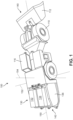
- FIG. 1 is a schematic view of an electrically powered mining vehicle 100.
- vehicle 100 may be a load haul dump (LHD) mining vehicle.
- LHD load haul dump
- the provisions described below could be incorporated into various other kind of electric vehicles.
- Vehicle 100 may include standard provisions for a mining vehicle, such as wheels 110 and scoop 112. Vehicle 100 may also include provisions for powering wheels 110 and scoop 112. Vehicle 100 is also provided with various standard vehicular mechanisms and capacities, such as passenger cab 116 for receiving one or more operators.
- a mining vehicle such as wheels 110 and scoop 112.
- Vehicle 100 may also include provisions for powering wheels 110 and scoop 112.
- Vehicle 100 is also provided with various standard vehicular mechanisms and capacities, such as passenger cab 116 for receiving one or more operators.
- vehicle 100 may be identified with three different axes. These include a lengthwise axis 150 extending through a lengthwise dimension of vehicle 100, a widthwise axis 152 extending through a widthwise dimension of vehicle 100, and a vertical axis 154 extending through a dimension associated with the height of vehicle 100.
- the widthwise axis 152 may extend between opposing side surfaces of vehicle 100, while vertical axis 154 extends between an opposing bottom surface and top surface of vehicle 100.
- Examples can incorporate a replaceable power source that powers one or more electric motors of vehicle 100.
- the term “replaceable power source” refers to any kind of power source that can be interchanged.
- a replaceable power source comprises a battery pack assembly.
- a battery pack assembly comprises two or more battery packs.
- the term “battery pack” generally refers to multiple battery modules in a heavy-duty pack housing. Each module is comprised of multiple battery cells. In this way, a battery pack also refers to a collection of individual battery cells. The battery cells, and therefore modules, are functionally interconnected together.
- a battery pack assembly may also include a casing or housing (such as a cage) or similar container for holding the separate battery packs together.
- a replaceable power source may comprise a casing or housing for retaining and supporting a powering system, such as a battery, engine or other power source.
- a battery pack could incorporate any suitable kind of battery cell.
- battery cells include capacitors, ultra-capacitors, and electrochemical cells.
- electrochemical cells include primary (e.g., single use) and secondary (e.g., rechargeable).
- secondary electrochemical cells include lead-acid, valve regulated lead-acid (VRLA), gel, absorbed glass mat (AGM), nickel-cadmium (NiCd), nickel-zinc (NiZn), nickel metal hydride (NiMH), lithium-ion (Li-ion), and the like.
- a battery cell may have various voltage levels. In particular, in some cases two different battery cells in a battery pack could have different voltage levels. Similarly, the battery cell may have various energy capacity levels. In particular, in some cases, two different battery cells in a battery pack could have different capacity levels.
- vehicle 100 is configured with a replaceable power source 130.
- Scoop 112 may be disposed at a first end 140 of vehicle 100 while replaceable power source 130 may be disposed at a second end 142.
- replaceable power source 130 could be attached to a different portion of vehicle 100.
- replaceable power source 130 includes two battery packs. These include a first battery pack 132 and a second battery pack 134. First battery pack 132 and second battery pack 134 may be disposed in a side-by-side arrangement. Moreover, first battery pack 132 and second battery pack 134 are retained within a battery cage 136.
- Replaceable power source 130 may be removably attached to vehicle 100.
- the term “removably attached” refers to two components that are joined together but that can be separated without destroying one or the other component. That is, the components can be non-destructively detached from one another.
- Exemplary modalities of "removable attachment” include connections made using removeable fasteners, latches, locks, hooks, magnetic connections as well as other kinds of connections.
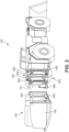
- FIG. 2 is a schematic view of vehicle 100 with replaceable power source 130 removed.
- vehicle 100 includes a mounting and dismounting system 200, also referred to simply as system 200.
- Mounting and dismounting system 200 is attached to vehicle chassis 101 (or frame) of vehicle 100. In other words, system 200 is integrated into vehicle 100.
- replaceable power source 130 includes an upper shaft 250 and a lower shaft 252. As shown in FIGS. 2-3 , each of these shafts may comprise a bar or tube that extends horizontally across one side of battery cage 136. System 200 may include features to engage these shafts and use them to lift and retain replaceable power source 130 in place against vehicle 100.
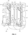
- FIG. 3 depicts an enlarged view of mounting and dismounting system 200.
- system 200 comprises a lift rack assembly 220 and a plurality of retaining members 222.
- the pieces of lift rack assembly 220 are depicted with shading in FIGS. 2-3 , to distinguish the lift rack assembly from the plurality of retaining members.
- Lift rack assembly 220 includes a pair of rack members. Specifically, a first rack member 232 and a second rack member 234. Each rack member is further comprised of two lifting portions.
- First rack member 232 includes a first upper lifting portion 240 and a first lower lifting portion 242.
- Second rack member also includes a second upper lifting portion 244 and a second lower lifting portion 246.
- the rack members are arranged to provide four points of contact with the replaceable power source.
- the rack members may be spaced in a horizontal direction (for example, along the widthwise axis 152 of vehicle 100 shown in FIG. 1 ).
- the lifting portions on each rack member may be set at different vertical heights (for example, with respect to the vertical axis 154 of vehicle 100 shown in FIG. 1 ).
- first upper lifting portion 240 and second upper lifting portion 244 are configured to engage and lift upper shaft 250 of replaceable power source 130.
- first lower lifting portion 242 and second lower lifting portion 246 are configured to engage and lift lower shaft 252 of replaceable power source 130.
- Each lifting portion is shaped and designed to hold part of a shaft as the rack members are raised and lowered. To this end, each lifting portion may be shaped like a hook.
- first upper lifting portion 240 has a curved geometry with a concave engaging surface 302. As upper lifting portion 240 engages a shaft (e.g., a bar), the shaft will slide down into the U-shaped opening formed by concave engaging surface 302. This prevents the shaft from disengaging with, or falling off of, lift rack assembly 220.
- Each of the remaining lifting portions may be seen to have a similar hook-like shape that helps cradle the shafts as they are engaged and lifted. Additionally, this concave shape helps guide the shafts (and the replaceable power source) towards the vehicle chassis 101 as the concave surfaces are sloped down towards the vehicle.
- the rack members of lift rack assembly 220 may be actuated by one or more hydraulic cylinders that act to raise and lower the rack members.
- the hydraulic cylinders are hidden by the frame and/or chassis of vehicle 100.
- the schematic side views of FIGS. 4-7 depict a hydraulic cylinder 440 that can be used to raise and lower first rack member 232.
- each rack member is driven by a separate hydraulic cylinder.
- the motions of the hydraulic cylinders may be coordinated so that first rack member 232 and second rack member 234 are raised and lowered together.
- the first rack member 232 and second rack member 234 could be connected by another component (not shown), allowing both rack members to be driven by a single hydraulic cylinder.
- a plurality of retaining members 222 may be used to hold the replaceable power source in place once it has been mounted to vehicle 100. As seen in FIG. 3 , retaining members 222 may be attached (directly or indirectly) to chassis 101. In the exemplary embodiment, plurality of retaining members 222 comprises eight retaining members. These include a first upper retaining member 271, a second upper retaining member 272, a third upper retaining member 273, a fourth upper retaining member 274, a first lower retaining member 275, a second lower retaining member 276, a third lower retaining member 277 and a fourth lower retaining member 278.
- first upper retaining member 271, second upper retaining member 272, third upper retaining member 273, and fourth upper retaining member 274 have a common vertical position that is close to the highest vertical position of first upper lifting portion 240 and second upper lifting portion 244.
- first lower retaining member 275, second lower retaining member 276, third lower retaining member 277 and fourth lower retaining member 278 have a common vertical position that is close to the highest vertical position of first lower lifting portion 242 and second lower lifting portion 246.
- Retaining members 222 may have a geometry that helps secure the shafts of a replaceable power source in place.
- each retaining member may have a hook-like shape.
- first upper retaining member 271 has a curved geometry with a concave engaging surface 304.
- concave engaging surface 304 is oriented downwardly. This inverted orientation, compared to the upward orientation of the lifting portions (for example, first upper lifting portion 240), ensures that the shafts slide up into the U-shaped opening formed by concave engaging surface 302.
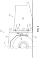
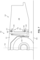
- FIG. 7 depicts replaceable power source 130 in a fully mounted position on vehicle 100.
- upper shaft 250 is prevented from moving substantially in any radial (or non-axial) direction by first upper retaining member 271 and first upper lifting portion 240.
- lower shaft 252 is prevented from moving substantially in any radial direction by first lower retaining member 275 and first lower lifting portion 242.
- Each of the remaining retaining members may be seen to have a similar inverted hook-like geometry that helps secure the shafts in place when the replaceable power source has been raised to a highest position.
- the embodiments use a total of eight retaining members, including four retaining members associated with an upper shaft and four retaining members associated with a lower shaft, other embodiments could use a different number of retaining members. Some embodiments, for example, could use only two upper retaining members and two lower retaining members.
- system 200 can include a locking system 290 to secure the lift rack in place and prevent the replaceable power source from being unintentionally lowered while mounted.
- Locking system 290 includes first hydraulic cylinder 291 and second hydraulic cylinder 292, as well as a first locking bracket 293 and a second locking bracket 294. Each hydraulic cylinder can be actuated to extend a locking pin. The locking pin may be inserted through holes in the retaining brackets as well as a hole at the top of each rack member, as described in further detail below.
- System 200 can include one or more horizontal alignment features.
- a vehicle can include one or more receiving members that are configured to engage portions of a battery cage during the mounting process.
- system 200 may include a first horizontal receiving member 280 and a second horizontal receiving member 282.
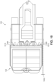
- a top down view of these receiving members is provided in FIG. 10 .
- Each horizontal receiving member comprises a tapering notch that may be engaged by a vertically oriented element (for example, a bar or tube) on battery cage 136.
- FIGS. 4-7 are schematic views showing how a mounting and dismounting system can be used to mount a replaceable power source on a vehicle. Specifically, FIGS. 4-7 depict how first rack member 232 (or simply, rack member 232) engages, lifts, and mounts replaceable power source 130 onto vehicle chassis 101 of vehicle 100. Second rack member 234 is not visible in the side views of FIGS. 4-7 , however it may be appreciated that second rack member 234 operates in an identical manner to first rack member 232. As indicated schematically in FIGS. 4-7 , the raising and lowering of first rack member 232 can be accomplished using a hydraulic cylinder 440.
- vehicle 100 may approach replaceable power source 130 in order to mount replaceable power source 130.
- Replaceable power source 130 may be disposed on a ground surface 430.
- first rack member 232 and second rack member 234 (not shown) are disposed at a lowest position 400. With the rack members at their lowest position, the lifting portions of each rack member are able to pass underneath the shafts of battery cage 136.
- first upper lifting portion 240 of first rack member 232 may be disposed below upper shaft 250.
- first lower lifting portion 242 of first rack member 232 may be disposed below lower shaft 252.
- the rack members may be raised, as depicted schematically in FIG. 6 .
- hydraulic cylinder 440 extends to raise first rack member 232.
- first upper lifting portion 240 and first lower lifting portion 242 engage upper shaft 250 and lower shaft 252, respectively.
- first upper lifting portion 240 and first lower lifting portion 242 act to lift replaceable power source 130 from ground 430.
- the lifting portions of second rack member 234 may simultaneously engage and lift the upper and lower shafts as well, so that there are four points of contact between the lift rack assembly 220 (see FIG. 3 ) and replaceable power source 130.
- First rack member 232 continues to be raised up by hydraulic cylinder 440 until first rack member 232 (and second rack member 234) reaches its highest position 702, as shown in FIG. 7 . Moreover, as first rack member 232 reaches this highest position, the shafts are raised into the concave openings of the retaining members. For example, upper shaft 250 is disposed through the concave opening of first upper retaining member 271. Also, lower shaft 252 is disposed through the concave opening of first lower retaining member 275.
- the shafts are secured between the lifting portions (from below) and the retaining members (from above).
- the geometries of the lifting portions and retaining members form overlapping arcs that prevent the shafts from moving substantially in any radial direction (that is, any direction perpendicular to the axis of the tube-like shafts).
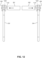
- FIGS. 11-12 a schematic front view of elements of the locking system and portions of each rack member are shown in FIGS. 11-12 .
- first rack member 232 and second rack member 234 are not in their highest positions, the first locking pin 1102 of first hydraulic cylinder 291 and second locking pin 1104 of second hydraulic cylinder 292 are retracted, as shown in FIG. 11 .
- the rack members are raised to their highest positions, as seen in FIG. 12 , the locking pins are extended through the brackets and the rack members.
- first locking pin 1102 extends through opposing holes of first locking bracket 293 as well as a locking hole 1202 (indicated in phantom) of first rack member 232.
- second locking pin 1104 extends through opposing holes of second locking bracket 294 as well as a locking hole 1204 (indicated in phantom) of second rack member 234. With the locking pins inserted through the locking holes of each rack member, the lift rack assembly is prevented from lowering.
- a similar process to the one shown in FIGS. 4-7 can be used to dismount a replaceable power source.
- the locking system can be disengaged (i.e., locking pins retracted).
- the lift rack assembly can be lowered, which decouples the shafts from the retaining members.
- the replaceable power source contacts the ground and the lifting portions are able to decouple from the shafts as they move lower.
- the vehicle can move away from the replaceable power source with the lifting portions low enough so that they do not engage the shafts.
- each rack member moves substantially along a linear direction.
- the linear direction is a vertical direction that extends in parallel with vertical axis 154 of vehicle 100.
- the mounting and dismounting system of the embodiments helps reduce the tendency of the replaceable power source to swing or tilt during lifting.
- the retaining members can be fixed in their positions and not moved into place after the shafts have been raised to a highest position. This allows the retaining members to be integrated into the chassis or other supporting structures of the vehicle without using fasteners that could fail under heavy loads.
- the ground surface may not be level. This means that as a vehicle attempts to mount or dismount a battery assembly, the patch of ground where the battery is raised from (or lowered to) may be slightly higher or lower relative to the patch of ground where the vehicle's wheels are located.
- Some embodiments of a vehicle can include provisions to ensure batteries can be mounted or dismounted on unlevel ground.
- the mounting and dismounting system described above and shown in FIGS. 1-7 enables a replaceable power source to be mounted even when the replaceable power source is not situated on a perfectly flat surface at the same level as the wheels of the vehicle.
- the lift rack assembly 220 in its lowest position, can engage a replaceable power source 802 that is disposed a distance 810 below ground level 800. In some embodiments, distance 810 may have an approximate value of 3.5 inches.
- the lift rack assembly 220 in its highest position, can engage a replaceable power source 804 that is disposed a distance 812 above ground level 800. In some embodiments, distance 812 may have an approximate value of 8.5 inches. This tolerance in the vertical displacement of a replaceable power source allows vehicle 100 to mount replaceable power sources on the uneven surfaces that often occur in underground mining tunnels.
- the mounting and dismounting system also enables a replaceable power source to be mounted even when the replaceable power source is not level with the ground or another horizontal surface.
- the lifting portions can engage the shafts of a replaceable power source 902 that is angled downwards from a level surface 920 by an angular displacement 930.
- upper shaft 250 is engaged by upper lifting portion 240 while lower shaft 252 is engaged by lower lifting portion 242.
- angular displacement 930 can have an approximate value of 6 degrees. Also, as seen in FIG.
- the lifting portions can engage the shafts of a replaceable power source 902 that is angled upwards from a level surface 922 by an angular displacement 932.
- angular displacement 932 can have an approximate value of 6 degrees. This tolerance in the angular orientation of a replaceable power source allows vehicle 100 to mount replaceable power sources on sloped ground surfaces that may occur in mining tunnels.
- vehicle 100 may include provisions to facilitate horizontal alignment of a replaceable power source.
- FIG. 10 depicts a top-down schematic view of a portion of vehicle 100, including first horizontal receiving member 280 and second horizontal receiving member 282. These receiving members facilitate horizontal alignment by catching vertically disposed elements (such as bars or struts) on a replaceable power source and guiding these elements towards a central region as the vehicle makes contact with the replaceable power source.
- replaceable power source 130 can be displaced by a distance 1002 in the horizontal direction and still have a first vertical shaft 1010 engage first horizontal receiving member 280 and a second vertical shaft 1012 engage second horizontal receiving member 282.
- distance 1002 could have a value of approximately 2.5 inches. This arrangement allows for some tolerance in the horizontal alignment between vehicle 100 and replaceable power source 130 as a vehicle is approaching the replaceable power source 130.
- the interchangeable energy device may be a battery, a different type of battery, a generator, a fuel engine, or an adaptor for any existing energy infrastructure. It will also be understood that the system may be employed with any combination of devices, such as batteries, adapters and the like. It will also be understood that the energy source is compatible with and in communication with the drive system and drive controller. The energy source, whether battery or trolley adapter, or another type of source would be compatible with the drive system and controller.
- electric vehicle refers to a vehicle that uses electrical power for propulsion purposes, at least in one mode of operation.
- electric vehicles include all-electric vehicles (e.g., a vehicle with a traction motor and only an onboard electrical energy storage device or mechanism for receiving electric energy from an off-board source, such as an overhead catenary or powered rail), hybrid-electric vehicles (e.g., a vehicle with a traction motor, an energy storage device, hydraulic propulsion, and a fuel engine, fuel cell, or the like for charging the energy storage device and/or directly generating power for running the traction motor), dual-mode vehicles (e.g., a vehicle with an engine-only mode of operation and an electricity-only mode of operation, or a vehicle with a first mode of operation where traction electricity is provided by an engine and a second mode of operation where traction electricity is provided by another source), diesel-electric and other engine-electric vehicles (e.g., a vehicle with an engine that generates electrical power for running a traction motor), and
- all-electric vehicles e.
- the vehicle interface equipment of the wayside stations may comprise: "plug in” modules, e.g., the vehicle plugs into a receptacle of the wayside station, for receiving electrical power from the station; a continuous power interface by which a vehicle can receive off-board power while moving, such as the aforementioned catenary line or third rail; or the like.
Landscapes
- Engineering & Computer Science (AREA)
- Mechanical Engineering (AREA)
- Transportation (AREA)
- Power Engineering (AREA)
- Sustainable Development (AREA)
- Life Sciences & Earth Sciences (AREA)
- Sustainable Energy (AREA)
- Chemical & Material Sciences (AREA)
- Combustion & Propulsion (AREA)
- Arrangement Or Mounting Of Propulsion Units For Vehicles (AREA)
- Electric Propulsion And Braking For Vehicles (AREA)
- Battery Mounting, Suspending (AREA)
- Vehicle Cleaning, Maintenance, Repair, Refitting, And Outriggers (AREA)
- Charge And Discharge Circuits For Batteries Or The Like (AREA)
Applications Claiming Priority (2)
| Application Number | Priority Date | Filing Date | Title |
|---|---|---|---|
| US16/434,396 US11254224B2 (en) | 2019-06-07 | 2019-06-07 | Battery load mechanism for electric LHD mining machine |
| PCT/US2020/036096 WO2020247611A1 (en) | 2019-06-07 | 2020-06-04 | Battery load mechanism for electric lhd mining machine |
Publications (4)
| Publication Number | Publication Date |
|---|---|
| EP3980286A1 EP3980286A1 (en) | 2022-04-13 |
| EP3980286A4 EP3980286A4 (en) | 2023-07-05 |
| EP3980286B1 true EP3980286B1 (en) | 2025-02-26 |
| EP3980286C0 EP3980286C0 (en) | 2025-02-26 |
Family
ID=73651175
Family Applications (1)
| Application Number | Title | Priority Date | Filing Date |
|---|---|---|---|
| EP20818548.8A Active EP3980286B1 (en) | 2019-06-07 | 2020-06-04 | Battery load mechanism for electric lhd mining machine |
Country Status (13)
| Country | Link |
|---|---|
| US (1) | US11254224B2 (pl) |
| EP (1) | EP3980286B1 (pl) |
| JP (1) | JP7668232B2 (pl) |
| CN (1) | CN113874247B (pl) |
| AU (1) | AU2020287625B2 (pl) |
| CA (1) | CA3135572C (pl) |
| CL (1) | CL2021003220A1 (pl) |
| EA (1) | EA202192851A1 (pl) |
| MX (1) | MX2021015067A (pl) |
| PE (1) | PE20212221A1 (pl) |
| PL (1) | PL3980286T3 (pl) |
| WO (1) | WO2020247611A1 (pl) |
| ZA (1) | ZA202107942B (pl) |
Families Citing this family (11)
| Publication number | Priority date | Publication date | Assignee | Title |
|---|---|---|---|---|
| US20220077441A1 (en) * | 2020-09-09 | 2022-03-10 | Caterpillar Inc. | Battery system for industrial machine |
| US11396237B2 (en) * | 2020-09-28 | 2022-07-26 | Artisan Vehicle Systems, Inc. | Battery assembly stabilization mechanism |
| CN114290946B (zh) * | 2021-12-28 | 2024-02-27 | 浙江科力车辆控制系统有限公司 | 换电系统及方法 |
| CN115332704A (zh) * | 2022-06-29 | 2022-11-11 | 青岛中鸿重型机械有限公司 | 一种用于可更换电池安装和拆卸系统 |
| CN115288217A (zh) * | 2022-07-11 | 2022-11-04 | 青岛中鸿重型机械有限公司 | 一种具备快换电池组功能的纯电动地下铲运机 |
| USD1088056S1 (en) * | 2022-09-20 | 2025-08-12 | Sandvik Mining And Construction Oy | Drill rig |
| CA3219701A1 (en) * | 2022-11-11 | 2024-05-11 | Joy Global Underground Mining Llc | Energy storage system for vehicle and alignment system for same |
| CN116101044B (zh) * | 2022-12-26 | 2026-03-20 | 上海凯煦传动科技有限公司 | 一种地下电动铲运机的储能电池快换工装及使用方法 |
| DE102023202726A1 (de) * | 2023-03-27 | 2024-10-17 | Scheuerle Fahrzeugfabrik Gmbh | Energieversorgungseinheit, System und Schwerlast-Modulfahrzeug |
| JP2024161757A (ja) * | 2023-05-08 | 2024-11-20 | 株式会社小松製作所 | 作業機械及びバッテリパックの交換方法 |
| EP4631755A1 (en) * | 2024-04-09 | 2025-10-15 | Volvo Truck Corporation | Hook suspended energy storage module |
Citations (1)
| Publication number | Priority date | Publication date | Assignee | Title |
|---|---|---|---|---|
| JP2001088563A (ja) * | 1999-09-28 | 2001-04-03 | Fuji Heavy Ind Ltd | 電気自動車のバッテリボックス搭載構造 |
Family Cites Families (47)
| Publication number | Priority date | Publication date | Assignee | Title |
|---|---|---|---|---|
| US3799063A (en) | 1972-08-16 | 1974-03-26 | D Reed | Vehicle battery changing device |
| US3834563A (en) | 1972-10-10 | 1974-09-10 | Ato Inc | Battery carrier |
| JPS5620250Y2 (pl) * | 1976-10-08 | 1981-05-14 | ||
| SE422932B (sv) * | 1980-06-02 | 1982-04-05 | Atlas Copco Ab | Batteridriven lastmaskin med ett lyftorgan for batteripaket samt en fristaende stodpall for att uppbera batteripaketet |
| US4636133A (en) | 1985-01-23 | 1987-01-13 | Crothers Limited | Heavy load lifting apparatus |
| US4808058A (en) * | 1987-09-29 | 1989-02-28 | Carney Wayne D | Battery handling machine |
| US5163537A (en) * | 1991-04-29 | 1992-11-17 | Simmons-Rand Company | Battery changing system for electric battery-powered vehicles |
| US5612606A (en) | 1994-09-15 | 1997-03-18 | David C. Guimarin | Battery exchange system for electric vehicles |
| US5664932A (en) * | 1994-09-20 | 1997-09-09 | Long-Airdox Company | Pivoted lifting device |
| US5598083A (en) * | 1995-05-19 | 1997-01-28 | Stamler Corporation | Battery changing system for electrically powered vehicle |
| US5820331A (en) * | 1997-02-10 | 1998-10-13 | Fairchild International Inc. | Battery changing system |
| US5879125A (en) * | 1997-02-10 | 1999-03-09 | Fairchild International Inc. | Battery changing system |
| GB2331054B (en) * | 1997-11-06 | 2001-08-08 | Lansing Linde Ltd | Industrial truck with a battery block |
| CN1339001A (zh) * | 1999-03-25 | 2002-03-06 | 南洋理工大学 | 电池系统和装置 |
| WO2002022388A1 (en) | 2000-09-13 | 2002-03-21 | Phillips Machine Service, Inc. | Battery powered shuttle car |
| GB2411389B (en) * | 2003-11-10 | 2006-07-05 | Lansing Linde Ltd | Battery replacement system for an industrial truck |
| US7602143B2 (en) | 2005-11-04 | 2009-10-13 | Peter David Capizzo | System for replenishing energy sources onboard different types of automotive vehicles |
| US7690880B2 (en) | 2006-04-25 | 2010-04-06 | Clark Equipment Company | Locking device for hydraulic attachment interface |
| DE102006031461A1 (de) * | 2006-07-07 | 2008-01-10 | Jungheinrich Aktiengesellschaft | Batteriewechselsystem für ein batteriebetriebenes Flurförderzeug |
| US7993155B2 (en) | 2008-09-19 | 2011-08-09 | Better Place GmbH | System for electrically connecting batteries to electric vehicles |
| US8006793B2 (en) | 2008-09-19 | 2011-08-30 | Better Place GmbH | Electric vehicle battery system |
| US8146694B2 (en) * | 2009-01-20 | 2012-04-03 | Vahid Hamidi | Swappable modulated battery packs system for electrically driven vehicle |
| DE102009025052A1 (de) * | 2009-06-10 | 2011-04-28 | Gottwald Port Technology Gmbh | System zum Wechseln einer Batterie eines flurgebundenen Tranportfahrzeuges, insbesondere eines fahrerlosen Schwerlast-Transportfahrzeuges für ISO-Container |
| FR2952334B1 (fr) | 2009-11-12 | 2011-10-28 | Renault Sa | Dispositif pour le remplacement d'une batterie d'alimentation d'un moteur d'entrainement d'un vehicule automobile. |
| JP4915447B2 (ja) * | 2009-12-25 | 2012-04-11 | トヨタ自動車株式会社 | バッテリの車両搭載構造 |
| US8292015B2 (en) | 2010-07-21 | 2012-10-23 | Caterpillar Global Mining America Llc | Battery-powered mining vehicle |
| FR2988040B1 (fr) | 2012-03-15 | 2014-04-25 | Renault Sa | Systeme de verrouillage/deverrouillage d'un objet sur une structure a elements d'appui et d'alignement integres aux outils |
| US8973254B2 (en) | 2013-03-07 | 2015-03-10 | Jasper Ev Tech, Llc | System and method for rapid battery exchange in electric vehicles |
| US9969283B2 (en) * | 2013-09-10 | 2018-05-15 | General Electric Company | Battery changing system and method |
| US9960396B2 (en) | 2013-09-24 | 2018-05-01 | Artisan Vehicle Systems Inc. | Module backbone system |
| US10063069B1 (en) | 2014-05-23 | 2018-08-28 | Artisan Vehicle Systems Inc. | Module maintenance system |
| US9358895B2 (en) * | 2013-10-28 | 2016-06-07 | Meir Avganim | Quick loading and unloading battery system for vehicles |
| CN106627082B (zh) * | 2014-09-18 | 2018-11-16 | 浙江吉利控股集团有限公司 | 一种电动车辆 |
| EP3307585B1 (en) | 2015-06-10 | 2019-12-18 | Battswap, Inc. | Battery exchange system |
| CN105383839A (zh) * | 2015-12-16 | 2016-03-09 | 宁夏合力万兴汽车制造有限公司 | 挂桶垃圾车提升机 |
| US9937818B2 (en) * | 2016-02-09 | 2018-04-10 | Nio Usa, Inc. | Vehicle having a rigid frame structure for receiving a replaceable battery pack |
| US9994117B2 (en) | 2016-04-20 | 2018-06-12 | Artisan Vehicle Systems Inc. | System and method for providing power to a mining operation |
| US11035095B2 (en) | 2016-09-23 | 2021-06-15 | Artisan Vehicle Systems, Inc. | Electrically powered mining vehicle |
| US11981226B2 (en) * | 2017-07-19 | 2024-05-14 | Ford Global Technologies, Llc | Swappable battery system |
| CN109693527B (zh) * | 2017-10-20 | 2022-01-07 | 河南奔马股份有限公司 | 一种自动更换电池箱的车辆 |
| US10926660B2 (en) | 2018-02-28 | 2021-02-23 | Artisan Vehicle Systems, Inc. | Mounting and dismounting system for a battery assembly |
| US10668830B2 (en) | 2018-02-28 | 2020-06-02 | Artisan Vehicle Systems Inc. | Method and system for mounting and dismounting batteries in a vehicle |
| US10906383B2 (en) | 2018-02-28 | 2021-02-02 | Artisan Vehicle Systems, Inc. | Alignment and locking mechanism for removeable battery assembly |
| US10836242B2 (en) | 2018-02-28 | 2020-11-17 | Artisan Vehicle Systems, Inc. | Electric haul truck |
| CN208515563U (zh) * | 2018-07-20 | 2019-02-19 | 四川江淮汽车有限公司 | 一种用于电动轻卡动力电池的快换机构 |
| US11453309B2 (en) | 2018-09-06 | 2022-09-27 | Artisan Vehicle Systems, Inc. | Electric power distribution system and method for electric mining machine |
| US20200157769A1 (en) | 2018-09-06 | 2020-05-21 | Artisan Vehicle Systems, Inc. | Electric Load-Haul-Dump Mining Machine |
-
2019
- 2019-06-07 US US16/434,396 patent/US11254224B2/en active Active
-
2020
- 2020-06-04 PL PL20818548.8T patent/PL3980286T3/pl unknown
- 2020-06-04 EP EP20818548.8A patent/EP3980286B1/en active Active
- 2020-06-04 EA EA202192851A patent/EA202192851A1/ru unknown
- 2020-06-04 CN CN202080038335.6A patent/CN113874247B/zh active Active
- 2020-06-04 CA CA3135572A patent/CA3135572C/en active Active
- 2020-06-04 JP JP2021572420A patent/JP7668232B2/ja active Active
- 2020-06-04 AU AU2020287625A patent/AU2020287625B2/en active Active
- 2020-06-04 PE PE2021001754A patent/PE20212221A1/es unknown
- 2020-06-04 MX MX2021015067A patent/MX2021015067A/es unknown
- 2020-06-04 WO PCT/US2020/036096 patent/WO2020247611A1/en not_active Ceased
-
2021
- 2021-10-18 ZA ZA2021/07942A patent/ZA202107942B/en unknown
- 2021-12-03 CL CL2021003220A patent/CL2021003220A1/es unknown
Patent Citations (1)
| Publication number | Priority date | Publication date | Assignee | Title |
|---|---|---|---|---|
| JP2001088563A (ja) * | 1999-09-28 | 2001-04-03 | Fuji Heavy Ind Ltd | 電気自動車のバッテリボックス搭載構造 |
Also Published As
| Publication number | Publication date |
|---|---|
| US20200384869A1 (en) | 2020-12-10 |
| JP7668232B2 (ja) | 2025-04-24 |
| MX2021015067A (es) | 2022-01-18 |
| CA3135572C (en) | 2025-05-27 |
| ZA202107942B (en) | 2024-04-24 |
| EP3980286A1 (en) | 2022-04-13 |
| EA202192851A1 (ru) | 2022-03-16 |
| PE20212221A1 (es) | 2021-11-23 |
| CN113874247A (zh) | 2021-12-31 |
| PL3980286T3 (pl) | 2025-07-28 |
| JP2022535288A (ja) | 2022-08-05 |
| EP3980286A4 (en) | 2023-07-05 |
| CA3135572A1 (en) | 2020-12-10 |
| CL2021003220A1 (es) | 2022-08-19 |
| AU2020287625B2 (en) | 2025-07-31 |
| AU2020287625A1 (en) | 2021-11-18 |
| WO2020247611A1 (en) | 2020-12-10 |
| CN113874247B (zh) | 2024-07-05 |
| US11254224B2 (en) | 2022-02-22 |
| EP3980286C0 (en) | 2025-02-26 |
Similar Documents
| Publication | Publication Date | Title |
|---|---|---|
| EP3980286B1 (en) | Battery load mechanism for electric lhd mining machine | |
| US11541739B2 (en) | Electric haul truck | |
| EP3758982B1 (en) | Mounting and dismounting system for a battery assembly | |
| US12077062B2 (en) | Method and system for automatically connecting and disconnecting batteries for electric vehicles | |
| US20120181981A1 (en) | Energy supply unit, land vehicle, replacement station and method for replacement of an energy supply unit contained in a land vehicle | |
| AU2019227644A1 (en) | Method and system for mounting and dismounting batteries in a vehicle | |
| US12139025B2 (en) | Battery assembly stabilization mechanism | |
| EA044773B1 (ru) | Механизм загрузки аккумулятора для электрической погрузочно-доставочной шахтной машины | |
| EP4299366A1 (en) | Method and apparatus for mounting and dismounting battery of a mobile mining machine and a mobile mining machine | |
| RU2788544C2 (ru) | Способ и устройство установки и снятия аккумуляторов транспортного средства | |
| EA040335B1 (ru) | Система установки и снятия аккумуляторов для узла аккумуляторов | |
| EA040328B1 (ru) | Механизм выравнивания и фиксации для съемного узла аккумуляторов |
Legal Events
| Date | Code | Title | Description |
|---|---|---|---|
| STAA | Information on the status of an ep patent application or granted ep patent |
Free format text: STATUS: THE INTERNATIONAL PUBLICATION HAS BEEN MADE |
|
| PUAI | Public reference made under article 153(3) epc to a published international application that has entered the european phase |
Free format text: ORIGINAL CODE: 0009012 |
|
| STAA | Information on the status of an ep patent application or granted ep patent |
Free format text: STATUS: REQUEST FOR EXAMINATION WAS MADE |
|
| 17P | Request for examination filed |
Effective date: 20220107 |
|
| AK | Designated contracting states |
Kind code of ref document: A1 Designated state(s): AL AT BE BG CH CY CZ DE DK EE ES FI FR GB GR HR HU IE IS IT LI LT LU LV MC MK MT NL NO PL PT RO RS SE SI SK SM TR |
|
| DAV | Request for validation of the european patent (deleted) | ||
| DAX | Request for extension of the european patent (deleted) | ||
| A4 | Supplementary search report drawn up and despatched |
Effective date: 20230606 |
|
| RIC1 | Information provided on ipc code assigned before grant |
Ipc: B60L 53/80 20190101ALI20230531BHEP Ipc: B60L 50/60 20190101ALI20230531BHEP Ipc: B60S 5/06 20190101ALI20230531BHEP Ipc: B60K 1/04 20190101AFI20230531BHEP |
|
| RAP1 | Party data changed (applicant data changed or rights of an application transferred) |
Owner name: SANDVIK MINING AND CONSTRUCTION OY |
|
| GRAP | Despatch of communication of intention to grant a patent |
Free format text: ORIGINAL CODE: EPIDOSNIGR1 |
|
| STAA | Information on the status of an ep patent application or granted ep patent |
Free format text: STATUS: GRANT OF PATENT IS INTENDED |
|
| INTG | Intention to grant announced |
Effective date: 20240725 |
|
| GRAJ | Information related to disapproval of communication of intention to grant by the applicant or resumption of examination proceedings by the epo deleted |
Free format text: ORIGINAL CODE: EPIDOSDIGR1 |
|
| STAA | Information on the status of an ep patent application or granted ep patent |
Free format text: STATUS: REQUEST FOR EXAMINATION WAS MADE |
|
| GRAP | Despatch of communication of intention to grant a patent |
Free format text: ORIGINAL CODE: EPIDOSNIGR1 |
|
| STAA | Information on the status of an ep patent application or granted ep patent |
Free format text: STATUS: GRANT OF PATENT IS INTENDED |
|
| INTC | Intention to grant announced (deleted) | ||
| INTG | Intention to grant announced |
Effective date: 20241107 |
|
| GRAS | Grant fee paid |
Free format text: ORIGINAL CODE: EPIDOSNIGR3 |
|
| GRAA | (expected) grant |
Free format text: ORIGINAL CODE: 0009210 |
|
| STAA | Information on the status of an ep patent application or granted ep patent |
Free format text: STATUS: THE PATENT HAS BEEN GRANTED |
|
| AK | Designated contracting states |
Kind code of ref document: B1 Designated state(s): AL AT BE BG CH CY CZ DE DK EE ES FI FR GB GR HR HU IE IS IT LI LT LU LV MC MK MT NL NO PL PT RO RS SE SI SK SM TR |
|
| REG | Reference to a national code |
Ref country code: GB Ref legal event code: FG4D |
|
| REG | Reference to a national code |
Ref country code: CH Ref legal event code: EP |
|
| REG | Reference to a national code |
Ref country code: DE Ref legal event code: R096 Ref document number: 602020046884 Country of ref document: DE |
|
| REG | Reference to a national code |
Ref country code: IE Ref legal event code: FG4D |
|
| U01 | Request for unitary effect filed |
Effective date: 20250303 |
|
| U07 | Unitary effect registered |
Designated state(s): AT BE BG DE DK EE FI FR IT LT LU LV MT NL PT RO SE SI Effective date: 20250311 |
|
| U20 | Renewal fee for the european patent with unitary effect paid |
Year of fee payment: 6 Effective date: 20250509 |
|
| PG25 | Lapsed in a contracting state [announced via postgrant information from national office to epo] |
Ref country code: RS Free format text: LAPSE BECAUSE OF FAILURE TO SUBMIT A TRANSLATION OF THE DESCRIPTION OR TO PAY THE FEE WITHIN THE PRESCRIBED TIME-LIMIT Effective date: 20250526 |
|
| PG25 | Lapsed in a contracting state [announced via postgrant information from national office to epo] |
Ref country code: ES Free format text: LAPSE BECAUSE OF FAILURE TO SUBMIT A TRANSLATION OF THE DESCRIPTION OR TO PAY THE FEE WITHIN THE PRESCRIBED TIME-LIMIT Effective date: 20250226 |
|
| PG25 | Lapsed in a contracting state [announced via postgrant information from national office to epo] |
Ref country code: IS Free format text: LAPSE BECAUSE OF FAILURE TO SUBMIT A TRANSLATION OF THE DESCRIPTION OR TO PAY THE FEE WITHIN THE PRESCRIBED TIME-LIMIT Effective date: 20250626 Ref country code: NO Free format text: LAPSE BECAUSE OF FAILURE TO SUBMIT A TRANSLATION OF THE DESCRIPTION OR TO PAY THE FEE WITHIN THE PRESCRIBED TIME-LIMIT Effective date: 20250526 |
|
| PG25 | Lapsed in a contracting state [announced via postgrant information from national office to epo] |
Ref country code: HR Free format text: LAPSE BECAUSE OF FAILURE TO SUBMIT A TRANSLATION OF THE DESCRIPTION OR TO PAY THE FEE WITHIN THE PRESCRIBED TIME-LIMIT Effective date: 20250226 |
|
| PG25 | Lapsed in a contracting state [announced via postgrant information from national office to epo] |
Ref country code: GR Free format text: LAPSE BECAUSE OF FAILURE TO SUBMIT A TRANSLATION OF THE DESCRIPTION OR TO PAY THE FEE WITHIN THE PRESCRIBED TIME-LIMIT Effective date: 20250527 |
|
| PGFP | Annual fee paid to national office [announced via postgrant information from national office to epo] |
Ref country code: CZ Payment date: 20250529 Year of fee payment: 6 |
|
| PG25 | Lapsed in a contracting state [announced via postgrant information from national office to epo] |
Ref country code: SM Free format text: LAPSE BECAUSE OF FAILURE TO SUBMIT A TRANSLATION OF THE DESCRIPTION OR TO PAY THE FEE WITHIN THE PRESCRIBED TIME-LIMIT Effective date: 20250226 |
|
| PGFP | Annual fee paid to national office [announced via postgrant information from national office to epo] |
Ref country code: PL Payment date: 20250429 Year of fee payment: 6 |
|
| PG25 | Lapsed in a contracting state [announced via postgrant information from national office to epo] |
Ref country code: SK Free format text: LAPSE BECAUSE OF FAILURE TO SUBMIT A TRANSLATION OF THE DESCRIPTION OR TO PAY THE FEE WITHIN THE PRESCRIBED TIME-LIMIT Effective date: 20250226 |
|
| PLBE | No opposition filed within time limit |
Free format text: ORIGINAL CODE: 0009261 |
|
| STAA | Information on the status of an ep patent application or granted ep patent |
Free format text: STATUS: NO OPPOSITION FILED WITHIN TIME LIMIT |
|
| REG | Reference to a national code |
Ref country code: CH Ref legal event code: L10 Free format text: ST27 STATUS EVENT CODE: U-0-0-L10-L00 (AS PROVIDED BY THE NATIONAL OFFICE) Effective date: 20260107 |
|
| REG | Reference to a national code |
Ref country code: CH Ref legal event code: H13 Free format text: ST27 STATUS EVENT CODE: U-0-0-H10-H13 (AS PROVIDED BY THE NATIONAL OFFICE) Effective date: 20260127 |
|
| PG25 | Lapsed in a contracting state [announced via postgrant information from national office to epo] |
Ref country code: MC Free format text: LAPSE BECAUSE OF FAILURE TO SUBMIT A TRANSLATION OF THE DESCRIPTION OR TO PAY THE FEE WITHIN THE PRESCRIBED TIME-LIMIT Effective date: 20250226 |
|
| 26N | No opposition filed |
Effective date: 20251127 |
|
| GBPC | Gb: european patent ceased through non-payment of renewal fee |
Effective date: 20250604 |