EP3980253B1 - Verfahren und systeme zur herstellung einer verknüpfung zwischen einer dreidimensionalen elektronischen designdatei und einem zweidimensionalen designdokument - Google Patents
Verfahren und systeme zur herstellung einer verknüpfung zwischen einer dreidimensionalen elektronischen designdatei und einem zweidimensionalen designdokument Download PDFInfo
- Publication number
- EP3980253B1 EP3980253B1 EP20819323.5A EP20819323A EP3980253B1 EP 3980253 B1 EP3980253 B1 EP 3980253B1 EP 20819323 A EP20819323 A EP 20819323A EP 3980253 B1 EP3980253 B1 EP 3980253B1
- Authority
- EP
- European Patent Office
- Prior art keywords
- design
- coded
- image
- elements
- file
- Prior art date
- Legal status (The legal status is an assumption and is not a legal conclusion. Google has not performed a legal analysis and makes no representation as to the accuracy of the status listed.)
- Active
Links
Images





Classifications
-
- G—PHYSICS
- G06—COMPUTING OR CALCULATING; COUNTING
- G06F—ELECTRIC DIGITAL DATA PROCESSING
- G06F30/00—Computer-aided design [CAD]
- G06F30/10—Geometric CAD
- G06F30/13—Architectural design, e.g. computer-aided architectural design [CAAD] related to design of buildings, bridges, landscapes, production plants or roads
-
- G—PHYSICS
- G06—COMPUTING OR CALCULATING; COUNTING
- G06F—ELECTRIC DIGITAL DATA PROCESSING
- G06F30/00—Computer-aided design [CAD]
- G06F30/10—Geometric CAD
- G06F30/12—Geometric CAD characterised by design entry means specially adapted for CAD, e.g. graphical user interfaces [GUI] specially adapted for CAD
-
- G—PHYSICS
- G06—COMPUTING OR CALCULATING; COUNTING
- G06T—IMAGE DATA PROCESSING OR GENERATION, IN GENERAL
- G06T19/00—Manipulating three-dimensional [3D] models or images for computer graphics
-
- G—PHYSICS
- G06—COMPUTING OR CALCULATING; COUNTING
- G06F—ELECTRIC DIGITAL DATA PROCESSING
- G06F2111/00—Details relating to CAD techniques
- G06F2111/02—CAD in a network environment, e.g. collaborative CAD or distributed simulation
-
- G—PHYSICS
- G06—COMPUTING OR CALCULATING; COUNTING
- G06T—IMAGE DATA PROCESSING OR GENERATION, IN GENERAL
- G06T2200/00—Indexing scheme for image data processing or generation, in general
- G06T2200/24—Indexing scheme for image data processing or generation, in general involving graphical user interfaces [GUIs]
-
- G—PHYSICS
- G06—COMPUTING OR CALCULATING; COUNTING
- G06T—IMAGE DATA PROCESSING OR GENERATION, IN GENERAL
- G06T2210/00—Indexing scheme for image generation or computer graphics
- G06T2210/04—Architectural design, interior design
-
- G—PHYSICS
- G06—COMPUTING OR CALCULATING; COUNTING
- G06T—IMAGE DATA PROCESSING OR GENERATION, IN GENERAL
- G06T2219/00—Indexing scheme for manipulating 3D models or images for computer graphics
- G06T2219/004—Annotating, labelling
Definitions
- the present disclosure relates to systems and methods for object identification in a design file. More particularly, the present disclosure relates to systems and methods for establishing a linkage between a three-dimensional (3D) design file and a two-dimensional (2D) design document. The present disclosure further relates to systems and methods for identifying a design element in a 3D design model based on a user-selected point in a 2D design image.
- Building information model (BIM) files contain a rich data set comprising a three-dimensional (3D) geometry of design elements (e.g., building objects), as well as specific details of the design elements. Even though the BIM holistically represents a comprehensive data set, two-dimensional (2D) design images or drawings are extensively used both onsite and offsite in the AEC (architecture, engineering, and construction) industry.
- 3D three-dimensional
- Document CN 106354945 discloses a drawing association module to associate a 3D BIM model with 2D engineering drawings.
- a synchronization model module synchronizes the 3D BIM model through the 2D engineering drawing base point and two-dimensional engineering drawings.
- a data dynamic association module associates the 2D engineering drawings associated 3D BIM model with the engineering data and form a lightweight BIM model.
- One embodiment provides a computer-implemented method for linking a two-dimensional (2D) design image to a three-dimensional (3D) design model, comprising: receiving a 2D design document and a 3D design file, the 2D design document comprising a 2D design image and the 3D design file comprising a 3D design model including one or more design elements; converting the 3D design model to a coded 2D design image, the coded 2D design image comprising one or more coded 2D design elements corresponding to the one or more design elements; determining a unique identifier for each of the one or more design elements based on a code of a coded 2D design element of the one or more coded 2D design elements, the code corresponding to a design element of the one or more design elements; storing each unique identifier in association with the respective design element in the 3D design file; determining an alignment between the 2D design image and the coded 2D design image; receiving a user selection of a point in die 2D design image; determining a reference
- One embodiment provides a system for linking a two-dimensional (2D) design image to a three-dimensional (3D) design model.
- the system may comprise one or more processors; and a non-transitory computer readable medium storing instructions which, when executed by the one or more processors, cause the one or more processors to perform a method comprising: receiving a 2D design document and a 3D design file, the 2D design document comprising a 2D design image and the 3D design file comprising a 3D design model including one or more design elements; converting the 3D design model to a coded 2D design image, the coded 2D design image comprising one or more coded 2D design elements corresponding to the one or more design elements; determining a unique identifier for each of the one or more design elements based on a code of a coded 2D design element of the one or more coded 2D design elements, the code corresponding to a design element of the one or more design elements; storing each unique identifier in association with the respective design element in
- Non-transitory computer readable medium for linking a two-dimensional (2D) design image to a three-dimensional (3D) design model.
- the non-transitory computer readable medium may store instructions that, when executed by one or more processors, cause the one or more processors to perform a method comprising: receiving a 2D design document and a 3D design file, the 2D design document comprising a 2D design image and the 3D design file comprising a 3D design model including one or more design elements: converting the 3D design model to a coded 2D design image, the coded 2D design image comprising one or more coded 2D design elements corresponding to the one or more design elements; determining a unique identifier for each of the one or more design elements based on a code of a coded 2D design element of the one or more coded 2D design elements, the code corresponding to a design element of the one or more design elements; storing each unique identifier in association with the respective design element in the 3D design file; determining
- the following embodiments describe methods and systems for object identification in a design file and, more particularly, for establishing a linkage between a three-dimensional (3D) design file and a two-dimensional (2D) design document.
- Building information model (BIM) files contain a rich data set comprising 3D geometry of design elements (e.g., building objects) as well as specific details of the design elements.
- the details, or die properties of a design element may include dimensions for a specific shape, physical values for materials, relations to other design elements, time-related values for task scheduling, and so forth.
- the properties may represent all required data during a life cycle of the design project, from design, engineering, and construction to facility management and operations.
- the BIM holistically represents a comprehensive data set
- the most prevalent form of information source in the AEC (architecture, engineering, and construction) industry both onsite and offsite may be a two-dimensional (2D) design image or drawing, due to its ability to concisely represent design information based on project-specific discipline needs.
- Domain-specific symbols and annotations may provide additional information for workers to understand the design from specific viewpoints.
- the current disconnect between the BIM and the 2D design drawing creates a significant inefficiency when attempting to cross-reference between these two disparate information sources. For instance, during design reviews, certain issues detected in the drawings often require additional, more detailed information to better understand and/or resolve the detected issues.
- referencing from a 2D design drawing to a BIM can be accomplished via manual reference techniques.
- the disclosed embodiments may facilitate a more convenient design review process by enabling BIM data to be directly included in 2D drawing representations.
- the disclosed embodiments are directed to establishing a linkage between a 3D design file and a 2D design document, by using a color-coded 2D design image projected from a 3D design model contained in the 3D design file.
- a 3D design model of a 3D design file may be projected onto a 2D space, creating a 2D representation of the 3D design model.
- a color or other indicator may be assigned to each design element in the 2D representation, forming a coded 2D design image, such as a color-coded 2D design image.
- any indicators may be used with techniques presented herein. For example, patterns, shapes, tags, alphanumeric or other characters, tooltips, symbols, etc., may be used as indicators.
- the value representing the color of each design element in the color-coded 2D design image such as an RGB value, may be stored in the 3D design file as the unique identifier for that design element. Subsequently, when a user selects a point in a 2D design image of a 2D design document, the point will be mapped to a reference point in the color-coded 2D design image.
- the color value, or other indicator value, of the design element over which the reference point lies in the color-coded 2D design image may be used to find a matching unique identifier in the 3D design file. Once the matching unique identifier is found, detailed information stored in the 3D design file in association with the matching unique identifier (i.e., detailed information on the design element) may be retrieved and displayed with the 2D design image. While the color-coded 2D design image may be referred to as such herein, it needn't be color-coded, and various embodiments may utilize any image that is a representation of the 3D design model.
- subject matter may be embodied as methods, devices, components, or systems. Accordingly, embodiments may, for example, take the form of hardware, software, firmware or any combination thereof. The following detailed description is, therefore, not intended to be taken in a limiting sense.
- FIG. 1 shows a block diagram of an exemplary document review application, according to one aspect of the present disclosure.
- the document review application 100 may be installed on a computing device consistent with or similar to that depicted in FIG. 6 .
- the document review application 100 may comprise a document review component 155 and a model-to-document linkage component 105.
- the document review component 155 may enable a user to locate a 2D or 3D design document from a local or remote storage, open and make modifications to the design document (e.g., add, remove, or modify drawings, annotations, markups, etc.), save the modified design document in a local or remote storage, delete the design document, collaborate with other users synchronously or asynchronously to review/edit the design document, etc.
- the document review component 155 may be a PDF document reviewing/editing software component.
- the document review component 155 may be a document reviewing/editing software component also compatible with other types of files such as, e.g., BIM files, word processing documents, CAD drawings, etc.
- the documents reviewed using the document review component 155 may include, but may not be limited to, architectural drawings, engineering drawings, and construction drawings (i.e., documents frequently used in the AEC industry).
- the model-to-document linkage component 105 may establish a linkage between a 2D design document and a 3D design file, such that a user may be able to retrieve relevant information stored in the 3D design file while interacting with the 2D design document.
- the 3D design file may be a BIM file, or any data file that includes a 3D design model, the 3D design model comprising design elements (e.g., walls, column, stairways, doors, windows, etc.) and information relevant to the design elements.
- the design elements in the 3D design model may thus be 3D design elements.
- the information relevant to each design element may be stored as a design element data set.
- the 2D design document may comprise an electronic document that includes 2D images of design elements.
- the 2D design document may also comprise supplemental information, such as annotations added by a user.
- the 2D design document may be, for example, a PDF document, which may be reviewed and edited via the document review component 155.
- the information contained in the 3D design file may be more comprehensive and extensive compared to the information contained in the 2D design document. However, in some cases, the information contained in the 3D design file may not be more comprehensive or extensive compared to the information contained in the 2D design document.
- model-to-document linkage component 105 may comprise a model conversion module 110, a model-to-document alignment module 120, and a model object identification module 130.
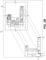
- FIGs. 2A-2C illustrate the functions performed by the model conversion module 110, model-to-document alignment module 120, and/or model object identification module 130, according to one aspect of the present disclosure. In the discussion below, references will be made to both FIG. 1 and FIGs. 2A-2C .
- While techniques discussed herein may refer to various steps being performed by different modules, such as the model conversion module 110, the model-to-document alignment module 120, and the model object identification module 130, such steps may be performed by any module or software component discussed herein, on one or multiple computers, may be performed by one or across multiple devices, and/or within a single or across multiple software applications.
- the model conversion module 110 may convert a 3D design model in the 3D design file to a color-coded 2D design image, as shown in FIG. 2A , in order to assign unique identifiers to the design elements in the 3D design model.
- the 3D design file and the 3D design model 210 contained therein may be retrieved from a local or remote storage (e.g., automatically or based on user selection), or may be received from a user via the computer's input/output (I/O) interface. While the 3D design model 210 may be converted to a color-coded 2D design image 220, the original 3D design model 210 may be retained for further usage and data gathering.
- the color-coded 2D design image 220 may be generated by projecting the 3D design model 210 onto a 2D space to create a 2D design image, which is a 2D visual representation of the 3D design model 210, and assigning a color to each design element in the 2D design image.
- a design element may be a line, a set of lines, a geometrical shape, or a polygon that represents an object within a design image, such as a wall, column, stairway, door, toilet, sink, window, etc.
- the assigned color may be represented as an RGB value, and the RGB value may be used as a unique identifier for the design element to which the color is assigned.
- the colored design elements in the 2D design image may be referred to as color-coded 2D design elements (e.g., color-coded 2D design elements 10, 20, and 30) throughout the disclosure.
- the 2D design image that comprises the color-coded 2D design elements may thus be referred to as the color-coded 2D design image 220, as alluded to above.
- the color-coded 2D design image 220 shown in FIG. 2A may comprise a plurality of color-coded 2D design elements (e.g., color-coded 2D design elements 10, 20, and 30), although FIG. 2A is shown in black and white.
- the color-coded 2D design element 10 may represent a column or pillar in a building, and may take the form of a rectangle filled with green color.
- the color-coded 2D design element 20, the straight line between the color-coded design elements 10 and 30, may represent a wall in the building, and may be colored blue.
- the color-coded 2D design element 30 may represent a window in the building, and may be a straight line colored yellow.
- the color-coded 2D design image 220 may comprise other color-coded 2D design elements, each representing a particular design element with a distinct color, shape, pattern, and/or size.
- the color or other indicator of a particular design element may uniquely identify that design element.
- the unique identifier (i.e., the RGB value) generated from each color-coded 2D design element may be stored in association with the corresponding design element in the 3D design file (e.g., a BIM file).
- the 3D design file e.g., a BIM file
- An example of a unique identifier stored in the 3D design file is depicted in FIG. 2C .
- the unique identifier 242 shown in FIG. 2C comprises an RGB value of "122, 255, 101" stored in association with the design element "column2X4.”
- Such a unique identifier may be generated for each design element in the color-coded 2D design image 220 and may be stored in association with the corresponding design element in the 3D design file.
- the unique identifier may be stored in the design element data set 250, which stores information relevant to the corresponding design element.
- the model-to-document alignment module 120 may align a 2D design image with a color-coded 2D design image, as shown in FIG. 2B .
- aligning the 2D design image 230 with the color-coded 2D design image 220 may enable the model object identification module 130 to determine a point in the color-coded 2D design image 220 that corresponds to a user-selected point in the 2D design image 230.
- a 2D design document e.g., a PDF document
- containing the 2D design image 230 may be retrieved from a local or remote storage (e.g., automatically or based on user selection), or directly from the user via the computer's I/O interface.
- the model-to-document alignment module 120 may generate a barcode-type representation of each of the 2D design image 230 and the color-coded 2D design image 220.
- the barcode-type representation will be referred to as a barcode throughout the disclosure.
- a barcode may be generated by scanning vertical lines from the leftmost column to the rightmost column of an image, counting the number of pixels in each vertical line, normalizing the pixel count in each vertical line based on a 256 scale, or, for example, some other power of two, and using the normalized pixel count for each barcode line (i.e., barcode line value) in the barcode.
- the two barcodes may be aligned by comparing the barcode line values and determining a matching pattern in the change of the barcode line values across the barcodes.
- an alignment technique that is different from the above-described technique utilizing barcodes may be used.
- any alignment technique suitable for aligning two or more images that represent the same or substantially similar object(s) may be used to align the 2D design image 230 and the color-coded 2D design image 220.
- the data representing the alignment i.e., alignment data 225
- the model object identification module 130 may identify a design element (or the design element data set 250 storing the information relevant to the design element) in the 3D design file in response to a user selection of a point in the 2D design image 230.
- the identification of the design element in the 3D design file may enable display of additional and/or more detailed information pertaining to the design element. More particularly, as shown in FIG. 2C , a user viewing the 2D design image 230 may select a point 232 in the 2D design image 230, using a pointer or cursor 234 via a graphical user interface(GUI). The user may select the point 232 in order to view more detailed information about the design element upon which the point 232 is placed.
- GUI graphical user interface
- the user may select a certain design element by placing a pointer or cursor 234 over the design element.
- the model object identification module 130 may then determine a reference point 222 in the color-coded 2D design image 220 that corresponds to the user-selected point in the 2D design image 230.
- the determination of the reference point 222 may be based on the alignment of the 2D design image 230 and the color-coded 2D design image 220 previously performed by the model-to-document alignment module 120 (i.e., based on the stored alignment data 225).
- the user may select a region in the 2D design image 230. For instance, the user may draw a circle, a polygon, or any geometric shape enclosing a desired region within the 2D design image 230.
- the model object identification module 130 may then determine a reference region in the color-coded 2D design image 220 that corresponds to the user-selected region in the 2D design image230. The determination of the reference region may be based on the alignment of the 2D design image 230 and the color-coded 2D design image 220 (i.e., based on the stored alignment data 225).
- the model object identification module 130 may then determine a design element (or the design element data set 250 storing the information relevant to the design element) in the 3D design file that corresponds to the reference point 222.
- the corresponding design element in the 3D design file may be determined by determining an RGB value of the color-coded 2D design element 10 that lines up with the reference point 222 (i.e., that is beneath the reference point 222), using the RGB value, or other indicator value, to identify a matching unique identifier 242 in the 3D design file, and identifying the design element data set 250 as the data set pertaining to the design element selected by the user.
- the model object identification module 130 may determine one or more design elements (or one or more design element data sets storing information relevant to the one or more design elements) in the 3D design file that correspond to the reference region.
- the reference region may enclose an area that corresponds to more than one design element.
- the identification of the design element data set 250 may involve two steps, each step being directed to identifying a subset of the design element data set 250.
- the design element data set 250 associated with a design element may comprise a design element identification data set 240 and a design element property data set 246.
- the design element identification data set 240 may comprise various types of information that, individually or in combination, uniquely identifies the associated design element.
- the design element identification data set 240 may comprise, among other things, a property identifier 244 and/or a unique identifier 242 associated with the design element.
- the design element property data set 246 may comprise properties and corresponding property values associated with the design element.
- Various properties of a design element may comprise shape properties such as width, height, length, perimeter, min and max plate thickness, and cross section area, physical values of material such as weight, mass-density, and porosity, relations to other design elements such as spatial containment, aggregation, and connection, and time related values such as cost schedule and work schedule, etc.
- the design element property data set 246 may also comprise a property identifier 248 that may match with the property identifier 244 stored in the design element identification data set 240, such that one of the data sets 246 or 240 may be located by using a property identifier stored in the other data set.
- the model object identification module 130 may locate the unique identifier 242 in the 3D design file that matches the RGB or other indicator value. For the purposes of describing the model object identification step, it will be assumed that the RGB value pertaining to the reference point 222 is "122, 255, 101.” Using this RGB value, the matching unique identifier 242 (which was previously generated and stored in the 3D design file by the model conversion module 110) may be located within the design element identification data set 240. The model object identification module 130 may then use the property identifier 244 stored in the design element identification data set 240 to locate the corresponding design element property data set 246 that contains the matching property identifier 248.
- the model object identification module 130 may retrieve information associated with the design element from one or more of the identified data sets, and may display the retrieved information with the 2D design image 230.
- FIG. 3 illustrates a flow of data being input to and output from individual modules 110, 120, 130 of an exemplary model-to-document linkage component 105, according to one aspect of the present disclosure.
- FIG. 3 illustrates a data flow during the process of identifying a design element in a 3D design file based on a user-selected point in a 2D design image.
- a 3D design model 210 may be input to the model conversion module 110.
- a 3D design file containing the 3D design model 210 may be received from a user or retrieved from a local and/or remote storage.
- the model conversion module 110 may generate a color-coded 2D design image 220 based on the received 3D design model 210.
- the color-coded 2D design image 220 may be input to the model-to-document alignment module 120.
- a 2D design document containing a 2D design image 230 may also be input to the model-to-document alignment module 120.
- the 2D design document containing the 2D design image 230 may be received from a user or retrieved from a local and/or remote storage automatically or based on user selection. Steps 320 and 330 may take place simultaneously or one after another.
- the model-to-document alignment module 120 may align the 2D design image 230 with the color-coded 2D design image 220, and store data representing the alignment (i.e., alignment data 225) in a local and/or remote storage, as described above.
- the alignment data 225 may be input to the model object identification module 130.
- user selection of a point 232 in the 2D design image 230 e.g., using the pointer or cursor 234, touching a touchpad, etc.
- the model object identification module 130 may then determine a reference point 222 in the color-coded 2D design image 220 based on the alignment data 225 and may determine a design element data set 250 that contains information relevant to the design element corresponding to the reference point 222 (which corresponds to the user-selected point 232).
- the model object identification module 130 may retrieve and output the information to a graphical user interface (GUI) of the document review application 100, the information being displayed in a detailed information window 255, in connection with the design element corresponding to the point 232.
- GUI graphical user interface
- FIG. 4 depicts an exemplary graphical user interface (GUI) of a document review application 100 with a model-to-document linkage feature enabled, according to one aspect of the present disclosure.
- GUI graphical user interface
- the document review application 1 00 enables a user of a computing device to view, create, manipulate, print, and/or manage 2D design documents.
- the document review application 100 may display a 2D design image 230 of the 2D design document, along with a limited set of supplemental information associated with the 2D design image 230.
- the document review application 100 may display annotations and/or symbols added by the user in relation to a particular design element or a region within the displayed 2D design image.
- the document review application 100 may also be capable of retrieving detailed information pertaining to a user-selected design element in the displayed 2D design image 230, the detailed information being retrieved from a 3D design file.
- the document review application 100 may enable the user to select a design element in the displayed 2D design image 230 by placing a pointer or cursor 234 over die desired design element.
- the document review application 100 display detailed information pertaining to the selected design element in a detailed information window 255.
- the information retrieved from the 3D design file may be displayed in various ways.
- the document review application 100 may include a detailed information pane at the top, right side, left side, or bottom of the application window, and display the detailed information in the detailed information pane.
- the display of the detailed information may necessitate the user clicking or tapping on the desired design element (e.g., by a mouse or by a finger if the computing device has a touchscreen), not merely hovering over the design element.
- the detailed information may be transmitted to another user via email, text message, chat message, application-to-application message transmission, etc.
- the document review application 100 may be configured to hold a collaborative session where multiple users may collaboratively view, manipulate, and/or comment on the 2D design document 230 synchronously or asynchronously.
- the document review application 100 may display/broadcast a user's movement of the pointer or cursor 234 in the document review application 100, selection of the point 232 (i.e., a design element), and the detailed information window 255 to other participants of the collaborative session who may also be using their respective copies of the document review application 100.
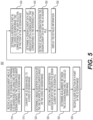
- FIG. 5 is a flowchart illustrating an exemplary method of identifying a design element in a 3D design file based on a user selection of a point in a 2D design image, according to one aspect of the present disclosure.
- the method 500 may be performed by the model-to-document linkage component 105 of the document review application 100.
- the model-to-document linkage component 105 may receive a 2D design document and a 3D design file.
- the 2D design document may comprise a 2D design image 230 while the 3D design file may comprise a 3D design model 210.
- the 3D design file may comprise a 3D design model 210 including one or more design elements, and information pertaining to each of the one or more design elements stored as a design element data set 250.
- the model-to-document linkage component 105 may convert the 3D design model 210 to a coded 2D design image 220.
- the coded 2D design image 220 may comprise one or more coded 2D design elements corresponding to the one or more design elements in the 3D design model 210.
- the coded 2D design image 220 may be color-coded, meaning the one or more coded 2D design elements therein may be color-coded.
- each of the one or more coded 2D design elements may be coded using any indicator that uniquely identifies the corresponding 2D design element, such as, e.g., patterns, shapes, tags, alphanumeric or other characters, tooltips, symbols, etc.
- the model-to-document linkage component 105 may determine a unique identifier for each of the one or more design elements in the 3D design model 210 based on the coded 2D design image.
- the model-to-document linkage component 105 may determine a unique identifier for each of the one or more design elements in the 3D design model 210 based on a code (e.g., color) of a coded 2D design element (e.g., color-coded 2D design element) that corresponds to the respective design element.
- the model-to-document linkage component 105 may store each generated unique identifier in association with the respective design element in the 3D design file (e.g., unique identifier 242 in FIG. 2C ).
- the model-to-document linkage component 105 may determine an alignment between the 2D design image 230 and the coded 2D design image 220. The alignment data 225 may be stored for use in the subsequent steps of the method 500.
- the model-to-document linkage component 105 may receive a user selection of a point in the 2D design image 230.
- the model-to-document linkage component 105 may receive user selection of a design element or a region enclosing one or more design elements in the 2D design image 230 for which additional information is desired.
- the model-to-document linkage component 105 may determine a reference point in the coded 2D design image 220 that corresponds to the user selection of the point (i.e., that corresponds to the user-selected point) in the 2D design image 230.
- the determination of the reference point may be based on the alignment between the 2D design image 230 and the coded 2D design image 220 (e.g., based on the alignment data 225).
- the determination of the reference point in the coded 2D design image 220 may equate to a determination of a coded 2D design element that lines up with the reference point (i.e., that is beneath the reference point) in the coded 2D design image 220.
- the model-to-document linkage component 105 may determine a design element data set associated with a design element, in the 3D deign file, that corresponds to the reference point (i.e., corresponds the coded 2D design element that lines up with the reference point in the coded 2D design image 220).
- the design element data set may be identified based on a color of the coded 2D design element (e.g., color-coded 2D design element) that corresponds to the reference point. For example, an RGB value of the color-coded 2D design element may be used to identify a matching unique identifier stored in die design element data set.
- the model-to-document linkage component 105 may retrieve detailed information from the design element data set in the 3D design file.
- the model-to-document linkage component 105 may display the retrieved detailed information in the document review application 100.
- the retrieved detailed information may also be used to search for additional design elements in the 2D design image 230 or the 3D design file, the additional design elements being related to or having similar characteristics as the design element for which the detailed information has been retrieved.
- the design element for which the detailed information has been retrieved is a particular type of door (i.e., a door associated with a particular set of properties)
- the user may be able to submit a query to search for all doors that have characteristics similar or equal to that door in the 2D design image 230 and/or the 3D design file.
- the user may be able to select a certain property displayed in the detailed information window 255, and the selection may result in one or more other design elements associated with the selected property being highlighted or visually distinguished in the 2D design image 230.
- processor may refer to any device or portion of a device that processes electronic data, e.g., from registers and/or memory to transform that electronic data into other electronic data that, e.g., may be stored in registers and/or memory.
- a "computer,” a “computing machine,” a “computing platform,” a “computing device,” or a “server” may include one or more processors.
- FIG. 6 illustrates an implementation of a computer system that may execute techniques presented herein.
- the computer system 600 can include a set of instructions that can be executed to cause the computer system 600 to perform any one or more of the methods or computer based functions disclosed herein.
- the computer system 600 may operate as a standalone device or may be connected, e.g., using a network, to other computer systems or peripheral devices.
- the computer system 600 may operate in the capacity of a server or as a client user computer in a server-client user network environment, or as a peer computer system in a peer-to-peer (or distributed) network environment.
- the computer system 600 can also be implemented as or incorporated into various devices, such as a personal computer (PC), a tablet PC, a set-top box (STB), a personal digital assistant (PDA), a mobile device, a palmtop computer, a laptop computer, a desktop computer, a communications device, a wireless telephone, a land-line telephone, a control system, a camera, a scanner, a facsimile machine, a printer, a pager, a personal trusted device, a web appliance, a network router, switch or bridge, or any other machine capable of executing a set of instructions (sequential or otherwise) that specify actions to be taken by that machine.
- the computer system 600 can be implemented using electronic devices that provide voice, video, or data communication. Further, while a single computer system 600 is illustrated, the term "system” shall also be taken to include any collection of systems or sub-systems that individually or jointly execute a set, or multiple sets, of instructions to perform one or more computer functions.
- the computer system 600 may include a processor 602, e.g., a central processing unit (CPU), a graphics processing unit (GPU), or both.
- the processor 602 may be a component in a variety of systems.
- the processor 602 may be part of a standard personal computer or a workstation.
- the processor 602 may be one or more general processors, digital signal processors, application specific integrated circuits, field programmable gate arrays, servers, networks, digital circuits, analog circuits, combinations thereof, or other now known or later developed devices for analyzing and processing data.
- the processor 602 may implement a software program, such as code generated manually (i.e., programmed).
- the computer system 600 may include a memory 604 that can communicate via a bus 608.
- the memory 604 may be a main memory, a static memory, or a dynamic memory.
- the memory 604 may include, but is not limited to computer readable storage media such as various types of volatile and non-volatile storage media, including but not limited to random access memory, read-only memory, programmable read-only memory, electrically programmable read-only memory, electrically erasable read-only memory, flash memory, magnetic tape or disk, optical media and the like.
- the memory 604 includes a cache or random-access memory for the processor 602.
- the memory 604 is separate from die processor 602, such as a cache memory of a processor, the system memory, or other memory.
- the memory 604 may be an external storage device or database for storing data. Examples include a hard drive, compact disc (“CD”), digital video disc (“DVD”), memory card, memory stick, floppy disc, universal serial bus (“USB”) memory device, or any other device operative to store data.
- the memory 604 is operable to store instructions executable by the processor 602.
- the functions, acts or tasks illustrated in the figures or described herein may be performed by the programmed processor 602 executing the instructions stored in the memory 604.
- the functions, acts or tasks are independent of the particular type of instructions set, storage media, processor or processing strategy and may be performed by software, hardware, integrated circuits, firmware, micro-code and the like, operating alone or in combination.
- processing strategies may include multiprocessing, multitasking, parallel processing and the like.
- the computer system 600 may further include a display unit 610, such as a liquid crystal display (LCD), an organic light emitting diode (OLED), a flat panel display, a solid-state display, a cathode ray tube (CRT), a projector, a printer or other now known or later developed display device for outputting determined information.
- a display unit 610 such as a liquid crystal display (LCD), an organic light emitting diode (OLED), a flat panel display, a solid-state display, a cathode ray tube (CRT), a projector, a printer or other now known or later developed display device for outputting determined information.
- the display 610 may act as an interface for the user to see the functioning of the processor 602, or specifically as an interface with the software stored in the memory 604 or in the drive unit 606.
- the computer system 600 may include an input device 612 configured to allow a user to interact with any of the components of system 600.
- the input device 612 may be a number pad, a keyboard, or a cursor control device, such as a mouse, or a joystick, touch screen display, remote control, or any other device operative to interact with the computer system 600.
- the computer system 600 may also or alternatively include a disk or optical drive unit 606.
- the disk drive unit 606 may include a computer-readable medium 622 in which one or more sets of instructions 624, e.g. software, can be embedded. Further, the instructions 624 may embody one or more of the methods or logic as described herein. The instructions 624 may reside completely or partially within the memory 604 and/or within the processor 602 during execution by the computer system 600.
- the memory 604 and the processor 602 also may include computer-readable media as discussed above.
- a computer-readable medium 622 includes instructions 624 or receives and executes instructions 624 responsive to a propagated signal so that a device connected to a network 626 can communicate voice, video, audio, images, or any other data over the network 626. Further, the instructions 624 may be transmitted or received over the network 626 via a communication port or interface 620, and/or using a bus 608.
- the communication port or interface 620 may be a part of the processor 602 or may be a separate component.
- the communication port 620 may be created in software or may be a physical connection in hardware.
- the communication port 620 may be configured to connect with a network 626, external media, the display 610, or any other components in system 600, or combinations thereof.
- connection with the network 626 may be a physical connection, such as a wired Ethernet connection or may be established wirelessly as discussed below.
- additional connections with other components of the system 600 may be physical connections or may be established wirelessly.
- the network 626 may alternatively be directly connected to die bus 608.
- While the computer-readable medium 622 is shown to be a single medium, the term “computer-readable medium” may include a single medium or multiple media, such as a centralized or distributed database, and/or associated caches and servers that store one or more sets of instructions.
- the term “computer-readable medium” may also include any medium that is capable of storing, encoding, or carrying a set of instructions for execution by a processor or that cause a computer system to perform any one or more of the methods or operations disclosed herein.
- the computer-readable medium 622 may be non-transitory, and may be tangible.
- the computer-readable medium 622 can include a solid-state memory such as a memory card or other package that houses one or more non-volatile read-only memories.
- the computer-readable medium 622 can be a random-access memory or other volatile rewritable memory. Additionally or alternatively, the computer-readable medium 622 can include a magneto-optical or optical medium, such as a disk or tapes or other storage device to capture carrier wave signals such as a signal communicated over a transmission medium.
- a digital file attachment to an e-mail or other self-contained information archive or set of archives may be considered a distribution medium that is a tangible storage medium. Accordingly, the disclosure is considered to include any one or more of a computer-readable medium or a distribution medium and other equivalents and successor media, in which data or instructions may be stored.
- dedicated hardware implementations such as application specific integrated circuits, programmable logic arrays and other hardware devices, can be constructed to implement one or more of the methods described herein.
- Applications that may include the apparatus and systems of various implementations can broadly include a variety of electronic and computer systems.
- One or more implementations described herein may implement functions using two or more specific interconnected hardware modules or devices with related control and data signals that can be communicated between and through the modules, or as portions of an application-specific integrated circuit. Accordingly, the present system encompasses software, firmware, and hardware implementations.
- the computer system 600 may be connected to one or more networks 626.
- the network 626 may define one or more networks including wired or wireless networks.
- the wireless network may be a cellular telephone network, an 802.11, 802.16, 802.20, or WiMax network.
- such networks may include a public network, such as the Internet, a private network, such as an intranet, or combinations thereof, and may utilize a variety of networking protocols now available or later developed including, but not limited to TCP/IP based networking protocols.
- the network 626 may include wide area networks (WAN), such as the Internet, local area networks (LAN), campus area networks, metropolitan area networks, a direct connection such as through a Universal Serial Bus (USB) port, or any other networks that may allow for data communication.
- WAN wide area networks
- LAN local area networks
- USB Universal Serial Bus
- the network 626 may be configured to couple one computing device to another computing device to enable communication of data between the devices.
- the network 626 may generally be enabled to employ any form of machine-readable media for communicating information from one device to another.
- the network 626 may include communication methods by which information may travel between computing devices.
- the network 626 may be divided into sub-networks. The sub-networks may allow access to all of the other components connected thereto or the sub-networks may restrict access between the components.
- the network 626 may be regarded as a public or private network connection and may include, for example, a virtual private network or an encryption or other security mechanism employed over the public Internet, or the like.
- the methods described herein may be implemented by software programs executable by a computer system.
- implementations can include distributed processing, component/object distributed processing, and parallel processing.
- virtual computer system processing can be constructed to implement one or more of the methods or functionality as described herein.
- an element described herein of an apparatus embodiment is an example of a means for carrying out the function performed by the element for the purpose of carrying out the invention.
- Coupled when used in the claims, should not be interpreted as being limited to direct connections only.
- the terms “coupled” and “connected,” along with their derivatives, may be used. It should be understood that these terms are not intended as synonyms for each other.
- the scope of the expression a device A coupled to a device B should not be limited to devices or systems wherein an output of device A is directly connected to an input of device B. It means that there exists a path between an output of A and an input of B which may be a path including other devices or means.
- Coupled may mean that two or more elements are either in direct physical or electrical contact, or that two or more elements are not in direct contact with each other but yet still co-operate or interact with each other.
Landscapes
- Engineering & Computer Science (AREA)
- Physics & Mathematics (AREA)
- Geometry (AREA)
- Theoretical Computer Science (AREA)
- General Physics & Mathematics (AREA)
- Computer Hardware Design (AREA)
- General Engineering & Computer Science (AREA)
- Mathematical Analysis (AREA)
- Architecture (AREA)
- Computational Mathematics (AREA)
- Mathematical Optimization (AREA)
- Pure & Applied Mathematics (AREA)
- Evolutionary Computation (AREA)
- Civil Engineering (AREA)
- Structural Engineering (AREA)
- Software Systems (AREA)
- Human Computer Interaction (AREA)
- Computer Graphics (AREA)
- Processing Or Creating Images (AREA)
Claims (16)
- Verfahren zur Verknüpfung eines zweidimensionalen (2D) Designbildes mit einem dreidimensionalen (3D) Designmodell, umfassend:Empfangen eines 2D-Designdokuments und einer 3D-Designdatei, wobei das 2D-Designdokument ein 2D-Designbild umfasst und die 3D-Designdatei ein 3D-Designmodell umfasst, das ein oder mehrere Designelemente beinhaltet;Umwandeln des 3D-Designmodells in ein codiertes 2D-Designbild, wobei das codierte 2D-Designbild ein oder mehrere codierte 2D-Designelemente umfasst, die dem einen oder den mehreren Designelementen entsprechen;Bestimmen einer eindeutigen Kennung für jedes von dem einen oder den mehreren Designelementen basierend auf einem Code eines codierten 2D-Designelements von dem einen oder den mehreren codierten 2D-Designelementen, wobei der Code einem Designelement von dem einen oder den mehreren Designelementen entspricht;Speichern jeder eindeutigen Kennung in Verbindung mit dem jeweiligen Designelement in der 3D-Designdatei;Bestimmen einer Ausrichtung zwischen dem 2D-Designbild und dem codierten 2D-Designbild;Empfangen einer Benutzerauswahl eines Punktes in dem 2D-Designbild;Bestimmen eines Referenzpunktes in dem codierten 2D-Designbild, welcher der Benutzerauswahl des Punktes in dem 2D-Designbild entspricht; undBestimmen eines Designelementdatensatzes, der einem Designelement zugeordnet ist, das dem Referenzpunkt entspricht, wobei der Designelementdatensatz in der 3D-Designdatei gespeichert ist.
- Verfahren nach Anspruch 1, ferner umfassend:Abrufen von zusätzlichen Informationen aus dem Designelementdatensatz; undAnzeigen der zusätzlichen Informationen.
- Verfahren nach Anspruch 1, wobei der Code des codierten 2D-Designelements die Farbe des codierten 2D-Designelements ist.
- Verfahren nach Anspruch 1, wobei das Bestimmen des Designelementdatensatzes, der dem Designelement zugeordnet ist, das dem Referenzpunkt entspricht, auf einem Code eines codierten 2D-Designelements basiert, das dem Referenzpunkt entspricht.
- Verfahren nach Anspruch 4, wobei das Bestimmen des Designelementdatensatzes, der dem Designelement zugeordnet ist, das dem Referenzpunkt entspricht, ferner Folgendes umfasst:Bestimmen eines RGB-Wertes der Farbe des Referenzpunktes;Bestimmen einer eindeutigen Kennung aus einer oder mehreren eindeutigen Kennungen, die in der 3D-Designdatei gespeichert sind, die dem RGB-Wert entspricht; undBestimmen eines Designelementdatensatzes, welcher der eindeutigen Kennung zugeordnet ist.
- Verfahren nach Anspruch 1, wobei das eine oder die mehreren Designelemente 3D-Designelemente sind.
- Verfahren nach Anspruch 6, wobei das Umwandeln des 3D-Designmodells in das codierte 2D-Designbild Folgendes umfasst:Projizieren des einen oder der mehreren 3D-Designelemente auf ein oder mehrere 2D-Designelemente; undFarbcodieren von jedem von dem einen oder den mehreren 2D-Designelementen.
- Verfahren nach Anspruch 1, wobei das Bestimmen der eindeutigen Kennung für jedes von dem einen oder den mehreren Designelementen basierend auf dem Code des codierten 2D-Designelements von dem einen oder den mehreren codierten 2D-Designelementen Folgendes umfasst:Bestimmen eines RGB-Wertes der Farbe des codierten 2D-Designelements von dem einen oder den mehreren codierten 2D-Designelementen; undFestlegen des RGB-Wertes als eindeutige Kennung für das jeweilige Designelement.
- Verfahren nach Anspruch 1, wobei das Speichern jeder eindeutigen Kennung in Verbindung mit dem jeweiligen Designelement in der 3D-Designdatei Folgendes umfasst:
Speichern der eindeutigen Kennung in dem Designelementdatensatz, der dem Designelement zugeordnet ist. - Verfahren nach Anspruch 1, wobei das Bestimmen des Referenzpunktes in dem codierten 2D-Designbild, welcher der Benutzerauswahl des Punktes in dem 2D-Designbild entspricht, auf der Ausrichtung zwischen dem 2D-Designbild und dem codierten 2D-Designbild basiert.
- Verfahren nach Anspruch 1, ferner umfassend:Empfangen einer Benutzerauswahl einer Region in dem 2D-Designbild;Bestimmen einer Referenzregion in dem codierten 2D-Designbild, die der von dem Benutzer ausgewählten Region in dem 2D-Designbild entspricht; undBestimmen von einem oder mehreren Designelementen, die der Referenzregion entsprechen, basierend auf einem oder mehreren Indikatoren der Referenzregion.
- Verfahren nach Anspruch 1, wobei die 3D-Designdatei eine Building-Information-Model(BIM-)Datei ist.
- Verfahren nach Anspruch 1, wobei das 2D-Designdokument eine Portable-Document-Format(PDF-)Datei ist oder eines von Folgendem ist: einer Architekturzeichnung, einer technischen Zeichnung und einer Konstruktionszeichnung.
- Verfahren nach Anspruch 1, wobei der Designelementdatensatz einen Designelementidentifikationsdatensatz und einen Designelementeigenschaftsdatensatz umfasst.
- System zur Verknüpfung eines zweidimensionalen (2D) Designbildes mit einem dreidimensionalen (3D) Designmodell, wobei das System Folgendes umfasst:einen oder mehrere Prozessoren; undeine oder mehrere Speichervorrichtungen, die Anweisungen speichern, die, wenn sie durch den einen oder die mehreren Prozessoren ausgeführt werden, den einen oder die mehreren Prozessoren veranlassen, das Verfahren nach Anspruch 1, 4 oder 5 durchzuführen.
- Nichtflüchtiges computerlesbares Medium zur Verknüpfung eines zweidimensionalen (2D) Designbildes mit einem dreidimensionalen (3D) Designmodell, wobei das nichtflüchtige computerlesbare Medium Anweisungen speichert, die, wenn sie durch einen oder mehrere Prozessoren ausgeführt werden, den einen oder die mehreren Prozessoren veranlassen, das Verfahren nach Anspruch 1 oder Anspruch 2 durchzuführen.
Priority Applications (1)
| Application Number | Priority Date | Filing Date | Title |
|---|---|---|---|
| EP24194691.2A EP4438275A3 (de) | 2019-06-06 | 2020-06-05 | Verfahren und systeme zur herstellung einer verknüpfung zwischen einer dreidimensionalen elektronischen designdatei und einem zweidimensionalen designdokument |
Applications Claiming Priority (2)
| Application Number | Priority Date | Filing Date | Title |
|---|---|---|---|
| US201962858110P | 2019-06-06 | 2019-06-06 | |
| PCT/US2020/036370 WO2020247783A1 (en) | 2019-06-06 | 2020-06-05 | Methods and systems for establishing a linkage between a three-dimensional electronic design file and a two-dimensional design document |
Related Child Applications (2)
| Application Number | Title | Priority Date | Filing Date |
|---|---|---|---|
| EP24194691.2A Division-Into EP4438275A3 (de) | 2019-06-06 | 2020-06-05 | Verfahren und systeme zur herstellung einer verknüpfung zwischen einer dreidimensionalen elektronischen designdatei und einem zweidimensionalen designdokument |
| EP24194691.2A Division EP4438275A3 (de) | 2019-06-06 | 2020-06-05 | Verfahren und systeme zur herstellung einer verknüpfung zwischen einer dreidimensionalen elektronischen designdatei und einem zweidimensionalen designdokument |
Publications (3)
| Publication Number | Publication Date |
|---|---|
| EP3980253A1 EP3980253A1 (de) | 2022-04-13 |
| EP3980253A4 EP3980253A4 (de) | 2023-07-05 |
| EP3980253B1 true EP3980253B1 (de) | 2024-09-25 |
Family
ID=73651594
Family Applications (2)
| Application Number | Title | Priority Date | Filing Date |
|---|---|---|---|
| EP20819323.5A Active EP3980253B1 (de) | 2019-06-06 | 2020-06-05 | Verfahren und systeme zur herstellung einer verknüpfung zwischen einer dreidimensionalen elektronischen designdatei und einem zweidimensionalen designdokument |
| EP24194691.2A Pending EP4438275A3 (de) | 2019-06-06 | 2020-06-05 | Verfahren und systeme zur herstellung einer verknüpfung zwischen einer dreidimensionalen elektronischen designdatei und einem zweidimensionalen designdokument |
Family Applications After (1)
| Application Number | Title | Priority Date | Filing Date |
|---|---|---|---|
| EP24194691.2A Pending EP4438275A3 (de) | 2019-06-06 | 2020-06-05 | Verfahren und systeme zur herstellung einer verknüpfung zwischen einer dreidimensionalen elektronischen designdatei und einem zweidimensionalen designdokument |
Country Status (5)
| Country | Link |
|---|---|
| US (4) | US11468208B2 (de) |
| EP (2) | EP3980253B1 (de) |
| AU (2) | AU2020288651B2 (de) |
| CA (1) | CA3139998A1 (de) |
| WO (1) | WO2020247783A1 (de) |
Families Citing this family (6)
| Publication number | Priority date | Publication date | Assignee | Title |
|---|---|---|---|---|
| US20220138492A1 (en) | 2020-10-30 | 2022-05-05 | Johnson Controls Technology Company | Data preprocessing and refinement tool |
| CN112668084A (zh) * | 2020-12-30 | 2021-04-16 | 晟通科技集团有限公司 | 模板编码方法、计算机装置及存储介质 |
| CN113538708B (zh) * | 2021-06-17 | 2023-10-31 | 上海建工四建集团有限公司 | 二维视图中对三维bim模型进行展示和交互的方法 |
| CN113761642B (zh) * | 2021-11-10 | 2022-03-15 | 北京建工集团有限责任公司 | 基于bim模型与图形码匹配的管道构件检测方法 |
| CN116069313A (zh) * | 2023-02-01 | 2023-05-05 | 北京尽微致广信息技术有限公司 | 一种图像和文档协同展示的方法、系统、设备及存储介质 |
| US12229480B1 (en) * | 2024-02-01 | 2025-02-18 | University Of Florida Research Foundation, Inc. | AI-assisted code compliance checking for building and land development |
Family Cites Families (34)
| Publication number | Priority date | Publication date | Assignee | Title |
|---|---|---|---|---|
| JP2005502111A (ja) * | 2001-08-31 | 2005-01-20 | ソリッドワークス コーポレイション | 2dおよび3dモデリングデータの同時使用法 |
| US7752065B2 (en) * | 2003-08-20 | 2010-07-06 | Leonard Buzz | Digital percent complete process |
| US7197735B2 (en) * | 2004-12-15 | 2007-03-27 | Lsi Logic Corporation | Floorplan visualization method using gate count and gate density estimations |
| US20070046695A1 (en) * | 2005-08-23 | 2007-03-01 | University Of Utah | System and method for computer aided design |
| US7801114B1 (en) * | 2005-10-26 | 2010-09-21 | At&T Intellectual Property Ii, L.P. | Method and apparatus for providing network based interior design application |
| US20090138113A1 (en) * | 2006-11-27 | 2009-05-28 | Designin Corporation | Systems, methods, and computer program products for home and landscape design |
| US20110078169A1 (en) * | 2008-05-05 | 2011-03-31 | Accela, Inc. | Electronic Blueprint Evaluation System For Approving Blueprints |
| US8514222B2 (en) | 2008-08-13 | 2013-08-20 | Autodesk, Inc. | Device, system, and method of computer aided design (CAD) |
| CN102317945A (zh) * | 2009-02-20 | 2012-01-11 | 太阳能公司 | 自动化太阳能收集器安装设计 |
| US9129438B2 (en) * | 2011-01-18 | 2015-09-08 | NedSense Loft B.V. | 3D modeling and rendering from 2D images |
| US8823744B2 (en) * | 2012-03-23 | 2014-09-02 | Bluebeam Software, Inc. | Method for indicating annotations associated with a particular display view of a three-dimensional model independent of any display view |
| US9519973B2 (en) * | 2013-09-08 | 2016-12-13 | Intel Corporation | Enabling use of three-dimensional locations of features images |
| US10430526B2 (en) * | 2014-02-18 | 2019-10-01 | Safaira, Inc. | Systems and methods for displaying impact analysis data while designing an architectural structure |
| US9782936B2 (en) * | 2014-03-01 | 2017-10-10 | Anguleris Technologies, Llc | Method and system for creating composite 3D models for building information modeling (BIM) |
| US20150302639A1 (en) * | 2014-03-26 | 2015-10-22 | Augmentecture, Inc. | Method and system for creating enhanced images including augmented reality features to be viewed on mobile devices with corresponding designs |
| US20160012160A1 (en) * | 2014-07-11 | 2016-01-14 | Graphisoft | Building model user interface and method of use |
| US9489597B2 (en) * | 2014-08-21 | 2016-11-08 | The Boeing Company | Visualization and analysis of a topical element of a complex system |
| US20210319601A1 (en) * | 2014-08-29 | 2021-10-14 | Eric Leininger | System and method for creating patent drawings |
| WO2016116877A1 (en) * | 2015-01-20 | 2016-07-28 | Illinois Tool Works, Inc. | Method, computer program product and apparatus for providing a building options configuration |
| US11263372B2 (en) * | 2016-03-07 | 2022-03-01 | Bricsys Nv | Method for providing details to a computer aided design (CAD) model, a computer program product and a server therefore |
| CN106354945A (zh) * | 2016-08-31 | 2017-01-25 | 天河大成建筑云科技(天津)有限公司 | 基于建筑信息模型轻量化二、三维工程资料动态关联的装置和方法 |
| US20180158239A1 (en) * | 2016-11-01 | 2018-06-07 | Purdue Research Foundation | Sketch-based 3d modeling system |
| WO2018175656A1 (en) * | 2017-03-21 | 2018-09-27 | Dominion Engineering, Inc. | Crowdsourced mapping of environmental hazards |
| US10872465B2 (en) * | 2017-05-02 | 2020-12-22 | General Electric Company | System and method for model drawing tool |
| US10755145B2 (en) * | 2017-07-07 | 2020-08-25 | Carnegie Mellon University | 3D spatial transformer network |
| US10930048B2 (en) * | 2017-09-25 | 2021-02-23 | Autodesk, Inc. | Three-dimensional generative design based on two-dimensional sketching |
| US10762250B2 (en) * | 2018-01-08 | 2020-09-01 | Nuvolo Technologies Corporation | Interpreter framework for a computer file |
| US11263360B2 (en) * | 2018-01-19 | 2022-03-01 | Autodesk, Inc. | Building information design synthesis (BIDS) |
| WO2020116222A1 (ja) * | 2018-12-04 | 2020-06-11 | 日本電信電話株式会社 | Ict資源管理装置、ict資源管理方法、および、ict資源管理プログラム |
| US10909698B2 (en) * | 2019-05-03 | 2021-02-02 | Procore Technologies, Inc. | Pattern matching tool |
| CN112534457B (zh) * | 2019-07-17 | 2024-10-01 | 株式会社爱世克私 | 设计支援装置以及设计支援方法 |
| US20210248917A1 (en) * | 2020-02-07 | 2021-08-12 | University-Industry Cooperation Group Of Kyung Hee University | Method and system of measuring spatial ability required for architecture or interior design |
| US12039231B2 (en) * | 2020-03-31 | 2024-07-16 | Augmentecture, Inc. | Method and apparatus utilizing augmented reality for design collaboration |
| US11436812B2 (en) * | 2020-05-29 | 2022-09-06 | Open Space Labs, Inc. | Machine learning based object identification using scaled diagram and three-dimensional model |
-
2020
- 2020-06-05 EP EP20819323.5A patent/EP3980253B1/de active Active
- 2020-06-05 CA CA3139998A patent/CA3139998A1/en active Pending
- 2020-06-05 US US16/893,471 patent/US11468208B2/en active Active
- 2020-06-05 AU AU2020288651A patent/AU2020288651B2/en active Active
- 2020-06-05 WO PCT/US2020/036370 patent/WO2020247783A1/en not_active Ceased
- 2020-06-05 EP EP24194691.2A patent/EP4438275A3/de active Pending
-
2022
- 2022-08-31 US US17/823,739 patent/US12045544B2/en active Active
-
2024
- 2024-06-20 US US18/748,838 patent/US20240338498A1/en active Pending
-
2025
- 2025-01-16 US US19/024,120 patent/US20250156594A1/en active Pending
- 2025-11-28 AU AU2025271527A patent/AU2025271527A1/en active Pending
Also Published As
| Publication number | Publication date |
|---|---|
| US20250156594A1 (en) | 2025-05-15 |
| AU2025271527A1 (en) | 2026-01-08 |
| US20240338498A1 (en) | 2024-10-10 |
| US12045544B2 (en) | 2024-07-23 |
| US11468208B2 (en) | 2022-10-11 |
| EP3980253A1 (de) | 2022-04-13 |
| US20220414280A1 (en) | 2022-12-29 |
| EP3980253A4 (de) | 2023-07-05 |
| WO2020247783A1 (en) | 2020-12-10 |
| US20200387643A1 (en) | 2020-12-10 |
| CA3139998A1 (en) | 2020-12-10 |
| AU2020288651B2 (en) | 2025-09-18 |
| AU2020288651A1 (en) | 2022-01-20 |
| EP4438275A3 (de) | 2024-12-18 |
| EP4438275A2 (de) | 2024-10-02 |
Similar Documents
| Publication | Publication Date | Title |
|---|---|---|
| US12045544B2 (en) | Methods and systems for establishing a linkage between a three-dimensional electronic design file and a two-dimensional design document | |
| US20230153618A1 (en) | Methods and systems for automatically detecting design elements in a two-dimensional design document | |
| US12236553B2 (en) | Methods and systems for processing images to perform automatic alignment of electronic images | |
| US20250078180A1 (en) | Media management system | |
| US20150193735A1 (en) | Project Management System Providing Digital Form-Based Inspections in the Field | |
| CN107004008A (zh) | 使用对不同的数据存储位置的自动化查询的相关文件识别 | |
| US9135234B1 (en) | Collaborative generation of digital content with interactive reports | |
| JP2009086952A (ja) | 情報処理システム及び情報処理プログラム | |
| US20150213158A1 (en) | System and method for creating a design for home improvements | |
| CN116882032B (zh) | 一种建筑设计图集数字化、可视化及其应用方法与装置 | |
| US20250131218A1 (en) | Ensuring remote access by a worker to a correct two-dimensional (2d) drawing | |
| WO2024242164A1 (ja) | 文書処理方法、文書処理システム、及び文書処理プログラム | |
| CN115396624A (zh) | 一种智能匹配背景音的数字会议管理系统 | |
| CN114935996A (zh) | 在线处理文档的方法、计算机设备、存储介质 | |
| Moh et al. | A Prototype for Visualized Architecture Knowledge Collaboration Services |
Legal Events
| Date | Code | Title | Description |
|---|---|---|---|
| STAA | Information on the status of an ep patent application or granted ep patent |
Free format text: STATUS: THE INTERNATIONAL PUBLICATION HAS BEEN MADE |
|
| PUAI | Public reference made under article 153(3) epc to a published international application that has entered the european phase |
Free format text: ORIGINAL CODE: 0009012 |
|
| STAA | Information on the status of an ep patent application or granted ep patent |
Free format text: STATUS: REQUEST FOR EXAMINATION WAS MADE |
|
| 17P | Request for examination filed |
Effective date: 20211123 |
|
| AK | Designated contracting states |
Kind code of ref document: A1 Designated state(s): AL AT BE BG CH CY CZ DE DK EE ES FI FR GB GR HR HU IE IS IT LI LT LU LV MC MK MT NL NO PL PT RO RS SE SI SK SM TR |
|
| DAV | Request for validation of the european patent (deleted) | ||
| DAX | Request for extension of the european patent (deleted) | ||
| REG | Reference to a national code |
Ref country code: DE Free format text: PREVIOUS MAIN CLASS: B29C0067000000 Ref country code: DE Ref legal event code: R079 Ref document number: 602020038418 Country of ref document: DE Free format text: PREVIOUS MAIN CLASS: B29C0067000000 Ipc: G06F0030120000 |
|
| A4 | Supplementary search report drawn up and despatched |
Effective date: 20230605 |
|
| RIC1 | Information provided on ipc code assigned before grant |
Ipc: B29C 67/00 20170101ALI20230530BHEP Ipc: G06F 30/13 20200101ALI20230530BHEP Ipc: G06F 111/02 20200101ALI20230530BHEP Ipc: G06T 17/00 20060101ALI20230530BHEP Ipc: G06F 30/12 20200101AFI20230530BHEP |
|
| GRAP | Despatch of communication of intention to grant a patent |
Free format text: ORIGINAL CODE: EPIDOSNIGR1 |
|
| STAA | Information on the status of an ep patent application or granted ep patent |
Free format text: STATUS: GRANT OF PATENT IS INTENDED |
|
| RIC1 | Information provided on ipc code assigned before grant |
Ipc: B29C 67/00 20170101ALI20240328BHEP Ipc: G06F 30/13 20200101ALI20240328BHEP Ipc: G06F 111/02 20200101ALI20240328BHEP Ipc: G06T 17/00 20060101ALI20240328BHEP Ipc: G06F 30/12 20200101AFI20240328BHEP |
|
| INTG | Intention to grant announced |
Effective date: 20240422 |
|
| GRAS | Grant fee paid |
Free format text: ORIGINAL CODE: EPIDOSNIGR3 |
|
| GRAA | (expected) grant |
Free format text: ORIGINAL CODE: 0009210 |
|
| STAA | Information on the status of an ep patent application or granted ep patent |
Free format text: STATUS: THE PATENT HAS BEEN GRANTED |
|
| P01 | Opt-out of the competence of the unified patent court (upc) registered |
Free format text: CASE NUMBER: APP_44361/2024 Effective date: 20240730 |
|
| AK | Designated contracting states |
Kind code of ref document: B1 Designated state(s): AL AT BE BG CH CY CZ DE DK EE ES FI FR GB GR HR HU IE IS IT LI LT LU LV MC MK MT NL NO PL PT RO RS SE SI SK SM TR |
|
| REG | Reference to a national code |
Ref country code: GB Ref legal event code: FG4D |
|
| REG | Reference to a national code |
Ref country code: CH Ref legal event code: EP |
|
| REG | Reference to a national code |
Ref country code: DE Ref legal event code: R096 Ref document number: 602020038418 Country of ref document: DE |
|
| REG | Reference to a national code |
Ref country code: SE Ref legal event code: TRGR |
|
| REG | Reference to a national code |
Ref country code: IE Ref legal event code: FG4D |
|
| REG | Reference to a national code |
Ref country code: LT Ref legal event code: MG9D |
|
| PG25 | Lapsed in a contracting state [announced via postgrant information from national office to epo] |
Ref country code: NO Free format text: LAPSE BECAUSE OF FAILURE TO SUBMIT A TRANSLATION OF THE DESCRIPTION OR TO PAY THE FEE WITHIN THE PRESCRIBED TIME-LIMIT Effective date: 20241225 |
|
| PG25 | Lapsed in a contracting state [announced via postgrant information from national office to epo] |
Ref country code: GR Free format text: LAPSE BECAUSE OF FAILURE TO SUBMIT A TRANSLATION OF THE DESCRIPTION OR TO PAY THE FEE WITHIN THE PRESCRIBED TIME-LIMIT Effective date: 20241226 Ref country code: FI Free format text: LAPSE BECAUSE OF FAILURE TO SUBMIT A TRANSLATION OF THE DESCRIPTION OR TO PAY THE FEE WITHIN THE PRESCRIBED TIME-LIMIT Effective date: 20240925 |
|
| PG25 | Lapsed in a contracting state [announced via postgrant information from national office to epo] |
Ref country code: BG Free format text: LAPSE BECAUSE OF FAILURE TO SUBMIT A TRANSLATION OF THE DESCRIPTION OR TO PAY THE FEE WITHIN THE PRESCRIBED TIME-LIMIT Effective date: 20240925 |
|
| PG25 | Lapsed in a contracting state [announced via postgrant information from national office to epo] |
Ref country code: LV Free format text: LAPSE BECAUSE OF FAILURE TO SUBMIT A TRANSLATION OF THE DESCRIPTION OR TO PAY THE FEE WITHIN THE PRESCRIBED TIME-LIMIT Effective date: 20240925 |
|
| PG25 | Lapsed in a contracting state [announced via postgrant information from national office to epo] |
Ref country code: RS Free format text: LAPSE BECAUSE OF FAILURE TO SUBMIT A TRANSLATION OF THE DESCRIPTION OR TO PAY THE FEE WITHIN THE PRESCRIBED TIME-LIMIT Effective date: 20241225 |
|
| REG | Reference to a national code |
Ref country code: NL Ref legal event code: MP Effective date: 20240925 |
|
| PG25 | Lapsed in a contracting state [announced via postgrant information from national office to epo] |
Ref country code: RS Free format text: LAPSE BECAUSE OF FAILURE TO SUBMIT A TRANSLATION OF THE DESCRIPTION OR TO PAY THE FEE WITHIN THE PRESCRIBED TIME-LIMIT Effective date: 20241225 Ref country code: NO Free format text: LAPSE BECAUSE OF FAILURE TO SUBMIT A TRANSLATION OF THE DESCRIPTION OR TO PAY THE FEE WITHIN THE PRESCRIBED TIME-LIMIT Effective date: 20241225 Ref country code: LV Free format text: LAPSE BECAUSE OF FAILURE TO SUBMIT A TRANSLATION OF THE DESCRIPTION OR TO PAY THE FEE WITHIN THE PRESCRIBED TIME-LIMIT Effective date: 20240925 Ref country code: GR Free format text: LAPSE BECAUSE OF FAILURE TO SUBMIT A TRANSLATION OF THE DESCRIPTION OR TO PAY THE FEE WITHIN THE PRESCRIBED TIME-LIMIT Effective date: 20241226 Ref country code: FI Free format text: LAPSE BECAUSE OF FAILURE TO SUBMIT A TRANSLATION OF THE DESCRIPTION OR TO PAY THE FEE WITHIN THE PRESCRIBED TIME-LIMIT Effective date: 20240925 Ref country code: BG Free format text: LAPSE BECAUSE OF FAILURE TO SUBMIT A TRANSLATION OF THE DESCRIPTION OR TO PAY THE FEE WITHIN THE PRESCRIBED TIME-LIMIT Effective date: 20240925 |
|
| REG | Reference to a national code |
Ref country code: AT Ref legal event code: MK05 Ref document number: 1727266 Country of ref document: AT Kind code of ref document: T Effective date: 20240925 |
|
| PG25 | Lapsed in a contracting state [announced via postgrant information from national office to epo] |
Ref country code: NL Free format text: LAPSE BECAUSE OF FAILURE TO SUBMIT A TRANSLATION OF THE DESCRIPTION OR TO PAY THE FEE WITHIN THE PRESCRIBED TIME-LIMIT Effective date: 20240925 |
|
| PG25 | Lapsed in a contracting state [announced via postgrant information from national office to epo] |
Ref country code: PT Free format text: LAPSE BECAUSE OF FAILURE TO SUBMIT A TRANSLATION OF THE DESCRIPTION OR TO PAY THE FEE WITHIN THE PRESCRIBED TIME-LIMIT Effective date: 20250127 Ref country code: IS Free format text: LAPSE BECAUSE OF FAILURE TO SUBMIT A TRANSLATION OF THE DESCRIPTION OR TO PAY THE FEE WITHIN THE PRESCRIBED TIME-LIMIT Effective date: 20250125 |
|
| PG25 | Lapsed in a contracting state [announced via postgrant information from national office to epo] |
Ref country code: RO Free format text: LAPSE BECAUSE OF FAILURE TO SUBMIT A TRANSLATION OF THE DESCRIPTION OR TO PAY THE FEE WITHIN THE PRESCRIBED TIME-LIMIT Effective date: 20240925 Ref country code: SM Free format text: LAPSE BECAUSE OF FAILURE TO SUBMIT A TRANSLATION OF THE DESCRIPTION OR TO PAY THE FEE WITHIN THE PRESCRIBED TIME-LIMIT Effective date: 20240925 |
|
| PG25 | Lapsed in a contracting state [announced via postgrant information from national office to epo] |
Ref country code: ES Free format text: LAPSE BECAUSE OF FAILURE TO SUBMIT A TRANSLATION OF THE DESCRIPTION OR TO PAY THE FEE WITHIN THE PRESCRIBED TIME-LIMIT Effective date: 20240925 |
|
| PG25 | Lapsed in a contracting state [announced via postgrant information from national office to epo] |
Ref country code: AT Free format text: LAPSE BECAUSE OF FAILURE TO SUBMIT A TRANSLATION OF THE DESCRIPTION OR TO PAY THE FEE WITHIN THE PRESCRIBED TIME-LIMIT Effective date: 20240925 Ref country code: EE Free format text: LAPSE BECAUSE OF FAILURE TO SUBMIT A TRANSLATION OF THE DESCRIPTION OR TO PAY THE FEE WITHIN THE PRESCRIBED TIME-LIMIT Effective date: 20240925 |
|
| PG25 | Lapsed in a contracting state [announced via postgrant information from national office to epo] |
Ref country code: CZ Free format text: LAPSE BECAUSE OF FAILURE TO SUBMIT A TRANSLATION OF THE DESCRIPTION OR TO PAY THE FEE WITHIN THE PRESCRIBED TIME-LIMIT Effective date: 20240925 Ref country code: PL Free format text: LAPSE BECAUSE OF FAILURE TO SUBMIT A TRANSLATION OF THE DESCRIPTION OR TO PAY THE FEE WITHIN THE PRESCRIBED TIME-LIMIT Effective date: 20240925 |
|
| PG25 | Lapsed in a contracting state [announced via postgrant information from national office to epo] |
Ref country code: SK Free format text: LAPSE BECAUSE OF FAILURE TO SUBMIT A TRANSLATION OF THE DESCRIPTION OR TO PAY THE FEE WITHIN THE PRESCRIBED TIME-LIMIT Effective date: 20240925 Ref country code: IT Free format text: LAPSE BECAUSE OF FAILURE TO SUBMIT A TRANSLATION OF THE DESCRIPTION OR TO PAY THE FEE WITHIN THE PRESCRIBED TIME-LIMIT Effective date: 20240925 |
|
| REG | Reference to a national code |
Ref country code: DE Ref legal event code: R097 Ref document number: 602020038418 Country of ref document: DE |
|
| PGFP | Annual fee paid to national office [announced via postgrant information from national office to epo] |
Ref country code: DE Payment date: 20250618 Year of fee payment: 6 |
|
| PG25 | Lapsed in a contracting state [announced via postgrant information from national office to epo] |
Ref country code: DK Free format text: LAPSE BECAUSE OF FAILURE TO SUBMIT A TRANSLATION OF THE DESCRIPTION OR TO PAY THE FEE WITHIN THE PRESCRIBED TIME-LIMIT Effective date: 20240925 |
|
| PGFP | Annual fee paid to national office [announced via postgrant information from national office to epo] |
Ref country code: GB Payment date: 20250618 Year of fee payment: 6 |
|
| PGFP | Annual fee paid to national office [announced via postgrant information from national office to epo] |
Ref country code: FR Payment date: 20250627 Year of fee payment: 6 |
|
| PGFP | Annual fee paid to national office [announced via postgrant information from national office to epo] |
Ref country code: SE Payment date: 20250618 Year of fee payment: 6 |
|
| PLBE | No opposition filed within time limit |
Free format text: ORIGINAL CODE: 0009261 |
|
| STAA | Information on the status of an ep patent application or granted ep patent |
Free format text: STATUS: NO OPPOSITION FILED WITHIN TIME LIMIT |
|
| 26N | No opposition filed |
Effective date: 20250626 |
|
| PG25 | Lapsed in a contracting state [announced via postgrant information from national office to epo] |
Ref country code: HR Free format text: LAPSE BECAUSE OF FAILURE TO SUBMIT A TRANSLATION OF THE DESCRIPTION OR TO PAY THE FEE WITHIN THE PRESCRIBED TIME-LIMIT Effective date: 20240925 |
|
| REG | Reference to a national code |
Ref country code: CH Ref legal event code: H13 Free format text: ST27 STATUS EVENT CODE: U-0-0-H10-H13 (AS PROVIDED BY THE NATIONAL OFFICE) Effective date: 20260127 |
|
| PG25 | Lapsed in a contracting state [announced via postgrant information from national office to epo] |
Ref country code: MC Free format text: LAPSE BECAUSE OF FAILURE TO SUBMIT A TRANSLATION OF THE DESCRIPTION OR TO PAY THE FEE WITHIN THE PRESCRIBED TIME-LIMIT Effective date: 20240925 |
|
| PG25 | Lapsed in a contracting state [announced via postgrant information from national office to epo] |
Ref country code: LU Free format text: LAPSE BECAUSE OF NON-PAYMENT OF DUE FEES Effective date: 20250605 |
|
| REG | Reference to a national code |
Ref country code: BE Ref legal event code: MM Effective date: 20250630 |
|
| PG25 | Lapsed in a contracting state [announced via postgrant information from national office to epo] |
Ref country code: IE Free format text: LAPSE BECAUSE OF NON-PAYMENT OF DUE FEES Effective date: 20250605 |
|
| PG25 | Lapsed in a contracting state [announced via postgrant information from national office to epo] |
Ref country code: BE Free format text: LAPSE BECAUSE OF NON-PAYMENT OF DUE FEES Effective date: 20250630 |
|
| PG25 | Lapsed in a contracting state [announced via postgrant information from national office to epo] |
Ref country code: CH Free format text: LAPSE BECAUSE OF NON-PAYMENT OF DUE FEES Effective date: 20250630 |