EP3980247B1 - Verfahren zur erzeugung eines strukturnetzes, verwendung eines strukturnetzes, computerprogramm und computerlesbares medium - Google Patents
Verfahren zur erzeugung eines strukturnetzes, verwendung eines strukturnetzes, computerprogramm und computerlesbares medium Download PDFInfo
- Publication number
- EP3980247B1 EP3980247B1 EP19761760.8A EP19761760A EP3980247B1 EP 3980247 B1 EP3980247 B1 EP 3980247B1 EP 19761760 A EP19761760 A EP 19761760A EP 3980247 B1 EP3980247 B1 EP 3980247B1
- Authority
- EP
- European Patent Office
- Prior art keywords
- mesh
- support
- build
- specimen
- volume
- Prior art date
- Legal status (The legal status is an assumption and is not a legal conclusion. Google has not performed a legal analysis and makes no representation as to the accuracy of the status listed.)
- Active
Links
Images



Classifications
-
- G—PHYSICS
- G06—COMPUTING OR CALCULATING; COUNTING
- G06F—ELECTRIC DIGITAL DATA PROCESSING
- G06F30/00—Computer-aided design [CAD]
- G06F30/20—Design optimisation, verification or simulation
- G06F30/23—Design optimisation, verification or simulation using finite element methods [FEM] or finite difference methods [FDM]
-
- G—PHYSICS
- G06—COMPUTING OR CALCULATING; COUNTING
- G06F—ELECTRIC DIGITAL DATA PROCESSING
- G06F30/00—Computer-aided design [CAD]
- G06F30/10—Geometric CAD
-
- B—PERFORMING OPERATIONS; TRANSPORTING
- B22—CASTING; POWDER METALLURGY
- B22F—WORKING METALLIC POWDER; MANUFACTURE OF ARTICLES FROM METALLIC POWDER; MAKING METALLIC POWDER; APPARATUS OR DEVICES SPECIALLY ADAPTED FOR METALLIC POWDER
- B22F10/00—Additive manufacturing of workpieces or articles from metallic powder
- B22F10/80—Data acquisition or data processing
-
- B—PERFORMING OPERATIONS; TRANSPORTING
- B33—ADDITIVE MANUFACTURING TECHNOLOGY
- B33Y—ADDITIVE MANUFACTURING, i.e. MANUFACTURING OF THREE-DIMENSIONAL [3D] OBJECTS BY ADDITIVE DEPOSITION, ADDITIVE AGGLOMERATION OR ADDITIVE LAYERING, e.g. BY 3D PRINTING, STEREOLITHOGRAPHY OR SELECTIVE LASER SINTERING
- B33Y50/00—Data acquisition or data processing for additive manufacturing
-
- G—PHYSICS
- G06—COMPUTING OR CALCULATING; COUNTING
- G06F—ELECTRIC DIGITAL DATA PROCESSING
- G06F2113/00—Details relating to the application field
- G06F2113/10—Additive manufacturing, e.g. three-dimensional [3D] printing
-
- Y—GENERAL TAGGING OF NEW TECHNOLOGICAL DEVELOPMENTS; GENERAL TAGGING OF CROSS-SECTIONAL TECHNOLOGIES SPANNING OVER SEVERAL SECTIONS OF THE IPC; TECHNICAL SUBJECTS COVERED BY FORMER USPC CROSS-REFERENCE ART COLLECTIONS [XRACs] AND DIGESTS
- Y02—TECHNOLOGIES OR APPLICATIONS FOR MITIGATION OR ADAPTATION AGAINST CLIMATE CHANGE
- Y02P—CLIMATE CHANGE MITIGATION TECHNOLOGIES IN THE PRODUCTION OR PROCESSING OF GOODS
- Y02P10/00—Technologies related to metal processing
- Y02P10/25—Process efficiency
Definitions
- the invention refers to a method for generating a structure mesh of a structure and simulating the additive manufacturing build-up process of the structure, wherein said structure mesh is to be build-up in a three-dimensional build-up volume in an additive manufacturing build-up process and which comprises at least one specimen and at least one support for supporting the at least one specimen on a boundary of the build-up volume, especially on a build-up platform which defines a lower part of a boundary of the build-up volume, wherein the structure mesh can be used in simulating the additive manufacturing build-up process of the structure.
- the invention also refers to a use of such a structure mesh.
- the invention refers to a computer program and a computer-readable medium.
- a large number of additive manufacturing build-up processes also known as generative manufacturing or 3D printing processes, are known for the fast and cost-effective production of both prototypes and end products.
- These processes which are summarized under the term rapid prototyping, enable in particular the direct production of individual specimens, also known as parts to print, on the basis of digital construction data, especially CAD data of the specimens.
- Production can be carried out using liquid, strip, wire or powder starting materials, which is why there are few restrictions with regard to the specimen geometries and specimen materials. Thanks to the layer-by-layer production, previously unattainable geometries can be produced with these processes.
- a metal powder to be processed is applied in a thin layer to a build-up platform and then completely melted locally using a laser radiation so that it forms a solid material layer after solidification.
- the build-up platform is then lowered by the amount of one layer thickness, metal powder is applied again and a laser beam is then directed over the new metal powder layer. This procedure is repeated until the desired specimen is completed.
- the SEBM process is almost identical to the SLM process, except that the metal powder is melted using an electron beam instead of laser radiation.
- a specimen that is build-up in a three-dimensional build-up volume may have to be supported by a support connected to a boundary of the build-up volume, especially a build-up volume platform which defines a lower boundary of the build-up volume.
- a support is used on the one hand to support areas if the specimen, such as areas of high overhang angles, typically lager than 45°.
- the support dissipates heat to the boundary of the build-up volume while the at least one specimen is build-up.
- a structure comprises the at least one specimen and the at least one support is build-up in the three-dimensional build-up volume in the additive manufacturing build-up process.
- Digital construction data, especially CAD data, for the at least one specimen are usually available such that at least one specimen mesh can be generated based on these digital construction data.
- data may already be available which represent the at least one specimen meshed with an exact tetrahedron mesh or with a mesh based on voxelization technique.
- an exact tetrahedron mesh the geometry of the at least one specimen is approximated quite accurately as compared to the voxelization technique which results in a relatively rough approximation of the geometry of the at least one specimen.
- the at least one support can have multiple shapes and structures and is usually relatively geometrically complex, especially compared with the at least one specimen.
- the at least one support is represented by surface data that describe a facetted surface of the at least one support.
- the facetted surface may consist of several facetted surface parts which are either connected to each other or separated from each other.
- the facetted surface may be formed by a plurality of triangles, for example.
- the surface data and the facetted surface are not meshable.
- the at least one support has to be treated and meshed as at least one solid structure and then a homogenized material may be used to correctly represent anisotropic behavior and at the same time have low degrees of freedom to have acceptable calculation times.
- the existing surface data that describe a facetted surface of the at least one support have to be converted into data of at least one solid geometry, i.e. volume data, that can be meshed.
- the generation of the solid geometry is done by extrusion of support faces and interpreting parameters, such as angled support information or distance to a build plate, of the facetted supports to a solid body.
- this "reverse engineering" approach is quite inrobust and often fails.
- only a few support types can be converted with the current method which is a large limitation of the actual simulation capabilities.
- shing often used in this context, means for example that a total area, i.e. either a surface or a volume, is divided into a finite number of subareas, i.e. discrete sections of the total area, also denoted as elements, and thus discretized.
- a volume can be divided into cuboids, hexahedra, pyramids or tetrahedral.
- the inventive method provides a meshing approach that resolves the problems associated with meshing the at least one support while maintaining the simulation accuracy in a later additive manufacturing build-up process simulation by keeping/using at least one specimen mesh which is usually a high quality mesh especially as a seed mesh.
- the seed mesh is preferably a two-dimensional seed mesh, especially a two-dimensional shell seed mesh, which can extend along at least one surface, such as a plane or a curved surface, in three-dimensional space.
- Using the at least one specimen surface mesh as a seed mesh results in nodes and edges of the part of the specimen surface mesh that represents the outer surface of the specimen to match background mesh nodes and background mesh edges at the outer boundary of the created background mesh.
- the structure mesh as a whole is generated in such a way that the at least one support mesh, the at least one specimen mesh and the at least one environment mesh are connected with each other so that two neighboring meshes share the same nodes at their interfaces in their transition area, the computational effort required for interconnecting the at least one support mesh, the at least one specimen mesh and the at least one environment mesh in state-of-the-art processes is no longer necessary.
- all different meshes are implicitly and consistently connected. There is for example no need to create any geometrical brep model for at least one support sub-volume and/or at least one environment sub-volume of the build-up volume and therefore no need to explicitly create connections between the different meshes which would lead to massive problems for complex geometric components.
- brep stands for "boundary representation” and brep models are known in the art.
- inventive method allows to robustly mesh any kind of structure that is to be build-up in an additive manufacturing build-up process and the environment surrounding the structure.
- supports that can be meshed with the inventive method are point supports, line supports, block supports, volume supports, cone supports, gusset supports, contour supports and web supports to name just a few.
- the additive manufacturing build-up process is a powder bed fusion based build-up process
- the environment mesh can be a powder mesh representing the powder used to build-up the structure.
- STL data means data in STL file format, wherein the abbreviation STL stands for "stereolithography”.
- the term "identifying” used in step d) may also be replaced by the term "capturing”.
- step b) comprises providing at least one three-dimensional specimen mesh which represents a discretization not only of the surface of the at least one specimen but of the entire volume of the at least one specimen
- step c) comprises discretizing the cavity with background mesh elements having the same size and/or shape as three-dimensional specimen mesh elements of the at least one three-dimensional specimen mesh
- step c) comprises creating a three-dimensional background mesh whose background mesh elements are tetrahedron-shaped, pyramid-shaped, hexahedron-shaped and/or cuboid-shaped.
- the three-dimensional specimen mesh elements and the three-dimensional background mesh elements may have any three-dimensional shape.
- Step c) may comprise creating a background mesh having smaller elements in a region of the build-up volume where the at least one support is expected to be located, in particular in a region defined by a geometrical bounding box that encloses the at least one support and comprises all elements thereof, and larger elements outside this region. In this way, regions that are primarily to be simulated later can be resolved higher than the remaining regions.
- the efficiency of the inventive method and the success of step d) in identifying/capturing well the geometrical shape and details of the at least one support directly depends on the size of the background mesh elements. If the background mesh elements are larger than a thickness of the at least one support, the at least one support might not be fully identified/captured. On the other hand, if the background mesh has more background mesh elements than needed to properly identify/capture the at least one support, the method will be unnecessarily costly in terms of computational time.
- step d) comprises identifying surfaces, in particular outer surfaces, of the at least one support within the background mesh by identifying points of intersection of the surfaces of the at least one support with background mesh edges, creating new nodes at the points of intersection, thus splitting the respective background mesh edges, and interconnecting at least some of the new nodes to create at least one support surface mesh.
- region(s) each background mesh node belongs an environment/powder region or a support region
- the background mesh edges of the background mesh whose background mesh nodes do not all belong to a common region are split.
- New nodes created by the split operations are therefore at the boundary of at least two regions and will be considered as belonging to the regions of both nodes of the initial edge. As a consequence, all resulting elements fully belong to one region.
- the resulting at least one support surface mesh follows well the support shapes, even for shapes that are far from any canonic shape, extruded shape or any relatively simple shape, and even if the at least one support is a very open structure, i.e. a structure without clear boundary walls. At least one support surface mesh is thus automatically connected to a specimen mesh and to the build volume surface mesh.
- the surfaces of the at least one support identified in step d) may be surfaces of a sub-volume of the build-up volume that represents the at least one support as simulated in contrast to the facetted surface of the at least one support described in the surface data, in particular STL data, and/or in contrast to the at least one support as actually build-up in the additive manufacturing build-up process.
- the sub-volume of the build-up volume that represents the at least one support as simulated is defined as the set of points within the build-up volume that are located at a distance inferior to a threshold D to the closest facet of the facetted surface of the at least one support described by the surface data.
- the sub-volume thus corresponds to the solid geometry that is used instead of the pure surface data to represent the at least one support in later simulations.
- the threshold D can be defined in various ways. In particular, the threshold D is chosen as the minimal distance such that any point located in the interior of the at least one support is at most at a distance d to the closest facet of the at least one support, wherein the value of d corresponds to the value of D.
- the at least one support is very regular, this choice may lead to a consistent volume region without any powder inclusion. If the threshold D is chosen too high, the later simulation of the at least one support becomes too inaccurate. On the other hand, if the threshold D is chosen too small, so-called bubble meshes may arise. For supports that have a closed boundary or a nearly closed boundary, i.e. a fragmented boundary or a boundary with holes, such as for example grid-type supports, the value for D may be chosen to be smaller as compared to supports that have an open or more open boundary to limit the volume of the resulting at least one support mesh. The consequence may be that environment bubble meshes may be created inside the at least one support region, but these may be eliminated as described below.
- Evaluating if a node is at a distance inferior to D to the at least one support structure may be accelerated by using spatial hashtables and/or RTrees.
- step d) comprises identifying an environment mesh, in particular a powder mesh, which is an environment bubble mesh enclosed in a support mesh, wherein the environment bubble mesh is eliminated by making it part of the support mesh in which it is enclosed. Additionally or alternatively it is possible that step d) comprises identifying a support mesh which is a support bubble mesh not connected to the at least one specimen nor a build-up volume boundary, wherein the support bubble mesh is eliminated by making it part of the at least one environment mesh.
- the support bubble mesh preferably is also not connected to another identified support mesh and thus fully enclosed in an environment mesh.
- the bubble meshes can also be described as defects to be eliminated.
- the bubble meshes may be caused, for example, by the threshold D being chosen too small.
- At least one resulting support mesh may be modified to eliminate any undesirable offset obtained by at least one of the above steps. This may be achieved by computing a new support mesh boundary that is located at a distance E inside the initial support mesh boundary.
- the value of E may correspond to the value of D mentioned above.
- the interior of the resulting mesh boundary may be the new support mesh. In this way, a support mesh is obtained that more exactly matches the at least one support.
- At least one resulting mesh may be improved to meet a predefined element quality and element size.
- the background mesh elements may be adapted by a mesh adaptation method, especially a local mesh adaptation method, in particular to obtain elements of the same size or at least substantially the same size and/or of good quality.
- a local mesh adaptation method may comprise applying local operations that replace a limited number of elements by other elements that altogether form a mesh of the same cavity as the initial elements but have a higher quality and/or a different size.
- At least one surface mesh is remeshed by replacing the at least one surface mesh with a new surface mesh of at least substantially uniform edge length.
- the at least one new surface mesh resulting from the remeshing is preferably used as seed mesh in generating new three-dimensional meshes, especially new tetrahedral meshes. In this way, elements of the same size or at least substantially the same size can be achieved.
- the interior of the at least one specimen defined by the at least one specimen surface mesh may be meshed, especially in accordance with a discretization that is extracted from existing CAD data of the at least one specimen.
- a support surface mesh created in step d) defines a closed volume
- this volume may be meshed by a volume meshing technique.
- the resulting entire support mesh may comprise pyramid-shaped, hexahedron-shaped, cuboid-shaped and/or tetrahedron-shaped mesh elements.
- the entire support mesh is a tetrahedral mesh.
- a support can be initially defined by a closed volume, e.g. closed faceting or brep solid geometry, it may be meshed by classical volume meshing techniques. Its volume may not be part of the background mesh and it may be meshed in the same way as a specimen. This offers the possibility to obtain meshes that very accurately represent given geometrical models for a specific support. In the extreme case where all supports initially receive a closed geometrical model, the at least one powder mesh can still be obtained without requiring a geometrical model for the powder region.
- the above mentioned meshing of the interior of the at least one specimen and/or of a closed volume defined by a support surface mesh may be performed after elimination of at least one bubble mesh and/or after improvement of a resulting mesh.
- the above mentioned meshing of the interior of the at least one specimen and/or of a closed volume defined by a support surface mesh may be the last step of the inventive method.
- the mesh elements of the at least one specimen mesh, the at least one support mesh, the structure mesh and/or the at least one environment mesh have the same size and/or shape.
- a structure mesh and an environment mesh can be generated automatically without a user having to actively intervene in the generation process, i.e. without the necessity of manual interaction.
- users do not have to interact during the mesh generation procedure, they do not need to have any detailed knowledge on the mesh generation procedure, and thus they do not have to be experts in the field of meshing techniques.
- the invention also regards a use of a structure mesh of a structure generated according to the inventive method for simulating, especially thermal, mechanical and/or thermos-mechanical simulating, an additive manufacturing build-up process, in particular a powder bed fusion based build-up process, of the structure.
- the invention furthermore regards a computer program comprising instructions which, when the program is executed by at least one computer, cause the at least one computer to carry out the inventive method.
- the invention regards a computer-readable medium comprising instructions which, when executed on at least one computer, cause the at least one computer to perform the steps of the inventive method.
- the computer-readable medium can be, for example, a CD-ROM or DVD or a USB or flash memory. It should be noted that a computer-readable medium should not be understood exclusively as a physical medium, but that such a medium can also exist in the form of a data stream and/or a signal representing a data stream.
- Figures 1-5 show a purely schematic illustration illustrating steps of a method according to a first embodiment of the present invention.
- Figure 1 shows an X-Z sectional view of a three-dimensional build-up volume 1 with a structure 2 in it, which has been build-up or is to be build-up by a powder bed based additive manufacturing build-up process which may be a selective laser melting, SLM, process.
- SLM selective laser melting
- a metal powder 3 to be processed is applied in a thin layer to a build-up platform 4 defining a lower part of a boundary 5 of the build-up volume 1 and then completely melted locally using a laser radiation so that it forms a solid material layer after solidification.
- the boundary 5 of the build-up volume 1 is partly shown in figures 1 and 5 , for example. For reasons of illustration, only four of the total of six boundary surfaces of the build-up volume 1 can be seen in these figures.
- the above mentioned procedure is repeated layer by layer until the desired structure 2 is completed.
- the structure 2 consists of two cuboid specimens 6a,b and a complex support arrangement 7 which comprises two nearly columnar supports 8 and supports the specimen 6b shown in figure 1 on the right on the build-up platform 4.
- the supports 8 thus each extend at a distance from each other between the build-up platform 4 and the specimen 6b and connect the build-up platform 4 with the specimen 6b.
- the other specimen 6a shown in figure 1 on the left is directly placed on the build-up platform 4 without using any supports 8.
- the method according to the first embodiment of the present invention is used to generate a structure mesh 9 of the structure 2.
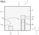
- the structure mesh 9 consists of two specimen meshes 9a and at least one support mesh 9b.
- a build-up volume surface mesh 10 that represents the boundary 5 of the three-dimensional build-up volume 1 is provided.
- two specimen surface meshes 11a,b each representing the outer surface of a corresponding specimen 6a,b are provided within an interior space surrounded by the build-up volume surface mesh 10.
- the specimen surface meshes 11a,b are based on available CAD data of the specimens 6a,b.
- a three-dimensional background mesh 12 is created in the cavity between the build-up volume surface mesh 10 and the two specimen surface meshes 11a,b using both specimen surface meshes 11a,b as two-dimensional seed meshes, as can be seen in figure 2 .
- the resulting background mesh 12 is composed of tetrahedron-shaped elements 13 consisting of background mesh nodes 14 and background mesh edges 15 extending between the background mesh nodes 14.
- the meshes are merely indicated by lines or squared areas. The squared areas are thus only intended to indicate that the respective area represents a mesh.
- both supports 8 only surface data, more specifically STL data, instead of CAD construction data are available. These surface data describe facetted surfaces 16 of the two supports 8 and have to be converted into data of at least one solid geometry, i.e. volume data, that can be meshed.
- two support meshes 9b and one environment mesh 17, in this example a powder mesh, which is defined by the background mesh 12 except for regions of the two support meshes 9b are identified using the background mesh 12 and the surface data of the supports 8. More precisely, surfaces 18 of the two supports 8 are identified within the background mesh 12 by identifying points of intersection 19 of the surfaces 18 of the two supports 8 with background mesh edges 15. At the points of intersection 19 new nodes are created and thus the respective background mesh edges 15 are split.
- the surfaces 18 that intersect the background mesh edges 15 are surfaces 18 of a sub-volume 20 of the build-up volume 1 that represents the two supports 8 as simulated later in contrast to the facetted surfaces 16 of the two supports 8 and/or in contrast to the supports 8 as actually build-up in the additive manufacturing build-up process.
- the sub-volume 20 is defined as the set of points within the build-up volume 1 that are located at a distance inferior to a threshold D to the closest facet of the facetted surfaces 16 of the two supports 8.
- the threshold D is chosen as the minimal distance such that any point located in the interior of the supports 8 is at most at a distance d to the closest facet of the facetted surfaces 16 of the two supports 8, wherein the value of d corresponds to the value of D.
- the sub-volume 20 and the threshold D are shown in figures 6 , 8 , 10 and 12 .
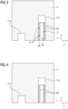
- four support meshes 9b and four environment meshes 17 are created, wherein two of the four support meshes 9b are support bubble meshes and three of the four environment meshes 17 are environment bubble meshes, as can be seen in figure 3 .
- the support bubble meshes 9b are fully enclosed in the environment mesh 17 which is no environment bubble mesh.
- the support bubble meshes 9b are neither connected to specimen 6b, nor to boundary 5, nor to another support mesh 9b.
- the environment bubble meshes 17 are each enclosed in one of the two support meshes 9b which are no support bubble meshes.
- the two support bubble meshes 9b are eliminated by making them part of the only environment mesh 17 which is not an environment bubble mesh.
- the three environment bubble meshes 17 are eliminated by making them part of the respective support mesh 9b in which they are enclosed.
- the result of this bubble elimination procedure is that only two support meshes 9b and one environment mesh 17 remain, which can be seen in figure 4 .
- the resulting meshes are improved to meet a predefined element quality and element size. More precisely, surface meshes made of boundaries of specimen, support and environment regions within the build-up volume 1 are remeshed. This is done by replacing a respective surface mesh, in particular a surface mesh between the support 8a and/or support 8b and the powder environment, with a new surface mesh of at least substantially uniform edge length. The new surface mesh resulting from the remeshing may than be used as a seed mesh in generating a corresponding new three-dimensional mesh. Additionally or alternatively, the background mesh elements 13 may be adapted by a common mesh adaptation method.
- the interior of the two specimens 6a,b defined by the specimen surface meshes 11a,b is meshed in accordance with a discretization that is extracted and/or taken over from the existing CAD data of the specimens 6a,b. Additionally or alternatively, if a support surface mesh of the support meshes 9a,b defines a closed volume, this closed volume may be meshed by a common volume meshing technique.
- the structure mesh 9 is thus generated in such a way that the two support meshes 9b, the two specimen meshes 9a and the environment mesh 17 are connected with each other so that two neighboring meshes share the same nodes at their interfaces in their transition area.
- the generated structure mesh 9 can be used for simulating, especially thermal, mechanical and/or thermos-mechanical simulating, the powder bed fusion based additive manufacturing build-up process of the structure 2. It should be clear that the embodiments of the inventive method described herein can also be used in conjunction with any other additive manufacturing build-up processes.
- Figure 6 shows a purely schematic illustration illustrating the step of identifying support meshes 9b of a method for generating a structure mesh 9 according to a second embodiment of the present invention.
- figure 6 represents an X-Z sectional view of a three-dimensional build-up volume 1.
- the method according to the second embodiment differs from the method according to the first embodiment only in that a different kind of support arrangement 7 is meshed, i.e. different support meshes 9b are identified.
- the support arrangement 7 in the second embodiment consists of a block support 8 shown on the left side in figure 6 and a line support 8 shown on the right side in figure 6 .
- FIG 7 Another kind of support arrangement 7 shown in figure 7 comprises a plurality of pipe-like supports 8 which can be seen as a grid-like structure in the section view of figure 8 .
- Yet another kind of support arrangement 7 shown in figure 9 comprises four parallel wall-like supports 8 which can be seen as four parallel lines 22 in the section view of figure 10 .
- Yet another kind of support arrangement 7 shown in figure 11 comprises five supports 8 in the form of parallel cylindrical columns which can be seen as five dots 23 in the section view of figure 12 .
- the distance i between two adjacent dots 23 is equal to the threshold D multiplied by cos (30°).
- the support arrangement 7 consisting of the supports 8 represented by facetted surfaces 16 is converted into a volume which is a sub-volume 20 of the build-up volume 1 and represents the support arrangement 7 as a solid body.
Landscapes
- Engineering & Computer Science (AREA)
- Physics & Mathematics (AREA)
- Theoretical Computer Science (AREA)
- General Physics & Mathematics (AREA)
- Geometry (AREA)
- Chemical & Material Sciences (AREA)
- Manufacturing & Machinery (AREA)
- Materials Engineering (AREA)
- Evolutionary Computation (AREA)
- Computer Hardware Design (AREA)
- General Engineering & Computer Science (AREA)
- Mathematical Optimization (AREA)
- Pure & Applied Mathematics (AREA)
- Mathematical Analysis (AREA)
- Computational Mathematics (AREA)
- Powder Metallurgy (AREA)
Claims (16)
- Computerimplementiertes Verfahren zur Erzeugung eines Strukturnetzes (9) einer Struktur (2) und Verwendung des Strukturnetzes (9) zum Simulieren eines additiven Fertigungsprozesses der Struktur (2),wobei das Strukturgeflecht (9) in einem dreidimensionalen Aufbauvolumen (1) in dem additiven Fertigungsprozess aufgebaut werden soll und mindestens eine Probe (6a,b) und mindestens einen Träger (8a,b) zum Abstützen der mindestens einen Probe (6a,b) an einer Begrenzung (5) des Aufbauvolumens (1) umfasst, dadurch gekennzeichnet, dassdas Verfahren die folgenden Schritte umfasst:a) Bereitstellen eines Aufbauvolumenoberflächennetzes (10), das eine Begrenzung (5) des dreidimensionalen Aufbauvolumens (1) darstellt;b) Bereitstellen mindestens eines Probennetzes (9a), das ein Probenoberflächennetz beinhaltet, das mindestens die Außenfläche einer entsprechenden Probe (6a,b) innerhalb eines von dem Aufbauvolumenoberflächennetz (10) umschlossenen Innenraums darstellt;c) Erzeugen eines dreidimensionalen Hintergrundnetzes (12) in dem Hohlraum zwischen dem Aufbauvolumenoberflächennetz (10) und dem mindestens einen Probenoberflächennetz (11a,b) unter Verwendung des mindestens einen Probenoberflächennetzes (11a,b) als Seed-Netz, wobei das Hintergrundnetz (12) aus Elementen (13) zusammengesetzt ist, die aus Hintergrundnetzknoten (14) und sich zwischen den Hintergrundnetzknoten (14) erstreckenden Hintergrundnetzkanten (15) bestehen;d) Identifizieren mindestens eines Stütznetzes (9b) und mindestens eines Umgebungsnetzes (17), welches durch das Hintergrundnetz (12) definiert ist, mit Ausnahme von Bereichen des mindestens einen Stütznetzes (9b) unter Verwendung des Hintergrundnetzes (12) und von Oberflächendaten, welche eine facettierte Oberfläche (16) des mindestens einen Trägers (8a,b) beschreiben, wobei das mindestens eine Stütznetz (9b) und das mindestens eine Probennetz (9a) zusammen das Strukturnetz (9) definieren, welches derart erzeugt wird, dass das mindestens eine Stütznetz (9b), das mindestens eine Probennetz (9a) und das mindestens eine Umgebungsnetz (17) so miteinander verbunden sind, dass sich zwei benachbarte Netze an ihren Grenzflächen in ihrem Übergangsbereich die gleichen Knoten teilen, wobei Schritt b) das Bereitstellen mindestens eines dreidimensionalen Probennetzes (9a) umfasst, das eine Diskretisierung nicht nur der Oberfläche der mindestens einen Probe (6a,b), sondern des gesamten Volumens der mindestens einen Probe (6a,b) darstellt, undwobei Schritt c) das Diskretisieren des Hohlraums mit Hintergrundnetzelementen (13) umfasst, die die gleiche Größe und/oder Form wie dreidimensionale Probennetzelemente des mindestens einen dreidimensionalen Probennetzes (9a) aufweisen.
- Verfahren nach Anspruch 1, wobei die Oberflächendaten Stereolithographiedaten sind.
- Verfahren nach Anspruch 1 oder 2,
dadurch gekennzeichnet, dass
der Schritt c) das Erzeugen eines dreidimensionalen Hintergrundnetzes (12) umfasst, dessen Hintergrundnetzelemente (13) tetraeder-, pyramiden-, hexaeder- und/oder quaderförmig ausgebildet sind. - Verfahren nach Anspruch 1, 2 oder 3,
dadurch gekennzeichnet, dass
der Schritt c) das Erzeugen eines Hintergrundnetzes (12) mit kleineren Elementen (13) in einem Bereich des Aufbauvolumens (1) umfasst, in dem sich der mindestens eine Träger (8a,b) voraussichtlich befinden wird, insbesondere in einem Bereich, der durch einen geometrischen Begrenzungsrahmen definiert ist, der den mindestens einen Träger (8a,b) umschließt und alle Elemente davon umfasst, und größere Elemente (13) außerhalb dieses Bereichs. - Verfahren nach einem der Ansprüche 1 bis 4,
dadurch gekennzeichnet, dass
Schritt d) das Identifizieren von Oberflächen (18), insbesondere von Außenflächen des mindestens einen Trägers (8a,b) innerhalb des Hintergrundnetzes (12) durch Identifizieren von Kreuzungspunkten (19) der Oberflächen (18) des mindestens einen Trägers (8a,b) mit Hintergrundnetzkanten (15) sowie das Erzeugen neuer Knoten an den Kreuzungspunkten (19), wodurch die jeweiligen Hintergrundnetzkanten (15) aufgeteilt werden, und das Verbinden von mindestens einigen der neuen Knoten, um mindestens ein Stützflächennetz zu erzeugen, umfasst. - Verfahren nach Anspruch 5,
dadurch gekennzeichnet, dass
die in Schritt d) identifizierten Oberflächen (18) des mindestens einen Trägers (8a,b) Oberflächen (18) eines Teilvolumens (20) des Aufbauvolumens (1) sind, welches den mindestens einen Träger (8a,b) als simuliert im Gegensatz zu dem mindestens einen Träger (8a,b) als tatsächlich in dem additiven Fertigungsprozess aufgebaut darstellt. - Verfahren nach Anspruch 6,
dadurch gekennzeichnet, dass
das Teilvolumen (20) des Aufbauvolumens (1), das den mindestens einen Träger (8a,b) als simuliert darstellt, als die Menge von Punkten innerhalb des Aufbauvolumens (1) definiert ist, die sich in einem Abstand befinden, der unterhalb einer Schwelle D zu der nächsten Facette der durch die Oberflächendaten beschriebenen facettierten Oberfläche (16) des mindestens einen Trägers (8a,b) liegt, wobei die Schwelle D vorzugsweise als minimaler Abstand so gewählt ist, dass jeder im Inneren des mindestens einen Trägers (8a,b) befindliche Punkt höchstens einen Abstand d zu der nächsten Facette des mindestens einen Trägers aufweist (8a,b), wobei der Wert von d dem Wert von D entspricht. - Verfahren nach einem der vorstehenden Ansprüche,
dadurch gekennzeichnet, dass
Schritt d) das Identifizieren eines Umgebungsnetzes (17) umfasst, insbesondere eines Pulvernetzes, welches ein in einem Stütznetz (9b) eingeschlossenes Umgebungsblasennetz ist, wobei das Umgebungsblasennetz (17) dadurch eliminiert wird, dass es zu einem Teil des Stütznetzes (9b) gemacht wird, in welchem es eingeschlossen ist, und/oder dass Schritt d) das Identifizieren eines Stütznetzes (9b) umfasst, welches ein nicht mit der mindestens einen Probe (6a,b) verbundenes Stützblasennetz oder eine Aufbauvolumengrenze (5) ist, wobei das Stützblasennetz (9b) dadurch eliminiert wird, dass es zu einem Teil des mindestens einen Umgebungsnetzes (17) gemacht wird. - Verfahren nach einem der vorstehenden Ansprüche,
dadurch gekennzeichnet, dass
insbesondere nach dem Entfernen von Blasennetzen mindestens ein resultierendes Netz verbessert wird, um eine vorgegebene Elementqualität und Elementgröße zu erfüllen. - Verfahren nach Anspruch 8,
dadurch gekennzeichnet, dass
die Hintergrundnetzelemente (13) durch ein Netzanpassungsverfahren, insbesondere ein lokales Netzanpassungsverfahren, adaptiert werden. - Verfahren nach Anspruch 8 oder 9,
dadurch gekennzeichnet, dass
mindestens ein Oberflächennetz (10, 11a,b), insbesondere Oberflächennetze (10, 11a,b) aus Begrenzungen von Proben-, Stütz- und Umgebungsbereichen innerhalb des Aufbauvolumens (1) durch Ersetzen des mindestens einen Oberflächennetzes (10, 11a,b) durch ein neues Oberflächennetz von zumindest im Wesentlichen einheitlicher Kantenlänge wieder vernetzt wird, wobei das aus der Neuvernetzung resultierende mindestens eine neue Oberflächennetz vorzugsweise als Seed-Netz zur Erzeugung neuer dreidimensionaler Netze verwendet wird. - Verfahren nach einem der vorstehenden Ansprüche,
dadurch gekennzeichnet, dass
das Innere der wenigstens einen durch das wenigstens eine Probenoberflächennetz (11a,b) definierten Probe (6a,b) vernetzt ist, insbesondere gemäß einer Diskretisierung, die aus vorhandenen CAD-Daten der wenigstens einen Probe (6a,b) extrahiert ist. - Verfahren nach einem der Ansprüche 5 bis 7 oder einem der Ansprüche 8 bis 12, falls auf Anspruch 5 zurückbezogen,
dadurch gekennzeichnet, dass
ein Stützflächennetz (9b) ein geschlossenes Volumen definiert, das durch eine Volumenvernetzungstechnik vernetzt wird. - Verwendung eines Strukturnetzes (9) einer Struktur (2), das gemäß einem Verfahren nach einem der vorstehenden Ansprüche erzeugt wurde, zur Simulation, insbesondere thermischen, mechanischen und/oder thermomechanischen Simulation, eines Aufbauprozesses der Struktur (2) für die additive Fertigung, insbesondere eines auf Pulverbettfusion basierenden Aufbauprozesses.
- Computerprogramm, umfassend Anweisungen, die bei Ausführung des Programms durch mindestens einen Computer den mindestens einen Computer dazu veranlassen, das Verfahren gemäß einem der vorstehenden Ansprüche durchzuführen.
- Computerlesbares Medium, umfassend Anweisungen, die, bei Ausführung auf mindestens einem Computer, den mindestens einen Computer dazu veranlassen, die Schritte des Verfahrens gemäß einem der Ansprüche 1 bis 13 auszuführen.
Applications Claiming Priority (1)
| Application Number | Priority Date | Filing Date | Title |
|---|---|---|---|
| PCT/EP2019/071822 WO2021028037A1 (en) | 2019-08-14 | 2019-08-14 | Method for generating a structure mesh, use of a structure mesh, computer program and computer-readable medium |
Publications (3)
| Publication Number | Publication Date |
|---|---|
| EP3980247A1 EP3980247A1 (de) | 2022-04-13 |
| EP3980247B1 true EP3980247B1 (de) | 2025-06-18 |
| EP3980247C0 EP3980247C0 (de) | 2025-06-18 |
Family
ID=67809422
Family Applications (1)
| Application Number | Title | Priority Date | Filing Date |
|---|---|---|---|
| EP19761760.8A Active EP3980247B1 (de) | 2019-08-14 | 2019-08-14 | Verfahren zur erzeugung eines strukturnetzes, verwendung eines strukturnetzes, computerprogramm und computerlesbares medium |
Country Status (4)
| Country | Link |
|---|---|
| US (1) | US20220414275A1 (de) |
| EP (1) | EP3980247B1 (de) |
| CN (1) | CN114222659B (de) |
| WO (1) | WO2021028037A1 (de) |
Families Citing this family (1)
| Publication number | Priority date | Publication date | Assignee | Title |
|---|---|---|---|---|
| CN118015223B (zh) * | 2024-04-09 | 2024-06-18 | 中国空气动力研究与发展中心计算空气动力研究所 | 三流形六面体网格生成方法及装置 |
Family Cites Families (10)
| Publication number | Priority date | Publication date | Assignee | Title |
|---|---|---|---|---|
| US8046097B2 (en) * | 2007-09-17 | 2011-10-25 | 3D Systems, Inc. | Region-based supports for parts produced by solid freeform fabrication |
| GB0719747D0 (en) * | 2007-10-10 | 2007-11-21 | Materialise Nv | Method and apparatus for automatic support generation for an object made by means of a rapid prototype production method |
| CN102279981B (zh) * | 2011-08-02 | 2013-04-24 | 北京农业信息技术研究中心 | 一种三维图像网格化方法 |
| EP3083198A1 (de) * | 2013-12-17 | 2016-10-26 | Renishaw Plc. | Verbesserungen beim oder im zusammenhang mit dem bau von trägern bei der additiven fertigung |
| US9902114B2 (en) * | 2014-01-09 | 2018-02-27 | Siemens Product Lifecycle Management Software Inc. | Method for creating three dimensional lattice structures in computer-aided design models for additive manufacturing |
| CN106132668B (zh) * | 2014-03-25 | 2018-05-15 | Dws有限公司 | 用于对借助于立体光刻工艺制造的对象的支承元件的开发点进行限定的改进的计算机实施方法 |
| US10409932B2 (en) * | 2014-09-19 | 2019-09-10 | Siemens Product Lifecyle Management Software Inc. | Computer-aided simulation of multi-layer selective laser sintering and melting additive manufacturing processes |
| EP3369014B1 (de) * | 2015-10-28 | 2021-11-03 | Siemens Industry Software Inc. | System und verfahren zur optimierung von werkzeugbahnen auf der basis von thermischen/strukturellen simulationen eines mit einem 3d-drucker hergestellten teils |
| EP3246831A1 (de) * | 2016-05-20 | 2017-11-22 | Dassault Systemes Simulia Corp. | Skalierbare finite-element-simulation von generativer fertigung |
| CN109571961B (zh) * | 2018-11-19 | 2021-01-15 | 上海理工大学 | 一种复杂非均质体参数化模型的切片及支撑点获取方法 |
-
2019
- 2019-08-14 WO PCT/EP2019/071822 patent/WO2021028037A1/en not_active Ceased
- 2019-08-14 US US17/634,957 patent/US20220414275A1/en active Pending
- 2019-08-14 CN CN201980099303.4A patent/CN114222659B/zh active Active
- 2019-08-14 EP EP19761760.8A patent/EP3980247B1/de active Active
Also Published As
| Publication number | Publication date |
|---|---|
| WO2021028037A1 (en) | 2021-02-18 |
| EP3980247A1 (de) | 2022-04-13 |
| CN114222659B (zh) | 2024-11-05 |
| US20220414275A1 (en) | 2022-12-29 |
| CN114222659A (zh) | 2022-03-22 |
| EP3980247C0 (de) | 2025-06-18 |
Similar Documents
| Publication | Publication Date | Title |
|---|---|---|
| Ibhadode et al. | Topology optimization for metal additive manufacturing: current trends, challenges, and future outlook | |
| US12111630B2 (en) | Method and system to generate three-dimensional meta-structure model of a workpiece | |
| US10748336B2 (en) | 3D finite element mesh of a 3D part that comprises a lattice structure | |
| EP3503040B1 (de) | Entwurf eines 3d-finite-element-netzes eines 3d-teils mit einer gitterstruktur | |
| US10802467B2 (en) | Methods of defining internal structures for additive manufacturing | |
| Keller et al. | Thermo-mechanical simulation of additive layer manufacturing of titanium aerospace structures | |
| WO2018045120A1 (en) | Improved additive manufacturing of a three-dimensional object | |
| CN108351906B (zh) | 用于具有晶格结构的部件的建模的系统和方法 | |
| US12282310B2 (en) | Dual lattice representation for simulation and manufacturing | |
| Moreira et al. | An accurate, adaptive and scalable parallel finite element framework for the part-scale thermo-mechanical analysis in metal additive manufacturing processes | |
| EP3980247B1 (de) | Verfahren zur erzeugung eines strukturnetzes, verwendung eines strukturnetzes, computerprogramm und computerlesbares medium | |
| EP4339898A2 (de) | System und verfahren zur erzeugung einer füllungsgeometrie eines körpers | |
| Ahmad et al. | Advances in additive manufacturing and its numerical modelling | |
| US20080100619A1 (en) | Mesh generation method and computer-readable article for executing the method | |
| US20180099358A1 (en) | Metallic Sleeve For Reducing Distortion In Additive Manufacturing | |
| Koch et al. | A CAD-based workflow and mechanical characterization for additive manufacturing of tailored lattice structures | |
| CN114556437A (zh) | 生成部件网格的方法、部件网格的使用方法、计算机程序和计算机可读介质 | |
| JP2021134385A (ja) | 積層造形方法、積層造形データの作成方法と作成プログラム、および積層造形システム | |
| Olleak et al. | Part-Scale Finite Element Modeling of the SLM Process with Layer-wise Adaptive Remeshing for Thermal History and Porosity Prediction | |
| CN110238400B (zh) | 一种基于三维成像技术和3d打印技术制备泡沫铝材料的方法 | |
| CN107273558A (zh) | 用于三维模型的机械性能校验的方法和装置 | |
| US20250367883A1 (en) | Lower-level finite element analysis mesh homogenization for simulation of additive manufacturing | |
| Martha et al. | Approaches for the Layer Data Generation for Special Additive Manufacturing Applications | |
| Sankar | Review and Development of Manufacturing Design Constraints for Topology-Optimized Parts in Investment casting | |
| Chalavadi | ADAPTIVE MESHING FRAMEWORK USING OCTREE DATA STRUCTURE FOR VOXEL BASED MESHES |
Legal Events
| Date | Code | Title | Description |
|---|---|---|---|
| STAA | Information on the status of an ep patent application or granted ep patent |
Free format text: STATUS: UNKNOWN |
|
| STAA | Information on the status of an ep patent application or granted ep patent |
Free format text: STATUS: THE INTERNATIONAL PUBLICATION HAS BEEN MADE |
|
| PUAI | Public reference made under article 153(3) epc to a published international application that has entered the european phase |
Free format text: ORIGINAL CODE: 0009012 |
|
| STAA | Information on the status of an ep patent application or granted ep patent |
Free format text: STATUS: REQUEST FOR EXAMINATION WAS MADE |
|
| 17P | Request for examination filed |
Effective date: 20220110 |
|
| AK | Designated contracting states |
Kind code of ref document: A1 Designated state(s): AL AT BE BG CH CY CZ DE DK EE ES FI FR GB GR HR HU IE IS IT LI LT LU LV MC MK MT NL NO PL PT RO RS SE SI SK SM TR |
|
| DAV | Request for validation of the european patent (deleted) | ||
| DAX | Request for extension of the european patent (deleted) | ||
| STAA | Information on the status of an ep patent application or granted ep patent |
Free format text: STATUS: EXAMINATION IS IN PROGRESS |
|
| 17Q | First examination report despatched |
Effective date: 20230217 |
|
| REG | Reference to a national code |
Ref country code: DE Ref legal event code: R079 Free format text: PREVIOUS MAIN CLASS: B29C0064386000 Ipc: G06F0030230000 Ref country code: DE Ref legal event code: R079 Ref document number: 602019071272 Country of ref document: DE Free format text: PREVIOUS MAIN CLASS: B29C0064386000 Ipc: G06F0030230000 |
|
| GRAP | Despatch of communication of intention to grant a patent |
Free format text: ORIGINAL CODE: EPIDOSNIGR1 |
|
| STAA | Information on the status of an ep patent application or granted ep patent |
Free format text: STATUS: GRANT OF PATENT IS INTENDED |
|
| INTG | Intention to grant announced |
Effective date: 20250325 |
|
| RIC1 | Information provided on ipc code assigned before grant |
Ipc: G06F 113/10 20200101ALI20250317BHEP Ipc: B33Y 50/00 20150101ALI20250317BHEP Ipc: G06F 30/23 20200101AFI20250317BHEP |
|
| GRAS | Grant fee paid |
Free format text: ORIGINAL CODE: EPIDOSNIGR3 |
|
| GRAA | (expected) grant |
Free format text: ORIGINAL CODE: 0009210 |
|
| STAA | Information on the status of an ep patent application or granted ep patent |
Free format text: STATUS: THE PATENT HAS BEEN GRANTED |
|
| AK | Designated contracting states |
Kind code of ref document: B1 Designated state(s): AL AT BE BG CH CY CZ DE DK EE ES FI FR GB GR HR HU IE IS IT LI LT LU LV MC MK MT NL NO PL PT RO RS SE SI SK SM TR |
|
| REG | Reference to a national code |
Ref country code: GB Ref legal event code: FG4D |
|
| REG | Reference to a national code |
Ref country code: CH Ref legal event code: EP |
|
| REG | Reference to a national code |
Ref country code: DE Ref legal event code: R096 Ref document number: 602019071272 Country of ref document: DE |
|
| REG | Reference to a national code |
Ref country code: CH Ref legal event code: EP |
|
| REG | Reference to a national code |
Ref country code: IE Ref legal event code: FG4D |
|
| U01 | Request for unitary effect filed |
Effective date: 20250618 |
|
| U07 | Unitary effect registered |
Designated state(s): AT BE BG DE DK EE FI FR IT LT LU LV MT NL PT RO SE SI Effective date: 20250627 |
|
| U20 | Renewal fee for the european patent with unitary effect paid |
Year of fee payment: 7 Effective date: 20250820 |
|
| PG25 | Lapsed in a contracting state [announced via postgrant information from national office to epo] |
Ref country code: GR Free format text: LAPSE BECAUSE OF FAILURE TO SUBMIT A TRANSLATION OF THE DESCRIPTION OR TO PAY THE FEE WITHIN THE PRESCRIBED TIME-LIMIT Effective date: 20250919 Ref country code: NO Free format text: LAPSE BECAUSE OF FAILURE TO SUBMIT A TRANSLATION OF THE DESCRIPTION OR TO PAY THE FEE WITHIN THE PRESCRIBED TIME-LIMIT Effective date: 20250918 |
|
| PGFP | Annual fee paid to national office [announced via postgrant information from national office to epo] |
Ref country code: GB Payment date: 20250902 Year of fee payment: 7 |
|
| PG25 | Lapsed in a contracting state [announced via postgrant information from national office to epo] |
Ref country code: HR Free format text: LAPSE BECAUSE OF FAILURE TO SUBMIT A TRANSLATION OF THE DESCRIPTION OR TO PAY THE FEE WITHIN THE PRESCRIBED TIME-LIMIT Effective date: 20250618 |
|
| PG25 | Lapsed in a contracting state [announced via postgrant information from national office to epo] |
Ref country code: RS Free format text: LAPSE BECAUSE OF FAILURE TO SUBMIT A TRANSLATION OF THE DESCRIPTION OR TO PAY THE FEE WITHIN THE PRESCRIBED TIME-LIMIT Effective date: 20250918 |
|
| PG25 | Lapsed in a contracting state [announced via postgrant information from national office to epo] |
Ref country code: IS Free format text: LAPSE BECAUSE OF FAILURE TO SUBMIT A TRANSLATION OF THE DESCRIPTION OR TO PAY THE FEE WITHIN THE PRESCRIBED TIME-LIMIT Effective date: 20251018 |
|
| PG25 | Lapsed in a contracting state [announced via postgrant information from national office to epo] |
Ref country code: SM Free format text: LAPSE BECAUSE OF FAILURE TO SUBMIT A TRANSLATION OF THE DESCRIPTION OR TO PAY THE FEE WITHIN THE PRESCRIBED TIME-LIMIT Effective date: 20250618 |
|
| PG25 | Lapsed in a contracting state [announced via postgrant information from national office to epo] |
Ref country code: CZ Free format text: LAPSE BECAUSE OF FAILURE TO SUBMIT A TRANSLATION OF THE DESCRIPTION OR TO PAY THE FEE WITHIN THE PRESCRIBED TIME-LIMIT Effective date: 20250618 |
|
| PG25 | Lapsed in a contracting state [announced via postgrant information from national office to epo] |
Ref country code: PL Free format text: LAPSE BECAUSE OF FAILURE TO SUBMIT A TRANSLATION OF THE DESCRIPTION OR TO PAY THE FEE WITHIN THE PRESCRIBED TIME-LIMIT Effective date: 20250618 |
|
| PG25 | Lapsed in a contracting state [announced via postgrant information from national office to epo] |
Ref country code: SK Free format text: LAPSE BECAUSE OF FAILURE TO SUBMIT A TRANSLATION OF THE DESCRIPTION OR TO PAY THE FEE WITHIN THE PRESCRIBED TIME-LIMIT Effective date: 20250618 |
|
| PG25 | Lapsed in a contracting state [announced via postgrant information from national office to epo] |
Ref country code: ES Free format text: LAPSE BECAUSE OF FAILURE TO SUBMIT A TRANSLATION OF THE DESCRIPTION OR TO PAY THE FEE WITHIN THE PRESCRIBED TIME-LIMIT Effective date: 20250618 |
|
| REG | Reference to a national code |
Ref country code: CH Ref legal event code: H13 Free format text: ST27 STATUS EVENT CODE: U-0-0-H10-H13 (AS PROVIDED BY THE NATIONAL OFFICE) Effective date: 20260324 |
|
| PG25 | Lapsed in a contracting state [announced via postgrant information from national office to epo] |
Ref country code: MC Free format text: LAPSE BECAUSE OF FAILURE TO SUBMIT A TRANSLATION OF THE DESCRIPTION OR TO PAY THE FEE WITHIN THE PRESCRIBED TIME-LIMIT Effective date: 20250618 |
|
| PG25 | Lapsed in a contracting state [announced via postgrant information from national office to epo] |
Ref country code: CH Free format text: LAPSE BECAUSE OF NON-PAYMENT OF DUE FEES Effective date: 20250831 |
|
| PLBE | No opposition filed within time limit |
Free format text: ORIGINAL CODE: 0009261 |
|
| STAA | Information on the status of an ep patent application or granted ep patent |
Free format text: STATUS: NO OPPOSITION FILED WITHIN TIME LIMIT |
|
| REG | Reference to a national code |
Ref country code: CH Ref legal event code: L10 Free format text: ST27 STATUS EVENT CODE: U-0-0-L10-L00 (AS PROVIDED BY THE NATIONAL OFFICE) Effective date: 20260430 |