EP3979934B1 - Orthopädisches implantat mit verbessertem verriegelungsmechanismus mit veränderlichem winkel - Google Patents
Orthopädisches implantat mit verbessertem verriegelungsmechanismus mit veränderlichem winkel Download PDFInfo
- Publication number
- EP3979934B1 EP3979934B1 EP20747187.1A EP20747187A EP3979934B1 EP 3979934 B1 EP3979934 B1 EP 3979934B1 EP 20747187 A EP20747187 A EP 20747187A EP 3979934 B1 EP3979934 B1 EP 3979934B1
- Authority
- EP
- European Patent Office
- Prior art keywords
- fins
- fin
- row
- configuration
- opening
- Prior art date
- Legal status (The legal status is an assumption and is not a legal conclusion. Google has not performed a legal analysis and makes no representation as to the accuracy of the status listed.)
- Active
Links
Images


Classifications
-
- A—HUMAN NECESSITIES
- A61—MEDICAL OR VETERINARY SCIENCE; HYGIENE
- A61B—DIAGNOSIS; SURGERY; IDENTIFICATION
- A61B17/00—Surgical instruments, devices or methods
- A61B17/56—Surgical instruments or methods for treatment of bones or joints; Devices specially adapted therefor
- A61B17/58—Surgical instruments or methods for treatment of bones or joints; Devices specially adapted therefor for osteosynthesis, e.g. bone plates, screws or setting implements
- A61B17/68—Internal fixation devices, including fasteners and spinal fixators, even if a part thereof projects from the skin
- A61B17/70—Spinal positioners or stabilisers, e.g. stabilisers comprising fluid filler in an implant
- A61B17/7059—Cortical plates
-
- A—HUMAN NECESSITIES
- A61—MEDICAL OR VETERINARY SCIENCE; HYGIENE
- A61B—DIAGNOSIS; SURGERY; IDENTIFICATION
- A61B17/00—Surgical instruments, devices or methods
- A61B17/56—Surgical instruments or methods for treatment of bones or joints; Devices specially adapted therefor
- A61B17/58—Surgical instruments or methods for treatment of bones or joints; Devices specially adapted therefor for osteosynthesis, e.g. bone plates, screws or setting implements
- A61B17/68—Internal fixation devices, including fasteners and spinal fixators, even if a part thereof projects from the skin
- A61B17/80—Cortical plates, i.e. bone plates; Instruments for holding or positioning cortical plates, or for compressing bones attached to cortical plates
- A61B17/8004—Cortical plates, i.e. bone plates; Instruments for holding or positioning cortical plates, or for compressing bones attached to cortical plates with means for distracting or compressing the bone or bones
- A61B17/8014—Cortical plates, i.e. bone plates; Instruments for holding or positioning cortical plates, or for compressing bones attached to cortical plates with means for distracting or compressing the bone or bones the extension or compression force being caused by interaction of the plate hole and the screws
-
- A—HUMAN NECESSITIES
- A61—MEDICAL OR VETERINARY SCIENCE; HYGIENE
- A61B—DIAGNOSIS; SURGERY; IDENTIFICATION
- A61B17/00—Surgical instruments, devices or methods
- A61B17/56—Surgical instruments or methods for treatment of bones or joints; Devices specially adapted therefor
- A61B17/58—Surgical instruments or methods for treatment of bones or joints; Devices specially adapted therefor for osteosynthesis, e.g. bone plates, screws or setting implements
- A61B17/68—Internal fixation devices, including fasteners and spinal fixators, even if a part thereof projects from the skin
- A61B17/80—Cortical plates, i.e. bone plates; Instruments for holding or positioning cortical plates, or for compressing bones attached to cortical plates
- A61B17/8033—Cortical plates, i.e. bone plates; Instruments for holding or positioning cortical plates, or for compressing bones attached to cortical plates having indirect contact with screw heads, or having contact with screw heads maintained with the aid of additional components, e.g. nuts, wedges or head covers
- A61B17/8047—Cortical plates, i.e. bone plates; Instruments for holding or positioning cortical plates, or for compressing bones attached to cortical plates having indirect contact with screw heads, or having contact with screw heads maintained with the aid of additional components, e.g. nuts, wedges or head covers wherein the additional element surrounds the screw head in the plate hole
-
- A—HUMAN NECESSITIES
- A61—MEDICAL OR VETERINARY SCIENCE; HYGIENE
- A61B—DIAGNOSIS; SURGERY; IDENTIFICATION
- A61B17/00—Surgical instruments, devices or methods
- A61B17/56—Surgical instruments or methods for treatment of bones or joints; Devices specially adapted therefor
- A61B17/58—Surgical instruments or methods for treatment of bones or joints; Devices specially adapted therefor for osteosynthesis, e.g. bone plates, screws or setting implements
- A61B17/68—Internal fixation devices, including fasteners and spinal fixators, even if a part thereof projects from the skin
- A61B17/80—Cortical plates, i.e. bone plates; Instruments for holding or positioning cortical plates, or for compressing bones attached to cortical plates
- A61B17/8052—Cortical plates, i.e. bone plates; Instruments for holding or positioning cortical plates, or for compressing bones attached to cortical plates immobilised relative to screws by interlocking form of the heads and plate holes, e.g. conical or threaded
- A61B17/8057—Cortical plates, i.e. bone plates; Instruments for holding or positioning cortical plates, or for compressing bones attached to cortical plates immobilised relative to screws by interlocking form of the heads and plate holes, e.g. conical or threaded the interlocking form comprising a thread
Definitions
- the present disclosure is directed to orthopedic implants for coupling to one or more patient's bones, bone portions, bone fragments, etc., and more specifically to orthopedic implants having improved variable angle locking mechanisms for enabling polyaxial placement and fixation of a fastener.
- Bone fractures are often repaired by securing an orthopedic implant to one or more patient's bone(s), bone portions, bone fragments, etc. (used interchangeably without the intent to limit).
- a bone plate is coupled to a patient's bone across the fracture.
- a bone plate is positioned so that portions thereof are placed on either side of the fracture and fasteners (e.g., screws) are placed through openings formed in each bone plate portion.
- fasteners e.g., screws
- the bone plate may be straight or curved to match the contour of the bone for which it is designed.
- Bone plates may also be provided in many shapes and sizes. In use, the bone plate promotes healing of the fracture by providing a rigid fixation or support structure between the bone and the plate.
- Bone plates may be secured to the bone in a number of ways.
- An existing solution is a plate and screw system where the fasteners, screws, etc. (used interchangeably herein without the intent to limit) are locked to the plate.
- a bone screw is threaded through an opening in the plate and into the bone.
- the screw is then secured to the bone plate via threads formed on the head portion of the bone screw that cooperate with the threaded opening formed in the bone plate.
- locking screws may reduce the incidence of loosening, they provide a limited range of fixation between the plate and the screw(s). That is, because of the interlocking screw threads between the head portion of the bone screw and the threaded opening formed in the bone plate, the insertion angle of the bone screw through the bone plate is limited. Generally speaking, the longitudinal axis of the bone screw lines up with a central axis of the opening, and no, or limited, angular variation is allowed. Thus, limiting use of locking screws in some instances.
- bone fragments may be shattered and located in irregular positions.
- the angle at which the locking screw extends from the plate at a certain opening may not be the angle that would allow the surgeon to grab, seize, fix, or otherwise secure, the desired, random bone fragment.
- the surgeon may need to secure the plate to the bone somewhere else, or use a non-locking screw.
- non-locking screws do not lock into the plate, they can be inserted at various angles.
- non-locking screws are secured into bone in the same way that locking screws are, but they are not secured to the plate. That is, non-locking screws typically include rounded and/or smooth head portions.
- non-locking screws typically include rounded and/or smooth head portions.
- bone plating systems developed that provide the surgeon with the option of choosing a non-locking screw or a locking screw.
- the bone plate includes threaded holes for receiving locking screws or non-locking screws, and non-threaded holes for receiving non-locking screws.
- systems have been developed where the bone plate includes partially threaded slots to allow either non-locking or locking screws to be used together.
- Such combination slots provide surgeons with the intraoperative choice about whether to use the plate with locking screws, non-locking screws, or with a combination of both.
- these systems have inherent disadvantages.
- the combination slots may not be able to maintain the fixed angular relationship between the screw(s) and plate under physiological loads.
- U.S. Patent No. 8,105,367 issued on January 31, 2012 , entitled Bone Plate and Bone Plate Assemblies including Polyaxial Fasteners, incorporated herein by reference in its entirety.
- U.S. Patent No. 8,105,367 describes an implant having fastener receiving openings with a single layer of fins that project into the opening. In use, the fins permit a fastener to be positioned off-axis within the opening.
- US 2008/234677 A1 relates to anti-unscrewing and multi-angular fastening apparatuses and methods for surgical bone screw/plate systems.
- US 2003/0225409 A1 relates to a spinal extender system and method.
- an orthopedic implant such as, for example, a bone plate.
- the implant includes at least one opening formed therein for receiving a fastener such as, for example, a bone screw.
- the at least one opening including a plurality of fins, tabs, projections, etc. (used interchangeably herein without the intent to limit).
- the plurality of fins being arranged in first and second layers, rows, etc. (used interchangeably herein without the intent to limit).
- Each row including a plurality of fins such as, for example, four fins orientated ninety-degrees apart from each other.
- at least one of the fins has a different configuration from at least one of the other remaining fins.
- each of the first or upper fins and the second or lower fins in the first and second rows may be arranged and configured in a vertically stacked relationship so that the second/lower fin is aligned with, positioned beneath, etc. the first/upper fin in a vertical stack.
- the first/upper fin may have a different configuration as compared to the second/lower fin in its vertical stack.
- each of the first/upper fins and second/lower fins may alternate configurations as the fins are circumferentially disposed in the at least one opening.
- the at least one opening including four first/upper fins and four second/lower fins orientated in a vertically stacked relationship so that, for example, first/upper and second/lower fins are located at 12 O'clock, 3 O'clock, 6 O'clock, and 9 O'clock, the first/upper fin at 12 O'clock and 6 O'clock may have a different configuration as compared to the second/lower fin at 12 O'clock and 6 O'clock (e.g., the first/upper fins may have a first configuration and the second/lower fins may have a second configuration).
- the first/upper fins located at 3 O'clock and 9 O'clock may have a different configuration as compared to the second/lower fin at 3 O'clock and 9 O'clock (e.g., the first/upper fins may have the second configuration and the second/lower fins may have the first configuration).
- the first/upper fin at each clock position may have a different configuration from the second/lower fin at the same clock position, with the first/upper and second/lower fins alternating configurations as one traverses about the circumference of the opening.
- the different configurations may correspond to a different length (e.g., as measured from a base of the fin to a terminal end of the fin), or a different thickness (e.g., cross-sectional diameter, thickness, etc.), or a combination thereof.
- the first/upper fin at a first clock position may have a longer length and/or thinner cross-section than the second/lower fin at the first clock position.
- the second/lower fin at a second clock position may have a longer length and/or thinner cross-section than the first/upper fin at the second clock position, and so on as one traverses about the circumference of the opening.
- the orthopedic implant may be a bone plate.
- the bone plate including at least one opening including first and second rows of fins.
- each of the first and second rows of fins may include four fins orientated ninety-degrees apart.
- the first and second fins being orientated in a vertically stacked relationship.
- the first fin in a stacked relationship may extend into the opening farther than the second fin in the stacked relationship (e.g., the first fin may have a longer length as measured from its base to its tip than the second fin).
- the first fin in the stacked relationship may be thinner (e.g., have a smaller cross-sectional area) than the second fin in the stacked relationship.
- adjacent sets of first and second vertically stacked fins may alternate configurations so that, at the next adjacent position, the first fin may be shorter than the second fin.
- the first fin may be thicker than the second fin, and so on as one traverses about the circumference of the opening.
- an orthopedic implant in one embodiment, includes an outer surface and at least one opening extending through the outer surface and including a plurality of first fins and a plurality of second fins circumferentially disposed about the at least one opening.
- the plurality of first fins are positioned in a vertically stacked relationship relative to the plurality of second fins.
- the plurality of first fins and the plurality of second fins are adapted and configured to deflect or deform in order to secure a position of a head of a bone fastener inserted into the at least one opening.
- at least one of the plurality of fins includes a different configuration from at least one of the other plurality of fins.
- the at least one of the plurality of fins includes a first configuration and the at least one of the other plurality of fins includes a second configuration, the first configuration being different from the second configuration.
- the different configurations is selected from one of a different size or length, or a different thickness (e.g., cross-sectional area), or a combination thereof.
- the plurality of first and second fins orientated in a vertically stacked relationship are arranged and configured so that a first fin in a first vertically stacked position includes a different configuration from a second fin in the first vertically stacked position.
- the plurality of first and second fins each include four fins orientated ninety-degrees apart so that the first and second fins are vertically stacked at position A, position B, position C, and position D.
- the first fins at positions A, B, C, and D each having a different configuration than the second fin at positions A, B, C, and D, respectively.
- first fins at positions A and C each include a first configuration
- the second fins at positions A and C each include a second configuration different from the first configuration
- the second fins at positions B and D include the first configuration and the first fins at positions B and D include the second configuration.
- the fin in the first row of fins has a different configuration as compared to the fin in the second row of fins in its respective vertical stack.
- each fin in the first and second rows of fins includes an alternating configuration of fins as the fins are circumferentially disposed in the at least one opening.
- each of the first and second rows of fins include four fins orientated ninety-degrees apart so that the four fins in the first and second rows of fins are positioned in circumferential positions A, B, C, and D.
- the fin in the first row of fins at positions A and C includes a first configuration
- the fin in the first row of fins at positions B and D includes a second configuration
- the fin in the second row of fins at positions A and C includes the second configuration
- the fin in the second row of fins at positions B and D includes the first configuration.
- each fin in the first row of fins has a different configuration as compared to each fin in the second row of fins in its respective vertical stack, with each fin in the first row of fins and each fin in the second row of fins alternating configurations.
- the different configuration of fins is selected from one of a different length, a different thickness, or a combination thereof.
- At least one of the fins in the first row of fins extends into the at least one opening farther than the fin in the second row of fins in the vertically stacked relationship.
- At least one of the fins in the first row of fins has a thinner cross-sectional area at a tip thereof as compared to the fin in the second row of fins in the vertically stacked relationship.
- the orthopedic implant is a bone plate.
- a bone plate in one embodiment, includes a top surface, a bone contacting surface, and at least one opening extending between the top surface and the bone contacting surface, the at least one opening including first and second rows of fins, each of the first and second rows of fins including a plurality of fins circumferentially disposed about the at least one opening, the fins in the first row of fins being aligned in a vertically stacked relationship with the fins in the second row of fins. For each vertically stacked relationship, the fin in the first row of fins has one of a first configuration and a second configuration, the fin in the second row of fins has the other one of the first configuration and the second configuration, the first configuration being different than the second configuration.
- the first configuration is a different length as measured from a base of the fin to a tip of the fin
- the second configuration is a thinner cross-sectional area at the tip of the fin.
- the fins in the first row of fins alternate first and second configurations as one moves about a circumference of the at least one opening; and the fins in the second row of fins alternate first and second configurations as one moves about the circumference of the at least one opening.
- the first configuration is a different length as measured from a base of the fin to a tip of the fin, the fins in the first and second row of fins alternating first and second configurations as one moves about a circumference of the at least one opening so that a longer length fin alternates between the first and second rows of fins as one moves about the circumference of the at least one opening.
- each of the first and second rows of fins include four fins orientated ninety-degrees apart so that the four fins in the first and second rows of fins are positioned in circumferential positions A, B, C, and D.
- the fin in the first row of fins at positions A and C includes the first configuration
- the fin in the first row of fins at positions B and D includes the second configuration
- the fin in the second row of fins at positions A and C includes the second configuration
- the fin in the second row of fins at positions B and D includes the first configuration.
- the orthopedic implant further includes at least one fastener for receipt within the at least one opening.
- the fastener being at least partially threaded and having a head portion and a shaft portion.
- the plurality of first and second fins are deflectable, deformable, or a combination thereof, relative to the head portion of the fastener so that when the fastener is inserted into the opening, the fastener is retained at any one of a plurality of angles relative to the opening.
- the plurality of first and second fins are deformable, deflectable, or a combination thereof, so that at least some of the first and second fins are interposed between adjacent threads formed on the head portion of the fastener.
- an orthopedic implant including an outer surface and at least one opening extending through the outer surface for receiving a fastener for coupling the implant to a patient's bone or bone portion/fragment.
- the opening including a plurality of fins circumferentially disposed about the opening for engaging threads formed on a head portion of the fastener to secure the fastener to the implant.
- the plurality of fins being arranged and configured in first and second vertically spaced rows of fins. At least one of the fins including a different configuration, property, etc. relative to at least one of the other plurality of fins.
- each of the first and second fins in a vertically stacked relationship includes a different configuration from the other of the first and second fins in that stack.
- the different configuration includes a different length, a different thickness, or a combination thereof.
- Embodiments of the present disclosure provide numerous advantages. For example, use of the coupling mechanism of the present disclosure enables a surgeon to polyaxially position the fastener relative to the implant to provide increased versatility while providing a better coupling between the fastener and the implant to avoid, or at least minimize, the risk of the fastener dislodging from the implant after implantation.
- an orthopedic implant including an improved variable angled coupling, securing, locking, etc. (used interchangeably herein without the intent to limit) mechanism for enabling increased polyaxial angular rotation of fasteners relative to the implant.
- the orthopedic implant may be in the form of a bone plate.
- the orthopedic implant may be any now known or hereafter developed implant that receives a fastener for coupling to a patient's bone, bone portions, bone fragments, etc. (used interchangeably herein without the intent to limit) including, for example, an intramedullary nail, a knee replacement device, a hip replacement device, an acetabular cup, an acetabular cage, an external fixation device, etc.
- the orthopedic implant may have any shape and/or configuration, which, as will be appreciated by one of ordinary skill in the art, may be dependent on the location and type of patient's bone being fixed.
- a bone plate may include a bone conforming arcuate surface.
- the bone plate may be arranged and configured to contact a distal femur, a proximal femur, a distal tibia, a proximal tibia, a proximal humerus, a distal humerus, a clavicle, a fibula, an ulna, a radius, a distal radius, a rib, pelvis, a vertebra, bones of the foot, or bones of the hand, shaft fractures on long bones, or any of the aforementioned adjacent bones in the case of a joint fusion plate.
- the implant such as, for example, the bone plate
- the implant may include any now known or hereafter developed additional features such as, for example, one or more openings or slots designed to receive, for example, surgical implantation tools, different fasteners (e.g., non-locking fasteners), k-wires, or the like.
- additional features such as, for example, one or more openings or slots designed to receive, for example, surgical implantation tools, different fasteners (e.g., non-locking fasteners), k-wires, or the like.
- the orthopedic implant may be manufactured from any suitable material now known or hereafter developed, including, for example, metals, polymers, plastics, ceramics, resorbable, non-resorbable, composite materials, etc. Suitable materials may include, for example, titanium, stainless steel, cobalt chrome, polyetheretherketone (PEEK), polyethylene, ultra-high molecular weight polyethylene (UHMWPE), resorbable polylactic acid (PLA), polyglycolic acid (PGA), combinations or alloys of such materials or any other appropriate material that has sufficient strength to be secured to and hold bone, while also having sufficient biocompatibility to be implanted into a patient's body.
- the fastener may be manufactured from the same material as the implant. In other embodiments, the fasteners may be manufactured from a different material as compared to the implant.
- the fastener can be any type of fastener now known or hereafter developed.
- the fastener may include any type of external thread including standard or non-standard threads.
- the external threads can be arranged as a continuous ridge or a non-continuous ridge.
- the external threads can form a portion of a revolution, one complete revolution, multiple revolutions, a single lead, multiple leads, or any other threads known in the art.
- the head portion of the fastener can include any surface that will engage with and seat within the opening.
- the head portion can include threads (as will be described herein).
- the head portion can include a series of dimples, ridges, bumps, textured areas, or any other surface that can secure the fastener.
- the fastener may be any typical fastener, made out of any appropriate material.
- the fastener may include a bore for receiving a driver in order to drive the fastener through the implant and into the patient's bone.
- the bore may be any size and shape, for example, it may have a hexagonal configuration to receive a corresponding hexagonal driver, a Phillips screw head, a flat-head, a star configuration, Torx, or any other appropriate configuration that can cooperate with a driver to drive the fastener through the implant and into the patient's bone.
- the shaft of the fastener may be fully threaded, partially threaded, or a helical blade, and/or may include one or more tacks, deployable talons, expandable elements, or any feature that allows the shaft to engage the patient's bone. It is also possible that shaft be non-threaded so that the fastener takes the form of a peg or a pin. This alternative implementation may be preferred in certain procedures where, for instance, the main goal is to prevent tilting of a bone segment or in procedures where there is no concern of the fastener pulling out from the patient's bone and hence no need for the shaft to be threaded or otherwise configured to engage the patient's bone.
- the end of the shaft may be a self-tapping or self-drilling tip.
- the focus of the present disclosure is on example embodiments of finned openings formed in the orthopedic implant for receiving a fastener.
- the present disclosure should not be limited to any particular type of orthopedic implant having any particular configuration unless specifically claimed.
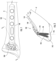
- an orthopedic implant 100 may be a bone plate for repairing fractures in a patient's bone or bone portions B. That is, as shown, the orthopedic implant 100 may be in the form of a bone plate 140 including one or more fasteners 190 for securing the implant (e.g., bone plate) 140 to the patient's bone B. As previously mentioned, the orthopedic implant 100 may be any now known or hereafter developed implant receiving a fastener for securing to a patient's bone or bone portions B. Similarly, the fastener 190 may be any now known or hereafter developed fastener. As shown, in one embodiment, the fastener 190 includes a head portion 194 and a shaft portion 192.
- the shaft portion 192 may be threaded or non-threaded.
- the head portion 194 of the fastener 190 includes at least one thread or the like.
- the head portion 194 may include a bore for receiving a driver in order to drive the fastener 190 through the plate 140 and into the patient's bone B.
- the bone plate 140 may include one or more openings 200 for receiving a head portion 194 of a fastener 190 inserted therein. That is, as will be appreciated by one of ordinary skill in the art, the bone plate 140 may include a lower or bone contacting surface 142, an upper surface 144 opposite the lower or bone contacting surface 142, and a plurality of openings 200 extending between the upper surface 144 and the lower or bone contacting surface 142 for receiving a plurality of fasteners 190, respectively, for coupling the bone plate 140 to the patient's bone or bone portions B. As will be described herein, one or more of the openings 200 include a plurality of fins for coupling with, engaging, etc.
- the head portion 194 of the fastener 190 inserted therein (referred to herein as a finned opening).
- the finned openings 200 can be positioned anywhere on the implant (e.g., bone plate) 100.
- the fastener 190 can be inserted into the finned opening 200 and fixed relative to the plate 140 at various insertion angles to capture random bone portions, fragments, etc. that have split from the bone during fracture and secure the bone portions, fragments, etc. to the plate 140.
- the finned openings 200 enable a fastener 190 inserted therein to achieve a greater range of insertion angles as compared to, for example, a conventional locking screw 90 that is threadably coupled to the bone plate 140.
- the angular position of the fastener 190 may be rotated through a range of approximately ⁇ 15 degrees, although the range of allowable polyaxial rotation can vary, including greater and less than the fifteen degrees.
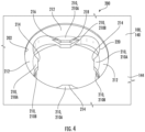
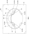
- the finned opening 200 formed in the bone plate 140 includes an inner surface 202 and a plurality of inwardly protruding fins 210 that extend toward a central axis 201 of the finned opening 200.
- Each fin 210 includes a base 212, a terminal end or tip 214, and side surfaces 216, 218.
- the bases 212 forming concave portions 220.
- the concave portions 220 are smooth and non-threaded, and as illustrated, the entire inner surface 202 of the finned opening 200 can be devoid of any threads.
- the bases 212 can extend from the inner surface 202 of the finned opening 200.
- the fins 210 are integrally connected to, and protruding from, the inner surface 202 of the finned opening 200.
- the finned opening 200 may include a radius between the inner surface 202 and the top of the fins 210 and each fin 210 may taper in thickness from its base 212 to its terminal end or tip 214.
- the finned opening 200 may be seen to have a jagged circumference formed by protruding fins 210.
- the protruding fins 210 may form a concave portion of the inner surface 202.
- the protruding fins 210 have bases 212 that meet the inner surface 202 along planes as described in greater detail below.
- the fins 210 can taper to form inwardly tapered side surfaces 216, 218.
- the side surfaces 216, 218 of the fins 210 may taper outwardly or may be parallel with each other.
- the terminal ends or tips 214 can have any shape suitable for engaging the head portion 194 of the fastener 190.
- the terminal ends or tips 214 can be rounded, pointed, square, rectangular, or any other appropriate configuration.
- the fins 210 may be trapezoidally-shaped, rounded, oval, square, rectangular, curved, rhomboid, diamond-shaped, triangular, or the like.
- the fins 210 may be provided as a series of concavely indented, inwardly protruding fins that are adapted to secure a head 194 of a fastener 190 in place at varying angles (e.g., fins 210 engage the threads or other surfaces formed on the head portion 194 of the fastener 190). Additional information on the configuration and nature of the fins can be found in U.S. Patent No. 8,105,367 .
- the finned openings 200 include a plurality of first or upper fins 210A and a plurality of second or lower fins 210B. That is, the finned openings 200 may include a first or upper row of fins including a plurality of first or upper fins 210A and a second or lower row of fins including a plurality of second or lower fins 210B, wherein the first or upper row of fins is spaced from the second or lower rows of fins. In use, the first or upper row of fins are positioned closer to a first or upper surface of the implant and the second or lower fins are positioned closer to the opposite or lower surface of the implant.
- the upper fins 210A may be stacked or aligned with the lower fins 210B. That is, in one embodiment, the upper fins 210A and the lower fins 210B are positioned circumferentially about the finned opening 200 in a vertically stacked position.
- the upper and lower rows of fins may each include four fins positioned ninety-degrees apart in a vertically stacked position. That is, in one embodiment, the upper row of fins and the lower row of fins may include four upper fins 210A oriented ninety-degrees apart around the finned opening 200 and four lower fins 210B oriented directly beneath the upper fins 210A.
- the upper and lower rows of fins may include more of less fins.
- the upper and lower rows of fins may each include three fins positioned 120 degrees apart in a vertically stacked position, six fins positioned 60 degrees apart in a vertically stacked position, etc.
- the upper and lower fins may be positioned offset, or partially offset, from each other. That is, the upper and lower fins may not be positioned in a vertically stacked relationship but rather the upper fins may be positioned offset, or partially offset, from the lower fins (e.g., the upper fins may be positioned in-between the lower fins).
- the upper row of fins and the lower row of fins may include different number of fins such as, for example, the upper row may include four fins and the lower row of fins may include five fins, or the like.
- one or more of the individual fins 210 residing within the upper and lower rows of fins may have different properties, configurations, etc. (used interchangeably herein without the intent to limit) from one or more of the other fins residing within the upper and lower rows of fins. That is, at least one of the fins 210 has a different configuration from at least one of the other remaining fins.
- the different configuration may correspond to a different length or relative inscribed diameter (used interchangeably) (e.g., measured from a base 212 of the fin 210 to a terminal end 214 of the fin 210), or a different thickness (e.g., a different cross-sectional diameter, thickness, etc.), or a combination thereof.
- a different length or relative inscribed diameter used interchangeably
- at least one of the fins may be said to have a first configuration and at least one of the fins may be said to have a second configuration.
- the second configuration is smaller, less material fins that will enhance/improve the construct.
- the first configuration may have a thickness at the terminal end 214 of the fin 210 of approximately 22.86 centimeters (0.009 inches).
- the second configuration may have a thickness at the terminal end 214 of the fin 210 of approximately 22.86 centimeters (0.009 inches) or less, although as will be appreciated by one of ordinary skill in the art these dimensions are just one example and the fins may have other dimensions.
- the second configuration may have a larger inscribed diameter as compared to the first configuration.
- each of the upper fins 210A and the lower fins 210B in the first and second rows may be arranged and configured in a vertically stacked relationship so that the lower fins 210B are aligned with, positioned beneath, etc. the upper fins 210A in a vertical stack.
- the upper fin 210A may have a different configuration as compared to the lower fin 210B in its vertical stack (e.g., positioned directly above it). That is, for example, the upper fin 210A in a vertical stack may have a first configuration and the lower fin 210B in the vertical stack may have the second configuration.
- the upper and lower fins 210A, 210B may extend into the opening toward the central axis 201 of the finned opening 200 by a different amount, extent, or the like.
- the shorter fins may have a different cross-sectional area (e.g., a different thickness) relative to the longer fins.
- each of the upper fins 210A and the lower fins 210B may alternate configurations as the fins 210 are circumferentially disposed in the finned opening 200.
- the finned opening 200 including four upper fins 210A and four lower fins 210B, although the number of fins may be varied, orientated in a vertically stacked relationship so that, for example, the upper and the lower fins may be said to reside at positions A, B, C and D, respectively, corresponding to, for example, 12 O'clock, 3 O'clock, 6 O'clock, and 9 O'clock
- the upper fin 210A at position A (e.g., 12 O'clock) and position C (e.g., 6 O'clock) may have a different configuration as compared to the lower fin 210B at position A (e.g., 12 O'clock) and position C (e.g., 6 O'clock) (e.g., the upper fins 210A may have
- the upper fins 210A located at position B (e.g., 3 O'clock) and position D (e.g., 9 O'clock) may have a different configuration as compared to the lower fins at position B (e.g., 3 O'clock) and position D (e.g., 9 O'clock) (e.g., the upper fins 210A may have the second configuration and the lower fins 210B may have the first configuration).
- the upper fin 210A at each clock position may have a different configuration from the lower fin 210B at the same clock position, with the upper and lower fins 210A, 210B alternating configurations as one traverses about the circumference of the finned opening 200. That is, as one moves about the circumference of the finned opening 200, the first fin at a first clock position may have a different length and/or different cross-section than the second fin at the first clock position.
- the second fin at a second clock position may have a different length and/or different cross-section than the first fin at the second clock position, and so on as one traverses about the circumference of the finned opening 200.
- the first fin at a first clock position may have a longer length than the second fin at the first clock position.
- the first fin at the first clock position may have a smaller cross-sectional area (e.g., reduced thickness) than the second fin at the first clock position.
- the second fin at a second clock position may have a longer length than the first fin at the second clock position.
- the second fin at the second clock position may have a smaller cross-sectional area (e.g., reduced thickness) than the first fin at the second clock position, and so on as one traverses about the circumference of the finned opening 200.
- insertion of a fastener 190 into a finned opening 200 results in the upper and lower fins 210A, 210B being threaded into the head portion 194 of the fastener 190.
- the fins 210 act to prevent backing out of the fastener 190 from the implant 100.
- the fastener 190 may be inserted into the finned opening 200 at a variety of angles, while still securing the fastener 190 to the implant 100.
- each individual fin 210 is typically dependent at least in part upon the pitch and threads on the head portion 194 of the fastener 190.
- a larger plate/implant 100 for use with a larger fastener 190 will likely be thicker and will have larger and thicker fins than a smaller plate/implant 100 (for example, for use on a smaller bone).
- the fins 210 are particularly thin so that they can be moved up or down and deform under pressure.
- the upper and lower fins 210A, 210B will either deform, deflect, or combinations thereof.
- the fins 210 may be pressed toward the edges of the finned opening 200.
- a non-limiting exemplary range of thicknesses for the fins 210 is from about 0.1 mm to about 5 mm, although larger and smaller sizes are possible.
- the fins 210 are intended to fit between threads or the like formed on the head portion 194 of the fastener 190.
- a ratio of a thread pitch formed on the head portion 194 of the fastener 190 to the distance or spacing between the upper and lower fins 210A, 210B is between 0.85 to 1.15.
- the finned openings 200 may include a countersink.
- the head portion 194 of the fastener 190 may interact with the countersink to facilitate improved polyaxial rotation of the fastener 190 relative to the implant 100.
- the bases 212 of the upper fins 210A all meet, for example, in substantially the same plane and then angle downwardly and inwardly at a similar angle or slope.
- the bases 212 of the lower fins 210B all meet, for example, in substantially the same plane and then angle downwardly and inwardly at a similar angle or slope.
- the downward angle of the upper and lower fins 210A, 210B may be the same, although it is envisioned that the upper fins 210A may be angled at a different angle than the lower fins 210B.
- one or both of the upper and lower planes may be parallel to a surface of the implant. Alternatively, one or both of the upper and lower planes may be non-parallel to a surface of the implant.
- the central axis 201 of the finned openings 200 may be perpendicular to the surface of the implant or the central axis 201 may be non-perpendicular to the implant.
- the finned openings 200 provide an improved stable connection between the fasteners 190 and the implant 100 that permits different angles to be obtained between the fasteners 190 and the implant 100, while securing the fastener 190 to the implant 100.
- This allows the surgeon greater versatility to reach denser areas of bone or capture random bone fragments that are in irregular positions, for example, in cases of severe fractures with highly fragmented bones.
- the fastener and implant system advantageously allows the surgeon to choose the angle at which the fastener 190 is inserted through, and rigidly affixed in, an opening of the implant 100.
- the plurality of fins 210 may engage the head portion 194 of the fastener 190 when the fastener 190 is inserted into the finned opening 200 such that the fastener 190 can be inserted and retained at any one of a plurality of angles relative to the finned opening 200 (e.g., the configuration of the fins act to improve the resistance to cantilever load on the fastener 190 when locked into the fins regardless of the direction or angle of screw relative to the implant 100).
- the fins 210 may deflect and/or deform so that the fins 210 are interposed between the threads or the like on the head 194 of the fastener 190.
- the fins 210 grasp, for example, the threads formed on the head 194 of the fastener 190 in order to secure the fastener 190 in place relative to the implant 100 at any desired insertion angle.
- the fins 210 can be very thin so that as the threads start to grab the fins 210, the fins 210 can move up or down as appropriate to engage the threads and secure the fastener 190 in the finned opening 200.
- the threads engage the fins 210 so that the fins 210 fit between the threads.
- the movement of fins 210 can be a permanent deformation, so that the fins 210 cannot flex back and allow the fastener 190 to work its way out.
- All directional references e.g., proximal, distal, upper, lower, upward, downward, left, right, lateral, longitudinal, front, back, top, bottom, above, below, vertical, horizontal, radial, axial, clockwise, and counterclockwise
- Connection references e.g., attached, coupled, connected, and joined
- connection references are to be construed broadly and may include intermediate members between a collection of elements and relative movement between elements unless otherwise indicated. As such, connection references do not necessarily infer that two elements are directly connected and in fixed relation to each other.
Landscapes
- Health & Medical Sciences (AREA)
- Orthopedic Medicine & Surgery (AREA)
- Life Sciences & Earth Sciences (AREA)
- Surgery (AREA)
- Neurology (AREA)
- Heart & Thoracic Surgery (AREA)
- Engineering & Computer Science (AREA)
- Biomedical Technology (AREA)
- Nuclear Medicine, Radiotherapy & Molecular Imaging (AREA)
- Medical Informatics (AREA)
- Molecular Biology (AREA)
- Animal Behavior & Ethology (AREA)
- General Health & Medical Sciences (AREA)
- Public Health (AREA)
- Veterinary Medicine (AREA)
- Surgical Instruments (AREA)
- Prostheses (AREA)
Claims (15)
- Orthopädisches Implantat (100), umfassend:eine Knochenkontaktfläche (142);eine obere Oberfläche (144) gegenüber der Knochenkontaktfläche (142); undmehrere Öffnungen (200), die sich zwischen der Knochenkontaktfläche (142) und der oberen Fläche (144) erstrecken, wobei jede der mehreren Öffnungen (200) angeordnet und dazu ausgelegt ist, bei Gebrauch ein Befestigungselement (190) zum Koppeln des orthopädischen Implantats (100) mit dem Knochen eines Patienten aufzunehmen;wobei:mindestens eine der mehreren Öffnungen (200) eine erste und eine zweite Reihe von Rippen (210A, 210B) beinhaltet;jede der ersten und zweiten Reihen von Rippen (210A, 210B) mehrere Rippen (210) beinhaltet, die umlaufend um die mindestens eine Öffnung (200) angeordnet sind, wobei die mehreren Rippen (210) angeordnet und dazu ausgelegt sind, in einen Kopfabschnitt (194) eines jeweiligen darin eingesetzten Befestigungselements (190) einzugreifen, wobei jede Rippe (210) Folgendes umfasst: eine Basis (212), ein Anschlussende (214) und Seitenflächen (216, 218), die sich von der Basis (212) zum Anschlussende (214) hin verjüngen, wobei die Basis (212) einen konkaven Abschnitt (220) zwischen angrenzenden Anschlussenden (214) bildet; undmindestens eine der mehreren Rippen (210) in der ersten und der zweiten Reihe von Rippen (210A, 210B) eine andere Auslegung als mindestens eine einer anderen der mehreren Rippen (210) in der ersten und der zweiten Reihe von Rippen (210A, 210B) aufweist.
- Orthopädisches Implantat nach Anspruch 1, wobei jede der mehreren Rippen (210) in der ersten Reihe von Rippen (210A) in einer vertikal gestapelten Beziehung mit einer der mehreren Rippen (210) in der zweiten Reihe von Rippen (210B) angeordnet und ausgelegt ist, so dass die zweite Reihe von Rippen (210B) umlaufend mit der ersten Reihe von Rippen (210A) ausgerichtet ist.
- Orthopädisches Implantat nach Anspruch 2, wobei für jeden der vertikalen Stapel von ersten und zweiten Reihen von Rippen (210A, 210B) die Rippe (210) in der ersten Reihe von Rippen (210A) eine andere Auslegung im Vergleich zu der Rippe (210) in der zweiten Reihe von Rippen (210B) in ihrem jeweiligen vertikalen Stapel aufweist.
- Orthopädisches Implantat (100) nach Anspruch 3, wobei jede Rippe in der ersten und der zweiten Reihe von Finnen (210A, 210B) eine alternierende Auslegung von Rippen beinhaltet, wenn die Rippen umlaufend in der mindestens einen Öffnung (200) angeordnet sind.
- Orthopädisches Implantat (100) nach Anspruch 3, wobei jede der ersten und zweiten Reihen von Rippen (210A, 210B) vier Rippen beinhaltet, die neunzig Grad zueinander ausgerichtet sind, so dass die vier Rippen in der ersten und zweiten Reihe von Rippen (210A, 210B) in den Umfangspositionen A, B, C und D positioniert sind; wobei:die Rippe in der ersten Reihe von Rippen (210A) an den Positionen A und C eine erste Auslegung umfasst;die Rippe in der ersten Reihe von Rippen (210A) an den Positionen B und D eine zweite Auslegung umfasst;die Rippe in der zweiten Reihe von Rippen (210B) an den Positionen A und C die zweite Auslegung umfasst; unddie Rippe in der zweiten Reihe von Rippen (210B) an den Positionen B und D die erste Auslegung umfasst.
- Orthopädisches Implantat (100) nach Anspruch 3, wobei bei Bewegung um einen Umfang der mindestens einen Öffnung (200) jede Rippe in der ersten Reihe von Rippen (210A) eine andere Auslegung im Vergleich zu jeder Rippe in der zweiten Reihe von Rippen (210B) in ihrem jeweiligen vertikalen Stapel aufweist, wobei jede Rippe in der ersten Reihe von Rippen (210A) und jede Rippe in der zweiten Reihe von Rippen (210B) alternierende Auslegungen aufweisen.
- Orthopädisches Implantat (100) nach Anspruch 3, wobei die unterschiedliche Auslegung von Rippen aus einer unterschiedlichen Länge, einer unterschiedlichen Dicke oder einer Kombination davon ausgewählt wird.
- Orthopädisches Implantat (100) nach Anspruch 2, wobei sich mindestens eine der Rippen in der ersten Reihe von Rippen (210A) in der vertikal gestapelten Beziehung weiter in die mindestens eine Öffnung (200) als die Rippe in der zweiten Reihe von Rippen (210B) erstreckt.
- Orthopädisches Implantat (100) nach Anspruch 8, wobei mindestens eine der Rippen in der ersten Reihe von Rippen (210A) eine dünnere Querschnittsfläche an einer Spitze davon im Vergleich zu der Rippe in der zweiten Reihe von Rippen (210B) in der vertikal gestapelten Beziehung aufweist.
- Orthopädisches Implantat (100) nach Anspruch 1, wobei das orthopädische Implantat (100) eine Knochenplatte (140) ist.
- Knochenplatte (140), die Folgendes umfasst:eine Knochenkontaktfläche (142); eine obere Oberfläche (144) gegenüber der Knochenkontaktfläche (142); undmindestens eine Öffnung (200), die sich zwischen der Knochenkontaktfläche (142) und der oberen Oberfläche (144) erstreckt; wobei die mindestens eine Öffnung (200) eine erste und eine zweite Reihe von Rippen (210A, 210B) beinhaltet, wobei jede der ersten und der zweiten Reihe von Rippen (210A, 210B) mehrere Rippen (210) beinhaltet, die umlaufend um die mindestens eine Öffnung (200) herum angeordnet sind;wobei jede Rippe (210) Folgendes umfasst: eine Basis (212), ein Anschlussende (214) und Seitenflächen (216, 218), die sich von der Basis (212) zum Anschlussende (214) hin verjüngen, wobei die Basis (212) einen konkaven Abschnitt (220) zwischen angrenzenden Anschlussenden (214) bildet; undwobei die Rippen (210) in der ersten Reihe von Rippen (210A) in einer vertikal gestapelten Beziehung mit den Rippen in der zweiten Reihe von Rippen (210B) ausgerichtet sind;wobei für jede vertikal gestapelte Beziehung die Rippe in der ersten Reihe von Rippen (210A) eine aus einer ersten Auslegung und einer zweiten Auslegung aufweist, wobei die Rippe in der zweiten Reihe von Rippen (210B) die andere aus der ersten Auslegung und der zweiten Auslegung aufweist, wobei sich die erste Auslegung von der zweiten Auslegung unterscheidet.
- Knochenplatte (140) nach Anspruch 11, wobei die erste Auslegung eine andere Länge aufweist, wie von einer Basis der Rippe zu einer Spitze der Rippe gemessen, wobei die zweite Auslegung eine dünnere Querschnittsfläche an der Spitze der Rippe ist.
- Knochenplatte (140) nach Anspruch 11, wobei die Rippen in der ersten Reihe von Rippen (210A) bei Bewegung um einen Umfang der mindestens einen Öffnung (200) zwischen erster und zweiter Auslegung alternieren; und wobei die Rippen in der zweiten Reihe von Rippen (210B) bei Bewegung um einen Umfang der mindestens einen Öffnung (200) zwischen erster und zweiter Auslegung alternieren.
- Knochenplatte (140) nach Anspruch 11, wobei die erste Auslegung eine andere Länge ist, wie von einer Basis der Rippe zu einer Spitze der Rippe gemessen, wobei die Rippen in der ersten und zweiten Reihe von Rippen (210A, 210B) bei Bewegung um einen Umfang der mindestens einen Öffnung (200) zwischen erster und zweiter Auslegung alternieren, so dass eine Rippe mit längerer Länge bei Bewegung um einen Umfang der mindestens einen Öffnung (200) zwischen der ersten und der zweiten Reihe von Rippen (210A, 210B) alterniert.
- Knochenplatte (140) nach Anspruch 11, wobei jede der ersten und zweiten Reihen von Rippen (210A, 210B) vier Rippen beinhaltet, die neunzig Grad zueinander ausgerichtet sind, so dass die vier Rippen in der ersten und zweiten Reihe von Rippen (210A, 210B) in den Umfangspositionen A, B, C und D positioniert sind; wobei:die Rippe in der ersten Reihe von Rippen (210A) an den Positionen A und C die erste Auslegung umfasst;die Rippe in der ersten Reihe von Rippen (210A) an den Positionen B und D die zweite Auslegung umfasst;die Rippe in der zweiten Reihe von Rippen (210B) an den Positionen A und C die zweite Auslegung umfasst; unddie Rippe in der zweiten Reihe von Rippen (210B) an den Positionen B und D die erste Auslegung umfasst.
Applications Claiming Priority (2)
| Application Number | Priority Date | Filing Date | Title |
|---|---|---|---|
| US201962858727P | 2019-06-07 | 2019-06-07 | |
| PCT/US2020/035729 WO2020247381A1 (en) | 2019-06-07 | 2020-06-02 | Orthopedic implant with improved variable angle locking mechanism |
Publications (2)
| Publication Number | Publication Date |
|---|---|
| EP3979934A1 EP3979934A1 (de) | 2022-04-13 |
| EP3979934B1 true EP3979934B1 (de) | 2025-04-30 |
Family
ID=71842769
Family Applications (1)
| Application Number | Title | Priority Date | Filing Date |
|---|---|---|---|
| EP20747187.1A Active EP3979934B1 (de) | 2019-06-07 | 2020-06-02 | Orthopädisches implantat mit verbessertem verriegelungsmechanismus mit veränderlichem winkel |
Country Status (5)
| Country | Link |
|---|---|
| US (2) | US12070253B2 (de) |
| EP (1) | EP3979934B1 (de) |
| CN (1) | CN113924054B (de) |
| AU (1) | AU2020287867A1 (de) |
| WO (1) | WO2020247381A1 (de) |
Families Citing this family (6)
| Publication number | Priority date | Publication date | Assignee | Title |
|---|---|---|---|---|
| US12402922B2 (en) * | 2020-04-29 | 2025-09-02 | Smith & Nephew, Inc. | Bone plate with length adjusting elongate hole, and corresponding methods of use |
| WO2021236495A1 (en) | 2020-05-19 | 2021-11-25 | Smith & Nephew, Inc. | Periprosthetic bone plate |
| US11849983B2 (en) * | 2020-08-18 | 2023-12-26 | Field Orthopaedics Pty Ltd | Bone fixation system and method |
| IT202000031901A1 (it) * | 2020-12-22 | 2022-06-22 | Ge Me S General Medical Supplies S R L | Sistema di accoppiamento poliassiale a contatto plurimo |
| US20240382241A1 (en) | 2021-09-16 | 2024-11-21 | Smith & Nephew, Inc. | Variable fixation bone plates |
| US20250177150A1 (en) | 2022-03-27 | 2025-06-05 | Smith & Nephew, Inc. | Orthopedic implant assembly for proximal femur replacement |
Family Cites Families (39)
| Publication number | Priority date | Publication date | Assignee | Title |
|---|---|---|---|---|
| US7303564B2 (en) | 2002-02-01 | 2007-12-04 | Spinal Concepts, Inc. | Spinal plate extender system and method |
| US6955677B2 (en) * | 2002-10-15 | 2005-10-18 | The University Of North Carolina At Chapel Hill | Multi-angular fastening apparatus and method for surgical bone screw/plate systems |
| DE20321151U1 (de) | 2003-08-26 | 2006-09-07 | Synthes Gmbh | Knochenplatte |
| US8105367B2 (en) | 2003-09-29 | 2012-01-31 | Smith & Nephew, Inc. | Bone plate and bone plate assemblies including polyaxial fasteners |
| US8574268B2 (en) * | 2004-01-26 | 2013-11-05 | DePuy Synthes Product, LLC | Highly-versatile variable-angle bone plate system |
| US7637928B2 (en) * | 2004-01-26 | 2009-12-29 | Synthes Usa, Llc | Variable angle locked bone fixation system |
| DE102005015496B4 (de) | 2005-03-31 | 2012-11-15 | Intercus Gmbh | Osteosyntheseimplantat mit nicht ineinandergreifenden Durchführungen zur Aufnahme von Knochenschrauben |
| US7766948B1 (en) * | 2005-05-05 | 2010-08-03 | Ebi, Llc | Bone fixation assembly |
| DE102005042766B4 (de) | 2005-07-13 | 2009-08-20 | Königsee Implantate und Instrumente zur Osteosynthese GmbH | Plattenloch einer Knochenplatte für die Osteosynthese |
| AU2006272646C1 (en) * | 2005-07-25 | 2018-06-21 | Smith & Nephew, Inc. | Systems and methods for using polyaxial plates |
| US8382807B2 (en) | 2005-07-25 | 2013-02-26 | Smith & Nephew, Inc. | Systems and methods for using polyaxial plates |
| FR2890848B1 (fr) * | 2005-09-19 | 2007-11-23 | Dlp Soc Responsabilite Limitee | Dispositif d'osteosynthese. |
| AU2006306120B2 (en) * | 2005-10-25 | 2012-11-15 | Anthem Orthopaedics Llc | Bone fastening assembly and bushing and screw for use therewith |
| US20080015592A1 (en) * | 2006-06-28 | 2008-01-17 | Depuy Products, Inc. | CAM/compression lock plate |
| US20080234749A1 (en) * | 2007-01-26 | 2008-09-25 | Zimmer Technology, Inc. | Bone plate providing threaded locking head screw capture |
| US8870931B2 (en) * | 2007-03-21 | 2014-10-28 | The University Of North Carolina At Chapel Hill | Anti-unscrewing and multi-angular fastening apparatuses and methods for surgical bone screw/plate systems |
| US7963982B2 (en) * | 2007-07-16 | 2011-06-21 | X-Spine Systems, Inc. | Implant plate screw locking system and screw having a locking member |
| BRPI0818869A2 (pt) * | 2008-07-29 | 2015-05-05 | Synthes Gmbh | Placa para fixação em uma parte alvo de osso a ser tratada, e, método. |
| DE102008043370A1 (de) * | 2008-10-31 | 2010-05-06 | Universität Rostock | Fixationsvorrichtung für Knochen |
| US8834536B2 (en) * | 2009-07-16 | 2014-09-16 | Nexxt Spine, LLC | Cervical plate fixation system |
| KR101885507B1 (ko) * | 2010-06-02 | 2018-08-07 | 신세스 게엠바하 | 뼈 플레이트 |
| CN103025256B (zh) | 2010-07-21 | 2016-07-20 | 斯恩蒂斯有限公司 | 用于骨缝合术的装置 |
| JP2014522673A (ja) * | 2011-06-15 | 2014-09-08 | スミス アンド ネフュー インコーポレーテッド | 角度が可変とされたロッキング用のインプラント |
| DE202011106835U1 (de) * | 2011-10-14 | 2012-02-06 | Königsee Implantate GmbH | Knochenplatte |
| US8940029B2 (en) * | 2011-10-17 | 2015-01-27 | Biomet Trauma, LLC | Variable locking bone plating system |
| CA2858559C (en) * | 2011-12-07 | 2021-04-20 | Smith & Nephew, Inc. | Orthopedic implant augments |
| US9387022B2 (en) * | 2012-06-27 | 2016-07-12 | DePuy Synthes Products, Inc. | Variable angle bone fixation device |
| US9433454B2 (en) * | 2013-03-14 | 2016-09-06 | Amei Technologies, Inc. | Variable angle screws, plates and systems |
| US10231766B2 (en) * | 2013-12-23 | 2019-03-19 | Smith & Nephew, Inc. | Distal radius plate |
| EP2932929B1 (de) * | 2014-04-15 | 2017-02-08 | Biedermann Technologies GmbH & Co. KG | Schraubelement zur Verwendung in der spinalen, orthopädischen oder traumatologischen Chirurgie und System mit solch einem Schraubelement und daran angepassten Schraubendreher |
| US10258395B2 (en) * | 2014-09-25 | 2019-04-16 | Stryker European Holdings I, Llc | Bone plate locking mechanism |
| US9987062B2 (en) * | 2015-03-24 | 2018-06-05 | Advanced Orthopaedic Solutions, Inc. | Variable angle bone plate |
| WO2017048909A1 (en) * | 2015-09-18 | 2017-03-23 | Smith & Nephew, Inc. | Bone plate |
| US10624686B2 (en) * | 2016-09-08 | 2020-04-21 | DePuy Synthes Products, Inc. | Variable angel bone plate |
| US10772665B2 (en) * | 2018-03-29 | 2020-09-15 | DePuy Synthes Products, Inc. | Locking structures for affixing bone anchors to a bone plate, and related systems and methods |
| US11013541B2 (en) * | 2018-04-30 | 2021-05-25 | DePuy Synthes Products, Inc. | Threaded locking structures for affixing bone anchors to a bone plate, and related systems and methods |
| US10925651B2 (en) * | 2018-12-21 | 2021-02-23 | DePuy Synthes Products, Inc. | Implant having locking holes with collection cavity for shavings |
| HRP20190451A2 (hr) * | 2019-03-06 | 2020-09-18 | Janoš Kodvanj | Vijak s varijabilnim kutom zaključavanja i korespondirajući sustav zaključavanja |
| US11179180B2 (en) * | 2019-06-11 | 2021-11-23 | DePuy Synthes Products, Inc. | Deformable threaded locking structures, and related systems and methods |
-
2020
- 2020-06-02 EP EP20747187.1A patent/EP3979934B1/de active Active
- 2020-06-02 AU AU2020287867A patent/AU2020287867A1/en active Pending
- 2020-06-02 WO PCT/US2020/035729 patent/WO2020247381A1/en not_active Ceased
- 2020-06-02 US US17/616,785 patent/US12070253B2/en active Active
- 2020-06-02 CN CN202080041996.4A patent/CN113924054B/zh active Active
-
2024
- 2024-08-05 US US18/794,085 patent/US20240390044A1/en active Pending
Also Published As
| Publication number | Publication date |
|---|---|
| US12070253B2 (en) | 2024-08-27 |
| EP3979934A1 (de) | 2022-04-13 |
| US20240390044A1 (en) | 2024-11-28 |
| WO2020247381A1 (en) | 2020-12-10 |
| CN113924054B (zh) | 2025-03-18 |
| CN113924054A (zh) | 2022-01-11 |
| AU2020287867A1 (en) | 2021-12-09 |
| US20220233222A1 (en) | 2022-07-28 |
Similar Documents
| Publication | Publication Date | Title |
|---|---|---|
| EP3979934B1 (de) | Orthopädisches implantat mit verbessertem verriegelungsmechanismus mit veränderlichem winkel | |
| US12390253B2 (en) | Variable angle locking implant | |
| AU2006272646B2 (en) | Systems and methods for using polyaxial plates | |
| US8105367B2 (en) | Bone plate and bone plate assemblies including polyaxial fasteners | |
| AU2013202741B2 (en) | Systems and methods for using polyaxial plates | |
| WO2025259470A1 (en) | Orthopedic intramedullary nail and bone plate system | |
| AU2016200490B2 (en) | Systems and methods for using polyaxial plates |
Legal Events
| Date | Code | Title | Description |
|---|---|---|---|
| STAA | Information on the status of an ep patent application or granted ep patent |
Free format text: STATUS: UNKNOWN |
|
| STAA | Information on the status of an ep patent application or granted ep patent |
Free format text: STATUS: THE INTERNATIONAL PUBLICATION HAS BEEN MADE |
|
| PUAI | Public reference made under article 153(3) epc to a published international application that has entered the european phase |
Free format text: ORIGINAL CODE: 0009012 |
|
| STAA | Information on the status of an ep patent application or granted ep patent |
Free format text: STATUS: REQUEST FOR EXAMINATION WAS MADE |
|
| 17P | Request for examination filed |
Effective date: 20220104 |
|
| AK | Designated contracting states |
Kind code of ref document: A1 Designated state(s): AL AT BE BG CH CY CZ DE DK EE ES FI FR GB GR HR HU IE IS IT LI LT LU LV MC MK MT NL NO PL PT RO RS SE SI SK SM TR |
|
| DAV | Request for validation of the european patent (deleted) | ||
| DAX | Request for extension of the european patent (deleted) | ||
| GRAP | Despatch of communication of intention to grant a patent |
Free format text: ORIGINAL CODE: EPIDOSNIGR1 |
|
| STAA | Information on the status of an ep patent application or granted ep patent |
Free format text: STATUS: GRANT OF PATENT IS INTENDED |
|
| INTG | Intention to grant announced |
Effective date: 20241128 |
|
| RAP3 | Party data changed (applicant data changed or rights of an application transferred) |
Owner name: SMITH & NEPHEW ASIA PACIFIC PTE. LIMITED Owner name: SMITH & NEPHEW ORTHOPAEDICS AG Owner name: SMITH & NEPHEW, INC. |
|
| P01 | Opt-out of the competence of the unified patent court (upc) registered |
Free format text: CASE NUMBER: APP_63412/2024 Effective date: 20241203 |
|
| GRAS | Grant fee paid |
Free format text: ORIGINAL CODE: EPIDOSNIGR3 |
|
| GRAA | (expected) grant |
Free format text: ORIGINAL CODE: 0009210 |
|
| STAA | Information on the status of an ep patent application or granted ep patent |
Free format text: STATUS: THE PATENT HAS BEEN GRANTED |
|
| AK | Designated contracting states |
Kind code of ref document: B1 Designated state(s): AL AT BE BG CH CY CZ DE DK EE ES FI FR GB GR HR HU IE IS IT LI LT LU LV MC MK MT NL NO PL PT RO RS SE SI SK SM TR |
|
| REG | Reference to a national code |
Ref country code: CH Ref legal event code: EP Ref country code: GB Ref legal event code: FG4D |
|
| REG | Reference to a national code |
Ref country code: IE Ref legal event code: FG4D |
|
| REG | Reference to a national code |
Ref country code: DE Ref legal event code: R096 Ref document number: 602020050416 Country of ref document: DE |
|
| PGFP | Annual fee paid to national office [announced via postgrant information from national office to epo] |
Ref country code: DE Payment date: 20250408 Year of fee payment: 6 |
|
| PGFP | Annual fee paid to national office [announced via postgrant information from national office to epo] |
Ref country code: GB Payment date: 20250430 Year of fee payment: 6 |
|
| PGFP | Annual fee paid to national office [announced via postgrant information from national office to epo] |
Ref country code: FR Payment date: 20250409 Year of fee payment: 6 |
|
| REG | Reference to a national code |
Ref country code: NL Ref legal event code: MP Effective date: 20250430 |
|
| REG | Reference to a national code |
Ref country code: AT Ref legal event code: MK05 Ref document number: 1789312 Country of ref document: AT Kind code of ref document: T Effective date: 20250430 |
|
| PG25 | Lapsed in a contracting state [announced via postgrant information from national office to epo] |
Ref country code: FI Free format text: LAPSE BECAUSE OF FAILURE TO SUBMIT A TRANSLATION OF THE DESCRIPTION OR TO PAY THE FEE WITHIN THE PRESCRIBED TIME-LIMIT Effective date: 20250430 Ref country code: ES Free format text: LAPSE BECAUSE OF FAILURE TO SUBMIT A TRANSLATION OF THE DESCRIPTION OR TO PAY THE FEE WITHIN THE PRESCRIBED TIME-LIMIT Effective date: 20250430 Ref country code: PT Free format text: LAPSE BECAUSE OF FAILURE TO SUBMIT A TRANSLATION OF THE DESCRIPTION OR TO PAY THE FEE WITHIN THE PRESCRIBED TIME-LIMIT Effective date: 20250901 |
|
| REG | Reference to a national code |
Ref country code: LT Ref legal event code: MG9D |
|
| PG25 | Lapsed in a contracting state [announced via postgrant information from national office to epo] |
Ref country code: NO Free format text: LAPSE BECAUSE OF FAILURE TO SUBMIT A TRANSLATION OF THE DESCRIPTION OR TO PAY THE FEE WITHIN THE PRESCRIBED TIME-LIMIT Effective date: 20250730 Ref country code: GR Free format text: LAPSE BECAUSE OF FAILURE TO SUBMIT A TRANSLATION OF THE DESCRIPTION OR TO PAY THE FEE WITHIN THE PRESCRIBED TIME-LIMIT Effective date: 20250731 |
|
| PG25 | Lapsed in a contracting state [announced via postgrant information from national office to epo] |
Ref country code: NL Free format text: LAPSE BECAUSE OF FAILURE TO SUBMIT A TRANSLATION OF THE DESCRIPTION OR TO PAY THE FEE WITHIN THE PRESCRIBED TIME-LIMIT Effective date: 20250430 Ref country code: PL Free format text: LAPSE BECAUSE OF FAILURE TO SUBMIT A TRANSLATION OF THE DESCRIPTION OR TO PAY THE FEE WITHIN THE PRESCRIBED TIME-LIMIT Effective date: 20250430 |
|
| PG25 | Lapsed in a contracting state [announced via postgrant information from national office to epo] |
Ref country code: BG Free format text: LAPSE BECAUSE OF FAILURE TO SUBMIT A TRANSLATION OF THE DESCRIPTION OR TO PAY THE FEE WITHIN THE PRESCRIBED TIME-LIMIT Effective date: 20250430 |
|
| PG25 | Lapsed in a contracting state [announced via postgrant information from national office to epo] |
Ref country code: HR Free format text: LAPSE BECAUSE OF FAILURE TO SUBMIT A TRANSLATION OF THE DESCRIPTION OR TO PAY THE FEE WITHIN THE PRESCRIBED TIME-LIMIT Effective date: 20250430 |
|
| PG25 | Lapsed in a contracting state [announced via postgrant information from national office to epo] |
Ref country code: AT Free format text: LAPSE BECAUSE OF FAILURE TO SUBMIT A TRANSLATION OF THE DESCRIPTION OR TO PAY THE FEE WITHIN THE PRESCRIBED TIME-LIMIT Effective date: 20250430 |
|
| PG25 | Lapsed in a contracting state [announced via postgrant information from national office to epo] |
Ref country code: RS Free format text: LAPSE BECAUSE OF FAILURE TO SUBMIT A TRANSLATION OF THE DESCRIPTION OR TO PAY THE FEE WITHIN THE PRESCRIBED TIME-LIMIT Effective date: 20250731 |
|
| PG25 | Lapsed in a contracting state [announced via postgrant information from national office to epo] |
Ref country code: IS Free format text: LAPSE BECAUSE OF FAILURE TO SUBMIT A TRANSLATION OF THE DESCRIPTION OR TO PAY THE FEE WITHIN THE PRESCRIBED TIME-LIMIT Effective date: 20250830 |
|
| PG25 | Lapsed in a contracting state [announced via postgrant information from national office to epo] |
Ref country code: LV Free format text: LAPSE BECAUSE OF FAILURE TO SUBMIT A TRANSLATION OF THE DESCRIPTION OR TO PAY THE FEE WITHIN THE PRESCRIBED TIME-LIMIT Effective date: 20250430 |
|
| PG25 | Lapsed in a contracting state [announced via postgrant information from national office to epo] |
Ref country code: SM Free format text: LAPSE BECAUSE OF FAILURE TO SUBMIT A TRANSLATION OF THE DESCRIPTION OR TO PAY THE FEE WITHIN THE PRESCRIBED TIME-LIMIT Effective date: 20250430 Ref country code: DK Free format text: LAPSE BECAUSE OF FAILURE TO SUBMIT A TRANSLATION OF THE DESCRIPTION OR TO PAY THE FEE WITHIN THE PRESCRIBED TIME-LIMIT Effective date: 20250430 |
|
| PG25 | Lapsed in a contracting state [announced via postgrant information from national office to epo] |
Ref country code: CZ Free format text: LAPSE BECAUSE OF FAILURE TO SUBMIT A TRANSLATION OF THE DESCRIPTION OR TO PAY THE FEE WITHIN THE PRESCRIBED TIME-LIMIT Effective date: 20250430 |
|
| PG25 | Lapsed in a contracting state [announced via postgrant information from national office to epo] |
Ref country code: EE Free format text: LAPSE BECAUSE OF FAILURE TO SUBMIT A TRANSLATION OF THE DESCRIPTION OR TO PAY THE FEE WITHIN THE PRESCRIBED TIME-LIMIT Effective date: 20250430 |
|
| PG25 | Lapsed in a contracting state [announced via postgrant information from national office to epo] |
Ref country code: SK Free format text: LAPSE BECAUSE OF FAILURE TO SUBMIT A TRANSLATION OF THE DESCRIPTION OR TO PAY THE FEE WITHIN THE PRESCRIBED TIME-LIMIT Effective date: 20250430 Ref country code: RO Free format text: LAPSE BECAUSE OF FAILURE TO SUBMIT A TRANSLATION OF THE DESCRIPTION OR TO PAY THE FEE WITHIN THE PRESCRIBED TIME-LIMIT Effective date: 20250430 |
|
| REG | Reference to a national code |
Ref country code: CH Ref legal event code: H13 Free format text: ST27 STATUS EVENT CODE: U-0-0-H10-H13 (AS PROVIDED BY THE NATIONAL OFFICE) Effective date: 20260127 |
|
| PG25 | Lapsed in a contracting state [announced via postgrant information from national office to epo] |
Ref country code: IT Free format text: LAPSE BECAUSE OF FAILURE TO SUBMIT A TRANSLATION OF THE DESCRIPTION OR TO PAY THE FEE WITHIN THE PRESCRIBED TIME-LIMIT Effective date: 20250430 |
|
| PG25 | Lapsed in a contracting state [announced via postgrant information from national office to epo] |
Ref country code: MC Free format text: LAPSE BECAUSE OF FAILURE TO SUBMIT A TRANSLATION OF THE DESCRIPTION OR TO PAY THE FEE WITHIN THE PRESCRIBED TIME-LIMIT Effective date: 20250430 |