EP3979667B1 - Hörgerät mit einer rückkopplungsdetektionseinheit - Google Patents
Hörgerät mit einer rückkopplungsdetektionseinheit Download PDFInfo
- Publication number
- EP3979667B1 EP3979667B1 EP21204386.3A EP21204386A EP3979667B1 EP 3979667 B1 EP3979667 B1 EP 3979667B1 EP 21204386 A EP21204386 A EP 21204386A EP 3979667 B1 EP3979667 B1 EP 3979667B1
- Authority
- EP
- European Patent Office
- Prior art keywords
- loop
- feedback
- phase
- magnitude
- signal
- Prior art date
- Legal status (The legal status is an assumption and is not a legal conclusion. Google has not performed a legal analysis and makes no representation as to the accuracy of the status listed.)
- Active
Links
Images


Classifications
-
- H—ELECTRICITY
- H04—ELECTRIC COMMUNICATION TECHNIQUE
- H04R—LOUDSPEAKERS, MICROPHONES, GRAMOPHONE PICK-UPS OR LIKE ACOUSTIC ELECTROMECHANICAL TRANSDUCERS; DEAF-AID SETS; PUBLIC ADDRESS SYSTEMS
- H04R25/00—Deaf-aid sets, i.e. electro-acoustic or electro-mechanical hearing aids; Electric tinnitus maskers providing an auditory perception
- H04R25/50—Customised settings for obtaining desired overall acoustical characteristics
- H04R25/505—Customised settings for obtaining desired overall acoustical characteristics using digital signal processing
-
- H—ELECTRICITY
- H04—ELECTRIC COMMUNICATION TECHNIQUE
- H04M—TELEPHONIC COMMUNICATION
- H04M9/00—Arrangements for interconnection not involving centralised switching
- H04M9/08—Two-way loud-speaking telephone systems with means for conditioning the signal, e.g. for suppressing echoes for one or both directions of traffic
- H04M9/082—Two-way loud-speaking telephone systems with means for conditioning the signal, e.g. for suppressing echoes for one or both directions of traffic using echo cancellers
-
- H—ELECTRICITY
- H04—ELECTRIC COMMUNICATION TECHNIQUE
- H04R—LOUDSPEAKERS, MICROPHONES, GRAMOPHONE PICK-UPS OR LIKE ACOUSTIC ELECTROMECHANICAL TRANSDUCERS; DEAF-AID SETS; PUBLIC ADDRESS SYSTEMS
- H04R25/00—Deaf-aid sets, i.e. electro-acoustic or electro-mechanical hearing aids; Electric tinnitus maskers providing an auditory perception
- H04R25/45—Prevention of acoustic reaction, i.e. acoustic oscillatory feedback
- H04R25/453—Prevention of acoustic reaction, i.e. acoustic oscillatory feedback electronically
-
- H—ELECTRICITY
- H04—ELECTRIC COMMUNICATION TECHNIQUE
- H04R—LOUDSPEAKERS, MICROPHONES, GRAMOPHONE PICK-UPS OR LIKE ACOUSTIC ELECTROMECHANICAL TRANSDUCERS; DEAF-AID SETS; PUBLIC ADDRESS SYSTEMS
- H04R3/00—Circuits for transducers, loudspeakers or microphones
-
- H—ELECTRICITY
- H04—ELECTRIC COMMUNICATION TECHNIQUE
- H04R—LOUDSPEAKERS, MICROPHONES, GRAMOPHONE PICK-UPS OR LIKE ACOUSTIC ELECTROMECHANICAL TRANSDUCERS; DEAF-AID SETS; PUBLIC ADDRESS SYSTEMS
- H04R2225/00—Details of deaf aids covered by H04R25/00, not provided for in any of its subgroups
- H04R2225/43—Signal processing in hearing aids to enhance the speech intelligibility
-
- H—ELECTRICITY
- H04—ELECTRIC COMMUNICATION TECHNIQUE
- H04R—LOUDSPEAKERS, MICROPHONES, GRAMOPHONE PICK-UPS OR LIKE ACOUSTIC ELECTROMECHANICAL TRANSDUCERS; DEAF-AID SETS; PUBLIC ADDRESS SYSTEMS
- H04R2420/00—Details of connection covered by H04R, not provided for in its groups
- H04R2420/01—Input selection or mixing for amplifiers or loudspeakers
-
- H—ELECTRICITY
- H04—ELECTRIC COMMUNICATION TECHNIQUE
- H04R—LOUDSPEAKERS, MICROPHONES, GRAMOPHONE PICK-UPS OR LIKE ACOUSTIC ELECTROMECHANICAL TRANSDUCERS; DEAF-AID SETS; PUBLIC ADDRESS SYSTEMS
- H04R2430/00—Signal processing covered by H04R, not provided for in its groups
- H04R2430/03—Synergistic effects of band splitting and sub-band processing
-
- H—ELECTRICITY
- H04—ELECTRIC COMMUNICATION TECHNIQUE
- H04R—LOUDSPEAKERS, MICROPHONES, GRAMOPHONE PICK-UPS OR LIKE ACOUSTIC ELECTROMECHANICAL TRANSDUCERS; DEAF-AID SETS; PUBLIC ADDRESS SYSTEMS
- H04R3/00—Circuits for transducers, loudspeakers or microphones
- H04R3/02—Circuits for transducers, loudspeakers or microphones for preventing acoustic reaction, i.e. acoustic oscillatory feedback
Definitions
- the present disclosure relates to hearing devices, e.g. hearing aids, in particular to feedback detection and control in hearing devices.
- a feedback control system is used to minimize the negative effects from the acoustic feedback problem.
- a feedback detector is often used to determine critical feedback situations, and it provides this information to the feedback control system to control its behaviour, to ensure the best possible feedback performance.
- US20040252853A1 deals with detection and suppression of oscillations due to feedback.
- the method involves converting the signal into frequency bands in the frequency domain, applying, for a selected period of time, a randomly changing phase to the signal in at least one of said frequency bands, and reconverting the converted signal into an output waveform signal.
- the selected period is divided into a series of successive time windows, and for each successive time window a newly generated random or pseudo-random phase is applied to the signal.
- the method can be used in combination with a method for detecting oscillation in said signal in each of the frequency bands, a randomly changing phase applied in each frequency band for which said oscillation has been detected.
- a hearing aid circuit for reducing feedback.
- a hearing aid circuit includes a correlation detector that detects correlation at a feedforward path input and that provides a correlation output to a phase shifter.
- the phase shifter introduces a phase shift along a feedforward path.
- a phase measurement circuit measures a phase shift at a feedforward path in-put, and provides a phase measurement output to an internal feedback processor.
- the internal feedback processor adjusts internal feedback as a function of the phase measurement to suppress coupling of external audio feedback along the feedforward path.
- the present disclosure presents a method of detecting critical feedback situations by estimating the open loop magnitude function and the open loop phase function.
- a hearing device :
- Acoustic feedback is taken to mean feedback that propagates as sound (in air) from an output transducer to an input transducer of the hearing device.
- Electrical feedback may e.g. be in the form of noise induced in conductors (cross-talk) or picked up from the coil of the loudspeaker.
- Mechanical feedback is taken to mean feedback that propagates as mechanical vibration of a housing or other physical parts of the hearing device from an output transducer to an input transducer as vibration.
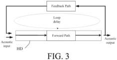
- a (feedback) loop is defined as an external (e.g. acoustic) path, where loop delay D is taken to mean the time required for a signal to travel through the loop consisting of the forward path of the hearing device and the feedback path from output transducer to input unit of the hearing device from an output transducer to an input unit and an internal (e.g. electric, processing) path from the input unit to the output transducer.
- the (feedback) loop defines (or exhibits) a loop delay D.
- the loop consists of said forward path and the acoustic feedback path, the loop exhibiting a loop delay D a .
- the loop consists of said forward path and the mechanical feedback path, the loop exhibiting a loop delay D m .
- the loop consists of said forward path and the electric feedback path, the loop exhibiting a loop delay De.
- the term ⁇ repeatedly determining' is taken to include determining the parameters in question at points in time ... m'-2D, m'-D, m', or at points in time ..., m'-zD, m', where z is a positive integer, and m' is a specific time instant of the hearing device.
- the term ⁇ repeatedly determining' may include every previous successive time instant..., m-2, m-1, m, but may alternatively e.g. be taken mean every second (i.e. at ... m-4, m-2, m) or every fourth (i.e. at ... m-8, m-4, m), or every D th time instance (i.e. at ... m-2D, m-D, m).
- the term 'to provide feedback detection signal, FbDet(k,m), indicative of feedback or a risk of feedback' is in the present context taken to include to provide feedback detection signal, FbDet(k,m) that indicates whether or not a level of feedback in frequency band k at time unit m is larger than or smaller than a threshold value (a binary indication).
- the first and/or second threshold levels are frequency band specific (i.e. may dependent on frequency band index k). In an embodiment, the first and/or second threshold levels can be time dependent (i.e. may depend on time index m).
- the hearing device comprises an analysis filter bank for converting said electric input signal IN to a number of frequency sub-band electric input signals IN(k,m), where k and m are frequency sub-band and time indices, respectively.
- the filter bank is used to divide a time domain input signal into time-frequency domain (frequency sub-band) signals. For each time-frequency domain signal, feedback detection is separately determined.
- the feedback detection is done in the time-domain rather than time-frequency domain.
- the frequency and sub-band and time indices (k,m) are not used, and instead the full-band time index (n) applies.
- a band-limited signal (or signal(s)) is(are) used for feedback detection.
- band index l and the time index m i.e. (l,m)
- band index l and the time index m can e.g. be used (where one index l' may cover one or more corresponding indices k (e.g. k', k'+1, k'+2).
- the feedback loop delay D is in the present context taken to mean the time required for a signal to travel through the loop consisting of the (electric) forward path of the hearing device and the (acoustic) feedback path from output transducer to input unit of the haring device (as illustrated in FIG. 3 ).
- the feedback loop delay D is assumed to be known, e.g. measured or estimated in advance of the use of the hearing device, and e.g.
- the hearing device is configured to (adaptively) measure or estimate the loop delay during use (e.g. automatically, e.g. during power-on, or initiated by a user via a user interface, or continuously, e.g. according to a predetermined scheme or when certain criteria are fulfilled).
- the loop delay D used for calculating LpMag, LpPhase, LpMagDiff and LpPhaseDiff is a frequency dependent value of loop delay D(k), where k is the frequency sub-band index.
- the delay d' of the acoustic feedback path from the output to the input of the hearing device is frequency dependent.
- the delay of the hearing device itself, i.e. the processing delay d of the (electric) forward path of the hearing device from input to output is frequency dependent.
- the processing delay varies with frequency.
- the processing delay increases with frequency (e.g. when the forward path comprises IIR filters).
- a group delay of the acoustic feedback path is frequency dependent.
- N is a number of loop delays
- m N ⁇ D is the time instant N feedback loop delay D earlier
- MagThresh is a loop magnitude threshold value.
- Example values of N are 0, 1, 2,...
- the magnitude threshold value MagThresh is equal to -3 dB, or -2 dB, or -1 dB, or 0 dB, or +1 dB, or +2 dB, or +3 dB.
- the magnitude feedback detection signal LpMagDet is a binary signal (0 or 1).
- the loop phase threshold value PhaseThresh is smaller than or equal to 0.5, 0.4, 0.3, 0.2, 0.1, 0.05, or 0.01... (radians).
- the phase feedback detection signal LpPhaseDet is a binary signal (0 or 1).
- the feedback detection signal FbDet is e.g. a binary signal (0 or 1).
- the expression and ( crit1,crit2 ) is taken to mean that for the expression to be true criterion 1 ( crit1 ) as well as criterion 2 ( crit2 ) have to be fulfilled.
- the loop magnitude threshold value MagThresh is equal to -1.5 dB
- the loop phase difference threshold value PhaseDiffThresh is equal to 0.3 (cf. e.g. FIG. 4B ).
- the feedback detection unit further comprises a loop transfer function estimation and correction unit receiving as inputs the signals loop magnitude LpMag and loop phase LpPhase, and provides as an output the complex signal LtfEst representing an estimate of the complex loop transfer function.
- the complex signal LtfEst comprises magnitude (LpMagEst) and phase (LpPhaseEst) of the estimated loop transfer function.
- the complex signal LtfEst is an output signal of the feedback detection unit.
- the loop transfer function estimation and correction unit is configured to receive an input related to a correction of the loop transfer function, e.g. due to actions initiated in response to a change of the feedback detection signal FbDet.
- the hearing device e.g. a hearing aid, further comprises an action information unit configured to take as inputs the feedback detection signal FbDet and the loop transfer function estimate LtfEst from the feedback detection unit and to provide as an output an action information signal ACINF.
- the action information unit ACT is configured to receive information about the current (estimate) of the loop transfer function (LtfEst) AND the current feedback detection (FbDet, 0 or 1). Based on this information the action information unit ACT decides on appropriate actions (reduction of gain, increase adaptation rate of the feedback estimation, the application of frequency shift in the forward path, frequency transposition, notch filtering, half-wave rectification, etc.) and initiates such actions.
- the action information signal ACINF is fed to the loop transfer function estimation and correction unit and is configured to correct the loop transfer function.
- such correction may be due to an action initiated in response to a change of the feedback detection signal FbDet.
- such action may relate to the change of a parameter of a feedback cancellation system, to a modification of a frequency shift applied to a signal of the forward path, to a modification of the applied forward gain of the forward path, etc.
- the action information unit ACT comprises an input control signal CTRL configured to activate actions that may influence the feedback detection.
- the action information unit ACT is configured to receive control signals related to activation of one or more of the following: magnitude/phase changes, application of probe noise, changing adaptation speed, etc.
- the action information unit ACT is configured to test actions activated via the control signal of the action information unit ACT.
- the feedback detection unit can be used to test the effect of different actions, e.g. actions intended to reduce feedback, such actions being e.g. activated via the control signal of the action information unit ACT.
- the test may e.g. comprise the following steps: A) the initial feedback is estimated with the feedback detection unit (UFFE), B) the CTRL signal to the action information unit ACT imposes an action to modify feedback (e.g., Gain reduction, phase modification, frequency transposition, compression, half-wave rectification, notch filtering, etc.), C) the feedback detection is re-estimated. These two subsequent measurements are then used to determine feedback (and the influence of the applied action).
- UTF feedback detection unit
- FbDet equals to '1' (corresponding to feedback detection) if any (i.e. one or more) of the different feedback detection signals FbDet(D j ) detects feedback.
- the criterion is that resulting feedback detection signal FbDet is equal to ⁇ 1', if more than one of the different feedback detection signals FbDet(D j ) detect feedback.
- the hearing device comprises a listening device, e.g. a hearing aid, e.g. a hearing instrument, e.g. a hearing instrument adapted for being located at the ear or fully or partially in the ear canal of a user, e.g. a headset, an earphone, an ear protection device or a combination thereof.
- the hearing device comprises a hearing aid, a headset, an earphone, an ear protection device or a combination thereof.
- the hearing device is or constitutes a hearing aid.
- the signal processing unit is configured for enhancing the input signals and providing a processed output signal.
- the hearing device e.g. the signal processing unit
- the hearing device is adapted to provide a frequency dependent gain and/or a level dependent compression and/or a transposition (with or without frequency compression) of one or more frequency ranges to one or more other frequency ranges, e.g. to compensate for a hearing impairment of a user.
- a frequency dependent gain and/or a level dependent compression and/or a transposition with or without frequency compression
- the hearing device comprises an output transducer adapted for providing a stimulus perceived by the user as an acoustic signal based on a processed electric signal.
- the output transducer comprises a receiver (loudspeaker) for providing the stimulus as an acoustic signal to the user.
- the output transducer comprises a vibrator for providing the stimulus as mechanical vibration of a skull bone to the user (e.g. in a bone-attached or bone-anchored hearing device).
- the term ⁇ stimuli perceivable as sound to a user' is taken to include acoustic stimuli (sound, e.g. from a loudspeaker), electric stimuli (e.g. from an electrode array of a cochlear implant for stimulating the cochlear nerve) and mechanical stimuli (e.g. from a vibrator of a bone conducting hearing aid).
- the hearing device comprises an input transducer for providing an electric input signal representing sound.
- the hearing device comprises a directional microphone system adapted to enhance a target acoustic source among a multitude of acoustic sources in the local environment of the user wearing the hearing device.
- the directional system is adapted to detect (such as adaptively detect) from which direction a particular part of the microphone signal originates. This can be achieved in various different ways as e.g. described in the prior art.
- the hearing device comprises antenna and transceiver circuitry for wirelessly receiving a direct electric input signal from another device, e.g. a communication device or another hearing device.
- the hearing device is (or comprises) a portable device, e.g. a device comprising a local energy source, e.g. a battery, e.g. a rechargeable battery.
- a portable device e.g. a device comprising a local energy source, e.g. a battery, e.g. a rechargeable battery.
- the hearing device comprises a forward or signal path between an input transducer (microphone system and/or direct electric input (e.g. a wireless receiver)) and an output transducer.
- the signal processing unit is located in the forward path.
- the hearing device comprises an analysis path comprising functional components for analyzing the input signal (e.g. determining a level, a modulation, a type of signal, an acoustic feedback estimate, etc.).
- some or all signal processing of the analysis path and/or the signal path is conducted in the frequency domain.
- some or all signal processing of the analysis path and/or the signal path is conducted in the time domain.
- An analogue electric signal representing an acoustic signal is converted to a digital audio signal in an analogue-to-digital (AD) conversion process, where the analogue signal is sampled with a predefined sampling frequency or rate f s , f s being e.g. in the range from 8 kHz to 40 kHz (adapted to the particular needs of the application) to provide digital samples x n (or x[n]) at discrete points in time t n (or n), each audio sample representing the value of the acoustic signal at t n by a predefined number N s of bits, N s being e.g. in the range from 1 to 48 bit, e.g. 24 bits.
- N s being e.g. in the range from 1 to 48 bit, e.g. 24 bits.
- a number of audio samples are arranged in a time frame.
- a time frame comprises 64 audio data samples. Other frame lengths may be used depending on the practical application.
- the hearing devices comprise an analogue-to-digital (AD) converter to digitize an analogue input with a predefined sampling rate, e.g. 20 kHz.
- the hearing devices comprise a digital-to-analogue (DA) converter to convert a digital signal to an analogue output signal, e.g. for being presented to a user via an output transducer.
- AD analogue-to-digital
- DA digital-to-analogue
- the hearing device e.g. the microphone unit, and or the transceiver unit comprise(s) a TF-conversion unit for providing a time-frequency representation of an input signal.
- the time-frequency representation comprises an array or map of corresponding complex or real values of the signal in question in a particular time and frequency range.
- the TF conversion unit comprises a filter bank for filtering a (time varying) input signal and providing a number of (time varying) output (sub-band) signals each comprising a distinct frequency range of the input signal.
- the TF conversion unit comprises a Fourier transformation unit (e.g.
- the frequency range considered by the hearing device from a minimum frequency f min to a maximum frequency f max comprises a part of the typical human audible frequency range from 20 Hz to 20 kHz, e.g. a part of the range from 20 Hz to 12 kHz.
- a signal of the forward and/or analysis path of the hearing device is split into a number NI of frequency bands, where NI is e.g. larger than 5, such as larger than 10, such as larger than 50, such as larger than 100, such as larger than 500, at least some of which are processed individually.
- this action can potentially affect the feedback detection itself.
- this action modifies the loop phase, and hence this information should be taken into account when detecting the phase feedback.
- the action information is used as part of the feedback detection, e.g., as a "gain-reduction-test” or "phase-change-test” method.
- a gain reduction or a phase change of a certain amount is applied in the forward path upon feedback detection.
- a reduction of loop magnitude or a phase change by the same amount should be observed. This can be used as a confirmation of feedback detection.
- the action information signal can be used to improve the feedback detection (e.g. its confidence or validity).
- the actual use of the action information signal in order to improve the feedback detection signal depends on the action.
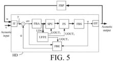
- FIG. 5 shows a simplified block diagram of an embodiment of a hearing device comprising a feedback detector according to the present disclosure when used to control various processing parts of the hearing device.
- the embodiment of hearing device of FIG. 5 is similar to the embodiment of FIG. 1 .
- a processing part of the forward path around the signal processing unit SPU is carried out in frequency sub-bands.
- the forward path hence comprises a filter bank (analysis filter bank FBA before the signal processing unit SPU and synthesis filter bank FBS before the output transducer OT).
- the forward path further comprises a configurable decorrelation unit FS in the forward path, e.g. in the form of a frequency shift ⁇ f (e.g. ⁇ f ⁇ 10 Hz).
- the feedback detector is configured to provide individual control signals UOUT 1 , UOUT 2 , and UOUT 3 to the signal processing unit SPU, to the frequency shifting unit FS and to the feedback estimation unit FBE, respectively.
- FIG. 6 shows a hearing system comprising a hearing device and an auxiliary device in communication with each other.
- FIG. 6 shows an embodiment of a hearing aid according to the present disclosure comprising a BTE-part located behind an ear or a user and an ITE part located in an ear canal of the user.
- FIG. 6 illustrates an exemplary hearing aid ( HD ) formed as a receiver in the ear (RITE) type hearing aid comprising a BTE-part ( BTE ) adapted for being located behind pinna and a part ( ITE ) comprising an output transducer (e.g. a loudspeaker/receiver, SPK) adapted for being located in an ear canal ( Ear canal ) of the user (e.g. exemplifying a hearing aid (HD) as shown in FIG. 1 or 5 ).
- the BTE-part ( BTE ) and the ITE-part ( ITE ) are connected (e.g. electrically connected) by a connecting element ( IC ).
- IC connecting element
- the BTE part ( BTE ) comprises two input transducers (here microphones) ( IT 1 , IT 2 ) each for providing an electric input audio signal representative of an input sound signal ( S BTE ) from the environment.
- the input sound signal S BTE includes a contribution from sound source S.
- the hearing aid of FIG. 6 further comprises two wireless receivers ( WLR 1 , WLR 2 ) for providing respective directly received auxiliary audio and/or information signals.
- the hearing aid ( HD ) further comprises a substrate ( SUB ) whereon a number of electronic components are mounted, functionally partitioned according to the application in question (analogue, digital, passive components, etc.), but including a configurable signal processing unit ( SPU ), a beam former filtering unit ( BFU ), and a memory unit ( MEM ) coupled to each other and to input and output transducers via electrical conductors Wx.
- the mentioned functional units (as well as other components) may be partitioned in circuits and components according to the application in question (e.g. with a view to size, power consumption, analogue vs. digital processing, etc.), e.g.
- the configurable signal processing unit ( SPU ) provides an enhanced audio signal, which is intended to be presented to a user.
- the ITE part ( ITE ) comprises an output unit in the form of a loudspeaker (receiver) ( SPK ) for converting the electric signal ( OUT ) to an acoustic signal (providing, or contributing to, acoustic signal S ED at the ear drum ( Ear drum ) .
- the ITE-part further comprises an input unit comprising an input transducer (e.g. a microphone) ( IT 3 ) for providing an electric input audio signal representative of an input sound signal S ITE from the environment (including from sound source S) at or in the ear canal.
- the hearing aid may comprise only the BTE-microphones ( IT 1 , IT 2 ) .
- the hearing aid may comprise only the ITE-microphone ( IT 3 ).
- the hearing aid may comprise an input unit ( IT 4 ) located elsewhere than at the ear canal in combination with one or more input units located in the BTE-part and/or the ITE-part.
- the ITE-part further comprises a guiding element, e.g. a dome, ( DO ) for guiding and positioning the ITE-part in the ear canal of the user.
- the hearing aid ( HD ) exemplified in FIG. 6 is a portable device and further comprises a battery ( BAT ) for energizing electronic components of the BTE- and ITE-parts.
- the hearing aid ( HD ) may e.g. comprise a directional microphone system (beam former filtering unit ( BFU )) adapted to spatially filter a target acoustic source among a multitude of acoustic sources in the local environment of the user wearing the hearing aid device.
- the directional system is adapted to detect (such as adaptively detect) from which direction a particular part of the microphone signal (e.g. a target part and/or a noise part) originates.
- the beam former filtering unit is adapted to receive inputs from a user interface (e.g. a remote control or a smartphone) regarding the present target direction.
- the memory unit ( MEM ) may e.g.
- W ij frequency dependent constants
- the hearing aid of FIG. 6 may constitute or form part of a hearing aid and/or a binaural hearing aid system according to the present disclosure.
- the hearing aid comprises a feedback detection unit as described above.
- the processing of an audio signal in a forward path of the hearing aid may e.g. be performed fully or partially in the time-frequency domain.
- the processing of signals in an analysis or control path of the hearing aid may be fully or partially performed in the time-frequency domain.
- the hearing aid (HD) may comprise a user interface UI, e.g. as shown in FIG. 6 implemented in an auxiliary device (AUX), e.g. a remote control, e.g. implemented as an APP in a smartphone or other portable (or stationary) electronic device.
- auxiliary device e.g. a remote control
- the screen of the user interface illustrates a Feedback Detection APP, with the subtitle 'Configure feedback detection. Display current feedback' (upper part of the screen). Criteria for detecting feedback can be configured by the user via the APP (middle part of screen denoted 'Select feedback criteria').
- the feedback criteria can be selected between a number of criteria, here between ⁇ Loop Magnitude', ⁇ Loop Phase' and ⁇ Loop Phase Difference'.
- the user has selected a loop magnitude threshold value of 0 dB, and a loop phase threshold value of 0.1 (rad).
- the current feedback situation determined using the selected criteria is displayed (lower part of screen, denoted ⁇ Detected feedback [0,1,]').
- a value between 0 and 1 is used to indicate a degree of severity of the current feedback (overall, although determined on a frequency sub-band level).
- the legend is indicated as OK ( ) for values below 0.5 and as critical ( ) for values above 0.8.
- the current value of (relative) feedback is illustrated by a number (here 0.5) at a corresponding location on the horizontal grey bar (to a value between a minimum value (Min corresponding to 0) and a maximum value (Max corresponding to 1) with a medium value (Med corresponding to 0.5) there between).
- the APP is configured to provide an (possibly graphic) illustration of the current feedback detection (e.g. signal FbDet(k,m)) on a frequency sub-band level, e.g. relative to a current feedback margin.
- the current feedback detection e.g. signal FbDet(k,m)
- the auxiliary device and the hearing aid are adapted to allow communication of data representative of the currently selected direction (if deviating from a predetermined direction (already stored in the hearing aid)) to the hearing aid via a, e.g. wireless, communication link (cf. dashed arrow WL2 in FIG. 6 ).
- the communication link WL2 may e.g. be based on far field communication, e.g. Bluetooth or Bluetooth Low Energy (or similar technology), implemented by appropriate antenna and transceiver circuitry in the hearing aid (HD) and the auxiliary device (AUX), indicated by transceiver unit WLR 2 in the hearing aid.
- FIG. 7 shows a block diagram of a second embodiment of a feedback detector according to the present disclosure in a sound processing environment.
- This embodiment may be of special value in situations, where the delay (d') of the acoustic feedback path is significant compared to the delay (d) of the electric forward path of the hearing device, so that the assumption that d' ⁇ d (cf. FIG. 3 ) is no longer valid or valid to a smaller degree.
- Such situation may e.g. occur when a (acoustically) reflecting surface is (brought) in the vicinity of the user, e.g. less than 1 m from an ear of the user.
- a parallel estimate of the feedback situation for different assumed values of loop delay D j is of value.
- the feedback detection unit is configured to assign values of loop delay from a minimum value (D 1 ) to a maximum value (D ND ) according to a predefined or adaptive scheme, where D 1 ⁇ D 2 ... ⁇ D ND .
- a predefined or adaptively determined criterion e.g. a logic, e.g. Boolean, criterion
- the criterion is that resulting feedback detection signal FbDet is equal to ⁇ 1', if more than one of the different feedback detection signals FbDet(D j ) detect feedback.
- the feedback detector has access to a measured or estimated (current) value of loop delay and is configured to give particular weight to (e.g. to select) the value(s) of the feedback detection signal (and possibly the estimate of the complex loop transfer function) provided by the processing part FBD j for which D; comes closest to the measured or estimated value D est of loop delay.
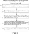
- FIG. 8 shows a flow diagram for a method of detecting feedback in a hearing device not falling under the scope of the appended claims.
- the hearing device comprises a forward path for processing an electric signal representing sound.
- the forward path comprises
- the method comprises
- connection or “coupled” as used herein may include wirelessly connected or coupled.
- the term “and/or” includes any and all combinations of one or more of the associated listed items. The steps of any disclosed method is not limited to the exact order stated herein, unless expressly stated otherwise.
Landscapes
- Engineering & Computer Science (AREA)
- Signal Processing (AREA)
- Physics & Mathematics (AREA)
- Acoustics & Sound (AREA)
- Health & Medical Sciences (AREA)
- General Health & Medical Sciences (AREA)
- Neurosurgery (AREA)
- Otolaryngology (AREA)
- Circuit For Audible Band Transducer (AREA)
- Measurement Of The Respiration, Hearing Ability, Form, And Blood Characteristics Of Living Organisms (AREA)
Claims (14)
- Hörgerät (HD), umfassend einen Vorwärtspfad zum Verarbeiten eines elektrischen Eingabesignals (IN), das Schall darstellt, wobei der Vorwärtspfad Folgendes umfasst:• eine Eingabeeinheit (IT) zum Empfangen oder Bereitstellen des elektrischen Eingabesignals (IN), das Schall darstellt,• eine Analysefilterbank (FBA) zum Umwandeln des elektrischen Eingabesignals (IN) in eine Anzahl von elektrischen Eingabesignalen auf dem Frequenzteilband IN(k,m), wobei k und m jeweils Frequenzteilband-bzw. Zeitindizes sind;• eine Signalverarbeitungseinheit (SPU) zum Anlegen einer frequenz- und/oder pegelabhängigen Verstärkung an ein Eingabesignal des Vorwärtspfades und Bereitstellen eines verarbeiteten Ausgabesignals (u) und• einen Ausgabewandler (OT) zum Erzeugen von Reizen, die für einen Benutzer auf Grundlage des verarbeiteten Ausgabesignals (u) als Schall wahrnehmbar sind;wobei das Hörgerät (HD) ferner Folgendes umfasst:• eine Rückkopplungsdetektionseinheit (UFFE), die dazu konfiguriert ist, über einen akustischen oder mechanischen oder elektrischen Rückkopplungspfad von dem Ausgabewandler (OT) zu der Eingabeeinheit (IT) eine Rückkopplung zu detektieren oder ein Risiko einer Rückkopplung zu bewerten,eine Schleife, die aus dem Vorwärtspfad und dem Rückkopplungspfad besteht, die definiert sind, wobei die Schleife eine Schleifenverzögerung D aufweist,wobei die Rückkopplungsdetektionseinheit Folgendes umfasst:• eine Betrags- und Phasenanalyseeinheit (M&P ANA) zum wiederholten Bestimmen von Größe (Mag) und Phase (Phase) des elektrischen Eingabesignals (IN) oder einer verarbeiteten Version davon (UIN) und die ferner dazu konfiguriert ist, Werte von Schleifengröße (LpMag), Schleifenphase (LpPhase) bzw. Schleifenphasendifferenzsignalen (LpPhaseDiff) auf Grundlage davon zu bestimmen; undeine Rückkopplungszustands- und -detektionseinheit (FB C&D), die dazu konfiguriert ist, Kriterien auf Größen- bzw. Phasenrückkopplungsbedingung auf Grundlage der Werte der Schleifengröße (LpMag) bzw. der Schleifenphasendifferenzsignale (LpPhaseDiff) zu prüfen und ein Rückkopplungsdetektionssignal, FbDet, bereitzustellen, das eine Rückkopplung oder ein Risiko einer Rückkopplung angibt; DADURCH GEKENNZEICHNET, DASS die Werte der Schleifengröße (LpMag), der Schleifenphase (LpPhase) und der Schleifenphasendifferenzsignale (LpPhaseDiff) in Abhängigkeit von der Schleifenverzögerung D bestimmt werden und wobei die Schleifenphasendifferenz die Differenz zwischen Werten der Parameterschleifenphase zu einem gegebenen Zeitpunkt, m, und einem Zeitpunkt, mD, eine Rückkopplungsschleifenverzögerung D früher ist, wobei die Größen- und Phasenanalyseeinheit (M&P ANA) dazu konfiguriert ist, die Schleifenphase LpPhase (in Bogenmaß) zu Zeitpunkt m als
 zu bestimmen, wobei wrap(.) den Phasenumwicklungsoperator bezeichnet, wobei die Schleifenphase somit einen möglichen Wertebereich von [-π, π] aufweist und wobei Phase (k,m) und Phase (k,mD) der Phasenwert des elektrischen Eingabesignals IN(k,m) zu Zeitpunkt m bzw. zu einer Rückkopplungsschleifenverzögerung D früher sind.
 - Hörgerät (HD) nach Anspruch 1, wobei die Größen- und Phasenanalyseeinheit (M&P ANA) dazu konfiguriert ist, die Schleifengröße zu Zeitpunkt m als

- Hörgerät (HD) nach Anspruch 1 oder 2, wobei die Größen- und Phasenanalyseeinheit (M&P ANA) dazu konfiguriert ist, die Schleifenphasendifferenz LpPhaseDiff(k,m) zu Zeitpunkt m als

- Hörgerät (HD) nach einem der Ansprüche 2 oder 3, wobei das Kriterium für den Schleifengrößenrückkopplungszustand wie folgt definiert ist:

- Hörgerät (HD) nach Anspruch 4, wobei ein Kriterium für die Rückkopplungsdetektion auf Grundlage einer Kombination von Kriterien für Schleifengröße (LpMag) und Rückkopplungsbedingungen für Schleifenphasendifferenz (LpPhaseDiff)


- Hörgerät (HD) nach Anspruch 5, wobei der Schleifengrößenschwellenwert MagThresh gleich -1,5 dB ist und der die Schleifenphasendifferenzschwellenwert PhaseDiffThresh gleich 0,3 ist.
- Hörgerät (HD) nach einem der Ansprüche 1-6, wobei die Rückkopplungsdetektionseinheit (UFFE) ferner eine Schleifenübertragungsfunktionsschätzungs- und -korrektureinheit (EST&C) umfasst, die die Signale von Schleifengröße LpMag und Schleifenphase LpPhase als Eingaben empfängt, das komplexe Signal LtfEst, das eine Schätzung der komplexen Schleifenübertragungsfunktion darstellt, als eine Ausgabe bereitstellt.
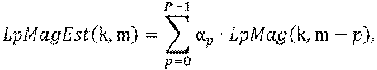
- Hörgerät (HD) nach einem der Ansprüche 2-7, wobei die Schleifengrößenschätzung LpMagEst(k,m) als die lineare Kombination einer Anzahl P von neuesten Werten der Schleifengröße LpMag(k,m) berechnet wird,
- Hörgerät (HD) nach Anspruch 7 oder 8, ferner umfassend eine Aktionsinformationseinheit (ACT), die dazu konfiguriert ist, das Rückkopplungsdetektionssignal FbDet und die Schleifenübertragungsfunktionsschätzung LtfEst von der Rückkopplungsdetektionseinheit (UFFE) als Eingaben zu nehmen und ein Aktionsinformationssignal ACINF als eine Ausgabe bereitzustellen.
- Hörgerät (HD) nach Anspruch 9, wobei die Aktionsinformationseinheit (ACT) ein Eingabesteuersignal CTRL umfasst, das dazu konfiguriert ist, Aktionen zu aktivieren, die die Rückkopplungsdetektion beeinflussen können.
- Hörgerät (HD) nach einem der Ansprüche 1-10, wobei die Rückkopplungsdetektionseinheit (UFFE) unterschiedliche Parallelverarbeitungseinheiten (FBD1, ..., FBDND) zum Bereitstellen eines Rückkopplungsdetektionssignals FbDet(Dj) umfasst, wobei jede dazu konfiguriert ist, eine unterschiedliche Schleifenverzögerung Dj, j=1, 2, ..., ND, zu verwenden, wobei ND die Anzahl unterschiedlicher Parallelverarbeitungseinheiten ist, und wobei die Rückkopplungsdetektionseinheit (UFFE) dazu konfiguriert ist, ein Kriterium auf die Rückkopplungsdetektionssignale FbDet(Dj), j=1, 2,..., ND, anzuwenden, um ein resultierendes Rückkopplungsdetektionssignal FbDet bereitzustellen.
- Hörgerät (HD) nach einem der Ansprüche 1-11, wobei das Hörgerät eine Hörhilfe ist oder umfasst.
- Verfahren zum Detektieren von Rückkopplung in einem Hörgerät (HD), wobei das Hörgerät Folgendes umfasst:einen Vorwärtspfad zum Verarbeiten eines elektrischen Eingabesignals (IN), das Schall darstellt, wobei der Vorwärtspfad Folgendes umfasst:• eine Eingabeeinheit (IT) zum Empfangen oder Bereitstellen des elektrischen Eingabesignals (IN), das Schall darstellt,• eine Analysefilterbank (FBA) zum Umwandeln des elektrischen Eingabesignals (IN) in eine Anzahl von elektrischen Eingabesignalen auf dem Frequenzteilband IN(k,m), wobei k und m jeweils Frequenzteilband-bzw. Zeitindizes sind;• eine Signalverarbeitungseinheit (SPU) zum Anlegen einer frequenz- und/oder pegelabhängigen Verstärkung an ein Eingabesignal des Vorwärtspfades und Bereitstellen eines verarbeiteten Ausgabesignals (u) und• einen Ausgabewandler (OT) zum Erzeugen von Reizen, die für einen Benutzer auf Grundlage des verarbeiteten Ausgabesignals (u) als Schall wahrnehmbar sind,wobei das Verfahren Folgendes umfasst:• Detektieren einer Rückkopplung oder Bewerten eines Risikos einer Rückkopplung über einen akustischen oder mechanischen oder elektrischen Rückkopplungspfad von dem Ausgabewandler zu der Eingabeeinheit, wobei eine Schleife, die aus dem Vorwärtspfad und dem akustischen oder mechanischen oder elektrischen Rückkopplungspfad besteht, definiert ist, wobei die Schleife eine Schleifenverzögerung D aufweist; durch∘ wiederholtes Bestimmen von Größe (Mag) und Phase (Phase) des elektrischen Eingabesignals (IN) oder einer verarbeiteten Version davon; und∘ Bestimmen von Werten von Schleifengröße (LpMag), Schleifenphase (LpPhase) bzw. Schleifenphasendifferenzsignalen (LpPhaseDiff) auf Grundlage davon;∘ Prüfen von Kriterien für Größen- bzw. Phasenrückkopplungszustand auf Grundlage der Werte der Schleifengröße (LpMag) bzw. der Schleifenphasendifferenzsignale (LpPhaseDiff) und∘ Bereitstellen eines Rückkopplungsdetektionssignals, FbDet, das eine Rückkopplung oder ein Risiko einer Rückkopplung angibt; DADURCH GEKENNZEICHNET, DASSdie Werte der Schleifengröße (LpMag), der Schleifenphase (LpPhase) und der Schleifenphasendifferenzsignale (LpPhaseDiff) in Abhängigkeit von der Schleifenverzögerung D bestimmt werden und wobei die Schleifenphasendifferenz die Differenz zwischen Werten der Parameterschleifenphase zu einem gegebenen Zeitpunkt, m, und einem Zeitpunkt, mD, eine Rückkopplungsschleifenverzögerung D früher ist, wobei die Größen- und Phasenanalyseeinheit (M&P ANA) dazu konfiguriert ist, die Schleifenphase LpPhase (in Bogenmaß) zu Zeitpunkt m als
 zu bestimmen, wobei wrap(.) den Phasenumwicklungsoperator bezeichnet, wobei die Schleifenphase somit einen möglichen Wertebereich von [-π, π] aufweist und wobei Phase(k,m) und Phase(k,mD) der Phasenwert des elektrischen Eingabesignals IN(k,m) zu Zeitpunkt m bzw. zu einer Rückkopplungsschleifenverzögerung D früher sind.
 - Datenverarbeitungssystem, umfassend einen Prozessor und Programmcodemittel zum Veranlassen des Prozessors, die Schritte des Verfahrens nach Anspruch 13 durchzuführen.
Applications Claiming Priority (2)
| Application Number | Priority Date | Filing Date | Title |
|---|---|---|---|
| EP16186338 | 2016-08-30 | ||
| EP17187337.5A EP3291581B1 (de) | 2016-08-30 | 2017-08-22 | Hörgerät mit einer rückkopplungserkennungseinheit |
Related Parent Applications (3)
| Application Number | Title | Priority Date | Filing Date |
|---|---|---|---|
| EPPCT/EP2017/187337 Previously-Filed-Application | 2017-08-22 | ||
| EP17187337.5A Division EP3291581B1 (de) | 2016-08-30 | 2017-08-22 | Hörgerät mit einer rückkopplungserkennungseinheit |
| EP17187337.5A Division-Into EP3291581B1 (de) | 2016-08-30 | 2017-08-22 | Hörgerät mit einer rückkopplungserkennungseinheit |
Publications (4)
| Publication Number | Publication Date |
|---|---|
| EP3979667A2 EP3979667A2 (de) | 2022-04-06 |
| EP3979667A3 EP3979667A3 (de) | 2022-07-06 |
| EP3979667C0 EP3979667C0 (de) | 2024-12-04 |
| EP3979667B1 true EP3979667B1 (de) | 2024-12-04 |
Family
ID=56842761
Family Applications (2)
| Application Number | Title | Priority Date | Filing Date |
|---|---|---|---|
| EP21204386.3A Active EP3979667B1 (de) | 2016-08-30 | 2017-08-22 | Hörgerät mit einer rückkopplungsdetektionseinheit |
| EP17187337.5A Active EP3291581B1 (de) | 2016-08-30 | 2017-08-22 | Hörgerät mit einer rückkopplungserkennungseinheit |
Family Applications After (1)
| Application Number | Title | Priority Date | Filing Date |
|---|---|---|---|
| EP17187337.5A Active EP3291581B1 (de) | 2016-08-30 | 2017-08-22 | Hörgerät mit einer rückkopplungserkennungseinheit |
Country Status (4)
| Country | Link |
|---|---|
| US (2) | US10368175B2 (de) |
| EP (2) | EP3979667B1 (de) |
| CN (1) | CN107801139B (de) |
| DK (1) | DK3291581T3 (de) |
Families Citing this family (19)
| Publication number | Priority date | Publication date | Assignee | Title |
|---|---|---|---|---|
| EP3188507A1 (de) | 2015-12-30 | 2017-07-05 | GN Resound A/S | Am kopf tragbares hörgerät |
| DK3291581T3 (da) * | 2016-08-30 | 2022-04-11 | Oticon As | Høreanordning omfattende en feedback-detektionsenhed |
| EP3301675B1 (de) * | 2016-09-28 | 2019-08-21 | Panasonic Intellectual Property Corporation of America | Parametervorhersagevorrichtung parametervorhersageverfahren zur verarbeitung akustischer signale |
| US10616685B2 (en) * | 2016-12-22 | 2020-04-07 | Gn Hearing A/S | Method and device for streaming communication between hearing devices |
| US10751524B2 (en) * | 2017-06-15 | 2020-08-25 | Cochlear Limited | Interference suppression in tissue-stimulating prostheses |
| DK3481085T3 (da) | 2017-11-01 | 2020-11-30 | Oticon As | Tilbagekoblingsdetektor og en høreanordning, der omfatter en tilbagekoblingsdetektor |
| EP3847826B1 (de) * | 2018-09-07 | 2024-01-24 | Dolby Laboratories Licensing Corporation | Erfassung bzw. unterdrückung von dynamischen überlagernden umgebungsinstabilitäten in einer medien-kompensierten durchgangsvorrichtung |
| JP7184656B2 (ja) * | 2019-01-23 | 2022-12-06 | ラピスセミコンダクタ株式会社 | 故障判定装置及び音出力装置 |
| DE102019201879B3 (de) * | 2019-02-13 | 2020-06-04 | Sivantos Pte. Ltd. | Verfahren zum Betrieb eines Hörsystems und Hörsystem |
| EP3703391B1 (de) * | 2019-02-27 | 2025-11-26 | Oticon A/s | Hörvorrichtung mit einem schleifenverstärkungsbegrenzer |
| US12192705B2 (en) | 2020-04-09 | 2025-01-07 | Starkey Laboratories, Inc. | Hearing device with feedback instability detector that changes an adaptive filter |
| US11450336B1 (en) * | 2020-11-25 | 2022-09-20 | Dialpad, Inc. | System and method for smart feedback cancellation |
| EP4021017A1 (de) | 2020-12-28 | 2022-06-29 | Oticon A/s | Hörgerät mit rückkopplungssteuerungssystem |
| EP4132009A3 (de) | 2021-08-05 | 2023-02-22 | Oticon A/s | Hörgerät mit rückkopplungssteuerungssystem |
| NL2031644B1 (en) * | 2022-04-20 | 2023-11-07 | Absolute Audio Labs B V | Audio feedback detection and suppression method for a wearable audio device |
| WO2025034671A1 (en) * | 2023-08-04 | 2025-02-13 | Chromatic Inc. | Ear-worn device with neural network-based noise modification and/or spatial focusing |
| US20250048043A1 (en) | 2023-08-04 | 2025-02-06 | Chromatic Inc. | Ear-worn device with neural network-based noise modification and/or spatial focusing |
| US11937047B1 (en) | 2023-08-04 | 2024-03-19 | Chromatic Inc. | Ear-worn device with neural network for noise reduction and/or spatial focusing using multiple input audio signals |
| EP4518356A1 (de) | 2023-08-31 | 2025-03-05 | Oticon A/s | Hörgerät mit einem schleifenübertragungsfunktionsschätzer und verfahren zum trainieren eines schleifenübertragungsfunktionsschätzers |
Family Cites Families (17)
| Publication number | Priority date | Publication date | Assignee | Title |
|---|---|---|---|---|
| US6879692B2 (en) * | 2001-07-09 | 2005-04-12 | Widex A/S | Hearing aid with a self-test capability |
| US20040252853A1 (en) * | 2003-05-27 | 2004-12-16 | Blamey Peter J. | Oscillation suppression |
| US7519193B2 (en) * | 2003-09-03 | 2009-04-14 | Resistance Technology, Inc. | Hearing aid circuit reducing feedback |
| US8116473B2 (en) * | 2006-03-13 | 2012-02-14 | Starkey Laboratories, Inc. | Output phase modulation entrainment containment for digital filters |
| US8265313B2 (en) * | 2007-05-22 | 2012-09-11 | Phonak Ag | Method for feedback cancelling in a hearing device and a hearing device |
| EP3429232B1 (de) * | 2007-06-12 | 2023-01-11 | Oticon A/s | Online-rückkoppelungsschutzsystem für ein hörgerät |
| US8611554B2 (en) * | 2008-04-22 | 2013-12-17 | Bose Corporation | Hearing assistance apparatus |
| US8953818B2 (en) * | 2009-02-06 | 2015-02-10 | Oticon A/S | Spectral band substitution to avoid howls and sub-oscillation |
| EP2217007B1 (de) * | 2009-02-06 | 2014-06-11 | Oticon A/S | Hörgerät mit adaptiver Rückkopplungsunterdrückung |
| KR101409039B1 (ko) * | 2009-10-21 | 2014-07-02 | 프라운호퍼 게젤샤프트 쭈르 푀르데룽 데어 안겐반텐 포르슝 에. 베. | 오디오 신호를 반향하기 위한 반향기 및 방법 |
| EP2523471B1 (de) * | 2011-05-09 | 2014-06-18 | Bernafon AG | Testsystem zur Beurteilung der Feedbackleistung einer Hörvorrichtung |
| EP2613566B1 (de) * | 2012-01-03 | 2016-07-20 | Oticon A/S | Hörvorrichtung und Verfahren zur Überwachung der Befestigung einer Ohrform einer Hörvorrichtung |
| EP2613556A1 (de) | 2012-01-06 | 2013-07-10 | Kabushiki Kaisha Toshiba | Verfahren und elektronisches Gerät zur Steuerung einer elektronischen Vorrichtung oder eine damit verbundene Vorrichtung |
| KR102206739B1 (ko) * | 2013-12-20 | 2021-01-25 | 삼성전자주식회사 | 수신기, 이의 동작 방법, 및 이를 포함하는 빔포밍 레이더 시스템 |
| EP3002959B1 (de) * | 2014-10-02 | 2019-02-06 | Oticon A/s | Rückkopplungsschätzung auf basis von deterministischen sequenzen |
| EP3038384A1 (de) * | 2014-12-23 | 2016-06-29 | Oticon A/s | Hörgerät zur schätzung eines gegenwärtigen tatsächlichen ohr-zu-koppler-unterschieds |
| DK3291581T3 (da) * | 2016-08-30 | 2022-04-11 | Oticon As | Høreanordning omfattende en feedback-detektionsenhed |
-
2017
- 2017-08-22 DK DK17187337.5T patent/DK3291581T3/da active
- 2017-08-22 EP EP21204386.3A patent/EP3979667B1/de active Active
- 2017-08-22 EP EP17187337.5A patent/EP3291581B1/de active Active
- 2017-08-30 US US15/690,688 patent/US10368175B2/en active Active
- 2017-08-30 CN CN201710765917.4A patent/CN107801139B/zh active Active
-
2019
- 2019-06-13 US US16/440,140 patent/US10659891B2/en active Active
Also Published As
| Publication number | Publication date |
|---|---|
| EP3979667A3 (de) | 2022-07-06 |
| EP3291581A3 (de) | 2018-03-14 |
| US20190297433A1 (en) | 2019-09-26 |
| EP3291581A2 (de) | 2018-03-07 |
| US10659891B2 (en) | 2020-05-19 |
| EP3979667A2 (de) | 2022-04-06 |
| EP3979667C0 (de) | 2024-12-04 |
| CN107801139A (zh) | 2018-03-13 |
| US10368175B2 (en) | 2019-07-30 |
| EP3291581B1 (de) | 2022-02-23 |
| DK3291581T3 (da) | 2022-04-11 |
| US20180063654A1 (en) | 2018-03-01 |
| CN107801139B (zh) | 2021-11-12 |
Similar Documents
| Publication | Publication Date | Title |
|---|---|---|
| EP3979667B1 (de) | Hörgerät mit einer rückkopplungsdetektionseinheit | |
| EP3694229B1 (de) | Hörgerät mit einem geräuschreduzierungssystem | |
| EP3481085B1 (de) | Rückkopplungsdetektor und hörgerät mit einem rückkopplungsdetektor | |
| US11109163B2 (en) | Hearing aid comprising a beam former filtering unit comprising a smoothing unit | |
| EP3506658B1 (de) | Hörgerät mit einem zur platzierung am oder im gehörgang eines benutzers angepassten mikrofon | |
| EP3514792A1 (de) | Verfahren zum betrieb eines hörgeräts und hörgerät mit sprachverbesserung auf basis eines algorithmus, der mit einem algorithmus zur vorhersage der sprachverständlichkeit optimiert wurde | |
| US10200796B2 (en) | Hearing device comprising a feedback cancellation system based on signal energy relocation | |
| EP3340657B1 (de) | Hörgerät mit einem dynamischen kompressionsverstärkungssystem und verfahren zum betreiben eines hörgeräts | |
| EP3681175B1 (de) | Hörgerät mit direkter schallkompensation | |
| US10321243B2 (en) | Hearing device comprising a filterbank and an onset detector | |
| US20230254649A1 (en) | Method of detecting a sudden change in a feedback/echo path of a hearing aid |
Legal Events
| Date | Code | Title | Description |
|---|---|---|---|
| PUAI | Public reference made under article 153(3) epc to a published international application that has entered the european phase |
Free format text: ORIGINAL CODE: 0009012 |
|
| STAA | Information on the status of an ep patent application or granted ep patent |
Free format text: STATUS: THE APPLICATION HAS BEEN PUBLISHED |
|
| AC | Divisional application: reference to earlier application |
Ref document number: 3291581 Country of ref document: EP Kind code of ref document: P |
|
| AK | Designated contracting states |
Kind code of ref document: A2 Designated state(s): AL AT BE BG CH CY CZ DE DK EE ES FI FR GB GR HR HU IE IS IT LI LT LU LV MC MK MT NL NO PL PT RO RS SE SI SK SM TR |
|
| PUAL | Search report despatched |
Free format text: ORIGINAL CODE: 0009013 |
|
| AK | Designated contracting states |
Kind code of ref document: A3 Designated state(s): AL AT BE BG CH CY CZ DE DK EE ES FI FR GB GR HR HU IE IS IT LI LT LU LV MC MK MT NL NO PL PT RO RS SE SI SK SM TR |
|
| RIC1 | Information provided on ipc code assigned before grant |
Ipc: H04M 9/08 20060101ALN20220530BHEP Ipc: H04R 3/02 20060101ALN20220530BHEP Ipc: H04R 25/00 20060101AFI20220530BHEP |
|
| STAA | Information on the status of an ep patent application or granted ep patent |
Free format text: STATUS: REQUEST FOR EXAMINATION WAS MADE |
|
| 17P | Request for examination filed |
Effective date: 20230109 |
|
| RBV | Designated contracting states (corrected) |
Designated state(s): AL AT BE BG CH CY CZ DE DK EE ES FI FR GB GR HR HU IE IS IT LI LT LU LV MC MK MT NL NO PL PT RO RS SE SI SK SM TR |
|
| GRAP | Despatch of communication of intention to grant a patent |
Free format text: ORIGINAL CODE: EPIDOSNIGR1 |
|
| STAA | Information on the status of an ep patent application or granted ep patent |
Free format text: STATUS: GRANT OF PATENT IS INTENDED |
|
| RIC1 | Information provided on ipc code assigned before grant |
Ipc: H04M 9/08 20060101ALN20240611BHEP Ipc: H04R 3/02 20060101ALN20240611BHEP Ipc: H04R 25/00 20060101AFI20240611BHEP |
|
| INTG | Intention to grant announced |
Effective date: 20240704 |
|
| GRAS | Grant fee paid |
Free format text: ORIGINAL CODE: EPIDOSNIGR3 |
|
| GRAA | (expected) grant |
Free format text: ORIGINAL CODE: 0009210 |
|
| STAA | Information on the status of an ep patent application or granted ep patent |
Free format text: STATUS: THE PATENT HAS BEEN GRANTED |
|
| AC | Divisional application: reference to earlier application |
Ref document number: 3291581 Country of ref document: EP Kind code of ref document: P |
|
| AK | Designated contracting states |
Kind code of ref document: B1 Designated state(s): AL AT BE BG CH CY CZ DE DK EE ES FI FR GB GR HR HU IE IS IT LI LT LU LV MC MK MT NL NO PL PT RO RS SE SI SK SM TR |
|
| REG | Reference to a national code |
Ref country code: CH Ref legal event code: EP |
|
| REG | Reference to a national code |
Ref country code: DE Ref legal event code: R096 Ref document number: 602017086652 Country of ref document: DE |
|
| REG | Reference to a national code |
Ref country code: IE Ref legal event code: FG4D |
|
| U01 | Request for unitary effect filed |
Effective date: 20241212 |
|
| U07 | Unitary effect registered |
Designated state(s): AT BE BG DE DK EE FI FR IT LT LU LV MT NL PT RO SE SI Effective date: 20241223 |
|
| PG25 | Lapsed in a contracting state [announced via postgrant information from national office to epo] |
Ref country code: HR Free format text: LAPSE BECAUSE OF FAILURE TO SUBMIT A TRANSLATION OF THE DESCRIPTION OR TO PAY THE FEE WITHIN THE PRESCRIBED TIME-LIMIT Effective date: 20241204 |
|
| PG25 | Lapsed in a contracting state [announced via postgrant information from national office to epo] |
Ref country code: ES Free format text: LAPSE BECAUSE OF FAILURE TO SUBMIT A TRANSLATION OF THE DESCRIPTION OR TO PAY THE FEE WITHIN THE PRESCRIBED TIME-LIMIT Effective date: 20241204 |
|
| PG25 | Lapsed in a contracting state [announced via postgrant information from national office to epo] |
Ref country code: NO Free format text: LAPSE BECAUSE OF FAILURE TO SUBMIT A TRANSLATION OF THE DESCRIPTION OR TO PAY THE FEE WITHIN THE PRESCRIBED TIME-LIMIT Effective date: 20250304 |
|
| PG25 | Lapsed in a contracting state [announced via postgrant information from national office to epo] |
Ref country code: GR Free format text: LAPSE BECAUSE OF FAILURE TO SUBMIT A TRANSLATION OF THE DESCRIPTION OR TO PAY THE FEE WITHIN THE PRESCRIBED TIME-LIMIT Effective date: 20250305 |
|
| PG25 | Lapsed in a contracting state [announced via postgrant information from national office to epo] |
Ref country code: RS Free format text: LAPSE BECAUSE OF FAILURE TO SUBMIT A TRANSLATION OF THE DESCRIPTION OR TO PAY THE FEE WITHIN THE PRESCRIBED TIME-LIMIT Effective date: 20250304 |
|
| PG25 | Lapsed in a contracting state [announced via postgrant information from national office to epo] |
Ref country code: SM Free format text: LAPSE BECAUSE OF FAILURE TO SUBMIT A TRANSLATION OF THE DESCRIPTION OR TO PAY THE FEE WITHIN THE PRESCRIBED TIME-LIMIT Effective date: 20241204 |
|
| PG25 | Lapsed in a contracting state [announced via postgrant information from national office to epo] |
Ref country code: PL Free format text: LAPSE BECAUSE OF FAILURE TO SUBMIT A TRANSLATION OF THE DESCRIPTION OR TO PAY THE FEE WITHIN THE PRESCRIBED TIME-LIMIT Effective date: 20241204 |
|
| PGFP | Annual fee paid to national office [announced via postgrant information from national office to epo] |
Ref country code: GB Payment date: 20250626 Year of fee payment: 9 |
|
| PG25 | Lapsed in a contracting state [announced via postgrant information from national office to epo] |
Ref country code: IS Free format text: LAPSE BECAUSE OF FAILURE TO SUBMIT A TRANSLATION OF THE DESCRIPTION OR TO PAY THE FEE WITHIN THE PRESCRIBED TIME-LIMIT Effective date: 20250404 |
|
| PG25 | Lapsed in a contracting state [announced via postgrant information from national office to epo] |
Ref country code: SK Free format text: LAPSE BECAUSE OF FAILURE TO SUBMIT A TRANSLATION OF THE DESCRIPTION OR TO PAY THE FEE WITHIN THE PRESCRIBED TIME-LIMIT Effective date: 20241204 |
|
| PG25 | Lapsed in a contracting state [announced via postgrant information from national office to epo] |
Ref country code: CZ Free format text: LAPSE BECAUSE OF FAILURE TO SUBMIT A TRANSLATION OF THE DESCRIPTION OR TO PAY THE FEE WITHIN THE PRESCRIBED TIME-LIMIT Effective date: 20241204 |
|
| U20 | Renewal fee for the european patent with unitary effect paid |
Year of fee payment: 9 Effective date: 20250901 |
|
| PLBE | No opposition filed within time limit |
Free format text: ORIGINAL CODE: 0009261 |
|
| STAA | Information on the status of an ep patent application or granted ep patent |
Free format text: STATUS: NO OPPOSITION FILED WITHIN TIME LIMIT |
|
| PGFP | Annual fee paid to national office [announced via postgrant information from national office to epo] |
Ref country code: CH Payment date: 20250901 Year of fee payment: 9 |
|
| 26N | No opposition filed |
Effective date: 20250905 |