EP3979294B1 - Modulares niederspannungs-stromverteilungsmodul - Google Patents
Modulares niederspannungs-stromverteilungsmodul Download PDFInfo
- Publication number
- EP3979294B1 EP3979294B1 EP21191864.4A EP21191864A EP3979294B1 EP 3979294 B1 EP3979294 B1 EP 3979294B1 EP 21191864 A EP21191864 A EP 21191864A EP 3979294 B1 EP3979294 B1 EP 3979294B1
- Authority
- EP
- European Patent Office
- Prior art keywords
- power distribution
- distribution device
- electronically actuated
- base
- circuit protection
- Prior art date
- Legal status (The legal status is an assumption and is not a legal conclusion. Google has not performed a legal analysis and makes no representation as to the accuracy of the status listed.)
- Active
Links
Images


Classifications
-
- H—ELECTRICITY
- H02—GENERATION; CONVERSION OR DISTRIBUTION OF ELECTRIC POWER
- H02B—BOARDS, SUBSTATIONS OR SWITCHING ARRANGEMENTS FOR THE SUPPLY OR DISTRIBUTION OF ELECTRIC POWER
- H02B1/00—Frameworks, boards, panels, desks, casings; Details of substations or switching arrangements
- H02B1/015—Boards, panels, desks; Parts thereof or accessories therefor
- H02B1/04—Mounting thereon of switches or of other devices in general, the switch or device having, or being without, casing
-
- H—ELECTRICITY
- H01—ELECTRIC ELEMENTS
- H01H—ELECTRIC SWITCHES; RELAYS; SELECTORS; EMERGENCY PROTECTIVE DEVICES
- H01H50/00—Details of electromagnetic relays
- H01H50/02—Bases; Casings; Covers
- H01H50/04—Mounting complete relay or separate parts of relay on a base or inside a case
-
- H—ELECTRICITY
- H01—ELECTRIC ELEMENTS
- H01H—ELECTRIC SWITCHES; RELAYS; SELECTORS; EMERGENCY PROTECTIVE DEVICES
- H01H89/00—Combinations of two or more different basic types of electric switches, relays, selectors and emergency protective devices, not covered by any single one of the other main groups of this subclass
- H01H2089/005—Multi-purpose combinations, e.g. LS/DI, LS/FI, of normal protective circuit breakers with known other forms of protection, e.g. earthfaults, differential, imbalance
-
- H—ELECTRICITY
- H01—ELECTRIC ELEMENTS
- H01H—ELECTRIC SWITCHES; RELAYS; SELECTORS; EMERGENCY PROTECTIVE DEVICES
- H01H89/00—Combinations of two or more different basic types of electric switches, relays, selectors and emergency protective devices, not covered by any single one of the other main groups of this subclass
- H01H89/06—Combination of a manual reset circuit with a contactor, i.e. the same circuit controlled by both a protective and a remote control device
- H01H2089/065—Coordination between protection and remote control, e.g. protection job repartition, mutual assistance or monitoring
-
- H—ELECTRICITY
- H01—ELECTRIC ELEMENTS
- H01H—ELECTRIC SWITCHES; RELAYS; SELECTORS; EMERGENCY PROTECTIVE DEVICES
- H01H50/00—Details of electromagnetic relays
- H01H50/02—Bases; Casings; Covers
- H01H50/04—Mounting complete relay or separate parts of relay on a base or inside a case
- H01H50/047—Details concerning mounting a relays
- H01H50/048—Plug-in mounting or sockets
-
- H—ELECTRICITY
- H01—ELECTRIC ELEMENTS
- H01H—ELECTRIC SWITCHES; RELAYS; SELECTORS; EMERGENCY PROTECTIVE DEVICES
- H01H71/00—Details of the protective switches or relays covered by groups H01H73/00 - H01H83/00
- H01H71/02—Housings; Casings; Bases; Mountings
- H01H71/0207—Mounting or assembling the different parts of the circuit breaker
- H01H71/0228—Mounting or assembling the different parts of the circuit breaker having provisions for interchangeable or replaceable parts
-
- H—ELECTRICITY
- H01—ELECTRIC ELEMENTS
- H01H—ELECTRIC SWITCHES; RELAYS; SELECTORS; EMERGENCY PROTECTIVE DEVICES
- H01H71/00—Details of the protective switches or relays covered by groups H01H73/00 - H01H83/00
- H01H71/08—Terminals; Connections
-
- H—ELECTRICITY
- H01—ELECTRIC ELEMENTS
- H01H—ELECTRIC SWITCHES; RELAYS; SELECTORS; EMERGENCY PROTECTIVE DEVICES
- H01H89/00—Combinations of two or more different basic types of electric switches, relays, selectors and emergency protective devices, not covered by any single one of the other main groups of this subclass
- H01H89/06—Combination of a manual reset circuit with a contactor, i.e. the same circuit controlled by both a protective and a remote control device
-
- H—ELECTRICITY
- H02—GENERATION; CONVERSION OR DISTRIBUTION OF ELECTRIC POWER
- H02B—BOARDS, SUBSTATIONS OR SWITCHING ARRANGEMENTS FOR THE SUPPLY OR DISTRIBUTION OF ELECTRIC POWER
- H02B1/00—Frameworks, boards, panels, desks, casings; Details of substations or switching arrangements
- H02B1/015—Boards, panels, desks; Parts thereof or accessories therefor
- H02B1/04—Mounting thereon of switches or of other devices in general, the switch or device having, or being without, casing
- H02B1/056—Mounting on plugboards
-
- H—ELECTRICITY
- H02—GENERATION; CONVERSION OR DISTRIBUTION OF ELECTRIC POWER
- H02B—BOARDS, SUBSTATIONS OR SWITCHING ARRANGEMENTS FOR THE SUPPLY OR DISTRIBUTION OF ELECTRIC POWER
- H02B1/00—Frameworks, boards, panels, desks, casings; Details of substations or switching arrangements
- H02B1/26—Casings; Parts thereof or accessories therefor
- H02B1/30—Cabinet-type casings; Parts thereof or accessories therefor
- H02B1/32—Mounting of devices therein
-
- H—ELECTRICITY
- H02—GENERATION; CONVERSION OR DISTRIBUTION OF ELECTRIC POWER
- H02B—BOARDS, SUBSTATIONS OR SWITCHING ARRANGEMENTS FOR THE SUPPLY OR DISTRIBUTION OF ELECTRIC POWER
- H02B1/00—Frameworks, boards, panels, desks, casings; Details of substations or switching arrangements
- H02B1/26—Casings; Parts thereof or accessories therefor
- H02B1/40—Wall-mounted casings; Parts thereof or accessories therefor
- H02B1/42—Mounting of devices therein
Definitions
- the subject matter disclosed herein relates to a modular low voltage power distribution module and, more specifically, to a modular power distribution module including a common base and modular components including a circuit breaker, a contactor or starter, and an electronic control module that may be mounted to the base without requiring tools to provide a reduced footprint and easy installation.
- a process line may include a conveyor with multiple drive motors spaced apart along the length of the conveyor.
- the process line may further include a load station and an unload station at which a product is moved onto and removed from the conveyor, respectively. Additional stations between the load and unload stations may perform actions on tire product, such as filling, labelling, sorting, machining, and the like.
- Each station may require one or more motions, each with one or more actuators, to perform the specified action at that station.
- Each actuator requires power be supplied to the actuator at the proper time to achieve the desired operation.
- a control cabinet is provided in which a main power feed enters and a power distribution system is established within the control cabinet to supply power to each actuator.
- a single control cabinet may be provided or, optionally, multiple control cabinets may be provided at a central location with wiring being run from the control cabinet(s) to each actuator.
- control cabinets may be distributed around the controlled machine or process with each cabinet having a power feed into the cabinet and separate power distribution systems within each control cabinet.
- the power distribution system within each control cabinet includes the main power feed and multiple branches.
- Each branch may be configured to supply power to one actuator.
- the actuator may be a solenoid energizing, an electronic motor, a valve to engage a piston or the like.
- a typical branch will include a circuit breaker that provides overcurrent protection, a contactor or starter that is selectively actuated to provide power the actuator at a desired time, and a control circuit to enable/disable the contactor or starter and to monitor operation of the branch circuit. Historically, each of these components has been provided as a separate device.
- the circuit breaker may be mounted to a control panel or to a rail, such as the rail defined by Deutsches Institut für Normung (DIN) also referred to as DIN rail, where the DIN rail is mounted to the control panel.
- the contactor or starter is similarly mounted to the control panel or to a rail mounted on the control panel.
- Each circuit breaker may be electronically actuated and/or include current transducers generating a signal corresponding to an amplitude of current flowing through the circuit breaker.
- the circuit breakers may also include a status signal providing feedback to a central controller, such as a programmable logic controller (PLC) or a programmable activity controller (PAC), whether the circuit breaker is open or closed.
- PLC programmable logic controller
- PAC programmable activity controller
- Each of these control or feedback signals requires electrical interconnections.
- a contactor or starter may be electronically actuated and include feedback signals indicating whether the contact is open or closed or whether the starter is enabled or disabled.
- a starter may include still additional feedback signals and/or serial communications between the starter and the central controller. Each of these control signals, feedback signals, or serial communications require electrical interconnections.
- Multiple circuit breakers and contactors or starters may be mounted to a single control panel. The number of electrical interconnections for power and/or control on a control panel is significant, requires extensive manufacturing and assembly time, and creates potential for wiring errors.
- the circuit breaker and contactor may be mounted to a base, where the base is mounted to the control panel or DIN rail.
- Providing the circuit breaker and contactor in a package reduces the potential for running electrical interconnections incorrectly between two devices mounted at different locations on the control panel.
- the circuit breaker and contactor typically still require electrical interconnections to be made between the devices while mounted on the base.
- the interconnections require assembly time and are typically completed at screw terminals, requiring a screwdriver to establish the connection.
- US 6 452 785 B1 A describes a load feeder of modular construction.
- the load feeder includes a feeder assembly and a base lower part with integrated cable and/or bus sections.
- the base lower part can be expanded to form a modular support system, with a cable and bus system, by arranging in a row and making contact with further physically identical base lower parts, in order to accommodate further feeder assemblies or input and output assemblies.
- US 5 870 278 A relates to a motor starter assembly made up of sub-assemblies each formed from a circuit breaker and a contactor and positioned on a baseplate with which a set of power bars is associated.
- DE 100 23 966 C1 relates to a consumer junction which comprises a distribution apparatus, a protection apparatus as well as a linking element located between the distribution apparatus and the protection apparatus and directing a load current line from the protection apparatus to the distribution apparatus.
- US 5 652 420 A D4 relates to an improved contactor control system comprising several modules, such as a contactor module, an overload/controller module, a communication module, a bell alarm module, and a power terminal module which are electrically interconnected through a plug-in unit, and mechanically interconnected through one or more snap-in units, and which modules can be interchangeable and arranged relative to the overload/controller module according to particular industrial application.
- a modular power distribution device includes a base, a circuit protection device, an electronically actuated power distribution device, and an electronic control module.
- the base has a first side and a second side, where the first side is configured to be mounted to a control panel, the second side is opposite the first side, and the second side includes a first mounting section and a second mounting section.
- the circuit protection device is configured to be mounted to the first mounting section of the base.
- the circuit protection device includes multiple input terminals configured to receive power conductors and multiple output connections.
- the electronically actuated power distribution device is configured to be mounted to the second mounting section of the base.
- the electronically actuated power distribution device includes multiple input connections and multiple output terminals configured to receive conductors for supplying power to a controlled device.
- the input connections are configured to connect to the output connections of the circuit protection device.
- the electronic control module is configured to physically mount to either the circuit protection device or the electronically actuated power distribution device.
- the electronic control module includes a plug configured to receive a network connection, an electrical connection to the circuit protection device, and an electrical connection to the electronically actuated power distribution device.
- a modular power distribution system includes a communication module and at least one power distribution device.
- the communication module includes a first port configured to be connected to an industrial network and a second port configured to be connected to a plurality of industrial control devices.
- Each modular power distribution devices includes a base having a first mounting section and a second mounting section, a circuit protection device configured to slidably engage the first mounting section of the base, an electronically actuated power distribution device configured to slidably engage the second mounting section of the base, and an electronic control module configured to mount via a snap-fit to either the circuit protection device or the electronically actuated power distribution device.
- the electronic control module includes a plug configured to receive a network connection from the communication module, an electrical connection to the circuit protection device, and an electrical connection to the electronically actuated power distribution device.
- a base is provided that may be snap-fit onto a DIN rail.
- the base includes a first mounting section and a second mounting section.
- the first mounting section is configured to receive a circuit protection device
- the second mounting section is configured to receive an electronically actuated power distribution device.
- the two mounting sections are offset from each other to align the circuit protection device with the electronically actuated power distribution device.
- the circuit protection device is configured to slide on to the first mounting section and includes multiple input terminals, configured to receive power conductors, and multiple output connections.
- the electronically actuated power distribution device is configured to slide on to the second mounting section and includes multiple input connections configured to engage the output connections of the circuit protection device as the power distribution device slides on to the second mounting section.
- the electronically actuated power distribution device also includes multiple output terminals configured to supply power to a device in the controlled machine or process.
- An electronic control module is snap-fit to either the circuit protection device or the electronically actuated power distribution device. As the electronic control module is physically mounted to the assembly, a first electrical connection is made between the electronic control module and the circuit protection device and a second electrical connection is made between the electronic control module and the electronically actuated power distribution device.
- the electronic control module includes a port by which control signals are received and feedback signals may be transmitted.
- the circuit protection device, electronically actuated power distribution device, and electronic control module are all configured to be manually mounted to the base or to each other by tool-less connections and plug-in interconnections between the modules mounted on a single base.
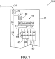
- a control cabinet 15 in a power distribution system 10 receives a power feed 20, which may be a single-phase alternating current (AC) power feed, a multi-phase AC power feed, or a direct current (DC) power feed according to the application requirements.
- a main circuit breaker 25 within the control cabinet 15 receives the power feed 20 and may be manually activated to enable/disable power within the control cabinet 15.
- the main circuit breaker 25 includes a first branch 27 and a second branch 29 at the output of the main circuit breaker 25.
- the illustrated embodiment is intended to be exemplary and illustrates only two branches for convenience. It is contemplated that any number of power branches may be distributed from the main circuit breaker 25.
- the first branch circuit 27 is connected to a secondary circuit breaker 30 and supplies power to an industrial controller 40.
- the industrial controller 40 may be, for example, a programmable logic controller (PLC) or a programmable activity controller (PAC).
- the illustrated industrial controller 40 includes a power supply module 42, a processor module 44, a network module 46, an input module 48 and an output module 50. It is contemplated that the industrial controller may be made up of numerous different modules connected together in a rack or mounted to a rail. Additional modules may be added or existing modules removed and the industrial controller 40 reconfigured to accommodate the new configuration. Optionally, the industrial controller 40 may have a predetermined and fixed configuration.
- the second branch circuit 29 includes still two additional branches.
- a third branch 51 is connected to multiple modular power distribution devices 80, 180, and a fourth branch 53 is shown extending on to still other devices not shown in the figure.
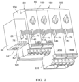
- the third branch 51 is connected to a communication module 60, two modular power distribution devices 80 which include a contactor module 120 (see Fig. 4 ) and to two modular power distribution devices 180 which include a motor starter 220 (see Fig. 3 ).
- the communication module 60 is part of an industrial network that extends between the industrial controller 40 and various devices within a machine or process that is being controlled by the industrial controller 40.
- a network cable 47 is connected between the network module 46 and the communication module 60. It is contemplated that the network cable 47 may be a custom cable configured to communicate via a proprietary interface or may be a standard industrial cable for a non-proprietary network. Exemplary non-proprietary networks include Ethernet/IP ® , DeviceNet ® , or ControlNet ® .
- the network cable 47 connects the industrial controller 40 to the communication module 60 in a point-to-point configuration.
- the network module 46 and communication module 60 are each configured to communicate according to the protocol of the network to which it is connected and may be further configured to translate messages between two different network protocols. Although illustrated as a wired network, where the connection is established via a network cable 47, it is further contemplated that the network may also include wireless connections.
- the communication module 60 includes a first port 62 configured to receive a connector on the network cable 47.
- the communication module 60 further includes a second port 64 configured to communicate with the modular power distribution devices 80, 180.
- a ribbon cable 70 has a terminal connector 72 on one end that plugs in to the second port 64 and pass-through connectors 74 that plug into a communication port 145 on each of the modular power distribution devices 80, 180.
- each of the modular power distribution devices 80, 180 may include a pair of communication ports 145 and separate cables, rather than a single ribbon cable, may be run between adjacent devices.
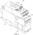
- a base 82 is provided on which a circuit protection device 100 and an electronically actuated power distribution device is mounted. It is contemplated that the electronically actuated power distribution device may be a contactor 120, motor starter 220, or motor drive (not shown). As illustrated in Fig. 4 , the electronically actuated power distribution device is a contactor 120.
- the base 82 includes a first side 84 configured to be mounted to a control panel and a second side 86, where the second side is opposite the first side.
- the first side 84 includes a channel 88 configured to receive a DIN rail within the channel. The DIN rail is first secured to the control panel and the modular power distribution device 80 is mounted, in turn, to the DIN rail.
- the second side 86 includes a first mounting section 90 and a second mounting section 92.
- the first mounting section 90 is configured to receive the circuit protection device 100
- the second mounting section 92 is configured to receive the electronically actuated power distribution device.
- the circuit protection device 100 slides on to the first mounting section 90.
- a flexible tab 91 may be deflected downward as the circuit protection device 100 is slid on to the base 82 and returns to its original position into a recess on the circuit protection device 100 as the circuit protection device fully engages the base 82 such that the flexible tab 91 positively retains the circuit protection device 100 on the base 82.
- the tab 91 may be manually deflected downward to release the circuit protection device 100 and to allow it to be slid off of the base 82.
- the contactor 120 slides on to the second mounting section 92.
- a flexible tab 93 may be deflected downward as the contactor 120 is slid on to the base 82 and returns to its original position into a recess on the contactor 120 as the contactor fully engages the base 82 such that the flexible tab 93 positively retains the contactor 120 on the base 82.
- the tab 93 may be manually deflected downward to release the contactor 120 and to allow it to be slid off of the base 82.
- Both the circuit protection device 100 and the electronically actuated power distribution device may be mounted to the base 82 without requiring a tool for mounting. Further, the base 82 may be snap fit onto the DIN rail such that each of the components in the modular power distribution device 80, 180 are mounted to the other without requiring tools for installation.
- each modular power distribution device 80, 180 is controlled to selectively supply power from the third branch 51 to a device on the controlled machine or process.
- the circuit protection device 100 includes a plurality of input terminals 102 configured to receive power conductors from the third power branch 51. It is contemplated that the circuit protection device 100 may be configured to receive single-phase AC voltage and include two input terminals 102 for power conductors. Single phase power includes a "hot" and a neutral conductor. Optionally, the circuit protection device 100 may be configured to receive a multi-phase (e.g., three-phase) AC voltage and include an input terminal 102 for each phase.
- a multi-phase e.g., three-phase
- the power conductors are electrical wires of suitable construction (e.g., solid or stranded) and of suitable wire gauge according to the current requirements of the application.
- the input terminals 102 may be screw terminals, as shown, requiring a screw driver for the connection of the conductors to the modular power distribution device 80.
- the input terminals 102 are connected through a switching member 103 to output connections 104 on the circuit protection device 100.
- the switching member 103 may be manually opened or closed.
- a dial 105, lever, or other such manual switching device is provided and may be turned, flipped, toggled, or the like to move the switching member 103 between an open and a closed position. In the open position, no current may be conducted through the circuit protection device 100. In the closed position, the current may be conducted, via the switching member 103 between the input terminals 102 and the output connections 104.
- the circuit protection device 100 also includes overcurrent protection.
- the overcurrent protection may be of any suitable method of detecting excessive current in the device including, but not limited to thermal, magnetic, or current transformers. When the current exceeds a rating for the circuit protection device 100, the switching member 103 is opened by the overcurrent protection.
- the circuit protection device may be manually or electronically reset after the excessive current flow is no longer present.
- the circuit protection device 100 selectively conducts the voltage from the branch circuit 51 to an electronically actuated power distribution device.
- the electronically actuated power distribution device may be a motor starter 220.
- the electronically actuated power distribution device may be a contactor 120.
- the electronically actuated power distribution device may be a motor drive.
- the electronically actuated power distribution device is any device that receives an electronic control signal and selectively delivers power from the circuit protection device 100 to another device in the controlled system.
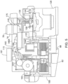
- the contactor 120 includes multiple input connections 122 and multiple output terminals 124.
- the input connections 122 are configured to engage the output connections 104 of the circuit protection device 100,
- the output connections 104 of the circuit protection device 100 are screw terminals, which are configured to receive the input connections 122 of the electronically actuated power distribution device 120.
- the input connections 122 are fixed metal conductors extending from the electronically actuated power distribution device 120. The distal end of each connection 122 is pronged such that it may fit around the screw in the screw terminal 104 of the circuit protection device 100.
- each pronged connector 122 on the electronically actuated power distribution device 120 is inserted into the corresponding output connection 104 of the circuit protection device 100 as the electronically actuated power distribution device 120 slides on to the base 82.
- the screw terminals may be required according to application requirements related, for example, to connecting power terminals of devices and to the current ratings of each device. It is contemplated that, if application requirements permit, the output connections 104 may include spring-terminals to positively engage the input connections 122 as the electronically actuated power distribution device is fit onto the base 82.
- the contactor 120 is configured to selectively connect the output terminals 124 with the input connections 122 of the contactor 1 20.
- a switching member 126 is movable between a first position (as shown) and a second position.
- the switching member 126 is a conductive material which includes a set of contacts 128 on one surface.
- a complementary set of contacts 128 are included on the interior end of the input connections 122 and the interior end of the output terminals 124. In the second position, the switching member 126 moves downward such that the contacts 128 on the switching member 126 engage the contacts 128 on the input connections 122 and the output terminals 124, thereby establishing an electrical conduction path therebetween.
- a control signal, received at the contactor 120 energizes an actuator, such as a coil clement, where the coil element establishes an electromagnetic field which, in turn, causes translation motion on a plunger, or metal rod within the coil element.
- the plunger is, in turn, connected to the switching member 126 to move the switching member between the open and closed position.
- a spring 130 causes the switching member 126 to return to its original position.
- a motor starter 220 may be fit onto the base 82 in the place of the contactor 120 previously discussed.
- the motor starter 220 is similarly configured with input connections configured to engage the output connections 104 of the circuit protection device 100.
- die motor starter 220 is configured to provide a variable output voltage at the output terminals 224.
- the output voltage may have a variable amplitude and frequency and is used to accelerate a motor connected to the output terminals 224 according to a predefined acceleration profile.
- the motor starter 220 may include a number of control parameters, configurable to define a desired acceleration profile.
- the motor starter 220 receives a control signal indicating operation of the motor connected to the output terminals 224 is desired and, in turn, accelerates the motor up to a desired operating speed and then maintains operation of the motor at the desired speed while the control signal is present.
- Each of the contactor 120 and the motor starter 220 require control signals in order to selectively provide the voltage from the circuit protection device 100 to a remote device connected at their respective output terminals 124, 224.
- An electronic control module 140 is connected to the modular power distribution device 80, 180 to receive these control signals.
- the electronic control module 140 is configured to physically mount to either the circuit protection device 100, the electronically actuated power distribution device 120, 220, or a combination thereof.
- a tab 150 protruding downward from the electronic control module 140 is configured to be snap fit to a complementary tab 135, 235.
- the tab on the electronic control module 140 extends down between the circuit protection device 100 and the electronically actuated power distribution device 80, 180, Consequently, the complementary tab may be on one device or the other.
- both devices may include a tab to more securely retain the electronic control module 140 to the modular power distribution device.
- the snap-fit of the electronic control module 140 allows the module to be mounted to the rest of the modular power distribution device 80, 180 without requiring a tool for installation.
- a first electronic control module 140A is illustrated in Fig. 4 as mounting to a contactor module 120
- a second electronic control module 140B is illustrated in Fig. 3 as mounting to a starter module 220. It is contemplated that the electronic control modules 140 include identical components but are sized differently to cover the respective electronically actuated power distribution device to which they are mounted.
- the electronic control module 140 includes a communication port 145 to which a ribbon cable connector 74 and the corresponding network cable 70 are connected.
- the ribbon cable 70 provides for a daisy chain connection between the communication module 60 and each modular power distribution device 80, 180.
- each electronic control module includes a printed circuit board 160 configured to include a control circuit.
- the control circuit is configured to receive data, such as control signals, from the communication port 145 and to transmit the control signals to either the circuit protection device 100 or the electronically actuated power distribution device 120, 220.
- the control circuit is also configured to receive feedback signals from either the circuit protection device 1 00 or the electronically actuated power distribution device 120, 220 and to package the feedback signals into data packets according to the network protocol for transmission from the communication port 145.
- the feedback signals correspond to the present operating conditions of either the circuit protection device 100 or the electronically actuated power distribution device 120, 220.
- the circuit protection device 100 may include, for example, a microswitch providing a signal corresponding to the status of the switching member 103.
- the circuit protection device 100 may also include a current transformer measuring an amplitude of current. As still another option, the circuit protection device 100 may generate a fault signal indicating when the overcurrent protection in the device has tripped. If the electronically actuated power distribution device includes a contactor module 120, feedback signals may be provided indicating whether the switching member 126 is in an open or closed state.
- the electronically actuated power distribution device is a motor starter module 220
- various feedback signals may be generated indicating, for example, when the motor is accelerating, up to speed, at zero speed or the like.
- Each of the control signals and/or feedback signals corresponds to a signal which traditionally has been transferred back to a central controller 40 via individual conductors. Transmitting the control signals and/or feedback signals via the ribbon cable 70 reduces wiring complexity and the potential for wiring errors.
- a first electrical connection is established between a first connector 165 on the circuit board 160 and a complementary connector 115 on the circuit protection device 100.
- a second electrical connection is established between a second connector 175 on the circuit board 160 and a complementary connector 137 on the electronically actuated power distribution device 120, 220.
- the first and second electrical connectors 165, 175 on the circuit board 160 are configured such that each may be press-fit, snap-fit, or the like as the electronic control module 140 is being connected to the circuit protection device 100 and/or the electronically actuated power distribution device. The resultant first and second electrical connections are thereby established without requiring a tool or any additional wiring to make the interconnections.
Landscapes
- Physics & Mathematics (AREA)
- Electromagnetism (AREA)
- Engineering & Computer Science (AREA)
- Power Engineering (AREA)
- Breakers (AREA)
- Patch Boards (AREA)
- Distribution Board (AREA)
Claims (13)
- Modulare Leistungsverteilungsvorrichtung (80; 180), umfassend:eine Basis (82) mit einer ersten Seite (84) und einer zweiten Seite (86), wobei:die erste Seite dazu konfiguriert ist, an einem Bedienfeld befestigt zu werden,die zweite Seite der ersten Seite gegenüberliegt,die zweite Seite einen ersten Montageabschnitt (90) und einen zweiten Montageabschnitt (92) enthält;eine Schaltungsschutzvorrichtung (100), die dazu konfiguriert ist, an dem ersten Montageabschnitt der Basis montiert zu werden, wobei die Schaltungsschutzvorrichtung Folgendes beinhaltet:eine Vielzahl von Eingangsklemmen (102), die dazu konfiguriert sind, Stromleiter aufzunehmen, undeine Vielzahl von Ausgangsanschlüssen (104);eine elektronisch betätigte Leistungsverteilungsvorrichtung (120; 220), die dazu konfiguriert ist, an dem zweiten Montageabschnitt der Basis montiert zu werden, wobei die elektronisch betätigte Leistungsverteilungsvorrichtung Folgendes beinhaltet:eine Vielzahl von Eingangsanschlüssen (122), wobei die Vielzahl von Eingangsanschlüssen dazu konfiguriert ist, mit der Vielzahl von Ausgangsanschlüssen der Schaltungsschutzvorrichtung verbunden zu werden; undeine Vielzahl von Ausgangsklemmen (124), die dazu konfiguriert ist, Leiter zur Stromversorgung einer gesteuerten Vorrichtung aufzunehmen, wobei die elektronisch betätigte Leistungsverteilungsvorrichtung dazu konfiguriert ist, gleitend in den zweiten Montageabschnitt der Basis einzugreifen und die Vielzahl von Eingangsanschlüssen an der elektronisch betätigten Leistungsverteilungsvorrichtung dazu konfiguriert ist, gleitend in die Vielzahl von Ausgangsanschlüssen an der Schaltungsschutzvorrichtung einzugreifen, wenn die elektronisch betätigte Leistungsverteilungsvorrichtung gleitend in den zweiten Montageabschnitt eingreift; undein elektronisches Steuermodul (140), das dazu konfiguriert ist, entweder an der Schaltungsschutzvorrichtung oder an der elektronisch betätigten Leistungsverteilungsvorrichtung physisch montiert zu werden, wobei das elektronische Steuermodul Folgendes beinhaltet:einen Stecker (145), der dazu konfiguriert ist, eine Netzwerkverbindung aufzunehmen,eine elektrische Verbindung (165) zu der Schaltungsschutzvorrichtung, undeine elektrische Verbindung (175) zu der elektronisch betätigten Leistungsverteilungsvorrichtung.
- Modulare Leistungsverteilungsvorrichtung nach Anspruch 1, wobei:der Schaltungsschutz dazu konfiguriert ist, an dem ersten Montageabschnitt der Basis befestigt zu werden, ohne dass ein Werkzeug für die Montage erforderlich ist;die elektronisch betätigte Leistungsverteilungsvorrichtung dazu konfiguriert ist, an dem zweiten Montageabschnitt der Basis montiert zu werden, ohne dass ein Werkzeug für die Montage erforderlich ist; unddas elektronische Steuermodul dazu konfiguriert ist, entweder an der Schaltungsschutzvorrichtung oder an der elektronisch betätigten Leistungsverteilungsvorrichtung physisch montiert zu werden, ohne dass ein Werkzeug für die Montage erforderlich ist.
- Modulare Leistungsverteilungsvorrichtung nach Anspruch 1 oder 2, wobei die elektronisch betätigte Leistungsverteilungsvorrichtung entweder ein Schütz oder ein Motorstarter ist.
- Modulare Leistungsverteilungsvorrichtung nach einem der Ansprüche 1 bis 3, wobei die erste Seite der Basis dazu konfiguriert ist, an einer DIN-Schiene montiert zu werden; oder
wobei die Schaltungsschutzvorrichtung dazu konfiguriert ist, gleitend in den ersten Montageabschnitt einzugreifen. - Modulare Leistungsverteilungsvorrichtung nach einem der Ansprüche 1 bis 4, wobei die Basis eine Lasche (91) enthält, die dazu konfiguriert ist, sich nach unten zu biegen, wenn die elektronisch betätigte Leistungsverteilungsvorrichtung auf der Basis gleitet, und in eine ursprüngliche Position zurückzukehren, wenn sich die elektronisch betätigte Leistungsverteilungsvorrichtung auf der Basis befindet, und wobei die Lasche dazu konfiguriert ist, die elektronisch betätigte Leistungsverteilungsvorrichtung auf der Basis festzuhalten.
- Modulare Leistungsverteilungsvorrichtung nach einem der Ansprüche 1 bis 5, wobei:de Netzwerkverbindung dazu konfiguriert ist, ein Netzwerkkabel (70) aufzunehmen,mindestens ein Steuersignal über das Netzwerkkabel an die elektronisch betätigte Leistungsverteilungsvorrichtung geliefert wird, unddas Steuersignal dazu konfiguriert ist, die elektronisch betätigte Stromverteilungsvorrichtung selektiv zu aktivieren; und/oderwobei das Netzwerkkabel ferner dazu konfiguriert ist, mindestens ein Rückkopplungssignal von der modularen Leistungsverteilungsvorrichtung an eine entfernte Vorrichtung zu übertragen.
- Modulare Leistungsverteilungsvorrichtung nach einem der Ansprüche 1 bis 6, wobei das elektronische Steuermodul eine Kommunikationsschnittstelle enthält, die dazu konfiguriert ist, Datenpakete über die Netzwerkverbindung zu übertragen und zu empfangen.
- Modulares Leistungsverteilungssystem, umfassend:ein Kommunikationsmodul (60) mit einem ersten Anschluss (62), der dazu konfiguriert ist, mit einem industriellen Netzwerk verbunden zu werden, und einem zweiten Anschluss (64), der dazu konfiguriert ist, mit einer Vielzahl von industriellen Steuervorrichtungen verbunden zu werden; unddie modulare Leistungsverteilungsvorrichtung nach Anspruch 1, wobei:die Schaltungsschutzvorrichtung dazu konfiguriert ist, gleitend in den ersten Montageabschnitt der Basis einzugreifen; unddas elektronische Steuermodul dazu konfiguriert ist, über eine Schnappverbindung entweder an der Schaltungsschutzvorrichtung oder an der elektronisch betätigten Leistungsverteilungsvorrichtung befestigt zu werden.
- Modulares Leistungsverteilungssystem nach Anspruch 8, wobei die elektronisch betätigte Leistungsverteilungsvorrichtung entweder ein Schütz oder ein Motorstarter ist; oder wobei die Basis dazu konfiguriert ist, an einer DIN-Schiene befestigt zu werden.
- Modulares Leistungsverteilungssystem nach einem der Ansprüche 8 bis 9, wobei die Basis eine Lasche (91) enthält, die dazu konfiguriert ist, sich nach unten zu biegen, wenn die elektronisch betätigte Leistungsverteilungsvorrichtung auf der Basis gleitet, und in eine ursprüngliche Position zurückzukehren, wenn sich die elektronisch betätigte Leistungsverteilungsvorrichtung auf der Basis befindet, und wobei die Lasche dazu konfiguriert ist, die elektronisch betätigte Leistungsverteilungsvorrichtung auf der Basis festzuhalten.
- Modulares Leistungsverteilungssystem nach einem der Ansprüche 8 bis 10, wobei das Kommunikationsmodul zu Folgendem konfiguriert ist:Aufnehmen eines Netzwerkkabels von dem industriellen Netzwerk an dem ersten Anschluss, undAufnehmen eines Verbindungskabels am zweiten Anschluss, wobei das Verbindungskabel dazu konfiguriert ist, eine funktionsfähige Verbindung zwischen dem Kommunikationsmodul und jeder der mindestens einen modularen Leistungsverteilungsvorrichtungen herzustellen.
- Modulares Leistungsverteilungssystem nach Anspruch 11, wobei das Kommunikationsmodul zu Folgendem konfiguriert ist:Empfangen einer Vielzahl von Datenpaketen in einem ersten Protokoll von dem industriellen Netzwerk,Umwandeln der Vielzahl von Datenpaketen im ersten Protokoll in einen ersten Satz von umgewandelten Datenpaketen in einem zweiten Protokoll,Übertragen des ersten Satzes konvertierter Datenpakete über das Verbindungskabel,Empfangen einer Vielzahl von Datenpaketen in dem zweiten Protokoll von dem Verbindungskabel, Umwandeln der Vielzahl von Datenpaketen in dem zweiten Protokoll in einen zweiten Satz von umgewandelten Datenpaketen in dem ersten Protokoll, undÜbertragen des zweiten Satzes von umgewandelten Datenpaketen über das industrielle Netzwerk.
- Modulares Leistungsverteilungssystem nach Anspruch 12, wobei:die Vielzahl von Datenpaketen im ersten Protokoll mindestens ein Steuersignal enthält, um die elektronisch betätigte Leistungsverteilungsvorrichtung selektiv zu aktivieren, unddas Kommunikationsmodul das Steuersignal über das zweite Protokoll an die elektronisch betätigte Leistungsverteilungsvorrichtung liefert; oderwobei:wobei das Kommunikationsmodul dazu konfiguriert ist, mindestens ein Rückkopplungssignal von der modularen Leistungsverteilungsvorrichtung über das zweite Protokoll zu empfangen, unddas Kommunikationsmodul das mindestens eine Rückkopplungssignal über das erste Protokoll im industriellen Netzwerk an eine entfernte Vorrichtung überträgt; oderwobei das elektronische Steuermodul eine Kommunikationsschnittstelle enthält, die zum Übertragen und Empfangen von Datenpaketen im zweiten Protokoll über das Verbindungskabel konfiguriert ist.
Applications Claiming Priority (1)
| Application Number | Priority Date | Filing Date | Title |
|---|---|---|---|
| US17/039,096 US11515691B2 (en) | 2020-09-30 | 2020-09-30 | Modular low voltage power distribution module |
Publications (2)
| Publication Number | Publication Date |
|---|---|
| EP3979294A1 EP3979294A1 (de) | 2022-04-06 |
| EP3979294B1 true EP3979294B1 (de) | 2024-09-25 |
Family
ID=77398442
Family Applications (1)
| Application Number | Title | Priority Date | Filing Date |
|---|---|---|---|
| EP21191864.4A Active EP3979294B1 (de) | 2020-09-30 | 2021-08-18 | Modulares niederspannungs-stromverteilungsmodul |
Country Status (3)
| Country | Link |
|---|---|
| US (1) | US11515691B2 (de) |
| EP (1) | EP3979294B1 (de) |
| CN (1) | CN114336292B (de) |
Families Citing this family (4)
| Publication number | Priority date | Publication date | Assignee | Title |
|---|---|---|---|---|
| DE102019216197A1 (de) * | 2019-10-21 | 2021-04-22 | Ellenberger & Poensgen Gmbh | Schalteinheit zur Montage auf einer Tragschiene |
| US11778759B2 (en) * | 2021-01-04 | 2023-10-03 | Rockwell Automation Technologies, Inc. | Universal control module for a reversing contactor |
| CN117750573A (zh) * | 2023-12-20 | 2024-03-22 | 广州彩熠灯光股份有限公司 | 脉宽调制信号识别方法、装置、设备和存储介质 |
| DE102024209749A1 (de) * | 2024-10-07 | 2026-04-09 | Siemens Aktiengesellschaft | Abzweig zum Anbinden eines Verbrauchers |
Family Cites Families (22)
| Publication number | Priority date | Publication date | Assignee | Title |
|---|---|---|---|---|
| DE4335965A1 (de) | 1993-10-21 | 1995-04-27 | Licentia Gmbh | Motorstarter mit integriertem Kurzschlußschutz |
| DE9403259U1 (de) | 1994-02-26 | 1994-04-21 | Klöckner-Moeller GmbH, 53115 Bonn | Gehäuseaufbau für einen Niederspannungs-Schutzschalter mit Hilfsschalterblock |
| US5652420A (en) * | 1995-11-14 | 1997-07-29 | Eaton Corporation | Modular contactor control system |
| FR2761539B1 (fr) | 1997-04-01 | 1999-05-14 | Schneider Electric Sa | Ensemble de depart-moteur a circuit imprime |
| FR2761538B1 (fr) * | 1997-04-01 | 1999-05-14 | Schneider Electric Sa | Ensemble de depart-moteur |
| DE19748429A1 (de) * | 1997-11-03 | 1999-05-06 | Siemens Ag | Kommunikationsfähige Schaltgeräteeinheit |
| DE19748531A1 (de) * | 1997-11-03 | 1999-05-06 | Siemens Ag | Aufbausystem für Verbraucherabzweige mit stehender Verdrahtung |
| FR2776861B1 (fr) * | 1998-03-27 | 2000-05-19 | Schneider Electric Sa | Ensemble de depart-moteur |
| FR2805094B1 (fr) * | 2000-02-14 | 2002-03-29 | Schneider Electric Ind Sa | Ensemble de depart-moteur |
| DE10023966C1 (de) | 2000-05-16 | 2001-11-08 | Siemens Ag | Verbraucherabzweig |
| DE10119458B4 (de) * | 2001-04-20 | 2004-08-19 | Siemens Ag | Schaltgeräteeinheit für einen Verbraucher, insbesondere Motorstarter |
| FR2837618B1 (fr) * | 2002-03-19 | 2004-05-28 | Schneider Electric Ind Sa | Bloc additif pour contacteur-disjoncteur |
| CN102683134A (zh) * | 2012-06-06 | 2012-09-19 | 伊发控股集团有限公司 | 控制与保护开关电器 |
| CN203038864U (zh) | 2012-12-28 | 2013-07-03 | 常熟开关制造有限公司(原常熟开关厂) | 一种控制与保护开关电器 |
| CN203039282U (zh) * | 2012-12-28 | 2013-07-03 | 常熟开关制造有限公司(原常熟开关厂) | 控制与保护开关电器的连接模块 |
| DE102015115197A1 (de) | 2015-09-09 | 2017-03-09 | Eaton Electrical Ip Gmbh & Co. Kg | Anschlussadapter für ein Stromschieneneinspeisesystem |
| FR3053829B1 (fr) | 2016-07-08 | 2019-10-25 | Schneider Electric Industries Sas | Module d'interconnexion d'un disjoncteur et d'un contacteur pour un ensemble electrique comportant un capteur de tension |
| EP3340269B1 (de) | 2016-12-21 | 2019-11-27 | ABB Schweiz AG | Multipolares elektrogerät mit vertikal ausgerichteter anschlussklemme für steckanschluss, und elektrisches unterbrechungssystem |
| FR3069716B1 (fr) | 2017-07-25 | 2019-09-06 | Schneider Electric Industries Sas | Dispositif electrique pour l'alimentation electrique d'appareils electriques de puissance |
| CN207353174U (zh) * | 2017-08-31 | 2018-05-11 | 扬州奥帆电器有限公司 | 一种控制保护开关的基座 |
| WO2020069584A1 (pt) * | 2018-10-04 | 2020-04-09 | Weg Drives & Controls - Automação Ltda. | Conjunto de módulos auxiliares para conjunto de chave de partida para motores elétricos |
| FR3108800B1 (fr) * | 2020-03-24 | 2022-07-15 | Schneider Electric Ind Sas | Dispositif electrique pour l’alimentation electrique d’appareils electriques de puissance |
-
2020
- 2020-09-30 US US17/039,096 patent/US11515691B2/en active Active
-
2021
- 2021-08-17 CN CN202110943040.XA patent/CN114336292B/zh active Active
- 2021-08-18 EP EP21191864.4A patent/EP3979294B1/de active Active
Also Published As
| Publication number | Publication date |
|---|---|
| EP3979294A1 (de) | 2022-04-06 |
| CN114336292B (zh) | 2024-11-01 |
| US20220102103A1 (en) | 2022-03-31 |
| US11515691B2 (en) | 2022-11-29 |
| CN114336292A (zh) | 2022-04-12 |
Similar Documents
| Publication | Publication Date | Title |
|---|---|---|
| EP3979294A1 (de) | Modulares niederspannungs-stromverteilungsmodul | |
| US20080137266A1 (en) | Motor control center with power and data distribution bus | |
| US4935863A (en) | Control and protection assembly connecting a local area communication network to an industrial process | |
| JP4741638B2 (ja) | スイッチギア装置のためのグループ保護モジュール及びかかるグループ保護モジュールを有するスイッチギア装置 | |
| EP1964222B1 (de) | Stromverteilungssystem mit individuell isolierbaren funktionalen zonen | |
| JP2009022158A6 (ja) | スイッチギア装置のためのグループ保護モジュール及びかかるグループ保護モジュールを有するスイッチギア装置 | |
| EP3798770B1 (de) | Abnehmbare anschlussblock anordnung, die einer i/o-basis erlaubt, im simplexmodus oder duplexmodus zu arbeiten | |
| US5978193A (en) | Switchgear unit capable of communication | |
| US8884569B2 (en) | Secure motor starter | |
| MX2014001311A (es) | Interruptor electrico de prueba. | |
| EP3751972B1 (de) | Isolierter intelligenter leistungsanschlussblock | |
| CA2519454C (en) | Low-voltage module | |
| US8148654B2 (en) | Medium-voltage or high-voltage switching or control device, in particular a switchgear assembly | |
| US7161318B2 (en) | Regulating device for a motor | |
| US8278780B2 (en) | Switching device and system with switching device | |
| US7508093B2 (en) | Modular current supply | |
| US8248762B2 (en) | Reliable asynchronous serial protocol between remote operated devices and input/output controller | |
| US20220247159A1 (en) | Switch assembly for mounting on a mounting rail | |
| CN111010212A (zh) | 用于低压和中压开关装置的附属装置 | |
| US20050094343A1 (en) | Decentralized control of motors | |
| CN108879540B (zh) | 配电系统和组装配电系统的方法 | |
| CN101176177A (zh) | 一种用于容纳和连接开关附件的装置 | |
| EP1770738B1 (de) | Verfahren und Vorrichtung zur Regelung der Zufuhr elektrischer Leistung | |
| EP4160836A2 (de) | Systeme und verfahren für buskabel und verbinder einer motorsteuerungszentrale | |
| US8564420B2 (en) | Control module with connection devices for connection to connection terminals of a load feeder and load feeder |
Legal Events
| Date | Code | Title | Description |
|---|---|---|---|
| PUAI | Public reference made under article 153(3) epc to a published international application that has entered the european phase |
Free format text: ORIGINAL CODE: 0009012 |
|
| STAA | Information on the status of an ep patent application or granted ep patent |
Free format text: STATUS: THE APPLICATION HAS BEEN PUBLISHED |
|
| AK | Designated contracting states |
Kind code of ref document: A1 Designated state(s): AL AT BE BG CH CY CZ DE DK EE ES FI FR GB GR HR HU IE IS IT LI LT LU LV MC MK MT NL NO PL PT RO RS SE SI SK SM TR |
|
| STAA | Information on the status of an ep patent application or granted ep patent |
Free format text: STATUS: REQUEST FOR EXAMINATION WAS MADE |
|
| 17P | Request for examination filed |
Effective date: 20220929 |
|
| RBV | Designated contracting states (corrected) |
Designated state(s): AL AT BE BG CH CY CZ DE DK EE ES FI FR GB GR HR HU IE IS IT LI LT LU LV MC MK MT NL NO PL PT RO RS SE SI SK SM TR |
|
| GRAP | Despatch of communication of intention to grant a patent |
Free format text: ORIGINAL CODE: EPIDOSNIGR1 |
|
| STAA | Information on the status of an ep patent application or granted ep patent |
Free format text: STATUS: GRANT OF PATENT IS INTENDED |
|
| RIC1 | Information provided on ipc code assigned before grant |
Ipc: H02B 1/056 20060101ALN20240416BHEP Ipc: H02B 1/42 20060101ALN20240416BHEP Ipc: H02B 1/32 20060101ALN20240416BHEP Ipc: H01H 89/00 20060101ALN20240416BHEP Ipc: H01H 89/06 20060101AFI20240416BHEP |
|
| INTG | Intention to grant announced |
Effective date: 20240430 |
|
| GRAS | Grant fee paid |
Free format text: ORIGINAL CODE: EPIDOSNIGR3 |
|
| GRAA | (expected) grant |
Free format text: ORIGINAL CODE: 0009210 |
|
| STAA | Information on the status of an ep patent application or granted ep patent |
Free format text: STATUS: THE PATENT HAS BEEN GRANTED |
|
| AK | Designated contracting states |
Kind code of ref document: B1 Designated state(s): AL AT BE BG CH CY CZ DE DK EE ES FI FR GB GR HR HU IE IS IT LI LT LU LV MC MK MT NL NO PL PT RO RS SE SI SK SM TR |
|
| REG | Reference to a national code |
Ref country code: GB Ref legal event code: FG4D |
|
| REG | Reference to a national code |
Ref country code: CH Ref legal event code: EP |
|
| REG | Reference to a national code |
Ref country code: DE Ref legal event code: R096 Ref document number: 602021019215 Country of ref document: DE |
|
| REG | Reference to a national code |
Ref country code: IE Ref legal event code: FG4D |
|
| REG | Reference to a national code |
Ref country code: LT Ref legal event code: MG9D |
|
| PG25 | Lapsed in a contracting state [announced via postgrant information from national office to epo] |
Ref country code: NO Free format text: LAPSE BECAUSE OF FAILURE TO SUBMIT A TRANSLATION OF THE DESCRIPTION OR TO PAY THE FEE WITHIN THE PRESCRIBED TIME-LIMIT Effective date: 20241225 |
|
| PG25 | Lapsed in a contracting state [announced via postgrant information from national office to epo] |
Ref country code: GR Free format text: LAPSE BECAUSE OF FAILURE TO SUBMIT A TRANSLATION OF THE DESCRIPTION OR TO PAY THE FEE WITHIN THE PRESCRIBED TIME-LIMIT Effective date: 20241226 Ref country code: FI Free format text: LAPSE BECAUSE OF FAILURE TO SUBMIT A TRANSLATION OF THE DESCRIPTION OR TO PAY THE FEE WITHIN THE PRESCRIBED TIME-LIMIT Effective date: 20240925 |
|
| PG25 | Lapsed in a contracting state [announced via postgrant information from national office to epo] |
Ref country code: BG Free format text: LAPSE BECAUSE OF FAILURE TO SUBMIT A TRANSLATION OF THE DESCRIPTION OR TO PAY THE FEE WITHIN THE PRESCRIBED TIME-LIMIT Effective date: 20240925 |
|
| PG25 | Lapsed in a contracting state [announced via postgrant information from national office to epo] |
Ref country code: LV Free format text: LAPSE BECAUSE OF FAILURE TO SUBMIT A TRANSLATION OF THE DESCRIPTION OR TO PAY THE FEE WITHIN THE PRESCRIBED TIME-LIMIT Effective date: 20240925 |
|
| PG25 | Lapsed in a contracting state [announced via postgrant information from national office to epo] |
Ref country code: RS Free format text: LAPSE BECAUSE OF FAILURE TO SUBMIT A TRANSLATION OF THE DESCRIPTION OR TO PAY THE FEE WITHIN THE PRESCRIBED TIME-LIMIT Effective date: 20241225 |
|
| REG | Reference to a national code |
Ref country code: NL Ref legal event code: MP Effective date: 20240925 |
|
| PG25 | Lapsed in a contracting state [announced via postgrant information from national office to epo] |
Ref country code: RS Free format text: LAPSE BECAUSE OF FAILURE TO SUBMIT A TRANSLATION OF THE DESCRIPTION OR TO PAY THE FEE WITHIN THE PRESCRIBED TIME-LIMIT Effective date: 20241225 Ref country code: NO Free format text: LAPSE BECAUSE OF FAILURE TO SUBMIT A TRANSLATION OF THE DESCRIPTION OR TO PAY THE FEE WITHIN THE PRESCRIBED TIME-LIMIT Effective date: 20241225 Ref country code: LV Free format text: LAPSE BECAUSE OF FAILURE TO SUBMIT A TRANSLATION OF THE DESCRIPTION OR TO PAY THE FEE WITHIN THE PRESCRIBED TIME-LIMIT Effective date: 20240925 Ref country code: GR Free format text: LAPSE BECAUSE OF FAILURE TO SUBMIT A TRANSLATION OF THE DESCRIPTION OR TO PAY THE FEE WITHIN THE PRESCRIBED TIME-LIMIT Effective date: 20241226 Ref country code: FI Free format text: LAPSE BECAUSE OF FAILURE TO SUBMIT A TRANSLATION OF THE DESCRIPTION OR TO PAY THE FEE WITHIN THE PRESCRIBED TIME-LIMIT Effective date: 20240925 Ref country code: BG Free format text: LAPSE BECAUSE OF FAILURE TO SUBMIT A TRANSLATION OF THE DESCRIPTION OR TO PAY THE FEE WITHIN THE PRESCRIBED TIME-LIMIT Effective date: 20240925 |
|
| REG | Reference to a national code |
Ref country code: AT Ref legal event code: MK05 Ref document number: 1727397 Country of ref document: AT Kind code of ref document: T Effective date: 20240925 |
|
| PG25 | Lapsed in a contracting state [announced via postgrant information from national office to epo] |
Ref country code: NL Free format text: LAPSE BECAUSE OF FAILURE TO SUBMIT A TRANSLATION OF THE DESCRIPTION OR TO PAY THE FEE WITHIN THE PRESCRIBED TIME-LIMIT Effective date: 20240925 |
|
| PG25 | Lapsed in a contracting state [announced via postgrant information from national office to epo] |
Ref country code: IS Free format text: LAPSE BECAUSE OF FAILURE TO SUBMIT A TRANSLATION OF THE DESCRIPTION OR TO PAY THE FEE WITHIN THE PRESCRIBED TIME-LIMIT Effective date: 20250125 Ref country code: PT Free format text: LAPSE BECAUSE OF FAILURE TO SUBMIT A TRANSLATION OF THE DESCRIPTION OR TO PAY THE FEE WITHIN THE PRESCRIBED TIME-LIMIT Effective date: 20250127 |
|
| PG25 | Lapsed in a contracting state [announced via postgrant information from national office to epo] |
Ref country code: RO Free format text: LAPSE BECAUSE OF FAILURE TO SUBMIT A TRANSLATION OF THE DESCRIPTION OR TO PAY THE FEE WITHIN THE PRESCRIBED TIME-LIMIT Effective date: 20240925 Ref country code: SM Free format text: LAPSE BECAUSE OF FAILURE TO SUBMIT A TRANSLATION OF THE DESCRIPTION OR TO PAY THE FEE WITHIN THE PRESCRIBED TIME-LIMIT Effective date: 20240925 |
|
| PG25 | Lapsed in a contracting state [announced via postgrant information from national office to epo] |
Ref country code: ES Free format text: LAPSE BECAUSE OF FAILURE TO SUBMIT A TRANSLATION OF THE DESCRIPTION OR TO PAY THE FEE WITHIN THE PRESCRIBED TIME-LIMIT Effective date: 20240925 |
|
| PG25 | Lapsed in a contracting state [announced via postgrant information from national office to epo] |
Ref country code: AT Free format text: LAPSE BECAUSE OF FAILURE TO SUBMIT A TRANSLATION OF THE DESCRIPTION OR TO PAY THE FEE WITHIN THE PRESCRIBED TIME-LIMIT Effective date: 20240925 Ref country code: EE Free format text: LAPSE BECAUSE OF FAILURE TO SUBMIT A TRANSLATION OF THE DESCRIPTION OR TO PAY THE FEE WITHIN THE PRESCRIBED TIME-LIMIT Effective date: 20240925 |
|
| PG25 | Lapsed in a contracting state [announced via postgrant information from national office to epo] |
Ref country code: CZ Free format text: LAPSE BECAUSE OF FAILURE TO SUBMIT A TRANSLATION OF THE DESCRIPTION OR TO PAY THE FEE WITHIN THE PRESCRIBED TIME-LIMIT Effective date: 20240925 Ref country code: PL Free format text: LAPSE BECAUSE OF FAILURE TO SUBMIT A TRANSLATION OF THE DESCRIPTION OR TO PAY THE FEE WITHIN THE PRESCRIBED TIME-LIMIT Effective date: 20240925 |
|
| PG25 | Lapsed in a contracting state [announced via postgrant information from national office to epo] |
Ref country code: IT Free format text: LAPSE BECAUSE OF FAILURE TO SUBMIT A TRANSLATION OF THE DESCRIPTION OR TO PAY THE FEE WITHIN THE PRESCRIBED TIME-LIMIT Effective date: 20240925 Ref country code: SK Free format text: LAPSE BECAUSE OF FAILURE TO SUBMIT A TRANSLATION OF THE DESCRIPTION OR TO PAY THE FEE WITHIN THE PRESCRIBED TIME-LIMIT Effective date: 20240925 |
|
| REG | Reference to a national code |
Ref country code: DE Ref legal event code: R097 Ref document number: 602021019215 Country of ref document: DE |
|
| PG25 | Lapsed in a contracting state [announced via postgrant information from national office to epo] |
Ref country code: DK Free format text: LAPSE BECAUSE OF FAILURE TO SUBMIT A TRANSLATION OF THE DESCRIPTION OR TO PAY THE FEE WITHIN THE PRESCRIBED TIME-LIMIT Effective date: 20240925 |
|
| PLBE | No opposition filed within time limit |
Free format text: ORIGINAL CODE: 0009261 |
|
| STAA | Information on the status of an ep patent application or granted ep patent |
Free format text: STATUS: NO OPPOSITION FILED WITHIN TIME LIMIT |
|
| 26N | No opposition filed |
Effective date: 20250626 |
|
| PG25 | Lapsed in a contracting state [announced via postgrant information from national office to epo] |
Ref country code: SE Free format text: LAPSE BECAUSE OF FAILURE TO SUBMIT A TRANSLATION OF THE DESCRIPTION OR TO PAY THE FEE WITHIN THE PRESCRIBED TIME-LIMIT Effective date: 20240925 |
|
| PGFP | Annual fee paid to national office [announced via postgrant information from national office to epo] |
Ref country code: DE Payment date: 20250724 Year of fee payment: 5 |
|
| PGFP | Annual fee paid to national office [announced via postgrant information from national office to epo] |
Ref country code: GB Payment date: 20250724 Year of fee payment: 5 |
|
| PGFP | Annual fee paid to national office [announced via postgrant information from national office to epo] |
Ref country code: FR Payment date: 20250723 Year of fee payment: 5 |
|
| PG25 | Lapsed in a contracting state [announced via postgrant information from national office to epo] |
Ref country code: HR Free format text: LAPSE BECAUSE OF FAILURE TO SUBMIT A TRANSLATION OF THE DESCRIPTION OR TO PAY THE FEE WITHIN THE PRESCRIBED TIME-LIMIT Effective date: 20240925 |
|
| REG | Reference to a national code |
Ref country code: CH Ref legal event code: H13 Free format text: ST27 STATUS EVENT CODE: U-0-0-H10-H13 (AS PROVIDED BY THE NATIONAL OFFICE) Effective date: 20260324 |
|
| PG25 | Lapsed in a contracting state [announced via postgrant information from national office to epo] |
Ref country code: MC Free format text: LAPSE BECAUSE OF FAILURE TO SUBMIT A TRANSLATION OF THE DESCRIPTION OR TO PAY THE FEE WITHIN THE PRESCRIBED TIME-LIMIT Effective date: 20240925 |
|
| PG25 | Lapsed in a contracting state [announced via postgrant information from national office to epo] |
Ref country code: LU Free format text: LAPSE BECAUSE OF NON-PAYMENT OF DUE FEES Effective date: 20250818 |
|
| PG25 | Lapsed in a contracting state [announced via postgrant information from national office to epo] |
Ref country code: CH Free format text: LAPSE BECAUSE OF NON-PAYMENT OF DUE FEES Effective date: 20250831 |