EP3978829A1 - Refrigeration cycle device and refrigerator - Google Patents
Refrigeration cycle device and refrigerator Download PDFInfo
- Publication number
- EP3978829A1 EP3978829A1 EP19931481.6A EP19931481A EP3978829A1 EP 3978829 A1 EP3978829 A1 EP 3978829A1 EP 19931481 A EP19931481 A EP 19931481A EP 3978829 A1 EP3978829 A1 EP 3978829A1
- Authority
- EP
- European Patent Office
- Prior art keywords
- refrigerant
- compressor
- evaporator
- refrigeration cycle
- cycle apparatus
- Prior art date
- Legal status (The legal status is an assumption and is not a legal conclusion. Google has not performed a legal analysis and makes no representation as to the accuracy of the status listed.)
- Withdrawn
Links
Images


Classifications
-
- F—MECHANICAL ENGINEERING; LIGHTING; HEATING; WEAPONS; BLASTING
- F04—POSITIVE - DISPLACEMENT MACHINES FOR LIQUIDS; PUMPS FOR LIQUIDS OR ELASTIC FLUIDS
- F04B—POSITIVE-DISPLACEMENT MACHINES FOR LIQUIDS; PUMPS
- F04B39/00—Component parts, details, or accessories, of pumps or pumping systems specially adapted for elastic fluids, not otherwise provided for in, or of interest apart from, groups F04B25/00 - F04B37/00
- F04B39/02—Lubrication
-
- F—MECHANICAL ENGINEERING; LIGHTING; HEATING; WEAPONS; BLASTING
- F04—POSITIVE - DISPLACEMENT MACHINES FOR LIQUIDS; PUMPS FOR LIQUIDS OR ELASTIC FLUIDS
- F04B—POSITIVE-DISPLACEMENT MACHINES FOR LIQUIDS; PUMPS
- F04B35/00—Piston pumps specially adapted for elastic fluids and characterised by the driving means to their working members, or by combination with, or adaptation to, specific driving engines or motors, not otherwise provided for
- F04B35/04—Piston pumps specially adapted for elastic fluids and characterised by the driving means to their working members, or by combination with, or adaptation to, specific driving engines or motors, not otherwise provided for the means being electric
-
- F—MECHANICAL ENGINEERING; LIGHTING; HEATING; WEAPONS; BLASTING
- F04—POSITIVE - DISPLACEMENT MACHINES FOR LIQUIDS; PUMPS FOR LIQUIDS OR ELASTIC FLUIDS
- F04B—POSITIVE-DISPLACEMENT MACHINES FOR LIQUIDS; PUMPS
- F04B39/00—Component parts, details, or accessories, of pumps or pumping systems specially adapted for elastic fluids, not otherwise provided for in, or of interest apart from, groups F04B25/00 - F04B37/00
- F04B39/02—Lubrication
- F04B39/0223—Lubrication characterised by the compressor type
- F04B39/023—Hermetic compressors
-
- F—MECHANICAL ENGINEERING; LIGHTING; HEATING; WEAPONS; BLASTING
- F25—REFRIGERATION OR COOLING; COMBINED HEATING AND REFRIGERATION SYSTEMS; HEAT PUMP SYSTEMS; MANUFACTURE OR STORAGE OF ICE; LIQUEFACTION SOLIDIFICATION OF GASES
- F25B—REFRIGERATION MACHINES, PLANTS OR SYSTEMS; COMBINED HEATING AND REFRIGERATION SYSTEMS; HEAT PUMP SYSTEMS
- F25B31/00—Compressor arrangements
- F25B31/02—Compressor arrangements of motor-compressor units
- F25B31/026—Compressor arrangements of motor-compressor units with compressor of rotary type
-
- F—MECHANICAL ENGINEERING; LIGHTING; HEATING; WEAPONS; BLASTING
- F25—REFRIGERATION OR COOLING; COMBINED HEATING AND REFRIGERATION SYSTEMS; HEAT PUMP SYSTEMS; MANUFACTURE OR STORAGE OF ICE; LIQUEFACTION SOLIDIFICATION OF GASES
- F25B—REFRIGERATION MACHINES, PLANTS OR SYSTEMS; COMBINED HEATING AND REFRIGERATION SYSTEMS; HEAT PUMP SYSTEMS
- F25B49/00—Arrangement or mounting of control or safety devices
- F25B49/02—Arrangement or mounting of control or safety devices for compression type machines, plants or systems
- F25B49/022—Compressor control arrangements
-
- F—MECHANICAL ENGINEERING; LIGHTING; HEATING; WEAPONS; BLASTING
- F25—REFRIGERATION OR COOLING; COMBINED HEATING AND REFRIGERATION SYSTEMS; HEAT PUMP SYSTEMS; MANUFACTURE OR STORAGE OF ICE; LIQUEFACTION SOLIDIFICATION OF GASES
- F25B—REFRIGERATION MACHINES, PLANTS OR SYSTEMS; COMBINED HEATING AND REFRIGERATION SYSTEMS; HEAT PUMP SYSTEMS
- F25B9/00—Compression machines, plants or systems, in which the refrigerant is air or other gas of low boiling point
- F25B9/002—Compression machines, plants or systems, in which the refrigerant is air or other gas of low boiling point characterised by the refrigerant
- F25B9/008—Compression machines, plants or systems, in which the refrigerant is air or other gas of low boiling point characterised by the refrigerant the refrigerant being carbon dioxide
-
- F—MECHANICAL ENGINEERING; LIGHTING; HEATING; WEAPONS; BLASTING
- F25—REFRIGERATION OR COOLING; COMBINED HEATING AND REFRIGERATION SYSTEMS; HEAT PUMP SYSTEMS; MANUFACTURE OR STORAGE OF ICE; LIQUEFACTION SOLIDIFICATION OF GASES
- F25B—REFRIGERATION MACHINES, PLANTS OR SYSTEMS; COMBINED HEATING AND REFRIGERATION SYSTEMS; HEAT PUMP SYSTEMS
- F25B2500/00—Problems to be solved
- F25B2500/26—Problems to be solved characterised by the startup of the refrigeration cycle
-
- F—MECHANICAL ENGINEERING; LIGHTING; HEATING; WEAPONS; BLASTING
- F25—REFRIGERATION OR COOLING; COMBINED HEATING AND REFRIGERATION SYSTEMS; HEAT PUMP SYSTEMS; MANUFACTURE OR STORAGE OF ICE; LIQUEFACTION SOLIDIFICATION OF GASES
- F25B—REFRIGERATION MACHINES, PLANTS OR SYSTEMS; COMBINED HEATING AND REFRIGERATION SYSTEMS; HEAT PUMP SYSTEMS
- F25B2600/00—Control issues
- F25B2600/02—Compressor control
- F25B2600/025—Compressor control by controlling speed
- F25B2600/0253—Compressor control by controlling speed with variable speed
-
- F—MECHANICAL ENGINEERING; LIGHTING; HEATING; WEAPONS; BLASTING
- F25—REFRIGERATION OR COOLING; COMBINED HEATING AND REFRIGERATION SYSTEMS; HEAT PUMP SYSTEMS; MANUFACTURE OR STORAGE OF ICE; LIQUEFACTION SOLIDIFICATION OF GASES
- F25B—REFRIGERATION MACHINES, PLANTS OR SYSTEMS; COMBINED HEATING AND REFRIGERATION SYSTEMS; HEAT PUMP SYSTEMS
- F25B40/00—Subcoolers, desuperheaters or superheaters
-
- Y—GENERAL TAGGING OF NEW TECHNOLOGICAL DEVELOPMENTS; GENERAL TAGGING OF CROSS-SECTIONAL TECHNOLOGIES SPANNING OVER SEVERAL SECTIONS OF THE IPC; TECHNICAL SUBJECTS COVERED BY FORMER USPC CROSS-REFERENCE ART COLLECTIONS [XRACs] AND DIGESTS
- Y02—TECHNOLOGIES OR APPLICATIONS FOR MITIGATION OR ADAPTATION AGAINST CLIMATE CHANGE
- Y02B—CLIMATE CHANGE MITIGATION TECHNOLOGIES RELATED TO BUILDINGS, e.g. HOUSING, HOUSE APPLIANCES OR RELATED END-USER APPLICATIONS
- Y02B30/00—Energy efficient heating, ventilation or air conditioning [HVAC]
- Y02B30/70—Efficient control or regulation technologies, e.g. for control of refrigerant flow, motor or heating
Definitions
- the present invention relates to a refrigeration cycle apparatus and a refrigerator.
- WO 2002/095302 discloses a refrigeration cycle apparatus using carbon dioxide as a main refrigerant.
- refrigerant such as carbon dioxide
- refrigerant which does not contain carbon dioxide flows through a flow path pipe of an evaporator in a flow regime referred to as an annular flow which forms a liquid film on an internal wall surface of a heat transfer tube.
- a non-azeotropic mixed refrigerant containing carbon dioxide R463A, etc.
- R463A non-azeotropic mixed refrigerant containing carbon dioxide
- a heat transfer tube has liquid film disappearing at a low degree of dryness of about 0.8 in an evaporation process.
- a dry-out state such a state with liquid film disappearing will be referred to as a dry-out state.
- the present invention has been made in order to solve such a problem as described above, and an object of the present invention is to provide a refrigeration cycle apparatus and refrigerator configured to use a carbon dioxide-containing refrigerant and facilitate ensuring a degree of superheat for refrigerant at an inlet of a compressor.
- the presently disclosed refrigeration cycle apparatus comprises: a refrigerant circuit in which a carbon dioxide-containing refrigerant circulates to flow through a compressor, a condenser, an expansion valve and an evaporator, and return to the compressor.
- a miscible oil is enclosed in the refrigerant circuit as a refrigeration oil, the miscible oil having miscibility with the refrigerant.
- the compressor has a motor inside a casing of the compressor.
- An enclosed amount of the miscible oil is equal to or more than an amount by which at least a portion of a rotor of the motor is immersed in the miscible oil inside the casing of the compressor.
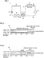
- Fig. 1 generally shows a configuration of a refrigeration cycle apparatus according to an embodiment of the present disclosure. It should be noted that Fig. 1 functionally shows how each component in the refrigeration cycle apparatus is connected and arranged, and the figure does not necessarily show arrangement in a physical space.
- a refrigeration cycle apparatus 1 includes a compressor 10, a condenser 20, a heat exchanger 30, an expansion valve 50, an evaporator 60, and pipes 81 to 85.
- Fig. 1 shows a refrigerant circuit of a simple refrigeration cycle apparatus in which refrigerant flows through compressor 10, condenser 20, heat exchanger 30, expansion valve 50, and evaporator 60 in this order and returns to compressor 10.
- the refrigerant is used a carbon dioxide (hereinafter referred to as CO 2 )-containing refrigerant, e.g., a non-azeotropic mixed refrigerant of R463A.
- Compressor 10 suctions refrigerant from pipe 85, compresses the suctioned refrigerant, and discharges the compressed refrigerant to pipe 80.
- Compressor 10 is configured to be adjusted in rotational speed in response to a control signal received from a control device (not shown). Adjusting compressor 10 in rotational speed adjusts an amount of refrigerant circulated, and hence refrigeration cycle apparatus 1 in performance.
- Compressor 10 may be of various types, and, for example, while representatively it may be of a scroll type, it can also be of a rotary type, a reciprocating type, or a screw type.
- Condenser 20 receives refrigerant discharged from compressor 10 to pipe 80, condenses the received refrigerant, and passes the condensed refrigerant to pipe 81.
- Condenser 20 is configured such that high-temperature and high-pressure gas refrigerant discharged from compressor 10 exchanges heat with external air. Through this heat exchange, the refrigerant dissipates heat, and accordingly, the refrigerant is condensed into a liquid phase.
- a fan (not shown) supplies condenser 20 with external air with which the refrigerant exchanges heat. Adjusting the fan in rotational speed can adjust the refrigerant in pressure on the discharging side of compressor 10.
- Liquid refrigerant flowing out of condenser 20 flows to expansion valve 50 through pipe 81, a first passage H1 of heat exchanger 30, and pipe 82.
- Expansion valve 50 decompresses the liquid refrigerant into a two-phase refrigerant.
- Evaporator 60 receives the two-phase refrigerant flowing in from pipe 83 and evaporates it to be a gas refrigerant.
- the gas refrigerant flowing out of evaporator 60 returns to the inlet of compressor 10 via pipe 84, a second passage H2 of the heat exchanger, and pipe 85.
- Expansion valve 50 is controlled such that the refrigerant at the outlet of evaporator 60 to be suctioned into compressor 10 has a degree of superheat of about 5 K.
- Heat exchanger 30 has first passage H1 and second passage H2, and is configured to exchange heat between refrigerant flowing through first passage H1 and refrigerant flowing through second passage H2.
- Fig. 2 is a diagram schematically showing a cross section of a heat transfer tube of evaporator 60 when R410A is used as refrigerant.
- a conventional refrigeration apparatus uses refrigerant of a simple substance, an azeotropic refrigerant (R22, R410A, R404A, etc.), or a non-azeotropic refrigerant (R407C, etc.) which does not contain CO 2 .
- evaporator 60 has a dry-out area in a range of a degree of dryness of 0.9 to 1.0 and hence in a small area. Accordingly, evaporator 60 has an area of 90% or more thereof with a two-phase refrigerant flowing therethrough in an annular flow, and thus presents satisfactory heat transfer performance between the refrigerant and the heat transfer tube.
- Fig. 3 is a diagram schematically showing the cross section of the heat transfer tube of evaporator 60 when R463A is used as refrigerant.
- R463A is a non-azeotropic mixed refrigerant containing CO 2 , and has a boiling point lower than that of R410A and thus easily evaporates.
- evaporator 60 has a dry-out state from a portion having a degree of dryness of about 0.8.
- the former enters a dry-out state from a portion having a degree of dryness lower by about 10% than the latter.
- evaporator 60 has an increased dry-out area resulting in reduced heat transfer performance.
- expansion valve 50 when expansion valve 50 is controlled such that the refrigerant at the outlet of evaporator 60 to be suctioned into compressor 10 has a degree of superheat of about 5 K, evaporator 60 has a significantly decreased evaporation temperature, resulting in poor energy-saving performance.
- evaporator 60 by inhibiting evaporation of CO 2 or helping to form a liquid film of a two-phase refrigerant on the wall surface of the heat transfer tube, or the like, evaporator 60 is prevented from having the heat transfer tube in a dry-out state.
- miscible oil soluble in refrigerant is used as refrigerator oil.
- miscible oil which is non-volatile oil
- the refrigerant has a raised boiling point, and even when the refrigerant receives heat, the refrigerant is resistant to evaporation, which suppresses a dry-out state of the heat transfer tube.
- no oil separator be provided at a discharging piped portion of compressor 10, as shown in Fig. 1 .
- heat exchanger 30 heats the refrigerant flowing out of evaporator 60 so that a sufficient degree of superheat is obtained at the inlet of compressor 10.
- heat exchanger 30 refrigerant flowing out of evaporator 60 and passing through second passage H2 is heated with a liquid refrigerant of high temperature passing through first passage H1.
- Enclosing the miscible oil in a larger amount is better for preventing evaporator 60 from having a portion in the dry-out state.
- the miscible oil is enclosed in an amount equal to or larger than that of oil held by a typical compressor, it increases an oil circulation rate in the refrigerant circuit, and the liquid refrigerant in evaporator 60 is more resistant to evaporation.
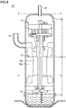
- Fig. 4 is a diagram for illustrating an amount of miscible oil enclosed in the refrigeration cycle apparatus according to the present embodiment.
- compressor 10 has an outer shell composed of a sealed container 11.
- Sealed container 11 includes, for example, an upper case 11a, a barrel portion 11b, and a lower case 11c.
- Upper case 11a is a member constituting an upper portion of sealed container 11.
- Barrel portion 11b is a member constituting a central portion of sealed container 11.
- Lower case 11c is a member constituting a lower portion of sealed container 11.
- Upper case 11a is, for example, a hemispherical member, and constitutes a part of sealed container 11 constituting the outer shell of compressor 10 of a sealed type.
- a discharging pipe 16 for discharging the refrigerant is provided at a top of upper case 11a which is a center in plan view, and is connected to pipe 80 shown in Fig. 1 .
- Sealed container 11 houses an oil pump 14, a motor 13, and a scroll type compression unit 12 as contents.
- Scroll type compression unit 12, motor 13, and oil pump 14 are disposed successively in this order from the top to the bottom of sealed container 11.
- a suction pipe 15 for suctioning the refrigerant is attached to a portion of barrel portion 11b between scroll type compression unit 12 and motor 13.
- Suction pipe 15 is connected to pipe 85 shown in Fig. 1 .
- Motor 13 includes a rotor 13a and a stator 13b.
- refrigerator oil is enclosed in an amount that does not immerse rotor 13a in order to reduce resistance against rotation for motor 13.
- refrigeration cycle apparatus 1 encloses miscible oil in an amount equal to or larger than a level corresponding to a lower surface of rotor 13a as indicated in Fig. 4 by X-X. More preferably, refrigeration cycle apparatus 1 encloses miscible oil in an amount equal to or larger than a level corresponding to an upper surface of sealed container 11 as indicated in Fig. 4 by Y-Y. When the miscible oil is enclosed in the amount equal to or larger than the level corresponding to the upper surface of sealed container 11 as indicated in Fig.
- the miscible oil fills sealed container 11, the enclosed miscible oil spills out of sealed container 11. Since the miscible oil dissolves in the refrigerant, the miscible oil is discharged from compressor 10 together with the refrigerant, and circulates through the refrigerant circuit while refrigeration cycle apparatus 1 is in operation.
- compressor 10 While in general it is preferable that compressor 10 avoid liquid compression, the miscible oil, which is liquid, may fill sealed container 11 insofar as the miscible oil does so for a short period of time before the miscible oil is delivered out, such as when starting the apparatus or the like.
- compressor 10 it is preferable to operate compressor 10 at a lower rotational speed than in normal operation in order to avoid damage to compressor 10 due to liquid compression for a prescribed period of time (of about 3 minutes) immediately after it is actuated.
- levels X-X and Y-Y are a guide indicating an amount of miscible oil enclosed in a refrigeration cycle, and it is not a requirement that compressor 10 reserves miscible oil in an amount equal to or larger than level X-X or Y-Y when the apparatus is started, and the enclosed miscible oil may be dispersed in condenser 20, evaporator 60, and the like.
- compressor 10 reserves miscible oil therein in an amount such that rotor 13a is not immersed in the miscible oil.
- refrigeration cycle apparatus 1 encloses miscible oil in an amount equal to or more than an amount by which at least a portion of rotor 13a of motor 13 is immersed in the miscible oil inside sealed container 11 serving as a casing of compressor 10.
- the enclosed amount of the miscible oil is larger than a spatial volume of compressor 10.
- the spatial volume of compressor 10 is an internal volume of sealed container 11 serving as the casing of compressor 10 minus a volume of its contents, i.e., motor 13, scroll type compression unit 12, oil pump 14 and the like.
- evaporator 60 includes a smooth tube and a fluted tube.
- evaporator 60 has a heat transfer tube that is a smooth tube, it has a small effect in agitating refrigerant, which reduces an amount of heat received by the CO 2 in the mixed refrigerant and can delay evaporation.
- a heat transfer tube of evaporator 60 in a range of a high degree of dryness of 0.8 or more is an internally fluted tube, surface tension helps to form liquid film on the internal wall of the tube, and the tube is thus resistant to a dry-out state.
- Fig. 5 is a diagram schematically showing the cross section of the heat transfer tube of evaporator 60 when R463A is used as refrigerant in the present embodiment.
- evaporator 60 includes a smooth tube 60a and a fluted tube 60b.
- Fig. 6 is a cross section of smooth tube 60a.
- evaporator 60 includes smooth tube 60a.
- Smooth tube 60a has an unfluted internal wall surface.
- smooth tube 60a is used as a heat transfer tube to reduce an area of a dry-out state.
- Fig. 7 shows a cross section of fluted tube 60b.
- Fig. 8 is a partial enlarged view of the cross section of fluted tube 60b.
- evaporator 60 further includes fluted tube 60b in addition to smooth tube 60a.
- Fluted tube 60b has an internal wall surface fluted 62.
- Fluted tube 60b is provided downstream of smooth tube 60a.
- smooth tube 60a For an area having a degree of dryness of 0.8 or more, a flute allowing surface tension to be caused to help to form liquid film is more advantageous in suppression of a dry-out state than the flute's agitation effect resulting in evaporation. Therefore, as shown in Fig. 5 , it is preferable to arrange smooth tube 60a in an upstream portion having a thick liquid film, and fluted tube 60b in a downstream portion having a reduced liquid film.
- evaporator 60 in order to improve heat transfer performance in evaporator 60, it is preferable in the present embodiment to pass refrigerant through evaporator 60 at a flow velocity falling within some range to help to form a liquid film in the heat transfer tube.
- the refrigerant has a flow velocity set in some range to attain an annular flow even in the portion of the area of a high degree of dryness of 0.8 or more
- evaporator 60 can have a heat transfer tube having an internal wall with liquid film formed thereon.
- FIG. 9 is a Baker chart representing a relationship between degree of dryness and flow velocity.
- the Baker chart shown in Fig. 9 is a characteristic diagram representing a flow regime of refrigerant in a gas-liquid two-phase state.
- the vertical axis and the horizontal axis each represent a value representing a flowing state of refrigerant, and the vertical axis is Gg/ ⁇ and the horizontal axis is ⁇ ⁇ ⁇ ⁇ Gl/Gg.
- the vertical axis corresponds to a magnitude of a mass velocity of a gas phase of refrigerant.
- the refrigerant has a gas phase with larger mass velocities for upper sides.
- the horizontal axis corresponds to a ratio in mass velocity of the gas phase and the liquid phase of the refrigerant, that is, a degree of dryness.
- the degree of dryness decreases toward the right side.
- ⁇ and ⁇ are parameters represented in the following expressions (1) and (2), respectively. Symbols in the expressions and figure are G: refrigerant's mass velocity [kg/(m 2 • h)], ⁇ : density, ⁇ : viscosity, and ⁇ : surface tension. Each symbol's subscripts are g: refrigerant's gas phase, 1: refrigerant's liquid phase, w: water, and a: air.
- ⁇ ⁇ g/ ⁇ a ⁇ ⁇ 1 / ⁇ w 1 / 2
- ⁇ ⁇ 1 / ⁇ w 1 / 4 ⁇ ⁇ 1/ ⁇ w ⁇ ⁇ 1 / ⁇ w 2 1 / 3
- 1 refrigeration cycle apparatus 11a upper case, 10 compressor, 11 sealed container, 11b barrel portion, 11c lower case, 12 scroll type compression unit, 13 motor, 13a stator, 13b rotor, 14 oil pump, 15 suction pipe, 16 discharging pipe, 20 condenser, 30 heat exchanger, 50 expansion valve, 60 evaporator, 60a smooth tube, 60b fluted tube, 80, 81, 82, 83, 84 and 85 pipe, HI first passage, H2 second passage.
Landscapes
- Engineering & Computer Science (AREA)
- Mechanical Engineering (AREA)
- General Engineering & Computer Science (AREA)
- Physics & Mathematics (AREA)
- Thermal Sciences (AREA)
- Chemical & Material Sciences (AREA)
- Chemical Kinetics & Catalysis (AREA)
- Applications Or Details Of Rotary Compressors (AREA)
Abstract
Description
- The present invention relates to a refrigeration cycle apparatus and a refrigerator.
-
WO 2002/095302 discloses a refrigeration cycle apparatus using carbon dioxide as a main refrigerant. - PTL 1:
WO 2002/095302 - In recent years, a natural refrigerant such as carbon dioxide has attracted attention as refrigerant. When refrigerant which does not contain carbon dioxide is used in an appropriate amount, the refrigerant flows through a flow path pipe of an evaporator in a flow regime referred to as an annular flow which forms a liquid film on an internal wall surface of a heat transfer tube. In contrast, a non-azeotropic mixed refrigerant containing carbon dioxide (R463A, etc.) has a low boiling point and tends to evaporate. Accordingly, when a refrigeration cycle apparatus uses the non-azeotropic mixture refrigerant containing carbon dioxide, with an evaporator having liquid refrigerant in a small amount at a low flow velocity, a heat transfer tube has liquid film disappearing at a low degree of dryness of about 0.8 in an evaporation process. Hereinafter, such a state with liquid film disappearing will be referred to as a dry-out state.
- In the dry-out state, no liquid film is formed on the internal wall surface of the heat transfer tube, and a two-phase refrigerant flows through the heat transfer tube in a mist flow with droplets mixed therein. When heat transfer performance when heat is transferred from a gas refrigerant to a pipe is compared with heat transfer performance when heat is transferred from a liquid refrigerant to the pipe, the former deteriorates to 1/100 to 1/1000 of the latter. Therefore, when the evaporator has an increased dry-out area, the evaporator has a significantly reduced heat transfer performance.
- When the evaporator has a reduced heat transfer performance, refrigerant would be sent to the compressor in a mist flow with a low degree of dryness, and there is a possibility of failing to ensure a degree of superheat (SH) for the refrigerant at the inlet of the compressor. Accordingly, liquid compression may occur in the compressor.
- The present invention has been made in order to solve such a problem as described above, and an object of the present invention is to provide a refrigeration cycle apparatus and refrigerator configured to use a carbon dioxide-containing refrigerant and facilitate ensuring a degree of superheat for refrigerant at an inlet of a compressor.
- The presently disclosed refrigeration cycle apparatus comprises: a refrigerant circuit in which a carbon dioxide-containing refrigerant circulates to flow through a compressor, a condenser, an expansion valve and an evaporator, and return to the compressor. A miscible oil is enclosed in the refrigerant circuit as a refrigeration oil, the miscible oil having miscibility with the refrigerant. The compressor has a motor inside a casing of the compressor. An enclosed amount of the miscible oil is equal to or more than an amount by which at least a portion of a rotor of the motor is immersed in the miscible oil inside the casing of the compressor.
- When the presently disclosed refrigeration cycle apparatus and refrigerator use a carbon dioxide-containing refrigerant, with an evaporator having a liquid refrigerant therein in an amount which is small to some extent, it still prevents the refrigerant from evaporating, as the liquid refrigerant contains miscible oil at a high ratio.
- Accordingly, a dry-out state is less likely to occur, and a degree of superheat is ensured at the inlet of the compressor.
-
-
Fig. 1 shows a general configuration of a refrigeration cycle apparatus according to an embodiment of the present disclosure. -
Fig. 2 is a diagram schematically showing a cross section of a heat transfer tube of an evaporator when R410A is used as refrigerant. -
Fig. 3 is a diagram schematically showing the cross section of the heat transfer tube of the evaporator when R463A is used as refrigerant. -
Fig. 4 is a diagram for illustrating an amount of miscible oil enclosed in the refrigeration cycle apparatus according to the present embodiment. -
Fig. 5 is a diagram schematically showing the cross section of the heat transfer tube of the evaporator when R463A is used as refrigerant in the present embodiment. -
Fig. 6 is a diagram showing a cross section of asmooth tube 60a. -
Fig. 7 is a diagram showing a cross section of afluted tube 60b. -
Fig. 8 is a partial enlarged view of the cross section offluted tube 60b. -
Fig. 9 is a Baker chart showing a relationship between degree of dryness and flow velocity. - Hereinafter, embodiments of the present invention will be described in detail with reference to the drawings. Hereinafter, while a plurality of embodiments will be described, the configurations described in the embodiments are intended to be combined together, as appropriate, in the present application as originally filed. In the figures, identical or corresponding components are identically denoted and will not be described redundantly.
-
Fig. 1 generally shows a configuration of a refrigeration cycle apparatus according to an embodiment of the present disclosure. It should be noted thatFig. 1 functionally shows how each component in the refrigeration cycle apparatus is connected and arranged, and the figure does not necessarily show arrangement in a physical space. - Referring to
Fig. 1 , arefrigeration cycle apparatus 1 includes acompressor 10, acondenser 20, aheat exchanger 30, anexpansion valve 50, anevaporator 60, andpipes 81 to 85. For simplicity of illustration,Fig. 1 shows a refrigerant circuit of a simple refrigeration cycle apparatus in which refrigerant flows throughcompressor 10,condenser 20,heat exchanger 30,expansion valve 50, andevaporator 60 in this order and returns tocompressor 10. As the refrigerant is used a carbon dioxide (hereinafter referred to as CO2)-containing refrigerant, e.g., a non-azeotropic mixed refrigerant of R463A. -
Compressor 10 suctions refrigerant frompipe 85, compresses the suctioned refrigerant, and discharges the compressed refrigerant topipe 80.Compressor 10 is configured to be adjusted in rotational speed in response to a control signal received from a control device (not shown). Adjustingcompressor 10 in rotational speed adjusts an amount of refrigerant circulated, and hencerefrigeration cycle apparatus 1 in performance.Compressor 10 may be of various types, and, for example, while representatively it may be of a scroll type, it can also be of a rotary type, a reciprocating type, or a screw type. -
Condenser 20 receives refrigerant discharged fromcompressor 10 topipe 80, condenses the received refrigerant, and passes the condensed refrigerant topipe 81.Condenser 20 is configured such that high-temperature and high-pressure gas refrigerant discharged fromcompressor 10 exchanges heat with external air. Through this heat exchange, the refrigerant dissipates heat, and accordingly, the refrigerant is condensed into a liquid phase. A fan (not shown) suppliescondenser 20 with external air with which the refrigerant exchanges heat. Adjusting the fan in rotational speed can adjust the refrigerant in pressure on the discharging side ofcompressor 10. - Liquid refrigerant flowing out of
condenser 20 flows toexpansion valve 50 throughpipe 81, a first passage H1 ofheat exchanger 30, andpipe 82.Expansion valve 50 decompresses the liquid refrigerant into a two-phase refrigerant.Evaporator 60 receives the two-phase refrigerant flowing in frompipe 83 and evaporates it to be a gas refrigerant. The gas refrigerant flowing out ofevaporator 60 returns to the inlet ofcompressor 10 viapipe 84, a second passage H2 of the heat exchanger, andpipe 85.Expansion valve 50 is controlled such that the refrigerant at the outlet ofevaporator 60 to be suctioned intocompressor 10 has a degree of superheat of about 5 K. -
Heat exchanger 30 has first passage H1 and second passage H2, and is configured to exchange heat between refrigerant flowing through first passage H1 and refrigerant flowing through second passage H2. -
Fig. 2 is a diagram schematically showing a cross section of a heat transfer tube ofevaporator 60 when R410A is used as refrigerant. A conventional refrigeration apparatus uses refrigerant of a simple substance, an azeotropic refrigerant (R22, R410A, R404A, etc.), or a non-azeotropic refrigerant (R407C, etc.) which does not contain CO2. As shown inFig. 2 , when R410A is used,evaporator 60 has a dry-out area in a range of a degree of dryness of 0.9 to 1.0 and hence in a small area. Accordingly,evaporator 60 has an area of 90% or more thereof with a two-phase refrigerant flowing therethrough in an annular flow, and thus presents satisfactory heat transfer performance between the refrigerant and the heat transfer tube. -
Fig. 3 is a diagram schematically showing the cross section of the heat transfer tube ofevaporator 60 when R463A is used as refrigerant. R463A is a non-azeotropic mixed refrigerant containing CO2, and has a boiling point lower than that of R410A and thus easily evaporates. When R463A is used,evaporator 60 has a dry-out state from a portion having a degree of dryness of about 0.8. Thus, when R463A is compared with R410A, the former enters a dry-out state from a portion having a degree of dryness lower by about 10% than the latter. Thus,evaporator 60 has an increased dry-out area resulting in reduced heat transfer performance. Further, whenexpansion valve 50 is controlled such that the refrigerant at the outlet ofevaporator 60 to be suctioned intocompressor 10 has a degree of superheat of about 5 K,evaporator 60 has a significantly decreased evaporation temperature, resulting in poor energy-saving performance. - Accordingly, in the present embodiment, by inhibiting evaporation of CO2 or helping to form a liquid film of a two-phase refrigerant on the wall surface of the heat transfer tube, or the like,
evaporator 60 is prevented from having the heat transfer tube in a dry-out state. To do so, miscible oil soluble in refrigerant is used as refrigerator oil. When miscible oil, which is non-volatile oil, is dissolved in refrigerant, the refrigerant has a raised boiling point, and even when the refrigerant receives heat, the refrigerant is resistant to evaporation, which suppresses a dry-out state of the heat transfer tube. In order to circulate the miscible oil through the refrigerant circuit, it is preferable that no oil separator be provided at a discharging piped portion ofcompressor 10, as shown inFig. 1 . - Even when the heat transfer tube has a dry-out state and
evaporator 60 has reduced heat transfer performance,heat exchanger 30 heats the refrigerant flowing out ofevaporator 60 so that a sufficient degree of superheat is obtained at the inlet ofcompressor 10. When the heat transfer tube has a dry-out state andevaporator 60 has reduced heat transfer performance, and a degree of superheat cannot be ensured for refrigerant, then, byheat exchanger 30, refrigerant flowing out ofevaporator 60 and passing through second passage H2 is heated with a liquid refrigerant of high temperature passing through first passage H1. Thus, even whenevaporator 60 has an area dried out and thus having reduced heat transfer performance, the refrigerant can subsequently be heated, and a degree of superheat can be ensured at the inlet ofcompressor 10. - Enclosing the miscible oil in a larger amount is better for preventing
evaporator 60 from having a portion in the dry-out state. When the miscible oil is enclosed in an amount equal to or larger than that of oil held by a typical compressor, it increases an oil circulation rate in the refrigerant circuit, and the liquid refrigerant inevaporator 60 is more resistant to evaporation. -
Fig. 4 is a diagram for illustrating an amount of miscible oil enclosed in the refrigeration cycle apparatus according to the present embodiment. As shown inFig. 4 ,compressor 10 has an outer shell composed of a sealedcontainer 11.Sealed container 11 includes, for example, anupper case 11a, abarrel portion 11b, and alower case 11c.Upper case 11a is a member constituting an upper portion of sealedcontainer 11.Barrel portion 11b is a member constituting a central portion of sealedcontainer 11.Lower case 11c is a member constituting a lower portion of sealedcontainer 11. -
Upper case 11a is, for example, a hemispherical member, and constitutes a part of sealedcontainer 11 constituting the outer shell ofcompressor 10 of a sealed type. - A discharging
pipe 16 for discharging the refrigerant is provided at a top ofupper case 11a which is a center in plan view, and is connected topipe 80 shown inFig. 1 . -
Sealed container 11 houses anoil pump 14, amotor 13, and a scrolltype compression unit 12 as contents. Scrolltype compression unit 12,motor 13, andoil pump 14 are disposed successively in this order from the top to the bottom of sealedcontainer 11. Asuction pipe 15 for suctioning the refrigerant is attached to a portion ofbarrel portion 11b between scrolltype compression unit 12 andmotor 13.Suction pipe 15 is connected topipe 85 shown inFig. 1 . -
Motor 13 includes arotor 13a and astator 13b. In general, refrigerator oil is enclosed in an amount that does not immerserotor 13a in order to reduce resistance against rotation formotor 13. In the present embodiment, however,refrigeration cycle apparatus 1 encloses miscible oil in an amount equal to or larger than a level corresponding to a lower surface ofrotor 13a as indicated inFig. 4 by X-X. More preferably,refrigeration cycle apparatus 1 encloses miscible oil in an amount equal to or larger than a level corresponding to an upper surface of sealedcontainer 11 as indicated inFig. 4 by Y-Y. When the miscible oil is enclosed in the amount equal to or larger than the level corresponding to the upper surface of sealedcontainer 11 as indicated inFig. 4 by Y-Y, and the enclosed miscible oil fills sealedcontainer 11, the enclosed miscible oil spills out of sealedcontainer 11. Since the miscible oil dissolves in the refrigerant, the miscible oil is discharged fromcompressor 10 together with the refrigerant, and circulates through the refrigerant circuit whilerefrigeration cycle apparatus 1 is in operation. - While in general it is preferable that
compressor 10 avoid liquid compression, the miscible oil, which is liquid, may fill sealedcontainer 11 insofar as the miscible oil does so for a short period of time before the miscible oil is delivered out, such as when starting the apparatus or the like. For example, it is preferable to operatecompressor 10 at a lower rotational speed than in normal operation in order to avoid damage tocompressor 10 due to liquid compression for a prescribed period of time (of about 3 minutes) immediately after it is actuated. Note that levels X-X and Y-Y are a guide indicating an amount of miscible oil enclosed in a refrigeration cycle, and it is not a requirement thatcompressor 10 reserves miscible oil in an amount equal to or larger than level X-X or Y-Y when the apparatus is started, and the enclosed miscible oil may be dispersed incondenser 20,evaporator 60, and the like. - While
refrigeration cycle apparatus 1 is in operation, in order to reduce resistance against rotation, it is preferable thatcompressor 10 reserves miscible oil therein in an amount such thatrotor 13a is not immersed in the miscible oil. - As has been discussed above, in the present embodiment,
refrigeration cycle apparatus 1 encloses miscible oil in an amount equal to or more than an amount by which at least a portion ofrotor 13a ofmotor 13 is immersed in the miscible oil inside sealedcontainer 11 serving as a casing ofcompressor 10. - Preferably, the enclosed amount of the miscible oil is larger than a spatial volume of
compressor 10. Note that the spatial volume ofcompressor 10 is an internal volume of sealedcontainer 11 serving as the casing ofcompressor 10 minus a volume of its contents, i.e.,motor 13, scrolltype compression unit 12,oil pump 14 and the like. - More preferably, in
refrigeration cycle apparatus 1 of the present embodiment,evaporator 60 includes a smooth tube and a fluted tube. When evaporator 60 has a heat transfer tube that is a smooth tube, it has a small effect in agitating refrigerant, which reduces an amount of heat received by the CO2 in the mixed refrigerant and can delay evaporation. In contrast, when a heat transfer tube ofevaporator 60 in a range of a high degree of dryness of 0.8 or more is an internally fluted tube, surface tension helps to form liquid film on the internal wall of the tube, and the tube is thus resistant to a dry-out state. -
Fig. 5 is a diagram schematically showing the cross section of the heat transfer tube ofevaporator 60 when R463A is used as refrigerant in the present embodiment. Referring toFig. 5 ,evaporator 60 includes asmooth tube 60a and afluted tube 60b. -
Fig. 6 is a cross section ofsmooth tube 60a. Inrefrigeration cycle apparatus 1 of the present embodiment,evaporator 60 includessmooth tube 60a.Smooth tube 60a has an unfluted internal wall surface. In an area of a low degree of dryness of less than 0.8 which is not in a dry-out state, a smooth tube having no agitation effect therein delays evaporation of CO2 more than a fluted tube does. Therefore, in an upstream area ofevaporator 60,smooth tube 60a is used as a heat transfer tube to reduce an area of a dry-out state. -
Fig. 7 shows a cross section offluted tube 60b.Fig. 8 is a partial enlarged view of the cross section offluted tube 60b. Preferably,evaporator 60 further includesfluted tube 60b in addition tosmooth tube 60a.Fluted tube 60b has an internal wall surface fluted 62.Fluted tube 60b is provided downstream ofsmooth tube 60a. For an area having a degree of dryness of 0.8 or more, a flute allowing surface tension to be caused to help to form liquid film is more advantageous in suppression of a dry-out state than the flute's agitation effect resulting in evaporation. Therefore, as shown inFig. 5 , it is preferable to arrangesmooth tube 60a in an upstream portion having a thick liquid film, andfluted tube 60b in a downstream portion having a reduced liquid film. - Further, in order to improve heat transfer performance in
evaporator 60, it is preferable in the present embodiment to pass refrigerant throughevaporator 60 at a flow velocity falling within some range to help to form a liquid film in the heat transfer tube. When the refrigerant has a flow velocity set in some range to attain an annular flow even in the portion of the area of a high degree of dryness of 0.8 or more,evaporator 60 can have a heat transfer tube having an internal wall with liquid film formed thereon. - A two-phase flow regime for degree of dryness and flow velocity is represented in Baker chart.
Fig. 9 is a Baker chart representing a relationship between degree of dryness and flow velocity. The Baker chart shown inFig. 9 is a characteristic diagram representing a flow regime of refrigerant in a gas-liquid two-phase state. The vertical axis and the horizontal axis each represent a value representing a flowing state of refrigerant, and the vertical axis is Gg/λ and the horizontal axis is λ × ϕ × Gl/Gg. The vertical axis corresponds to a magnitude of a mass velocity of a gas phase of refrigerant. In the figure, the refrigerant has a gas phase with larger mass velocities for upper sides. The horizontal axis corresponds to a ratio in mass velocity of the gas phase and the liquid phase of the refrigerant, that is, a degree of dryness. In the figure, the degree of dryness decreases toward the right side. - Note that λ and ϕ are parameters represented in the following expressions (1) and (2), respectively. Symbols in the expressions and figure are G: refrigerant's mass velocity [kg/(m2 • h)], ρ: density, µ: viscosity, and σ: surface tension. Each symbol's subscripts are g: refrigerant's gas phase, 1: refrigerant's liquid phase, w: water, and a: air.


- Controlling a flow rate to fall within an annular flow range in a vicinity of Gg/λ of 1.E + 0.5 and λ × ϕ ×Gl/Gg of 1.0E + 01, as indicated in
Fig. 9 by a hatched area, helps to form liquid film inevaporator 60 and hence further improvesevaporator 60 in heat transfer performance. - It should be understood that the embodiments disclosed herein have been described for the purpose of illustration only and in a non-restrictive manner in any respect. The scope of the present invention is defined by the terms of the claims, rather than the embodiments description above, and is intended to include any modifications within the meaning and scope equivalent to the terms of the claims.
- 1 refrigeration cycle apparatus, 11a upper case, 10 compressor, 11 sealed container, 11b barrel portion, 11c lower case, 12 scroll type compression unit, 13 motor, 13a stator, 13b rotor, 14 oil pump, 15 suction pipe, 16 discharging pipe, 20 condenser, 30 heat exchanger, 50 expansion valve, 60 evaporator, 60a smooth tube, 60b fluted tube, 80, 81, 82, 83, 84 and 85 pipe, HI first passage, H2 second passage.
Claims (7)
- A refrigeration cycle apparatus comprising:a refrigerant circuit in which a carbon dioxide-containing refrigerant circulates to flow through a compressor, a condenser, an expansion valve, and an evaporator and return to the compressor,a miscible oil being enclosed in the refrigerant circuit as a refrigeration oil, the miscible oil having miscibility with the refrigerant,the compressor having a motor inside a casing of the compressor,an enclosed amount of the miscible oil being equal to or more than an amount by which at least a portion of a rotor of the motor is immersed in the miscible oil inside the casing of the compressor.
- The refrigeration cycle apparatus according to claim 1, wherein the enclosed amount of the miscible oil is larger than a spatial volume of the compressor.
- The refrigeration cycle apparatus according to claim 1 or 2, wherein the evaporator includes a smooth tube having an unfluted internal wall surface.
- The refrigeration cycle apparatus according to claim 3, wherein the evaporator incudes downstream of the smooth tube a fluted tube having a fluted internal wall surface.
- The refrigeration cycle apparatus according to claim 1, wherein a flow velocity of the refrigerant in the evaporator is a flow velocity allowing an annular flow to be maintained.
- The refrigeration cycle apparatus according to claim 1, further comprising a heat exchanger configured to exchange heat between the refrigerant flowing out of the condenser and the refrigerant flowing out of the evaporator.
- A refrigerator comprising the refrigeration cycle apparatus according to any one of claims 1 to 6.
Applications Claiming Priority (1)
| Application Number | Priority Date | Filing Date | Title |
|---|---|---|---|
| PCT/JP2019/021835 WO2020240858A1 (en) | 2019-05-31 | 2019-05-31 | Refrigeration cycle device and refrigerator |
Publications (2)
| Publication Number | Publication Date |
|---|---|
| EP3978829A1 true EP3978829A1 (en) | 2022-04-06 |
| EP3978829A4 EP3978829A4 (en) | 2022-06-08 |
Family
ID=73554014
Family Applications (1)
| Application Number | Title | Priority Date | Filing Date |
|---|---|---|---|
| EP19931481.6A Withdrawn EP3978829A4 (en) | 2019-05-31 | 2019-05-31 | REFRIGERATION CIRCUIT DEVICE AND REFRIGERATOR |
Country Status (4)
| Country | Link |
|---|---|
| EP (1) | EP3978829A4 (en) |
| JP (1) | JPWO2020240858A1 (en) |
| CN (1) | CN113853502A (en) |
| WO (1) | WO2020240858A1 (en) |
Families Citing this family (1)
| Publication number | Priority date | Publication date | Assignee | Title |
|---|---|---|---|---|
| WO2023243022A1 (en) * | 2022-06-16 | 2023-12-21 | 三菱電機株式会社 | Heat pump device |
Family Cites Families (13)
| Publication number | Priority date | Publication date | Assignee | Title |
|---|---|---|---|---|
| JPS5943206B2 (en) * | 1981-07-16 | 1984-10-20 | 株式会社 栗田機械製作所 | Filter press stock solution supply plate |
| US4895496A (en) * | 1988-06-08 | 1990-01-23 | Copeland Corporation | Refrigeration compressor |
| JPH02143094A (en) * | 1988-11-25 | 1990-06-01 | Kobe Steel Ltd | Heat exchanger equipped with heat transfer tube |
| JPWO2002095302A1 (en) * | 2001-05-23 | 2004-09-09 | 松下電器産業株式会社 | Refrigeration cycle device |
| JP2007178029A (en) * | 2005-12-27 | 2007-07-12 | Mitsubishi Electric Corp | Refrigeration air conditioner |
| JP2007315639A (en) * | 2006-05-24 | 2007-12-06 | Matsushita Electric Ind Co Ltd | Evaporator and refrigeration cycle apparatus using the same |
| JP2008020166A (en) * | 2006-07-14 | 2008-01-31 | Kobelco & Materials Copper Tube Inc | Inner surface grooved heat-transfer tube for evaporator |
| JP6061665B2 (en) * | 2012-12-19 | 2017-01-18 | 三菱電機株式会社 | Oil return structure of air conditioner and air conditioner |
| JP5943206B2 (en) * | 2013-05-16 | 2016-06-29 | 日立アプライアンス株式会社 | CO2 heat pump water heater |
| JP5951676B2 (en) * | 2014-04-30 | 2016-07-13 | 三菱重工冷熱株式会社 | Control method of refrigeration equipment |
| CN107076466B (en) * | 2014-10-16 | 2020-02-07 | 三菱电机株式会社 | Refrigeration cycle device |
| US11193482B2 (en) * | 2014-12-17 | 2021-12-07 | Hitachi Industrial Equipment Systems Co., Ltd. | Air compressing apparatus and control method |
| DE102016204378B4 (en) * | 2016-03-16 | 2025-11-27 | Weiss Umwelttechnik Gmbh | Test chamber |
-
2019
- 2019-05-31 JP JP2021522594A patent/JPWO2020240858A1/ja active Pending
- 2019-05-31 CN CN201980096628.7A patent/CN113853502A/en active Pending
- 2019-05-31 WO PCT/JP2019/021835 patent/WO2020240858A1/en not_active Ceased
- 2019-05-31 EP EP19931481.6A patent/EP3978829A4/en not_active Withdrawn
Also Published As
| Publication number | Publication date |
|---|---|
| EP3978829A4 (en) | 2022-06-08 |
| WO2020240858A1 (en) | 2020-12-03 |
| JPWO2020240858A1 (en) | 2020-12-03 |
| CN113853502A (en) | 2021-12-28 |
Similar Documents
| Publication | Publication Date | Title |
|---|---|---|
| CN101427083B (en) | freezer | |
| EP3051225B1 (en) | Refrigeration cycle device | |
| US10247459B2 (en) | Refrigeration cycle apparatus | |
| US10415855B2 (en) | Refrigeration cycle apparatus | |
| EP2565557B1 (en) | Refrigeration cycle device and refrigerant circulation method | |
| CN101427084B (en) | Refrigerating device | |
| EP2009371B1 (en) | Heat pump hot water supplier | |
| CN102844631A (en) | Air conditioning apparatus | |
| JP6722690B2 (en) | Refrigerator | |
| CN106104170A (en) | Refrigeration cycle device | |
| CN102679604A (en) | Cooling cycle apparatus | |
| CN110785617A (en) | Air conditioner | |
| EP3978829A1 (en) | Refrigeration cycle device and refrigerator | |
| JP2007285680A (en) | Refrigeration equipment | |
| JP2007315227A (en) | Expander-integrated compressor and refrigeration cycle apparatus | |
| EP3438565B1 (en) | Refrigeration device | |
| WO2022030102A1 (en) | Hot water supply system | |
| JP6395643B2 (en) | Air conditioner | |
| EP3434999B1 (en) | Refrigeration cycle apparatus | |
| JP2004353904A (en) | Accumulator and air conditioner | |
| JP3356601B2 (en) | Heat pump device using non-azeotropic refrigerant | |
| JP7839438B2 (en) | Refrigeration cycle equipment | |
| JP2004232986A (en) | Refrigerator | |
| EP3404341A1 (en) | Refrigeration cycle apparatus and liquid circulating apparatus including the same | |
| WO2020008916A1 (en) | Refrigeration cycle device and method for controlling same |
Legal Events
| Date | Code | Title | Description |
|---|---|---|---|
| STAA | Information on the status of an ep patent application or granted ep patent |
Free format text: STATUS: THE INTERNATIONAL PUBLICATION HAS BEEN MADE |
|
| PUAI | Public reference made under article 153(3) epc to a published international application that has entered the european phase |
Free format text: ORIGINAL CODE: 0009012 |
|
| STAA | Information on the status of an ep patent application or granted ep patent |
Free format text: STATUS: REQUEST FOR EXAMINATION WAS MADE |
|
| 17P | Request for examination filed |
Effective date: 20211124 |
|
| AK | Designated contracting states |
Kind code of ref document: A1 Designated state(s): AL AT BE BG CH CY CZ DE DK EE ES FI FR GB GR HR HU IE IS IT LI LT LU LV MC MK MT NL NO PL PT RO RS SE SI SK SM TR |
|
| A4 | Supplementary search report drawn up and despatched |
Effective date: 20220509 |
|
| RIC1 | Information provided on ipc code assigned before grant |
Ipc: F25B 40/00 20060101ALN20220502BHEP Ipc: F25B 49/02 20060101ALI20220502BHEP Ipc: F25B 9/00 20060101ALI20220502BHEP Ipc: F25B 31/02 20060101ALI20220502BHEP Ipc: F04B 39/02 20060101ALI20220502BHEP Ipc: F25B 1/00 20060101AFI20220502BHEP |
|
| DAV | Request for validation of the european patent (deleted) | ||
| DAX | Request for extension of the european patent (deleted) | ||
| GRAP | Despatch of communication of intention to grant a patent |
Free format text: ORIGINAL CODE: EPIDOSNIGR1 |
|
| STAA | Information on the status of an ep patent application or granted ep patent |
Free format text: STATUS: GRANT OF PATENT IS INTENDED |
|
| RIC1 | Information provided on ipc code assigned before grant |
Ipc: F25B 40/00 20060101ALN20240208BHEP Ipc: F25B 49/02 20060101ALI20240208BHEP Ipc: F25B 9/00 20060101ALI20240208BHEP Ipc: F25B 31/02 20060101ALI20240208BHEP Ipc: F04B 39/02 20060101ALI20240208BHEP Ipc: F25B 1/00 20060101AFI20240208BHEP |
|
| INTG | Intention to grant announced |
Effective date: 20240312 |
|
| STAA | Information on the status of an ep patent application or granted ep patent |
Free format text: STATUS: THE APPLICATION IS DEEMED TO BE WITHDRAWN |
|
| 18D | Application deemed to be withdrawn |
Effective date: 20240713 |